Transcript
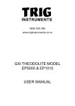
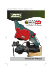
HOW TO
INSTRUMENTS
Test and calibrate a
Robovector Vector 5 laser
WARNING: DO NOT USE THE METHOD
DESCRIBED IN THE USER MANUAL TO
CALIBRATE YOUR ROBOVECTOR, THAT METHOD
RELIES ON ALL YOUR SURFACES BEING
PERFECT AND LEVEL WHICH THEY WILL NOT BE!
WHEN TO TEST
If the Vector 5 gets dropped, knocked or it has been
more than 6 months since the last test, it is wise to
test the laser using the method below, or bring it in to
the Trig Instruments service department for a full factory
test and adjustment.
There are two ways to adjust the Vector 5 Laser. In
our service department we adjust lasers opticaly using
a precision range. This is the most precise method.
However if the user is careful, they can test and
calibrate the laser on site using the method below.
the beam parallel on each side. Remove the key
after each adjustment, then go back to the beginning
of the procedure to test if you have made the
adjustment in the right direction and by the right
amount. If not, repeat by adjusting anticlockwise.
This axis is in adjustment when the gap between your
mark “A” and mark “B” are the same at each end of
the run. Proceed to “Testing Axis Y”
TESTING AXIS Y
• After adjusting the X Axis, set the laser up on a
tripod or a firm stable surface outside a doorway
pointing into a large room. The longer the run the
better, up to about 30m
• Aim one of the the side beams so that it skims the
edge of the door frame and then make a mark in the
centre of the beam on the doorframe and do the same
where the beam hits the wall. This has now set up
two marks that are level with each other (see Fig 2)
TESTING AXIS X
• Set the laser up on a tripod or a firm stable surface
in aproximatly the middle of a run which has a solid
vertical surface at each end like a wall. The longer
the run the better, up to about 30m each way
• Aim the two side beams at the Walls (see Fig 1)
WALL 1
WALL 1
WALL 2
ROBOVECTOR
LASER BEAM
TRIPOD OR BASE
DOOR FRAME
• At “Wall 1” make a mark in the centre of the beam
and label it “A” do the same at “Wall 2”
• Rotate the laser 180 degrees and line the two beams
up beside the marks you have made
• Make a mark at each wall again and label them “B”
• Now measure the difference in height at each end
• If the heights are the same at each wall then this
axis is in good adjustment. If not, proceed to “Axis X
Adjustment”
AXIS X ADJUSTMENT
• On one side of the laser there is a small adjusting
screw cap under one of the side windows. Remove
this cap and insert the hex-key which was provided
with the laser into the small hex-screw inside . Make
an adjustment clockwise to this hex-screw to bring
www.triginstruments.co.nz
FIG 2 - TOP VIEW
• Rotate the laser so that the front beam is now
skimming the door frame and aimed at the mark on
the wall
• Measure the difference in height at each end
• If the heights are the same then this side is in good
adjustment. If not, proceed to “Axis Y Adjustment”
AXIS Y ADJUSTMENT
• On the front of the laser there is a small adjusting
screw cap under the front window. Remove this cap
and insert the hex-key which was provided with the
laser into the small hex-screw inside. Make an
adjustment to the hex screw to bring the beam parallel
to the marks made previously.
0800 500 460
© 2008 Trig Instruments all rights reserved
FIG 1 - SIDE VIEW