1
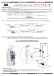
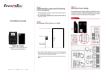
Installer Guide
Adaptability to Enhanced Security
AdapTec Plus combines power supply and door access controller features
in a compact casing for an encrypted and secure I/O function, enhancing door access control functionalities and easing installation processes.
AdapTec Plus is an exceptional FingerTec accessory in a small package!
understanding adaptec plus FUNCTIONS
Enhanced Security with Encrypted Signals
It supports FingerTec encrypted 26-bit Wiegand communication output;
providing enhanced security level for extra protection.
Power Up Terminals & Door Lock Systems
A single AdapTec Plus can support a maximum of 2 units of FingerTec
terminals and 2 sets of door lock accessories such as the EM lock and drop
bolt in one single system installation.
Prolonged Life Span of Hardware
With data encryption, the life span of the terminals can be prolonged
without the risk of short-circuiting when using AdapTec Plus
Control IN/OUT Terminals at an Entrance
AdapTec Plus is a perfect choice for an IN/OUT installation, where a door
is controlled both at the entrance and the exit.
Supports Rechargeable Backup Battery
Connects well to any 12VDC rechargeable backup battery, providing
power to ensure protection of access during any events of power failure.
Emergency Alerts with Siren
Compatible with an NC siren type with a maximum of 0.5A load for an
emergency event e.g. if the terminal is being dismantled without authorization.
Seamless Integration with FingerTec Terminals
Mix and match the FingerTec terminals via AdapTec Plus for a cost effective access control system suitable for small and medium sized offices.
UNDERSTANDING THE TECHNICAL SPECIFICATIONS
PHYSICAL APPEARANCE
Surface finishing
Acrylonitrile Butadiene Styrene (ABS)
Dimension, mm
212 x 49 x 114
Weight, kg
0.6
CPU
High Performance RISC CPU
Power input
AC 110 ~ 240V (Universal Input)
Power output
12VDC 3A
Backup Power system
UPS or 12VDC Rechargeable battery
POWER SUPPLY
INPUT – OUTPUT SIGNAL
Input signal26-bit FingerTec encrypted Weigand signal
Output signal
12VDC 0.5A Siren
12VDC 3A EM output (NO/NC Type door locks)
Over input voltage Yes, 3 long beeps
Door release Yes, 2 short beeps
Door force open Yes, continuous beeps (May opt to output external siren system)
Illegal dismantle FingerTec terminals
Yes, continuous beeps (May opt to output external siren
system)
Door unlock timer
VR type, LED blinks to indicate unlock time in Seconds.
On Board LED indicators
EM LED lit up – door lock output is working.
Status LED lit up – CPU is working.
Battery low LED lit up – Battery is low and cut-off.
Over voltage alarm
>15 VDC
Fuses
PTC type
Battery cut-off
8.5 ~ 9.5 VDC
ALERTS & NOTIFICATIONS
ON BOARD PROTECTION
NOTE: Specifications are subject to change. Check http://product.fingertec.com for latest product
information.
understanding THE DESIGN
AdapTec Plus consists of 2 main modules
3
4
1
2
1 Power supply/power input module
2 Power output/access control module
1
2
3 Door lock timer
4 LED status indicator
3 4
5
6
Power supply/power input module
1 This portion is to be connected to a power source with AC110~240V. An AC
current should be supplied into this side and a 12VDC 3A current will be generated as output.
2 These two cables, -V and +V are default and are connected to the inner part
of AdapTec. Please do not remove or change these cables.
Power output/access control module
3 These cables connect to the 12VDC power from the power supply/input
module. Do not remove or dismantle these cables.
4 These cables connect to a 12VDC rechargeable backup battery. During a
power failure, the backup battery will power up AdapTec Plus.
5 These are the power output ports from AdapTec Plus. Refer to the wiring
diagram for details.
6 These are the Wiegand data input ports from the FingerTec terminals. Refer
to the wiring diagram for details.
Other Features
You will find a buzzer, 4 LED indicators, and a door lock timer on the
board. Check and set each of them accordingly after powering up the
system.
1
2
3
4
1 You will hear the buzzer beep to indicate:
• Unlocked Door (Short buzz)
Door is unlocked and access granted (during verification or pressing push
release button).
• Over Voltage (Non-stop buzzing after startup)
Over voltage of power input (Stop the power supply to the system immediately and check the input voltage, consult [email protected])
2 Adjust the door lock timer for a longer or shorter unlocking time period
by turning the screw clockwise. Count the LED blinks after turning it. Each
blink represents 1 second and the recommended time period is 5 seconds (5
blinks).
3 Select the type of door lock to use, NO type or NC type.
• PIN 1&2 – NO Type door lock system.
• PIN 2&3 – NC Type door lock system (default)
4 The LED lights up to indicate the following:
• EM lock LED - The EM lock system is charged up and working properly.
• Status LED - The overall system is working properly.
Note: Contact [email protected] if either of the above LED lights are not
lit up.
• Bat Low LED - The battery is weak and needs to be charged or replaced.
DETAILS OF WIRING
AdapTec Plus supports 2 types of installations, Convenient or Secure. You
can select between modes by applying different wiring arrangements during
installation. Under Convenient mode, AdapTec Plus will unlock doors immediately after receiving responses from FingerTec devices. This feature is supw
ported by all FingerTec models.
WelcomeCheck-In
01-01 09:00 Sun
1
2
4
5
7
8
9
0
MENU
3
ESC
For installations using Secure mode, there will be a 1s time delay when unlocking the door after verification at FingerTec devices. This delay is due to the
26-bit Wiegand transmission of encrypted password from device to AdapTec
Plus. This is an optional security feature provided by AdapTec Plus for users
who favor more security (slight delay) over convenience (no delays).
OK
R2
Q2i
suppor t@finger tec.com
6
suppor t@finger tec.com
AdapTec Plus works with FingerTec terminals via an encrypted Wiegand
signal to control the door open-close mechanism. Please make sure you are
w
using the following FingerTec models that support the encrypted 26-bit Wiegand signal to work with the AdapTec Plus to setup a door lock system:
WelcomeCheck-In
01-01 09:00 Sun
1
3
5
7
8
9
0
MENU
ESC
6
OK
R2
Q2i
suppor t@finger tec.com
2
4
suppor t@finger tec.com
w
WelcomeCheck-In
01-01 09:00 Sun
1
2
4
5
7
8
9
0
MENU
3
ESC
WelcomeCheck-In
01-01
09:00 Sun
12-01-01 SUN
6
1
R2
Q2i
1
w
WelcomeCheck-In
01-01 09:00 Sun
suppor t@finger tec.com
w
OK
2
3
4
5
7
8
9
0
MENU
2
3
4
5
7
8
9
0
MENU
ESC
6
OK
ESC
6
OK
H2i
suppor t@finger tec.com
suppor t@finger tec.com
suppor t@finger tec.com
Q2i
Q2i
AC900
R2
12-01-01
suppor t@finger tec.com
R2
m-Kadex
R2
Q2i
suppor t@finger tec.com
Kadex
suppor t@finger tec.com
suppor t@finger tec.com
SUN
H2i
suppor t@finger tec.com
suppor t@finger tec.com
H2i
12-01-01
Face ID 2
Face ID 3
i-Kiosk 100 Plus
SUN
Step 1
Look for the power input port on the
FingerTec terminal. Normally the connection ports on the terminals are
marked as PWR/+12V (red wire) and
GND (black wire).
12-01-01
12-01-01
SUN
SUN
H2i
Convenient Installation: See diagram 1, page 8
for details. Secure Installation: See diagram 2,
page 8 for details.
suppor t@finger tec.com
suppor t@finger tec.com
suppor t@finger tec.com
suppor t@finger tec.com
Step 2
Convenient Installation: Look for the
door lock output port NO and GND
from the terminal.
Secure Installation: Look for the Wiegand output port, WDO (green), WD1
(white) and GND (black) from the terminal.
Step 3
Connect the wires from the terminals
to AdapTec Plus.
Step 4
Connect the wires from AdapTec Plus
to the door lock system.
H2i
suppor t@finger tec.com
H2i
suppor t@finger tec.com
(See diagram 1, page 8 for details). (Ignore this
if you only want to use the system for time attendance purposes)
Step 5
Connect AdapTec Plus to a 12VDC rechargeable backup battery.
(See diagram 1, page 8 for details). (This is
optional. Ignore this if you do not need any
backup power).
Step 6
Connect AdapTec Plus to a power
source (12VDC 3A).
WIRING DIAGRAMS 1
Convenient Installation
AdapTec Plus
Tamper Siren
EM
+12V
Siren
Exit Data
OV
OV
Mute Switch
Switch
Out
Lock
Out
D1 D0
GND
12V
EM
+
Lock
__
NO
Exit
Button
COM
Emergency2
Break Glass
3
ON-OFF
Key
Switch
Connection
Points
C
D
WIRING DIAGRAMS 2
SECURE Installation
AdapTec Plus
Tamper Siren
EM
+12V
Siren
Exit Data
OV
OV
Mute Switch
Switch
Out
Lock
Out
D1 D0
EM
+
Lock
__
GND
12V
Exit
Button
GND
WD1
WD0
Emergency 2
Break Glass 3
Connection
Points
ON-OFF C
Key Switch
D
Connection
Points
Connecting adaptec plus to an ALARM SIREN
For all FingerTec door access control models, there is
a security button behind the terminal. During normal
operation, the security button is compressed and once
the terminal is dismantled, the button will be released
and a “System broken” message will appear onscreen.
During the release of the button, the terminal will output an alarm signal.
However, no alarm sound will be emitted if the terminal is not equipped
with an external siren.
To use the siren feature, we recommend that you install an additional
alarm siren and connect it to the FingerTec terminals.
Benefits of Using AdapTec Plus with Alarm Siren
We recommend that you install a terminal along with AdapTec Plus if you
plan to use the alarm siren. In AdapTec Plus, an additional port is readily built to receive the alarm signal from the FingerTec terminals. AdapTec
Plus has an output of 12VDC and it is suitable for use with an alarm siren
that has the same power input. You do not need to source an additional
12VDC power supply for this purpose. Furthermore, AdapTec Plus comes
with a “Siren Mute” button where you can press the button to deactivate
the alarm siren when required.
WIRING DIAGRAMS 3
Alarm siren • R2, Kadex, m-Kadex, H2i and Face ID3
AdapTec Plus
Tamper Siren
EM
+12V
Siren
Exit Data
OV
OV
Mute Switch
Switch
Out
Lock
Out
D1 D0
+ --Alarm
Siren
Connection
Points
ALM +
Siren Mute
Button
ALM ----
GND
12V
Remark:
•Set Auto Alarm in terminal to N.
•Menu > Options > Sys Opt > Adv Opt >
Auto Alarm > N.
WIRING DIAGRAMS 4
Alarm siren • AC900
AdapTec Plus
Tamper Siren
EM
+12V
Siren
Exit Data
OV
OV
Mute Switch
Switch
Out
Lock
Out
D1 D0
+ --Alarm
Siren
Connection
Points
ALM +
Siren Mute
Button
ALM ----
GND
12V
Remark:
•Set Auto Alarm in terminal to N.
•Menu > Options > Sys Opt > Adv Opt >
Auto Alarm > N.
WIRING DIAGRAMS 5
Alarm siren • Face ID 2, Q2i and i-Kiosk 100 Plus
AdapTec Plus
Tamper Siren
EM
+12V
Siren
Exit Data
OV
OV
Mute Switch
Switch
Out
Lock
Out
D1 D0
+ --Alarm
Siren
Connection
Points
COM2
Siren Mute
Button
NO2
GND
12V
Deactivating the Alarm Siren:
1. At the terminal, press Menu and select Turn Off Alarm to turn off the alarm siren.
2. To deactivate the alarm siren of Adaptec Plus, press the Siren Mute Button that is
connected to the Adaptec Plus.
10
This will turn off the alarm siren function in the Adaptec Plus.
understanding AdapTec plus installation for
• Wooden Door or Glass Door
The diagrams below only highlights the use of an EM lock during installation. You may opt to use a dropbolt/deadbolt/door strike instead. Please
consult a qualified technician/installer before proceeding with the installation.
WALL
1
2
Back Steel
Plate
Screws
3
4 feet / 1.2 meter
(recommended)
1 To install FingerTec AC900/R2 on a wall, drill 5 holes as shown. 4 small holes are
for the screws and the bigger hole is for the network cable.
2 Tighten the 4 screws to fix the Back Steel Plate on the wall.
3 Install the keyswitch as per instructions given in the box. The keyswitch is an
override key in case of a system failure or breakdown.
Wooden Door
Wooden Doorframe
1 Drill 3 holes on the wooden
door.
1
2
Silver
Nut
Steel
Bar
2
2 Place the Steel Bar on the
door. Insert the Silver Nut
on one side and the Allen
Key Screw on the other
side. Tighten the screw to
lock the Steel Bar onto its
position.
Allen Key
Screw
11
Glass Doorframe
U-Bracket
1
Allen Key
Screws
Steel
Bar
1
Allen Key
Screws
2
Philip Screw
Glass Door
1 Lodge the U-Bracket into the upper edge of the glass doorframe. Tighten
the 4 Allen Key Screws to hold the U-Bracket into position.
2 Place the Steel Bar on the side of the U-Bracket. Tighten the Philip Screws to
lock the Steel Bar onto position.
Doorframe
Screws
Magnet
Allen Key
Screws
Aluminum Plate
1
1
2
3
1 Drill 4 holes on the wooden frame. Tighten the 4 screws to fix the Aluminum Plate properly on the doorframe.
2 Use the Allen Key to tighten the 2 screws at the bottom of the Magnet.
The Magnet will stick to the Aluminum Plate when the screws are tightened.
3 Use the Allen Key to tighten the other 2 screws on the sides of the Magnet.
12
OVERVIEW OF THE WHOLE SYSTEM INSTALLATION
AC110/240V
Power Input
Switching
power supply
12VDC
12VDC Rechargeable
battery
ABOVE CEILING
CEILING
ON-OFF
Keyswitch
EM Lock
Emergency
Break Glass
w
1
2
4
5
7
3
Hub/Switch
ESC
6
8
9
0
MENU
OK
R2
FingerTec
Terminal
Push Button
OUTDOOR
INDOOR
PC
NETWORKING
13
fingertec accessories
For more accessories go to accessory.fingertec.com.
HID Card / MiFare
Card / RFID Card
ON-OFF
Keyswitch
AdapTec Plus
RFID Key Chain
EM 600 / EM 1200
Alarm Siren with
Strobe Light
Emergency
Break Glass
Contactless
Release Button
Release Button
mounting an adaptec plus onto a wall
Mount the AdapTec Plus on a wall
Identify a location to mount the AdapTec Plus on a wall.
Fix the AdapTec Plus onto the wall by tightening the screws into the 4 holes.
14
15
NOTE: Details in this user guide are subject to change. Check http://product.fingertec.com for latest product information.
© 2015 Timetec Computing Sdn Bhd. All rights reserved • Printed in Malaysia. 022015