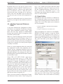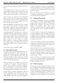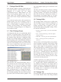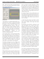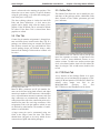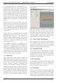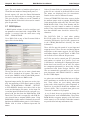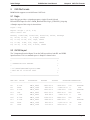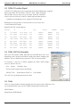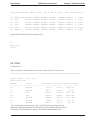
1
Index Design
BOM Builder User Manual
Contents
Contents
1
Introduction . . . . . . . . . . . . . . . . . . . . . . . . . . . . . . . . . . . . . . . . . . . . . . . . . . . 1
Overview . . . . . . . . . . . . . . . . . . . . . . . . . . . . . . . . . . . . . . . . . . . . . . . . . . 1
Input Data Overview . . . . . . . . . . . . . . . . . . . . . . . . . . . . . . . . . . . . . . . . . . . . 2
Output Data Overview . . . . . . . . . . . . . . . . . . . . . . . . . . . . . . . . . . . . . . . . . . . 3
Using Dynamic .DLLs . . . . . . . . . . . . . . . . . . . . . . . . . . . . . . . . . . . . . . . . . . 3
Main Screen . . . . . . . . . . . . . . . . . . . . . . . . . . . . . . . . . . . . . . . . . . . . . . . . 4
Assembly View. . . . . . . . . . . . . . . . . . . . . . . . . . . . . . . . . . . . . . . . . . . . . . . 4
BOM Builder Does Not: . . . . . . . . . . . . . . . . . . . . . . . . . . . . . . . . . . . . . . . . . . 5
Installing . . . . . . . . . . . . . . . . . . . . . . . . . . . . . . . . . . . . . . . . . . . . . . . . . . 5
2
Input Parts Lists . . . . . . . . . . . . . . . . . . . . . . . . . . . . . . . . . . . . . . . . . . . . . . . . 7
PADs .ASC Format . . . . . . . . . . . . . . . . . . . . . . . . . . . . . . . . . . . . . . . . . . . . 7
Schematic Input . . . . . . . . . . . . . . . . . . . . . . . . . . . . . . . . . . . . . . . . . . . . . . 7
PADs Netlist . . . . . . . . . . . . . . . . . . . . . . . . . . . . . . . . . . . . . . . . . . . . . . . . 8
IPL_xxx.dll Routines . . . . . . . . . . . . . . . . . . . . . . . . . . . . . . . . . . . . . . . . . . . 8
Import Example . . . . . . . . . . . . . . . . . . . . . . . . . . . . . . . . . . . . . . . . . . . . . . 8
Part Selection. . . . . . . . . . . . . . . . . . . . . . . . . . . . . . . . . . . . . . . . . . . . . . . . 9
New Part Creation . . . . . . . . . . . . . . . . . . . . . . . . . . . . . . . . . . . . . . . . . . . . 10
Part List Summary . . . . . . . . . . . . . . . . . . . . . . . . . . . . . . . . . . . . . . . . . . . . 11
3
Reading Gerber Images . . . . . . . . . . . . . . . . . . . . . . . . . . . . . . . . . . . . . . . . . . . . 13
Selecting Layers - Read . . . . . . . . . . . . . . . . . . . . . . . . . . . . . . . . . . . . . . . . . 13
Align Gerber Layers . . . . . . . . . . . . . . . . . . . . . . . . . . . . . . . . . . . . . . . . . . . 13
Read Gerber Example . . . . . . . . . . . . . . . . . . . . . . . . . . . . . . . . . . . . . . . . . . 14
4
XYRS & Placement Data . . . . . . . . . . . . . . . . . . . . . . . . . . . . . . . . . . . . . . . . . . . 17
XYRS .DLL Routines . . . . . . . . . . . . . . . . . . . . . . . . . . . . . . . . . . . . . . . . . . 17
Read XYRS Example . . . . . . . . . . . . . . . . . . . . . . . . . . . . . . . . . . . . . . . . . . . 18
XYRS Adjustments . . . . . . . . . . . . . . . . . . . . . . . . . . . . . . . . . . . . . . . . . . . . 18
Adjusting Component Reference Points . . . . . . . . . . . . . . . . . . . . . . . . . . . . . . . . . 19
Board Outline . . . . . . . . . . . . . . . . . . . . . . . . . . . . . . . . . . . . . . . . . . . . . . . 19
Manual Placement . . . . . . . . . . . . . . . . . . . . . . . . . . . . . . . . . . . . . . . . . . . . 20
Verifying Placements . . . . . . . . . . . . . . . . . . . . . . . . . . . . . . . . . . . . . . . . . . . 20
XYRS Summary . . . . . . . . . . . . . . . . . . . . . . . . . . . . . . . . . . . . . . . . . . . . . 20
5
Package Select & Editor . . . . . . . . . . . . . . . . . . . . . . . . . . . . . . . . . . . . . . . . . . . 23
Pick A Package Screen
. . . . . . . . . . . . . . . . . . . . . . . . . . . . . . . . . . . . . . . . . 23
Page I
Contents
BOM Builder User Manual
Index Designs
Package Editor . . . . . . . . . . . . . . . . . . . . . . . . . . . . . . . . . . . . . . . . . . . . . . 23
Package Tab. . . . . . . . . . . . . . . . . . . . . . . . . . . . . . . . . . . . . . . . . . . . . . . . 23
Pins Tab . . . . . . . . . . . . . . . . . . . . . . . . . . . . . . . . . . . . . . . . . . . . . . . . . . 25
Outline Tab . . . . . . . . . . . . . . . . . . . . . . . . . . . . . . . . . . . . . . . . . . . . . . . . 25
PCB Pads Tab. . . . . . . . . . . . . . . . . . . . . . . . . . . . . . . . . . . . . . . . . . . . . . . 25
Paste Tab . . . . . . . . . . . . . . . . . . . . . . . . . . . . . . . . . . . . . . . . . . . . . . . . . 26
Color Control Check Boxes . . . . . . . . . . . . . . . . . . . . . . . . . . . . . . . . . . . . . . . 26
Description Field . . . . . . . . . . . . . . . . . . . . . . . . . . . . . . . . . . . . . . . . . . . . . 26
Toe Positions . . . . . . . . . . . . . . . . . . . . . . . . . . . . . . . . . . . . . . . . . . . . . . . 26
Pin Names . . . . . . . . . . . . . . . . . . . . . . . . . . . . . . . . . . . . . . . . . . . . . . . . . 26
6
Export & Reports . . . . . . . . . . . . . . . . . . . . . . . . . . . . . . . . . . . . . . . . . . . . . . . 29
OrCAD Update Export . . . . . . . . . . . . . . . . . . . . . . . . . . . . . . . . . . . . . . . . . . 29
Excel CSV Export . . . . . . . . . . . . . . . . . . . . . . . . . . . . . . . . . . . . . . . . . . . . 29
Parts & Vendors Export . . . . . . . . . . . . . . . . . . . . . . . . . . . . . . . . . . . . . . . . . 29
User Files . . . . . . . . . . . . . . . . . . . . . . . . . . . . . . . . . . . . . . . . . . . . . . . . . 29
Export Netlist to PCB . . . . . . . . . . . . . . . . . . . . . . . . . . . . . . . . . . . . . . . . . . 30
Decal Map Table . . . . . . . . . . . . . . . . . . . . . . . . . . . . . . . . . . . . . . . . . . . . . 30
Purchasing BOM Report . . . . . . . . . . . . . . . . . . . . . . . . . . . . . . . . . . . . . . . . . 30
Assembly BOM . . . . . . . . . . . . . . . . . . . . . . . . . . . . . . . . . . . . . . . . . . . . . . 31
Kitting Labels . . . . . . . . . . . . . . . . . . . . . . . . . . . . . . . . . . . . . . . . . . . . . . . 31
Board Image . . . . . . . . . . . . . . . . . . . . . . . . . . . . . . . . . . . . . . . . . . . . . . . 31
Smart .PDF . . . . . . . . . . . . . . . . . . . . . . . . . . . . . . . . . . . . . . . . . . . . . . . . 32
Set Default Printer . . . . . . . . . . . . . . . . . . . . . . . . . . . . . . . . . . . . . . . . . . . . 32
7
Import Function . . . . . . . . . . . . . . . . . . . . . . . . . . . . . . . . . . . . . . . . . . . . . . . . 33
MRP Data . . . . . . . . . . . . . . . . . . . . . . . . . . . . . . . . . . . . . . . . . . . . . . . . . 33
Parts & Vendors Import . . . . . . . . . . . . . . . . . . . . . . . . . . . . . . . . . . . . . . . . . 33
BOM Compare . . . . . . . . . . . . . . . . . . . . . . . . . . . . . . . . . . . . . . . . . . . . . . 34
Excel .CSV and .TXT Import . . . . . . . . . . . . . . . . . . . . . . . . . . . . . . . . . . . . . . 35
8
Misc Function . . . . . . . . . . . . . . . . . . . . . . . . . . . . . . . . . . . . . . . . . . . . . . . . . 37
System Options . . . . . . . . . . . . . . . . . . . . . . . . . . . . . . . . . . . . . . . . . . . . . . 37
Delete Functions . . . . . . . . . . . . . . . . . . . . . . . . . . . . . . . . . . . . . . . . . . . . . 38
Renumber . . . . . . . . . . . . . . . . . . . . . . . . . . . . . . . . . . . . . . . . . . . . . . . . . 38
Package Utilities . . . . . . . . . . . . . . . . . . . . . . . . . . . . . . . . . . . . . . . . . . . . . 38
AOT Files . . . . . . . . . . . . . . . . . . . . . . . . . . . . . . . . . . . . . . . . . . . . . . . . . 39
Board Information . . . . . . . . . . . . . . . . . . . . . . . . . . . . . . . . . . . . . . . . . . . . 39
Page II
Index Design
BOM Builder User Manual
Contents
BOM Options . . . . . . . . . . . . . . . . . . . . . . . . . . . . . . . . . . . . . . . . . . . . . . . 40
9
CAD File Formats. . . . . . . . . . . . . . . . . . . . . . . . . . . . . . . . . . . . . . . . . . . . . . . 41
Eagle . . . . . . . . . . . . . . . . . . . . . . . . . . . . . . . . . . . . . . . . . . . . . . . . . . . 41
OrCAD Layout . . . . . . . . . . . . . . . . . . . . . . . . . . . . . . . . . . . . . . . . . . . . . . 41
PADs XY Location Report . . . . . . . . . . . . . . . . . . . . . . . . . . . . . . . . . . . . . . . . 42
PADs .ASC File Generation . . . . . . . . . . . . . . . . . . . . . . . . . . . . . . . . . . . . . . . 42
Protel . . . . . . . . . . . . . . . . . . . . . . . . . . . . . . . . . . . . . . . . . . . . . . . . . . . 42
PCAD . . . . . . . . . . . . . . . . . . . . . . . . . . . . . . . . . . . . . . . . . . . . . . . . . . . 43
Ultiboard . . . . . . . . . . . . . . . . . . . . . . . . . . . . . . . . . . . . . . . . . . . . . . . . . 44
Graffy . . . . . . . . . . . . . . . . . . . . . . . . . . . . . . . . . . . . . . . . . . . . . . . . . . . 44
Allegro . . . . . . . . . . . . . . . . . . . . . . . . . . . . . . . . . . . . . . . . . . . . . . . . . . 45
Proteus . . . . . . . . . . . . . . . . . . . . . . . . . . . . . . . . . . . . . . . . . . . . . . . . . . 45
10 Package Names . . . . . . . . . . . . . . . . . . . . . . . . . . . . . . . . . . . . . . . . . . . . . . . . 47
Package Descriptions . . . . . . . . . . . . . . . . . . . . . . . . . . . . . . . . . . . . . . . . . . . 47
Package Name . . . . . . . . . . . . . . . . . . . . . . . . . . . . . . . . . . . . . . . . . . . . . . 47
Dimension Convention . . . . . . . . . . . . . . . . . . . . . . . . . . . . . . . . . . . . . . . . . . 47
Gull Wing & QFP. . . . . . . . . . . . . . . . . . . . . . . . . . . . . . . . . . . . . . . . . . . . . 47
Industry Standard Styles . . . . . . . . . . . . . . . . . . . . . . . . . . . . . . . . . . . . . . . . . 48
BGA, Connector, SOJ and PLCC . . . . . . . . . . . . . . . . . . . . . . . . . . . . . . . . . . . . 48
LCC, LCQ and QFN . . . . . . . . . . . . . . . . . . . . . . . . . . . . . . . . . . . . . . . . . . . 48
Inductors . . . . . . . . . . . . . . . . . . . . . . . . . . . . . . . . . . . . . . . . . . . . . . . . . 48
Functional Names. . . . . . . . . . . . . . . . . . . . . . . . . . . . . . . . . . . . . . . . . . . . . 48
11 Keyboard Shortcuts . . . . . . . . . . . . . . . . . . . . . . . . . . . . . . . . . . . . . . . . . . . . . . 49
Main Tree Screen . . . . . . . . . . . . . . . . . . . . . . . . . . . . . . . . . . . . . . . . . . . . . 49
Read Gerbers Screen . . . . . . . . . . . . . . . . . . . . . . . . . . . . . . . . . . . . . . . . . . . 49
Pick A Package Screen . . . . . . . . . . . . . . . . . . . . . . . . . . . . . . . . . . . . . . . . . . 49
Package Editor Screen . . . . . . . . . . . . . . . . . . . . . . . . . . . . . . . . . . . . . . . . . . 50
Assembly View . . . . . . . . . . . . . . . . . . . . . . . . . . . . . . . . . . . . . . . . . . . . . . 50
12 INI File Variables . . . . . . . . . . . . . . . . . . . . . . . . . . . . . . . . . . . . . . . . . . . . . . . 51
Parameter Definitions. . . . . . . . . . . . . . . . . . . . . . . . . . . . . . . . . . . . . . . . . . . 51
Page III
Index Designs
1
BOM Builder User Manual
Introduction
Chapter 1 Introduction
1.1 Overview
BOM Builder is a software tool used to prepare
electronic component data for automated assembly.
This tool is design for use by circuit designers who
design circuits and who are responsible for the realization of the final assemblies. Additional features
within BOM Builder support component selection,
schematic to PCB translation and purchasing functions. Control is provided for reuse of existing component data, the incorporation of new component
and the control of design variations. BOM Builder
eliminates the need for schematic library attributes
and allows PCB decal definitions to be easily linked
with purchasing database systems.
The basic idea is quite simple, BOM Builder is a
tool that collects a "Parts List" from a schematic report or spread sheet BOMs and associates that data
with physical packages and their X/Y placement on
a PCB surface. Several additional data items are
collected and merged with this list:
BOM Builder provides the required link to pass
data to automated assembly. Index Designs provides data libraries making BOM Builder a unique
tool for preparing assembly data.
• Indicators for Through Hole, Machine and Hand
• Similar parts are merged into Line Items in
preparation for Pick and Place setup.
• STUFF and NO STUFF status is provided to
support construction of Product Variations.
• X, Y Rotations and Side (TOP or BOT) status
(XYRS Information) for Pick and Place.
Placed Components.
With a parts list and all the component data present
the next questions is "Is All The Data Right"? BOM
Builder is very unique in that it presents all this data
as a completed assembly image. Using a custom
Gerber Reader and package graphic libraries, BOM
Builder show the resulting data as a final board im-
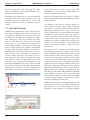
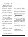
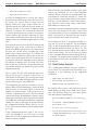
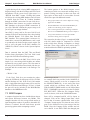
BOM Builder Data Flow
Input Parts List: Convert Raw Parts List to a Structured BOM with Production Control Data
BOM Builder
Read, Process &
Clean
Input Parts List
using IPL_xxx.dll
Raw Input: Schematic Capture,
PCB Design or Spread Sheet
Read and process using approiate
.dll input routine.
Generation of Structured BOM
using "Universal" .BMB format.
X, Y, Rotate and Side (XYRS) Data Merged with Advanced Assembly Package Library
BOM Builder
Read and Adjust
X,Y Rotation, Side
using XYRS_xxx.dll.
Merge of Structured BOM with
Apply "Pick and Place" data from PCB "Ready to Build" BOM with both
Advanced Assembly Package Database. design tools with BOM and Packages. Purchasing and Manufacturing data.
Page 1
Chapter 1 Introduction
BOM Builder User Manual
IndexDesigns
age. This image allows the "Form and Fit" of the
various components to be checked BEFORE an actual bare PCB is fabricated.
cesses. Errors detected while a job is "ON THE
MACHINE" are very expensive. BOM Builder reduces the number of such errors.
The final result of this process is a set of production
documents with all the data required to drive the
manufacturing process. Data can be viewed and
checked before bare PCBs are fabricated or purchased.
Sorting of components into "Line Items" is a fundamental requirement for both manufacturing and purchasing functions.
1.2 Input Data Overview
BOM Builder automatically sorts components into
Line Items and displays the result in a multi-level
tree structure. Software logic identifies line items
by analyzing the Reference Designators, Component Values and, if they are provided, Part Numbers. As Line Items are formed from the input
"Parts List" it is very common that errors are detected. Many BOMs are constructed by hand using
Excel or other spread sheet programs. Such BOMs
are often filled with errors and data inconsistencies.
BOM Builder includes logic that detects input errors, provides a list, and allows an operator to
quickly identify and correct the errors. If two or
more parts have the same Part Number but they
have different Values or Descriptions then "Line
Item Errors" are reported. If Part Numbers are not
provided BOM Builder will sort by Value and PCB
Decal. Errors will also be generated if differences in
Descriptions is detected. Accurate formation of
Line Items is crucial for automated assembly pro-
The number of line items in a project directly affects assembly machine setup as each component
type requires a separate machine feeding location.
Purchasing departments also require a list of required components in line item format. The number
of BOM line items directly effects the effort required to purchase material and the effort of kitting
components for the assembly process. Setup costs
dominate low volume assembly costs and line item
counts are the key contributor. Good engineering
practices will always attempt to reduce the Line
Item counts.
The concept of X, Y, Rotation and Side data being
used for assembly is easily visualized. The need for
Stuffed, Machine and Hand assembly data is not as
obvious until the entire assembly process is considered. A kit of components must be sorted such that
the various types of components arrive at the proper
workstations. None of the Through Hole parts are
required at the pick and place machine. Since some
SMT parts can not be machine placed they must be
hand placed BEFORE the solder reflow process.
Through Hole part mounting is accomplished AFTER both top and bottom SMT (Machine and Hand)
at yet another workstation. The cost for Hand and
Through Hole assembly is much higher than SMT
machine assembly and these counts are very important when computing assembly cost.
BOM Builder provides several Manufacturing Controls along with controls for BOM generation and
PCB design. It is very common for parts to exist independently in the schematic, PCB design or BOM.
Structured BOM.
Page 2
Index Designs
BOM Builder User Manual
These controls identify how component data is used
and allows data to be transferred to various
company departments in an automated manner.
Chapter 1 Introduction
• BOMs sorted per Assembly step. Through Hole
parts are directed to Through Hole work stations,
SMT parts go to the Pick and Place.
• Low cost stencil and solder paste dispensing.
• Eliminate random errors associated with hand
assembly.
Manufacturing Controls
A fundamental problem with many schematic capture and PCB design tools is they do not consider
the various types of data required for assembly. It
is very common for a single schematic and PCB design to be used for a number of different assembly
variations. In each variations of the design it is the
number and types of components installed which is
different. BOM Builder provides the ability to construct these product variations from a single set of
schematic and PCB inputs. Since each BOM
Builder variation maintain a complete design database it is always possible to "Back Check" a BOM
to the current CAD data. The ability to verify a variation against CAD design tools is not possible using
spread sheets or other techniques.
1.3 Output Data Overview
Outputs from BOM Builder include PCB Design
data, BOMs for both purchasing and production,
and assembly documentation for assembly and test.
Most important is the ability of Index Designs to
take the final .BMB file and directly drive a SMT
manufacturing process. Advantages of using the
.BMB to drive our automated manufacturing process include:
• Eliminate the need for schematic design libraries
and CAD librarians.
• Eliminate errors associated with manual
programming of Pick and Place equipment.
• Allows usage of cut tape or loose parts.
Although generation of data for automated assembly is very important, BOM Builder can also prepare data for PCB design. Data concerning PCB
footprints, electrical values and company part numbers is typically inserted into schematic through
schematic library attributes. The preparation of
these library attributes is time consuming, expensive and error prone.
BOM Builder eliminates the need to populate these
CAD libraries with data from purchasing, manufacturing and MRP (Material Resource and Planning)
systems. Instead, BOM Builder supports the annotation of circuit components using data from external
software systems using “Point and Click” with a
graphic interface.The result in a significant reduction in CAD library maintenance while quickly generating accurate BOMs for manufacturing. Changes
in MRP, purchasing or manufacturing data do not
require changes in library attributes, BOM Builder
simply reads the new data and makes it available to
circuit designers, synchronization is automatic.
BOM Builder does not require active connections to
advanced “Data Servers” or SQL engines. Software
within BOM Builder sorts tables, forms indexes,
cross links tables and provides all internal data serving requirements. Raw data can simply be transferred as text files using local area networks, CDs
or web browsers. Engineer can exchange simple
files which include all required data.
1.4 Using Dynamic .DLLs
BOM Builder uses dynamically loaded .DLL files
to read user CAD and component data. There are
three major .DLL function and one internal
Microsoft Access connection:
• Input Part List IPL_xxxx.dll
• X,Y Rotate, Side XYRS_xxxx.dll
• MRP Data MRP_xxxx.dll
• Internal links to Parts & Vendors data in
Microsoft Access format.
Page 3
Chapter 1 Introduction
BOM Builder User Manual
Various .dll routines are supplied for each function
and for various CAD systems. For example
IPL_Protel.dll is used to read Input Parts List from
Protel while the XYRS_Layout_Insert.dll is used to
read XYRS data from OrCAD Layout Component
Insertion reports. Additional .dlls are provided for
reading spread sheet data (.CSV format) and simple
text files. BOM Builder stores the selected .dll routines in the output .BMB file. Multiple BOMs from
multiple CAD systems are easily managed using
this technique.
For all IPL_xxx.dlls the required data consists of
Reference Designator, Value, Part Number, PCB
Decal and Description. Only the Reference Designator is required though a structured BOM can not
be built if all the other fields are blank. Typical usage involves using the Reference Designator and
part Value as contains in the original schematic.
Index Designs
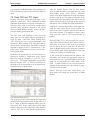
• The Update button will force all the Line Item
Editor fields into the shown reference
designators. A Tree Refresh button can be used to
redraw the Main Tree when required.
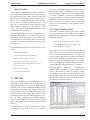
• Along the very bottom are the counts of
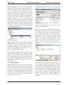
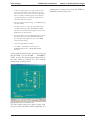
components that fall into various categories.
File SAMPLE3.BMB file has been loaded below
and line items are shown. The line item consisting
of 2 resistors R2 and R3 is selected. Each part is a
100 ohm 1206 resistor and each is to be include in
the BOM and the PCB design. Both are to be placed
by pick and place on the top side and each is a SMT
type component. When doing compares to the
schematic these parts will be verified since each is
checked as being "In The Schematic".
Note: Reference designators must consist of ALPHA characters followed by NUMERIC characters.
Reference designators such as R1, C9999 and
SWIT5 are accepted. Reference Designators such as
C5A, GND, +5 or A1_5 are not accepted.
Data for the XYRS_xxx.dlls requires a Reference
Designator, X Location, Y Location, Rotation, Side
and a PCB Decal. Only the PCB Decal is optional,
all other fields must exist. Each .dll routine will
process it's associated file format and will return the
extracted data to BOM Builder in the proper format.
BOM Builder can populate it's internal search engines with user part data by reading data through
the MRP_xxx.dll routine. Internal code provides
support for reading and writing Parts & Vendors
data structures.
Main Screen
While the various control flags might look like a
significant amount of "Extra" work most will be automatically set as data is read into BOM Builder.
1.6 Assembly View
1.5 Main Screen
A unique feature of BOM builder is the ability to
show how parts will fit on the surface of the final
PCB. Using the Index Designs library of Pick and
Place package models and an internal Gerber
Viewer, BOM Builder can show how packages will
fit before the actual PCB is fabricated.
The BOM builder main screen is show below and is
divided into top and bottom sections.
In addition to simply viewing the BOM data the
user can use the Assembly View to:
• The Main Tree in the top section show a
structured view of line items. Color coding in the
Main Tree view gives an indication of Existing,
New and Unknown parts.
• A Line Item Editor area is at the screen bottom.
This area allows the user to Add, delete or modify
the nature of line items.
Page 4
• Adjust component position and rotation.
• To query a mount location and determine the
RedDes, Value, Desc. and Part Number.
• Identify the line item to which the part belongs
and locate similar parts.
Index Designs
BOM Builder User Manual
• Verify polarized component orientation.
• Verify component fit and PCB Decals.
• Generate "Smart" .PDF containing BOM data
and PCB graphics.
A very important function of the assembly view is
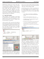
to identify how component leads fit on the copper
and solder paste deposits. Copper is shown in grey
while solder paste is shown in light blue. Package
models from Index Designs show metal lead faces
in RED or BLUE depending on the displayed side.
The ability to visually inspect how a component
lead is positioned in paste and on copper is critically important to product reliability and assembly
yield. Further the setup and programming of automatic assembly equipment is 100% verified.
The ability to automate the collection of assembly
data from schematics, PCB designs, CAD tools or
Spread Sheets and to combine this data with a library of component models is unique. The ability to
drive a automated assembly line with this data is
truly a unique service.
Chapter 1 Introduction
CAD tool libraries. BOM builder is a “Steal the
Data as Required” environment that keeps a record
of what was “Stolen” and allows sharing of the
“Stolen” but organized data.
BOM Builder will operate in a stand alone manner
without a component database. Index Designs provides a limited database of standard parts for companies without internal systems.
1.8 Installing
Installing is very simple, simply download and run
the distribution from www.aapcb.com. If BOM
Builder is already installed it MUST be removed
first. Use the "Remove Programs" function in
Co"Control Panel". If you have made any changes
to the c:\BOM_Bldr\Data\BOM_Bldr.ini file
backup this file first. Also, if custom PACKAGES
have been created backup the Package Data
(PACKAGES - BACKUP PACKAGES) then save
the c:\BOM_Bldr\Data\BOM_Bldr.ini file.
1.7 BOM Builder Does Not:
BOM Builder does not replace the need for an external component database system. BOM Builder
simply organizes external data into a format that allows a rapid association between BOM line items
and external data. BOM Builder maintains these
links in a local database and can exchange these
data structures using simple text files. This process
eliminates the need for extensive attributes within
Page 5
Index Designs
2
BOM Builder User Manual
Input Parts Lists
Schematic capture programs are the preferred
source of part data. Spread sheet are often used but
most spread sheet users generate these list by hand
and the data is often inconsistent or simply in error.
Other source of data include PCB design software
though once again this data may not represent what
is truly required by the schematic designer. In either
case the required data consists of:
Chapter 2 Input Parts Lists
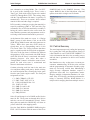
Three fields in the System Options screen allow the
selection of PADs attributes to be used as input for
various BOM Builder fields.
• RefDes: A simple combination of up to 5 letters
followed by a number between 1 and 9999. Valid
examples are C1 and RN5. Invalid examples are
U5A, J1-1 and +5.
• Value: A short text string that provides basic
information about a component. Examples are
10K, .1uf and LM555.
• Part Number: Optional. A company part number
is very useful as it gives exact definition about the
nature of a component
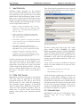
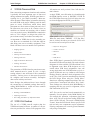
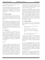
System Options Screen
• Description: Optional. Provides useful
information for assembly, purchasing and test.
BOM Builder will generate default Descriptions.
• PCB Decal: Optional. If available from the
schematic it will assist with forming line items.
PCB Decal is provided my most XYRS input .dlls
and is not required in the parts list.
The above data items provide the information that is
used to form line items. If a Part Number is provided parts with identical Part Numbers will be
merged into a single line item. If parts with identical Part Numbers but different Values or Descriptions are detected BOM Builder to report "Line
Item Errors". The nature of these errors should be
resolved.
2.1 PADs .ASC Format
BOM Builder contain internal logic to read in PADs
.ASC files which are generated by the Mentor
PowerPCB design tool. This type of .ASC file IS
NOT the same as a .ASC netlist file generated by
most schematic capture programs. A PowerPCB
.ASC file contains all the XYRS data, Decal names,
Values and other component attributes. These attributes may or may not contain useful data depending on the quality of the schematic and PCB
libraries.
The above setting will result in the .ASC reader
using attribute "PART NUMBER" for BOM
Builder part numbers while the VALUE, DESCRIPTION, VOLTAGE RATING and TOLERANCE attributes are all merged for use as a Description. This
information is only valid if the PCB designer has
carefully prepared component attributes. This is seldom the case.
As the .ASC file is read two conditions are detected
and the user must indicate how to proceed. These
conditions are:
• New reference designators are detected.
• Should PCB decals be read.
A PCB design may contain many items that are not
found in a final BOM. Examples of these are
mounting and tooling holes. If a BOM Builder file
already has been edited to where it contains only the
required parts then the user does not want the reader
to read in new reference designator. If the user is
starting a new BOM Builder file then reading of all
the reference designators is required.
2.2 Schematic Input
BOM Builder reads parts list information from a
schematic using one of two different input
functions.
Page 7
Chapter 2 Input Parts Lists
BOM Builder User Manual
• FILE - OPEN OTHER - PADs NETLIST
Index Designs
Side" button will result in BOM Builder using the
XYRS_xxxx.dll to read in XYRS data.
• Use of IPL_xxxx.dll routines
2.3 PADs Netlist
The first is a PADs netlist format which has component information in the *PARTS* section. Like the
.ASC reader attributes will be pulled from the
netlist according to the attribute names assigned in
the Systems Options screen. Many schematic capture programs will generate PADs netlists but few
will populate this netlist with component attributes.
PADs netlists are read using the Main Menu sequence FILE - OPEN OTHER - PADS NETLIST.
While a PADs netlist can also be read using .dll
routines the OPEN OTHER - PADS NETLIST allows use of named attributes when collecting data.
See section 2.1 PADs .ASC format for a description
of how this logic operates.
2.4 IPL_xxx.dll Routines
The second method is through a user selected
IPLxxxx.DLL file. There are many different
IPL_xxx.dll files each of which supports the reading of a specific report from a specific schematic
capture program. A single .dll is selected by using a
DOUBLE CLICK on that items field.
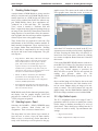
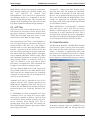
Generic Import Functions
The menus items are generic while the BOM Options setting select a specific .dll routine. The selected routines, as well as all the other BOM
Options are saved in the final .BMB file.
Within the System Options screen ( EDIT - SYSTEM OPTIONS) is a table used to associate component descriptions with reference designators.
When a net list is read the leading ALPHA CHARACTERS of the reference designator are stripped
off and the “Ref. Des. To Type List” is search using
the stripped alpha characters. If a match is found the
“Component Type” text is appended to the description field.
2.5 Import Example
BOM Options .dll Selection
In the above example .dll routines for reading
"OrCAD Layout Component Insertion Reports" are
selected for both IPL (Input Parts List) and XYRS
(X, Y, Rotation and Side) import functions. When
the user selects the generic Import Parts List the
IPL_Layout_Insert.dll will be used. When the user
selects the generic XYRS Import the XYRS_Layout_Insert.dll will be used.
Selecting the "Parts List" menu item will cause
BOM Builder to load the IPLxxx.dll and read in a
parts list using that .dll. Selecting the "X/Y Rot
Page 8
The best description is an example. After starting
BOM Builder use the sequence:
FILE - OPEN OTHER - PADS NETLIST
This sequence will open a dialog box showing a
SAMPLE directory. Open this directory and click
on the SAMPLE.NET file. (A SAMPLE.PDF files
is also located in the SAMPLE directory and it
shows the source schematic.) This .NET file was
constructed in OrCAD Capture using the PAD output format with {Value} in the FOOTPRINT
PROPERTY STRING.
Index Designs
BOM Builder User Manual
When the SAMPLE.NET file is read a structured
BOM tree will be shown in the upper portion of the
Main Screen with several red elements. This tree is
a view showing the various “BOM Line Items”
which are contained in the schematic. Identical
items have been grouped together. Click on the red
“Res (R)” line which will drop open and then click
on the red “(2) 100” line which will also open. As
“BOM Line Items" in the tree are selected detail
about these parts is shown in various fields located
in the Line Item Editor section towards the screen
bottom. This bottom area is where a user edits BOM
line items and where the Update BOM button can
be clicked which will update the BOM database
with Line Item Editor data.
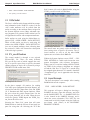
Read of SAMPLE.NET
When schematic data is read, the Reference Designator and Value are used to provide the initial data
concerning a circuit assembly. The key items are
reference designators and component values for
electrical parts. The resulting “Parts List” is the
starting point for BOM generation.
Many companies generate extensive CAD libraries
which include additional data (attributes) about
these parts for use in secondary processes. Examples of these attributes include Company Part Number, PCB Decal, Vendor Numbers and assembly
information. BOM Builder eliminates the need for
these libraries.
2.6 Part Selection
With SAMPLE.NET read in all parts are shown as
RED since most fields are undefined. Click on the
“(2) 100” line item under the Res branch and the
Line Item Editor at the screen bottom will show that
R2 and R3 are selected and the current Description
as Res 100. A DOUBLE CLICK on the Description
field will start the search engine with results shown
in the “Part Lookup” screen.
Chapter 2 Input Parts Lists
The top matches (three in this case) are 100 ohm resistors in different sizes. Parts are grouped by the
Results of Search on Res 100
quality of the match. In this case the first 3 items
matched with equal priority.
In the Search Results List DOUBLE CLICK on the
1206 part and the main tree screen is shown with
new information about the selected component in
the Line Item Editor area. Click on the “Update
BOM” button to save the new data for parts R2 and
R3. Notice the R2 - R3 line item are now "White
Coded" since complete engineering data is now
linked. Also notice that both Package and PCB
Decal contain “1206”, the Part Number is
“SMR-5%-1206-100” and the Description is quite
detailed.
"White Coding" of R2 and R3
Annotation of component using this technique is a
very powerful and unique function of BOM
Builder. Just as different schematics and PCB tools
are interfaced to BOM Builder through the use of
.dll routines, the data which drive the search engine
can be read from a user databases through .dll routines. With this ability to rapidly associate data
between line items and a company database the
need to place attributes in schematic libraries is
eliminated.
Page 9
Chapter 2 Input Parts Lists
BOM Builder User Manual
BOM Builder eliminates the need for these attributes by allowing an engineer to “Steal” data from
external data sources AFTER the schematic is complete. Schematic generation is much faster and data
more accurate since part assignment is a “Post”
schematic design process. Engineers can concentrate on connectivity with support staff assisting
with most part assignments. BOM Builder encourages data reuse by providing a means for collecting
information about new components.
2.7 New Part Creation
When designing a circuit assembly new parts must
be introduced into the engineering process. BOM
Builder provides a means for identifying new components and allowing a project to continue until
new part numbers are generated.
Index Designs
ages” list. You will see 0603 filed into the Package
field in the line item editor and at the same time the
"Part Type" field will change to SMT.
At this point you have selected a new package for
R1 but the BOM has not yet been updated. Click on
the "UpDate BOM" button in the Line item editor.
Several actions will take place when UpDate BOM
is clicked.
• A User Table is searched for any PCB Decal
names that have been associated with the 0603
package.
• Either a matching PCB Decal name or the
Package name is filled into the PCB decal Field.
• The BOM database is updated from the fields in
the Line Item Editor area.
• R1 becomes "Green Coded". All the required data
Click on the “R1 1K” line item in the main tree
which shows R1 and Res 1K in the Line Item Editor
fields. Part Number, PCB Decal and Package are all
UNASSIGNED. DOUBLE CLICK on the “Package” field which will open the Pick A Package
screen and start the package search engine. Move
the windows as shown below
is present for PCB design and manufacturing.
Purchasing data is not available as no Part
Number has been assigned. (New parts don't have
numbers.)
The resulting screen is shown below.
Green Coded Part after Update BOM
BOM Builder allows construction of line items
which are “Technically Incomplete” yet it allows
the design and manufacturing process to continue.
The GREEN indicates the PCB process can continue but there are open issues with this line item.
Selecting a Package for a New Component
You might need to click on the "Search" button to
execute the search. Click on the: “Res Cap Inductor
Chip 0603 1608 SMT” line in the “Available PackPage 10
With the GREEN “R1 1K” item selected click on
the STUFFED check box (which will remove the
check mark) then click on the “Update BOM” button. This identifies that this part is not to be stuffed
and causes the color to change to grey. Additional
check boxes allow parts to be independently marked
as IN BOM, IN PCB Design or included IN SCHEMATIC checking. BOM Builder includes logic for
comparing different BOM versions or comparing
Index Designs
BOM Builder User Manual
new schematics to existing BOMs. The “ In SCH”
bit is used in this checking logic. There is also a
"Part Type" field which allows a part to be marked
as SMT or Through Hole (THT). This setting, along
with the Top and Bottom side status, is typically set
automatically. There are occasions where manual
control of these and other flags is required.
Chapter 2 Input Parts Lists
SAMPLE1.bmb in the SAMPLE directory. This
output .BMB file has all the linked data, setup and
options recorded in a single text file format.
PCB Assembly techniques require that material be
sorted by technology (SMT or THT) and side (Top
or Bottom). Key to efficient and timely assembly is
having the correct material at the correct work stations. Machine operators and programmers need exact listings of the material that must be processed.
At the bottom of the main tree screen is a “Design
Mode” group of radio button. Click on the PCB
(PCB Design Mode) button and coded parts turn to
Yellow. While these parts have PCB decals assigned there are no corresponding entries in the
User Decal Table. The Yellow indicates that there
may be a problem with the PCB decal assignments.
The color of the line items is different for different
design phases. PCB is associated with PCB Design
while PnP (Pick N Place) is associated with manufacturing processes. Also notice that when a
“Design Mode” button is clicked the count of component for each color state is recalculated and
shown in the bottom color boxes.
Continue selecting each line item in the main tree
view and then naming each part by double clicking
on each Description then selecting the below parts
from the part search engine results. The final part
assignments will be:
C1
C2
P1
JP1
R1
R2
R3
Q1
SMC-CER0603-.1UF-50V
SMC-TANT-10UF-6.3V-A
CON-09-D-MALE-RA-.318
POST-025-1X2
SMR-5%-0603-1.0K
SMR-5%-1206-100
SMR-5%-1206-100
SMQ-2N3904
SAMPLE1.BMB Final Status
2.8 Part List Summary
The most important aspect of reading the input parts
list is getting the Value and Descriptions correct. If
a Part Number is read IT MUST BE CORRECT. It
is this information that drives the assembly process
and bad data is guaranteed to deliver miss-stuffed
assemblies.
Part Numbers are a key to data reuse. Accurate procurement, manufacturing, PCB foot print selection
and the programming of automatic assembly equipment rely on having verified data. Maintaining a
single accurate component database requires a
sginificant effort that few organizations master.
Keeping multiple independent databases for schematic entry, PCB design, purchasing and manufacturing is extremely difficult. BOM Builder is a
unique tool for merging data from multiple sources.
Select P1 and change it to be HAND stuffed, do the
same for JP1. These parts are through hole devices
and they can not be automatically placed. Unless
these parts are marked as HAND they will show as
yellow in the PnP color mapping mode.
Save the final BOM as SAMPLE1.BMB using the
FILE - SAVE AS menu. Edit the name of the file to
Page 11
Index Designs
3
BOM Builder User Manual
Reading Gerber Images
A major feature of BOM Builder is giving users the
ability to visualize and verify BOM and physical assembly data. Just as a PCB design tool shows how
traces will be rendered into Gerber fies (then to copper) BOM Builder shows how components are
"rendered" on a Pick and Place. The "Assembly
View" screen is actually a "Software Pick and
Place" engine that shows physical package data on
an image of the final PCB. Generation of that PCB
image requires of several Gerber files, the construction of graphic data for each layer and the alignment
of those layers into a color graphic image.
Three Gerber files are required for each side (Top
and Bottom) of the PCB that contains machine or
hand mounted components. These required layers
are Copper, Solder Paste and Silkscreen. Reading
of Gerber data is complicated by the need to align
the layers and locate actual components. The general steps are:
• Align Gerbers: While many CAD tools will output
Gerber data relative to the same X,Y location
some uneducated users still "Center" Gerber
plots. This results in random offsets which
requires all layers to be manually align. This
would not be a problem except these same few
"Designers" fail to place a consistent object in all
the layers to enable manual alignment.
• Mirror or Rotate: All Gerber files should be
provided as "View Through the Top". The
orientation must be the same as the component
location (XYRS) information.
• Set Component X,Y Reference:The 0,0 point for
the component XYRS data must be defined. Often
this is 0,0 but not always.
BOM Builder reads Gerber data and generates internal display lists for graphic display. RS-274-X
polygons are rendered as "Cross Hatch" area and
"Clear" polygons are ignored.
3.1 Selecting Layers - Read
Selecting the BOARD - READ GERBER menu
opens two windows, Read Gerber and X,Y
Assignment. These screens are shown below.
The drop down list in the Select Layer control allows the user to select a layer for data transfer.
When a layer is selected any Gerber data that already exists for that layer will be placed in the grey
Chapter 3 Reading Gerber Images
graphic screen. The mouse can be used to click and
select graphic items from that screen. As items are
Select Gerber layer
select their X Y locations are placed in the X,Y Assignment screen and the selected item is highlighted
in white. Pressing the Delete Key will delete a selected item. Line items can be selected by clicking
on a center or endpoint. Round items are selected at
their center.
Click on the BROWSE READ button to read an external RS-274-X Gerber file. Note that a layer must
be selected before BROWSE READ can be selected. Very limited support is provided for
RS-274-D files as special .dll files are required for
reading
the
aperture
tables.
See
file
c:\BOM_Bldr\IntfTools\Gerb_Apertures.txt for details.
Once read the image will be fitted to the screen and
a blue cross will show the 0,0 if this location is fitted on screen. Buttons allow an image to be mirrored or rotated. The SAVE button will copy the
graphic image into the BOM Builder database and
the Gerber image can then be saved with the BOM.
3.2 Align Gerber Layers
The X,Y Assignment screen will accept X and Y
parameters and will use these to modify the current
Gerber image or database according to a series of
check boxes. These check boxes control how the X
Y values are used to midify Top and Bottom side
settings.
• Align Current Gerber
• Define Component 0,0 Reference Point
Page 13
Chapter 3 Reading Gerber Images
BOM Builder User Manual
• Define Board Fiducials 1 and 2
• Define Board Test Position
In order for BOM Builder to overlay the Copper,
Solder Paste and Silkscreen Gerber files into a single image, the various Gerber Layers must be
aligned. When the Align Gerber check box is
checked, and the user clicks the Execute button, the
currently selected X Y location is subtracted from
Gerber X Y locations. This results in the selected X
Y location becoming the new Gerber 0,0 location.
(Do not confuse this with the Component X Y Reference Point.) Unaligned gerbers files can be easily
aligned if there is a common graphic object in each
layer.
Each time the Align Current Gerber is checked and
processed a copy of the selected X Y location is
saved in the BOM Options screen in a Gerber Offsets area. Also in that area is a Enable flag. If the
Enable flag is checked then these X Y offsets will
be automatically applied to Gerber files as they are
read in. Since most Gerber files are constructed using identical offsets this automatic usage simplifies
the reading of multiple files. If Gerber Files have
been "Centered" (which is a very bad idea) then the
user should uncheck the Enable flag and preform
alignment manually.
Once a gerber file has been read and adjusted it
must be saved to the currently selected layer by
clicking the SAVE button. This saved gerber image
will be saved with other BOM data and will eventually be written into the final .BMB file.
The Component X,Y Reference location is very important. When XYRS information is read from PCB
CAD tool files it is this point which is used as the
graphic 0,0 reference point. If this point is not set
correctly components can not be correctly located
on the board image. BOM Builder contains "Angle,
Offset and Translation" (AOT) logic that will adjust
for XYRS data not being defined for the component
centroid. In order for this logic to operate correctly
the Component Reference Point must be set correctly. This reference location will be marked with a
red + sign.
Index Designs
Each PCB side with machine mounted parts must
include the definition of two board alignment
fiducials. When a check box is checked and the Execute button is clicked the selected X Y values will
be used for the corresponding fiducial X,Y location.
Fiducial 1 will be drawn as a small circle with a +
sign, fiducial 2 will be draw using a small circle.
Both makers are drawn in red.
Automatic placement equipment requires a location
where the board height can be safely sensed. This
test position must be clear of components and large
holes. The Board Test Position sets this location
and it is marked with a small circle and X.
At the bottom of the X,Y Assignment window is a
flag and X,Y field for both the Top and Bottom
sides. As the Component Reference point is set for
each side the associated check box will be set. The
X,Y location from the Gerber object will be placed
in the X and Y fields. The 0,0 of a Gerber is related
to the Component Reference Point through these X
Y locations. The display of these locations can help
when unknown Gerber files and XYRS files must
be debugged.
3.3 Read Gerber Example
The C:\BOM_Bldr\SAMPLE directory contains a
set of Gerber files generated from PowerPCB. Also
included is a file containing all the component
XYRS data.
• ART01.PHO (Top Side Copper)
• SST0126.PHO (Top Side Silkscreen)
• SMD0123.PHO (Top Side Solder Paste)
By reading these gerbers and position text into
BOM Builder an image of the PCB can be generated. The following steps will read these Gerber
files and construct a board image.
• Open the SAMPLE1.BMB file created in Chapter
2.
• Use BOARD - READ GERBER to open the
Gerber Read screen.
• Use Layer Select to select Top Copper.
• Click the Browse/Read button and navigate to the
If the Component Reference Point is not set correctly any attempts to use AOT logic or Group
Moves will fail. The Component 0,0 reference point
must be accurately defined.
Page 14
c:\BOM_Bldr\BOMs\Sample directory and Open
the ART01.PHO file.
Index Designs
BOM Builder User Manual
• In the X,Y Alignment screen enter 1000 in both
the Selected X and Selected Y fields or click on
the lower left corner of the lower left board edge
mark. (A 1000 x 1000 mil offset was used when
creating this Gerber.) Check the Align Gerbers
check box and click Execute.
Chapter 3 Reading Gerber Images
components are located at 0,0 since the XYRS information has not yet been read.
• Save the Copper Gerber image to the BOM using
the Save button.
• Use Layer Select to select the Top Solder Paste.
Use Browse/Read to Open file SMD0123.PHO.
This file was automatically aligned so save to the
BOM using the Save button.
• Use Layer Select to select Top Silkscreen. Use the
Browse/Read to Open file SST0126.PHO. This
was automatically aligned so save to the BOM
using the Save button.
• Close the Read Gerber window.
• Use FILE - SAVE AS to save the file as
SAMPLE2.bmb in the c:\BOM_Bldr\Sample
directory.
At this point the board Gerber files have been read
into the BOM. Use the BOARD - ASSEMBLY
VIEW to view the merged gerbers along with all
the parts sitting at location 0,0. The resulting
merged image is shown below.
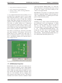
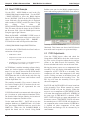
Sample2.bmb Gerber read Parts at 0,0
The above image shows the Copper in gray, Silkscreen in yellow and Solder Paste in light blue. All
Page 15
Index Designs
4
BOM Builder User Manual
XYRS & Placement Data
Data concerning component locations and rotations
is probably the most important type of data used
during automated assembly. Without good data everything else is just "Hand Assembly". Most machine operators "Hand Adjust" placement data using
an actual PCB as the target. Nothing could be more
prone to errors. Silkscreens which direct hand
placement are often removed from pads and vias if
the silkscreen even exists at all. Camera views on
machines are limited and working with a limited
view can result in errors. BOM Builder contains the
tools to "Get it Right" at design time which improves data accuracy and reduces assembly time.
As important as XYRS data is to the assembly process there are no standards for CAD data input or
data being sent out to assembly equipment. Combined with these issues are another set of problems:
Chapter 4 XYRS & Placement Data
.dll routines are easily written if the CAD data format is known.
A single XYRS_xxxx.dll routine is selected through
the BOM Options screen. A DOUBLE CLICK on
the XYRS Input Processor field will allow the user
to select the appropriate XYRS_xxxx.dll file.
BOM Options Fields for .dll Selection
When the main menu "IMPORT - X/Y Rot Side"
item is clicked, the above pre-selected .dll file will
be used to read several pieces of data.
• Reference Designator
• Stuffing Options
• X and Y Location
• Mount Order
• Rotation
• Missing Orientation Marks
• Side
• Missing Fiducials
• PCB Decal
• Different Rotation Directions
• Package Variations
• Machine Orientation
The generation of XYRS data for parts that are machine mounted must be sorted by side. A single
sorting scheme is not sufficient to drive automated
assembly. Various pieces of data must be provide
for complete and accurate assembly. Incomplete
data results in delays and errors.
Index Designs has addressed these issues through
the construction of standard package data and by
coding BOM Builder to record and reuse rotation
data. This process consists of:
• Reading CAD XYRS Data
• Adjusting Positions
• Recording and Reuse of Adjustment Data
4.1 XYRS .DLL Routines
The use of a XYRS_xxxx.dll requires that the
XYRS data format be known. A number of .dll routines are provided for various CAD programs. New
Since XYRS data is generated by PCB CAD tools
the actual PCB Decal associated with each reference
designator is often available. PCB Decal data is key
to alignment reuse. Most PCB designers are very
careful about PCB decal assignments since one
wrong decal and a new PCB fabrication cycle is required. PCB decals are very similar to ndex Designs
Package libraries and these decal assignments serve
as the "Key Link" between manufacturing data and
the PCB design. When using the "Group Move"
function to adjusting component positions this correction data is associated with theses "Key Links".
These linkages are collected while BOM Builder is
operating and they are saved in Alignment, Offset
and Translation (AOT) files.
AOT files can be read and saved automatically or
manually. Several options in the BOM Builder .ini
file controls this operation. Adjustment data from
these .AOT files are used when reading XYRS data
from a PCB CAD tool. The result is BOM Builder
"Learns" about the PCB decals from a specific CAD
tool and only new components require adjustment.
Existing components are correctly placed automatically using existing data.
Page 17
Chapter 4 XYRS & Placement Data
BOM Builder User Manual
4.2 Read XYRS Example
Use the FILE - OPEN BOM to read in the file:
c:\BOM_Bldr\Sample\sample2.bmb . Use the EDIT
- BOM OPTIONS to show the BOM Options
Screen. DOUBLE CLICK on the XYRS Input Processor field and a file open dialog box is displayed
with a number of XYRS_xxx.dll files shown. Using
this
dialog
box
select
the
XYRS_PADSXYPositions.dll file then click OPEN.
This file name will then be shown in the XYRS Input Processor field. Close the BOM Option screen
using the upper right X button.
Index Designs
Builder users can view the BOM, component placements and stuffing options BEFORE a bare board is
When the BOARD - ASSEMBLY VIEW screen is
opened all the components can be seen at the 0,0 location. Use the Main Screen FILE - IMPORT X/Y Rot Side to read in PCB position data from:
c:\BOM_Bldr\BOMs\Sample\POSITIONS.txt
Click OK on the "XYRS Unit Select Form" and several action will take place.
• XYRS Data is Read
• Component Locations in the Assembly View
screen are updated.
• A XYRS_Log.txt result file is created and opened
in the default system editor for .txt files.
As XYRS data is read the incoming reference designators are checked against existing BOM components. If a new item is detected in the XYRS data it
is flagged. If a BOM component does not receive
XYRS data then this is noted at the end of the log
text. Missing or extra items could indicate errors
with the Input Parts List.
The resulting Assembly View screen is shown below. In this example, the X,Y locations for the various components will all represented the true
component centroids.
If PCB Decals had been constructed with origins at
pin 1 locations or with rotation orientations different from the Index Designs libraries, the location of
the shown components would be offset.
Use the main menu FILE - SAVE AS to save the
complete database as SAMPLE3.bmb. All Gerber
files, part images, BOM line items are saved in the
.BMB file. When the file SAMPLE3.BMB is
opened the board can be viewed. Using BOM
Page 18
Assembly View After XYRS Read
fabricated. This feature can detect bad PCB decals
that could result in expensive re-spins and delays.
4.3 XYRS Adjustments
Close the XYRS_Log.txt editor and check the
Group Move (GRP Move) check box in the Assembly View screen. If required, adjust the size and positions or the Main Screen and Assembly View
Screen such that both can be seen at the same time.
Moving the mouse cursor over a component in the
Assembly View will display information about that
component. A LEFT CLICK on a Assembly View
component will show that component in the main
screen. Clicking on items in the Main Screen will
select that component in the Assembly View. The
ESC key will cause the Assembly View to again
show all component.
PAGE UP and PAGE DOWN will zoom in and out
of the Assembly View. When zoomed in a mouse
RIGHT CLICK will pan the display. When the
mouse is over a component a CTRL RIGHT CLICK
will rotate that component AND ALL OTHERS of
the same type if GRP MOVE is checked. CTRL
LEFT CLICK will pick up a parts and attached it to
the mouse cursor. CTRL RIGHT CLICK will rotate
the attached part. A LEFT CLICK will drop the cursor component at the current location. If GRP Move
is checked all other components of the same
PCB_Decal and Package will be relocated by he
same amount.
Index Designs
BOM Builder User Manual
Chapter 4 XYRS & Placement Data
Keyboard arrow keys can also be used to move
components. Zoom in and LEFT CLICK on Q1, information about Q1 is shown in the upper right.
Press and hold the ALT key. While the ALT is
down the arrow keys will move Q1 in 1mil increments. If the ALT and SHIFT keys are held down
each arrow key press will move the component by 5
mils.
keys. A ^R (CTRL R) will start a Reference Point
Mode of operation where ALT Arrow keys will adjust the Component Reference Point for the currently viewed side. Adjustments are in 1 mil
increments and holding down the SHIFT key will
move in 5 mil increments.
Do not press and hold the arrow keys down, the automatic key rate might be faster than the board is redrawn.
BOM Builder allows the definition of a Board Outline. Currently this outline serves only as a cosmetic
function, the centering and color control for the Assembly View screen. This outline can be defined in
one of two manners:
4.4 Adjusting Component Reference
Points
As previous mentioned the Component 0,0 Reference Point is very important. The ability to automatically adjust component positions using Group
Move and AOT logic depends on BOM Builder
knowing the reference point for component values
read from CAD tools data.
While any "Good" PCB design will have this point
clearly marked some PCB Designers forget to include this datum. In these cases where it is not possible to set the reference point using something in a
Gerber file it is possible to set these points using the
Assembly View editor.
4.5 Board Outline
• Using the BOARD - DEFINE OUTLINE Main
Menu function
• Using the ^B function in Assembly View
With the SAMPLE3 file loaded use the BOARD DEFINE OUTLINE sequence to open the Define
Outline screen. The top portion of the screen is a
short cut for generating outlines for rectangular and
square boards. The bottom section is a sequence of
X,Y values that make up the points of the board
outline.
If there is a single component where the centroid of
the component is known that component can be
"Placed" and the Component Reference Point set.
Typical components that work with this scheme are
large QFP packages. Any package will work if the
PCB Design has constructed the PCB decal with the
0,0 at the decal center.
Using CTRL ALT LEFT CLICK a part can be
picked up and moved just as if a CTRL LEFT
CLICK had been used. The difference is when the
component is dropped. Dropping the part in this
case does not move the part, instead software computes the X,Y differences and applies this to the
Component Reference Point. The result is the
"Moved" component moves to the correct location
and all other parts move at the same time. It is not
parts being moved only the reference point. A dialog box will ask if these offsets should be used for
both side, the answer is typically yes.
There is one more scheme for adjusting the Component Reference Points which is done using arrow
Outline Dimensions for SAMPLE Board
When the "Create Coordinates" button in the top
section is clicked the bottom section will be populated with a set of X,Y values. The "Create Board
Outline" button at the screen bottom will actually
Page 19
Chapter 4 XYRS & Placement Data
BOM Builder User Manual
generate the outline from the sequence of X,Y locations.
The SAMPLE board is 2.0 inch x 2.0 inch in size
and the numbers can be entered in mils or mm. Any
number with a decimal point is consider mm. Any
number without a decimal point is considered mils.
All X,Y values are referenced to the Component
Reference Point. The user must know the lower left
location and the board size. If the Component Reference Point is not correct the outline will not be
drawn in in the correct position.
With the SAMPLE3 file loaded open the Assembly
View window and notice the tick marks in each
board corner. Also notice the 0,0 reference point in
the lower left. With the Assembly View window selected press a ^B to enter Board Outline Mode.
Using the mouse LEFT CLICK the lower left corner
then LEFT CLICK the upper left corner. A pink line
will be drawn showing the first segment of the new
board outline. Mouse clicks will pick the nearest
point in either of the 3 Gerber layers. The closest
point is used for the X,Y location of a outline
point..Continue by selecting the upper right, then
lower right corners. Press another ^B to end the
Board Outline Mode and the completed image is
displayed.
Save the final image to SAMPLE3.BMB.
4.6 Manual Placement
If a board is relatively small and XYRS data is not
available then parts must be hand located. The Assembly View contain logic and a "Placement Sequence List" to assist with this tedious chore. The
placement list allows a user to zoom in on a section
of the board and then enter a list of components that
can be viewed at that zoom factor.
With the Assembly View window selected enter a
^P (CTRL P) to open the "Placement Sequence"
window. Enter a number of reference designators
with a space between each reference designator.
Press the ENTER key when done. This list of reference designators will be displayed in the lower left.
Press the ESC key and the component for the first
reference designator will be attached to the cursor.
LEFT CLICK will drop this component while
CTRL RIGHT CLICK will rotate the component.
Page 20
Index Designs
When the component is dropped it is removed from
the Placement Sequence List. Pressing the ESC key
will take the next component from the list and that
part can be placed.
This logic allows a user to ZOOM in to a good
working level and then place components without a
lot of ZOOM and PAN operations.
4.7 Verifying Placements
Verification of component placement and orientation is critical for accurate assembly. BOM Builder
contains links between the Main Tree Structured
BOM and the Assembly View screen for "Cross
Probing" type operation. When both of these
screens are positioned on the computer desktop
such that both are visible component checking is
simplified.
A click on a Main Tree line item will highlight the
selected components in the Assembly View. Since
components within a single line item can be located
on different sides of a board there are Red and Blue
indicators in the Assembly View screen to indicate
the counts on each side.
If the user is zoomed in and a single component is
selected, that component will be centered in the Assembly View screen. If more than one component is
selected the midpoint is centered.
When the Main Screen is selected, the arrow keys
will move down tree line items. This movement is
done in a manner that speeds component checking.
At Index Designs this scheme is used to verify that
each part is reasonably placed and the orientation of
polarized parts is correct.
If the user clicks on a component in the Assembly
View screen, information about that component is
placed in the upper left and that component is identified in the Main Screen Tree.
4.8 XYRS Summary
The key to successful automatic assembly is good
data. XYRS data and Component Reference Point
data are typically a "Throw It Over the Wall" issue
for most PCB Designers. But operating in this mode
requires manufacturing people to sometimes guess
about what is required and this leads to errors. As
components become smaller there is less room for
Index Designs
BOM Builder User Manual
Chapter 4 XYRS & Placement Data
reference designators and incomplete data results in
project delays.
BOM Builder contains the tools to automatically
"Get it Right the First Time" but PCB designers
must be aware of the required data.
Page 21
Index Designs
5
BOM Builder User Manual
Package Select & Editor
Index Designs supplies a library of physical package models which are called Packages. All data is
contained in a single text file named
PACKAGEDATA.TXT. BOM Builder uses this
data to render package graphics over top a user
Gerber image. The resulting composite image is
used to drive Index Designs manufacturing equipment.
Two screens are used to select, edit or generate new
package models. The "Pick A Package" screen allows a single package to be selected from the library. A search engine is included to assist with
locating a specific package. The "Package Editor"
screen allows existing packages to be changed or
new packages created.
Chapter 5 Package Select & Editor
dots in the graphic display give an indication of the
actual size.
The Show All button provides a listing by Package
Name which is sometimes easier for viewing and
selecting a package. Two buttons, Edit and Delete,
allow the user to Edit or Delete the currently selected package. The Package Editor is a very powerful tool and is described in the following section.
5.2 Package Editor
The “Package Editor” allows users to define body
and lead shapes for new electronic components. A
series of “Tab Controls” select various fields for
package generation while a graphic view is provided for data display and graphic editing. Tab labels and their function are:
5.1 Pick A Package Screen
• Package - General shape, pin counts and default
All components that are to be mechanically placed
must have a assigned Package. Pick and Place machines can require hundreds of parameters to pick
up, transport, rotate and place a component. Index
Designs uses "Package Names" to identify specific
physical package styles. Each BOM line item that is
to be machine placed must have a "Package Name"
in the line item "Package Field". The "Pick A Package" screen is shown below and it allows users to
select a package from the existing library.
• Pins - Controls numbering, connection offsets
Pick A Package Screen
The top field is the "Search Description" and it is
this text that drives the search engine. In the above
example "soic 14" was used to locate all existing
"Gull Wing" type packages which had 14 pins.
Search results are shown in the "Available Packages" and the top item is a .24 inch wide package .
(Standard SOIC 14 package.) Clicking on a line in
the "Available Package" area show both the Package Name (GW-14-50-240) and the graphic. Grid
lead shapes.
and side control
• PCB Pads - Controls generation of PCB Decals
• Paste - Control generation of solder paste
apertures
Various fields in the Package Editor accept dimensions for lengths or spacings. Units for these fields
can be entered in either mil or mm formats. The
logic is quite simple. If the parameter is entered
with a decimal point it is considered as mm. If there
is no decimal point then it is considered as mils.
The user can force a particular unit by including
mm, mil or a “. Entering mil forces the number as
mils, entering mm forces millimeter and a “ forces
inch units. For example 5 and .127 and .005” all refer to 5/1000 of an inch. Entering 2.5mil or 5mm
overrides the decimal point rule.
A simple expression (very simple) can also be entered. A length parameter can be followed by a * / +
or - operator sign to indicate multiplication, division, addition or subtraction. For example 200/2 is
decodes as 100 mils. The units for the length are defined by the characters BEFORE the operator sign.
For example 10+1.5 is decoded as 11.5 mils while
10.+1.5 is decoded as 11.5mm.
5.3 Package Tab
General package shapes are controlled using the top
set of radio buttons. BGA, Gull Wing (includes
Page 23
Chapter 5 Package Select & Editor
BOM Builder User Manual
SOIC, TSOP, SOT and others) and Quad packages
are the basic styles while a drop down list is used to
select external “Pin Wizards”.
Index Designs
pins to be defined as Signal, Mounting or Shield
pins. Signal pins are the most common as they are
the pins used to pass electrical signals. Mounting
and Shield pins were defined to support higher level
functions associate with drill size selection and net
list error checking. Side is typically used for card
edge connectors where copper shapes need to be defined on specific sides.
Pin locks are flags are used to identify that a user
has modified specific pin parameters and the automatic generation of pin data or positions must be altered for that pin. When a pin lock is set the color of
that pin changes which indicates that pin locks are
active for that pin.
Package Editor
A Pin Wizard is an external program which is executed whenever it’s name is selected from the drop
down list box. This list box is populated with all the
file names of all the .EXE files found in the
c:\BOM_Bldr\PinWizards directory. These programs can be DOS or windows programs. Each program will typically accept user input and will
generate a text file that defines pin placements,
shapes and types. Documentation can be found in
the
PINWIZARDS
directory
in
file
PINDATA_Sample.txt. A sample program can be
found in file SampleWizard.dpr.
Once a package shape is selected using the Package
Style radio buttons the pin counts, pin pitch, row
count and pin pitch fields can be used to further define a package. If a Pin Wizard was used to generate
the package these controls are greyed out and disabled. If a GW/DIP/SOT package was selected and
a pin count of 3 and row count of 2 are entered a
classic SOT-23 style package will be displayed.
The Default Leads group is used to initialize leads
as through hole (THT), surface mount (SMT) size
and shape. Toe Position is used by IPC 7351 rule
sets when forming PCB decals. All leads default to
these values when the package data structure is initialized. Users can edit these on a pin by pin bases
by double clicking on a graphic lead when the Package Tab is selected.
While the Package Tab is selected a double click on
a graphic pin will allow editing of pin data items.
Several of these items are found in the default
groups but several are new. Circuit Type allows
Page 24
A "Reset Pin Locks" button is provided to unlock
all pins. Clicking this button will reset pin locations, shapes, outlines, decal shapes and solder
paste shapes.
Pin Positions can be altered by clicking on a pin
while the Package Tab is selected. Pins can be
dragged by their top, bottom, left, right or center.
The drag mode can be selected using a Right Mouse
Click in the graphic area or by using Modeless
Commands DT, DB, DL, DR and DC for Drag Top,
Drag Bottom, Drag Left, Drag Right and Drag Center. Modeless commands are commands typed on
the keyboard. After pressing the ESC key to remove
focus from an other control, press the D key. A
modeless command window will appear which
shows various commands which start with D.
The Modeless P command can also be used to select
a pin for moving. To use the P command first make
sure no field is being edited by hitting the ESC key.
Enter a P followed by a pin number, for example
enter P1 to move pin 1. The pin will highlight and
the cursor will change shape. Arrow keys must be
used to move the pin by GRID units as the mouse is
locked out. Grid units can be changed using the
Modeless G command. For example G25 sets both
X and Y grids to 25 mils. Entering G25 100 will set
the X grid to 25 mils and the Y grid to 100 mils.
The origin for grid movement depends on how the
pin was selected. When a pin is selected using a
Left Mouse Click the pin is moved on a grid referenced to the package origin. The package origin is
shown graphically as a BLUE cross. If a pin is selected using the Modeless P command the move-
Index Designs
BOM Builder User Manual
ment is referenced to the starting pin position. This
allows the user to move a pin by a specific distance
using the grid settings even when the starting position of the pin is “Off Grid”.
The above editing scheme is similar for both PCB
Pads and Paste definitions. A click moves the
graphic and a double click edits the nature of the
graphic. If the PCB Pads Tab is selected PCB Pads
are edited. If the Paste Tab is selected then Paste
graphics are edited.
Chapter 5 Package Select & Editor
5.5 Outline Tab
The Outline Tab allows the user to modify the size
and shape of the package outline. Additional fields
allow controls of line widths, placement grid and
pin 1 indicators.
5.4 Pins Tab
Control for pin number assignments is through buttons and check boxes located on the Pins Tab. If a
package was defined using an external Pin Wizard
then all these controls are grey and disabled. If the
overall package shape was defined using a radio
button on the Package Tab then these controls will
be active.
A left mouse click will allow a user to pick up and
move line segments or corners. A right mouse click
allows a user to insert additional corners or new
outline sections. To add a new outline section right
click, select Insert Outline, then left click where the
shape is to begin. Click to add corners, double click
to end.
5.6 PCB Pads Tab
Package Editor Pins Tab
A key function of the Package Editor is to apply
various rule sets to lead data for the purpose of generating PCB land patterns (PCB Decals). Rules are
defined using simple text files in the
BOM_Bldr\Data
directory.
See
files
IPC7351Rules.txt and ThruRules.txt for details.
Most all BGA, connector and IC pin number formats can be defined using both numeric and alpha
numeric pin numbers. DIN connectors with multiple
rows, top and bottom mounted connectors and card
edge connectors are automatically numbered. Pin
connection offsets allow the connection points to be
modified for parts like card edge connectors. Side
assignments work with pin numbers which in turn
are defined by other buttons. The number of combinations is considerable.
A large center pin can be constructed using two
fields in the Large Center Pin Area. This allows
thermal heat sink pads to be easily added for the
construction of QFN and similar packages.
Package Editor PCB Pads Tab
Page 25
Chapter 5 Package Select & Editor
BOM Builder User Manual
A set of sliders and text boxes allow the user to adjust PCB land pattern size. These sliders provide
logarithmically adjusted scale factors which are applied to the IPC-7351 rule setting. Component class
rules are selected using the drop down box. Class
rules are multiplied by the slider scale factor and the
results or placed in the text box. A user can enter
their own required TOE, HEEL or SIDE setting by
entering values in the text box. Each pin includes a
WHITE line which indicates the component TOE
position.
Through hole rules are quite simple with values
shown in the .txt file following the arrangement of
fields in the Thru Hole Annular Ring Rules group.
These 6 parameters force minimal annular rings for
large, medium and small holes. The Round Up field
forces computed annular rings to round up to specific intervals.
Annular rings are not computed directly from lead
diameters but from required drill sizes. In the
BOM_Bldr\Data directory is a file DrillRules.txt.
This file is used to map through hole pins to a user
defined set of drill sizes. The purpose of this logic
is to control (reduce) the number of drill sizes called
out in a complete job.
The component Courtyard is a definition of the
space around a component while Part Height is an
indication of component height. These fields are
stored with the package data and are reserved for
use by physical modeling software. The Courtyard
can encompass space for just the pads or, if Include
Outline is checked,the outline shape positions will
be included in Courtyard calculations.
5.7 Paste Tab
When manufacturing surface mount assemblies the
solder paste apertures are extremely important. For
small and fine pitch components solder paste apertures can not be reliably extracted from PCB land
patterns. Instead a completely independent data
structure must be defined to control paste apertures.
BOM Builder includes logic for generating custom
solder paste apertures. Fields are provided to define
aperture shape and “Gasket” spacing. Gasket spacing is defined as an area of PCB Pad material that
must gasket the area exposed by the paste aperture.
The goal is to prevent paste leakage during the
Page 26
Index Designs
printing process which can result in solder shorts
during reflow.
Home Base aperture shapes are often used to reduce
solder ball formation on small chip components.
Pick and Place forces tend to squeeze paste out
from under small chip components with the result
being the formation of solder balls during reflow.
The “Home Base” design reduces squeeze out and
reduces the chance of solder ball formation.
5.8 Color Control Check Boxes
Several check boxes are used to control the generation of graphic images. Pin numbers can be selected
using the Pin Number check box. The remaining
check boxes result in their associated items as being
drawn as either solids shapes or as outlines.
5.9 Description Field
The description field is VERY important. The Index
Designs search engine uses this description for storage and lookup. The user should uses existing descriptions as the guideline when generating new
descriptions for new packages.
5.10 Toe Positions
As mentioned toe positions are used to control PCB
Decal generation using IPC 7351 rules. Package Editor software displays Toe Position by drawing a
white line on the Toe Side of each pins.
5.11 Pin Names
Each pin on a Package has an internal number and
user number. Unless the user manually modifies the
user pin number it will be the same as the internal
number. While the automatic pin numbering logic
in the Package Editor works for most new packages
Index Designs
BOM Builder User Manual
Chapter 5 Package Select & Editor
there are times when it is required to modify default
numbers. A right mouse click will allow the user to
select "Re-Number Pin" mode which will start the
renumbering process.
After selecting the "Re-Number Pin" selection from
the right click menu the user can then left click on
the first pin to be re-numbered, this pin will be
numbered to 1 by default. As pins are left clicked
they will receive sequential number. If the user
wants to start number at a number greater than 1the
keyboard can be used to change the number of the
last key renumbered. Simply type on the keyboard
to change the pin number of the last pin that was renumbered with a left click.
Alpha numeric pin number such as A!, B27 for AA5
are allowed. Additional left click renumbering will
advance the numeric part of the numeric pin numbers.
As the first pin is renumbered the "Unlock Names"
button on the PACKAGES tab will be enabled. This
button being active indicates that automatic pin
numbering is disabled. Clicking this button will
re-enable automatic pin numbering. Clicking this
button while active will delete any user pin numbers.
Hit the ESC key when renumbering is finished.
Page 27
Index Designs
6
BOM Builder User Manual
Export & Reports
BOM Builder includes a number of export function
in the FILE - EXPORT main menu. These export
functions provide data in various forms to external
applications. Included are outputs for OrCAD Capture UPDATE files, Excel .CSV files, PADS .ASC
files, Parts & Vendors structured parts lists and embedded user files
6.1 OrCAD Update Export
OrCAD schematic capture tools (Capture) use a
simple but powerful file format to “Back Annotate”
just about anything back into a schematic. While
BOM Builder maintains very detailed structures for
part attributes many users still wish to duplicate the
“Foot Print” information by back annotating their
Capture schematics. BOM Builder will generate a
.UPD file which Capture requires to back annotate
footprint information into the source schematic.
Power Logic users are just plain out of luck. It is
not possible to back annotate PART TYPE information into a Power Logic schematic.
6.2 Excel CSV Export
BOM Builder will format part information into a
COMMA SEPARATED VARIABLES file format
for reading by Microsoft Excel and many other
spread sheet programs. The user is prompted for
two inputs:
Chapter 6 Export & Reports
6.3 Parts & Vendors Export
Export to Parts & Vendors is probably the most important function within BOM Builder. This function takes the current BOM and generates a
structured parts list within the Parts & Vendors database. Note that only those parts with valid Parts &
Vendors Part Numbers can be transferred. If a job
contains new parts the Parts & Vendors database
(or any MRP database) must have these new parts
created first.
Once a BOM has been exported into Parts & Vendors automatic purchasing and inventory control is
possible. Kitting, generating RFQs, generating POs
and a number of functions are available. Also available are ECO controls which help to maintain a
consistent product configuration.
Please see the Import Section for information about
reading MRP data from Parts & Vendors and how
that data is distributed to multiple designers and
how it is synchronized using the Index Designs indexing software.
6.4 User Files
BOM Builder allows a user to embed various file
types within a .BMB file. Embedded files can be of
any type and used for any purpose. Examples of
such files include:
• Device Programming Data
• Destination File Name
• Test Instructions
• Count of Boards to Build
• Assembly Instructions
After the file name is selected the Board Information screen is shown. The user should enter a number for "Number of Boards to Build" as this will be
used as a multiplier for the output "Count" field.
Each line item is output as a single row with the
following output fields:
• Find Number
• Part Count multiplied by Boards to Build Count
• Reference Designators
• Part Number
• PCB Decal
• Index Designs Package Name
• Description.
• Documentation
User files are attached using the FILE - IMPORT USER FILE and they are extracted using FILE EXPORT - USER FILE. To remove a copy of the
file the file must first be selected in the Main
Screen tree structure. Using the FILE - EXPORT USER FILE will extract the file from the BOM and
place a copy in the C:\BOM_Bldr\AttachedFiles directory. If this file type has an associated application then that application will be invoked to open
the file. To import a file the user is presented with
an open file dialog. The selected file will be read
and embedded into the BOM Builder database.
User files can also be deleted. Select the file in the
Main Screen tree structure and use the EDIT - DE-
Page 29
Chapter 6 Export & Reports
BOM Builder User Manual
LETE USER FILE function. The file will be removed from the BOM Builder database.
6.5 Export Netlist to PCB
BOM Builder exports design data to PCB Design
systems through the Netlist to PCBe export function. The resulting PADs .ASC file format is not
only very common among PCB design tools but it
merges netlist, attributes and component decal selections into a single file. The export process for
this file starts with a read of an existing file PADs
file and then writing a new version of the file to a
second directory.
After selecting FILE - EXPORT - NETLIST TO
PCB DESIGN the user is prompted for an input
netlist file. This file is read and the user is prompted
for an output net list file. The user will be directed
toward a different directory with the file name for
writing the same as the input file name. The input
file is read and written to the output netlist file.
During the transfer input file *PARTS* data is
re-written with the PCB Decal information contained in the BOM Builder database. This allows all
components to be assigned PCB decal data without
annotation data being placed in the source schematic. This simplifies the use of schematic generated by:
• Outside Consultants
• Different schematic capture programs
• Same capture tools but different libraries
• Sample schematic from evaluation kits
Both input and output file names are saved in the
BOM Options screen as they are used for the netlist
transfer. file. Once valid file names exist in these
BOM Options fields the user is no longer prompted
for file names, the transfer takes place immediately.
As the decal names are transferred they can be
translated as described in the next section.
6.6 Decal Map Table
A Decal Map Table (EDIT - DECAL MAP) is included which allows PCB Decal names to be translated as they are written to the output PADS .ASC
file. This logic allows a single MRP system with a
single set of PCB Decal names to drive multiple
PCB design tools where each tool uses different libraries. PCB Design service organizations can use a
Page 30
Index Designs
single “In House” set of PCB Decal mappings and
still prepare input files for PCB Design using customer libraries.
This map table is driven by simple text files which
can be read or written using any text editor. Two
columns exist in the table, “Local Decal/RefDes”
and “Target Decal”. As BOM parts are processed
their Reference Designator and PCB Decal are compared to the first column and if a match is found the
Target Decal in the second column is written to the
PADS .ASC file. The result is a PCB decal name
translation.
The syntax of the first column allows a single reference designator or a series of reference designators
to be renamed. It is also possible to rename on a
PCB decal bases or a combination of a reference
designator and PCB Decal name. Examples of this
syntax are:
• R21 :Component R21 will be output using table
Target Decal.
• R*
:All components with "R" as their initial set
of reference designator letters will be output
using the table Target Decal. (RN2 would not be
changed as it's initial set of reference designator
letters is "RN" and not "R".
• 1206 :All components currently assigned PCB
Decal 1206 will be output using the table Target
Decal.
• C*0603 :All components with "C" as their
initial set of reference designator letters AND a
current PCB Decal of 0603 will be output as the
Target Decal.
• If no match is made the PCB Decal is output
directly.
No changes are made to the current BOM during
this process. The changes to the decal names applies
only to the decal names written in the *PART* section in the output netlist. Multiple sets of mapping
tables can be maintained and selected in the EDIT DECAL MAP screen.
6.7 Purchasing BOM Report
Main Menu sequence REPORT - PURCHASING
BOM will generate a list of material required for
board assembly. The Board Information screen will
be shown where the user can specify the number of
Index Designs
BOM Builder User Manual
Chapter 6 Export & Reports
boards to be built. The count of component in each
line item will be multiplied by this board count.
parts are missing. The only way required parts can
be verified is if "No Stuff" parts are identified.
A report preview screen will allow the user to review and print the report. In addition to printing an
Adobe Acrobat file (.pdf) can be directly generated.
If a .pdf is generated it will be opened where the
Acrobat functions makes it easy to send email or
print copies.
6.9 Kitting Labels
Only parts marked as IN BOM and STUFFED will
be included. This allows product variations to be
easily constructed within BOM Builder.
6.8 Assembly BOM
The Assembly BOM is very similar to a Purchasing
BOM except that the parts are sorted by assembly
process requirements. The sorting categories are:
• Machine Parts - Top and Bottom Side
• Hand SMT - Top Side
• Hand SMT - Bottom Side
• Through Hole - Top Side
BOM builder contain a "Kitting Labels" report
which will generate a set of packing labels to be
used when materials are collected prior to assembly.
As with other reports the Board Information Screen
is opened and the user should set the "Number of
Board to Build" as required. The quantities for each
line item will be multiplied by this number as the labels are generated.
Kitting labels are generated 10 per page using a
standard 4 x 2 inch format. Either adhesive labels
can be printed or standard 8.5 x 11 letter paper can
be printed. Cutting the printed pages with scissors
or a paper cutter produces a single label for each required line item. Description, part numbers and reference designators are included on each label which
simplifies component identification.. A standard bar
code is also printed on each label in a "2 of 5" format.
• Through Hole - Bottom Side
6.10 Board Image
• Not Stuffed
A complete image of the PCB can be printed using
the REPORT - BOARD IMAGE menu sequence.
Gerber files will be printed first followed by Package graphics. How the image is scaled depends on
whether or not a board outline has been defined.
Color coding is used to define side information. Top
side components are marked using alternating colors of red and white. Bottom side components are
marked using alternating colors of blue and white.
The first part in a side group is always in red or blue
so there is no ambiguity about which side a parts is
located. Machine parts are all marked with alternating colors of green and white. No distinction is
made for top and bottom side machine parts. No
stuffed parts are shown in alternating gray and
white.
Dividing parts into these categories speeds production as it allows various component types to be
routed to different work locations. Hand SMT parts
must be mounted before reflow of their associated
side. Through hole parts are mounted after SMT is
complete. The not stuffed list is important during final inspection.
Including all none stuffed components in the BOM
and marking them as "Not Stuffed" is very important. Final inspection must verify if any required
If the board outline is defined then the board image
will be scaled such that the board outline is fitted
onto the printed page. Landscape vs Portrait printing will be automatically adjusted to fill the printed
page. If the board outline is not defined then the
board will be sized to include the entire Gerber file
image along with all components.
The main use of the Board Image is component verification. Package libraries from Index Designs contain orientation marks for polarized components.
Users MUST verify the rotations of these components. Thin white body lines and orientation marks
must be compared with silkscreen or copper patterns which indicate orientation. If the user failed to
include such information in the Gerber data they
will probably get it right the next time.
The Gerber files for the BOM Builder silk screen
images can be setup differently than the actual PCB
silkscreen image. A significant amount of fine
Page 31
Chapter 6 Export & Reports
BOM Builder User Manual
dense text that would not print on a real PCB can be
included in the BOM builder image. Further BOM
Builder will show any silkscreen over top of the
copper image. Unlike a real PCB the silk screen image is not broken by pads or vias.
6.11 Smart .PDF
The REPORT - SMART .PDF report is similar to
the Board Image report except for two major functions:
• Output is to an Adobe Acrobat .pdf file.
• BOM Information is placed into the .pdf file.
The result is a .pdf file that can be opened in Acrobat Reader and the Acrobat HAND cursor can be
used to inspect component information. Moving the
HAND cursor over a component will result in a text
flag being displayed with Part Number, value and
Description data.
The resolution of this file is 1000 DPI and all data is
saved in vector format. Even at significant zoom
factors the PCB image is quite accurate yet the file
size is reasonably small.
6.12 Set Default Printer
The REPORT - SET DEFAULT PRINTER function
allows a user to set a default printer for various reports. When a printer is selected the name of this
printer is saved to the .INI file. When BOM Builder
is started it uses the printer name from the .INI file
to select a printer.
Assembly BOM, Production BOM and Printing Label reports check if a default printer has been specified. If no printer has been specified, or if the
printer name found in the .INI file is not found,
these reports will prompt the user to select a printer.
Page 32
Index Designs
Index Designs
7
BOM Builder User Manual
Import Function
The usefulness of BOM Builder depends on its ability to import and arrange data from various sources.
By reading data from MRP systems, PCB CAD
tools and its own Package Editor, custom CAD libraries can be eliminated and up-to-date information is always available to design engineers. All
data can be transferred as simple text files since
BOM Builder contains all the required “Data
Server” logic and all required data tables are stored
within simple file structures.
Several of these import functions are based on dynamically loaded .DLL files which are easily constructed for various data sources. Each .DLL is only
50 or 100 lines of code and the .DLL used for a specific function is defined though fields in the System
Options screen.
The BOM Bulder import functions will process data
from:
• MRP Database Systems
• Parts & Vendors & Other Databases
• PADs .ASC Files (See section 2.1)
• Input Parts List .dll (See section 2.4)
• X/Y Rotation Data from PCB Design Tools
Chapter 7 Import Function
data. Each time BOM Builder is started the time and
date stamp is read from MRPData.txt and it is compared to the time and date of the last update. When
a new file is found it is processes at startup which
leaves all engineers using fresh consistent data. The
MRPData.txt file can be transferred via a local network, written to all engineers using simple batch
files, or even downloaded over the Internet using a
web browser.
7.2 Parts & Vendors Import
The Parts & Vendors Import screen allows control
over the local copy of the MRP Database within
BOM Builder. There are three different methods of
setting up this data.
• Prefered: Reading from Parts & Vendors
• Using MRPData.txt file from a MRP system.
• Dumb: Building it by hand.
The ideal process is to automate the collection of
data that will be used in forming BOMs and the
driving of the manufacturing process. A single point
source of data is preferred, one where a minimum of
Part Number, PCB Decal and Description are available. The saving of Package definitions in this database is advantageous but BOM Builder AOT logic
can learn and provide package names if required.
(See section 4.1)
• Excel .CSV File Import
• Text files from CAD tools.
7.1 MRP Data
Selecting (FILE - IMPORT - PARTS&VENDORS DIRECT) displays the PV4 Import screen
which is shown below. In the top section is a database grid that shows the contents of the local BOM
Builder MRP image. Several buttons allow synchronization and backup and several fields are provided
for adding new parts or attributes.
The feeding of MRP data into BOM Builder is very
important as BOM Builder does not replace an external part database. At a minimum BOM Builder
needs the user to have a component database with a
Part Number, Description and a single field for PCB
Decal/Package associations. Parts & Vendors is an
excellent small database tool that includes many
purchasing features and ECO functions all at a very
low cost. Many companies have existing database
systems and the MRP Data Import function is how
data is moved from these external systems to BOM
Builder.
The MRPData.txt file can be distributed to all design engineers who wish to have access to such
Parts & Vendors Import Screen
Page 33
Chapter 7 Import Function
BOM Builder User Manual
A grid showing all the existing MRP components is
displayed along with their Package and PCB Decal
assignments. In the screen lower right corner is a
“Rebuild from P&V” button. Clicking this button
will delete the existing MRP database and will start
a rebuild from the Parts & Vendors database
through an ODBC connection. Do not click the rebuild button since chances are you have neither the
P&V database or the proper ODBC connection. If
you click "Rebuild" without the proper setup so all
you will get is an empty database.
Once P&V is setup, and its first user field (User1)
contains PCB decal and package data, then pushing
the “Rebuild Button” will extract data from the
P&V database. This extracted data is written to internal tables, external file MRPData.txt and is used
to synchronize the Index Designs search engine. Be
sure to verify the path for the P&V database file
(.MDB file) which is shown in the System Options
screen.
Index Designs
The bottom portion of the BOM Compare screen
contains text fields were errors and warnings are reported. Clicking on strings in these text areas will
open copies of these areas in a text editor. Several
check boxes provide additional control.
• Merge Input Data will result in differences being
applied to the BOM.
• Retain BOM Data will maintain BOM Data for
fields not read during netlist compares.
• Force Unassigned will force Package and PCB
Decals to UNASSIGNED during netlist compares.
• Verify CAD Attributes will test input PADs
attributes during netlist compares.
The reason for the above flags is a completed BOM
with full details might be compared to a PADs
netlist which have missing, incomplete or simply
bad data. These flags control how netlist data is
treated and how the BOM is optionally updated.
Data is extracted from the P&V Title and Detail
fields to form a description. The User1 field is used
to provide a PCB Decal and Package name.
The format of data in the P&V User1 field is quite
simple. It is a text string which includes two names
separated by one or more spaces. The first name in
the string is the PCB Decal associated with the current part and the second name is the Package. For
Example:
CR1206 1206
If the User1 filed for a part contains the above
string the PCBDecal for that parts will be CR1206
and the Package as 1206. If the User1 field contain
only a single name that single name will be used for
both the PCB Decal and Package. If User1 is blank
the part will not be included in the BOM Builder
database or the MRPData.txt file.
7.3 BOM Compare
A compare function has been included that detects
and reports difference between two BOMs. This
compare function will also except a Pads netlist as
input though the number of possible detectable differences is reduced. Several check boxes provide
processing options when comparing a netlist.
Page 34
BOM Compare Screen
An example has been provided in the SAMPLE directory which provides a net list to compare with
the SAMPLE3.BMB file. A new netlist has been
created which has a different value (2K) for R1.
With SAMPLE3.BMB loaded use the Main Menu
FILE - COMPARE sequence to select the file SAMPLE_REV2.NET . When the File Compare Utility
screen is shown, click on the COMPARE button.
Parts will be compared and R1 will be shown as
changed. Click on the “Merge Input Data” check
box so that it becomes checked then click on the
“Compare” button again. This time the error will be
gone as the difference have been merged into the
BOM. Close the Compare Utility window and observe that R1 is now RED. When the changed part
Index Designs
BOM Builder User Manual
was merged to the BOM database prior package and
PCB selections are removed and selections must be
made.
7.4 Excel .CSV and .TXT Import
In many cases data about input parts data is provided as a spread sheet. This is unfortunate as hand
generated spread sheets are typically incomplete, inconsistent, out of date or just wrong. Despite these
problems many engineers continue to use spread
sheets so BOM Builder includes several .dll functions for reading spread sheet data.
The TXT_CSV read function is also used read
many types of text reports that are generated directly by many CAD tools. When reading these
.TXT files the key issue is what determines field
boundaries. When reading .TXT files space characters are used to delimit fields. The number of spaces
required to delimit a field is controlled by a "Delimit" count. Tab characters will also serve as a delimit of input fields.
In all cases the spread sheet or text file must be inspected for invalid or inconsistent fields. Spread
sheet files must be exported as a .CSV file. A generic .CSV / .TXT import engine has been provided
that will read the .CSV or .TXT file and allow input fields to be converted into a set of output fields.
A sample screen is shown below.
Chapter 7 Import Function
umns are formed. Result fields are then formed
from the input columns as determined by the input
field number in the center "Fields / Columns"
section. Any input column may be used any number
of time or not at all. The number and name of the
results fields varies depending of the code in the .dll
routine. Result fields are provided for the required
and options IPL or XYRS data field requirements.
Each Field / Column entry defines which input columns are used as data for the results section. The
name of the Field / Column sections are the same as
the results columns. The numbers in those center
fields select the .CSV or .TXT input columns by
number.
Several XYRS_TXT_CVS_xxxxx.dll files are provided. These routines process the X and Y values as
either Inch, mm, mils (1/1000 Inch) or as microns
(10**-6 meter). Be sure to setup the CW and CCW
flages in BOM Options before using these routines
to read XYRS data. Proper application of this data
requires the "Sense" of rotation input.
At the screen top are Read and Edit buttons. The
Edit button will invoke the appropriate editor for
the selected file type. The Read button will read the
input file and regenerate the results fields. If the
Field / Column number in the screen center are
changed the Read button must be clicked to regenerate the results columns.
Finally, when the result data "Looks Good", the
Done button will return the result array to BOM
Builder.
CSV and TXT Import Screen
The top portion of the screen contains the input data
and the bottom portion the results. In the center is a
set of "Input to Results" mapping entries, one for
each result field. These center entries select input
fields as data sources for result fields. Data from the
.CSV or .TXT file is read and the input data col-
Page 35
Index Designs
8
BOM Builder User Manual
Misc Function
This chapter describes a number of remaining BOM
Builder functions. These functions provide control
for:
• Schematic Back Annotation
• Gerber Options
• Part and Gerber Deletion
• Package and AOT Data Control
• Board Information
These subjects and others are covered in the following sections.
8.1 System Options
The System Options Screen, shown below, contains
a number of fields and check boxes that control various BOM Builder features.
Chapter 8 Misc Function
The next field specifies the Gerber input format
when reading RS-274-D type Gerber files. D-Code
aperture data for RS-274-D files must be read in using a .dll routine. If no apertures are read, or any are
missing, BOM Builder will render these items using
10 mil round apertures. See file Gerb_Apertures.txt
in the c:\BOM_Bldr\IntfTools directory. A simple
solution is to convert -D files to -X using Gerber
reader programs. RS-274-X is suggested. In all but
a few cases -D reading is no possible.
Three check boxes allow for control of printing options. While color printing can be disabled the use
of a color printer is highly recommended. BOM
Builder does not render "Clear Layers" in
RS-274-X polygons which can result in some
"GND Planes" hiding tracks and pads. Using a cross
hatch display for "Dark Layer" polygons solves this
problem. The printing of pages for board sides
which do not contain parts can be enabled with the
third check box.
To properly adjust component rotations using AOT
data BOM Builder needs to know the rotation sense
of the PCB Design tool used to generate the gerbers.
This would be the same program that generates the
XYRS information and BOM Builder must rotate
parts in the correct direction.
System Options Screen
The first three fields contain default attribute selection for BOM Builder fields when importing PADs
Netlist and .ASC files. When a new BOM is created
(FILE - NEW) these fields are copied into the identical fields in the BOM Options which become part
of the saved BOM. When saving and reading BOMs
it is the BOM option fields that exchange data. System Options are only used for new BOM generation.
Notice that PART NUMBER is inclosed in double
quotes. If a attribute name contains a space character then enclosing that field in double quotes preserves that space in the name. Not using these
double quotes in the above example would result in
attribute PART and attribute NUMBER being extracted and merged.
It is very possible that a user might deal with multiple CAD systems each with different spin direction.
While there are direction controls in the System Options Screen there are also a set in the BOM Options
Screen. When a new BOM is generated the System
Option check boxes are copied to the BOM Options
check boxes. When BOMs are read or written check
box status is saved and restored with the BOM Option check boxes. This allows the spin direction
control data to follow the BOM allowing Group
Moves to operate correctly at all times.
The right side of the System Options screen contains a table used to form associations between Reference Designator letters and electrical functions.
When BOM Builder forms line items the intimal letters of each component's reference designator are
used to associate that component with a function.
Components are grouped into identical "Functional
Areas" and the Main Scree Tree is sorted by functions in an alphabetic manner. This is how BOM
builder knows that R's are resistors and C's are ca-
Page 37
Chapter 8 Misc Function
BOM Builder User Manual
pacitors. Unknown reference designator letters are
mapped into he "Other" function.
Users should populate the right side table with their
own definitions. Having parts sorted by function is
a great way to locate parts and assists with manufacturing and test. This table is saved to and restored from disk as BOM builder is closed and
reopened.
8.2 Delete Functions
The Main Menu EDIT menu contains delete functions for Parts, All Parts and All Gerbers. Delete
Part will delete the parts defined in the Line Item
Editor located in the lower portion of the Main
Screen.
Delete All Parts will remove all parts but will maintain Gerber Images and BOM parameters. This different from the FILE - NEW function which deletes
parts Gerber images and resets all BOM parameters.
Delete All Gerbers simply deletes all Gerber images. These functions are very useful as new revs of
a design are made since a significant amount of data
can be reused.
8.3 Renumber
It is a common practice for a PCB designer to renumber all reference designators on a PCB. This
process results in a design where it is easier to located components during assembly or test. When renumbering a PCB a WAS IS list is generate which
is used to identify old and new reference designators. BOM Builder will read this list and update all
reference designators accordingly. A sample of this
list would be:
C1
Q7
C27
Q1
In the above example C1 is renamed to C7 and Q7
is named to Q1. When reading the WAS IS list every BOM component is checked for receiving a new
reference designator. Components that do not receive new reference designators are checked for deletion. If another component has been renamed to
the old WAS reference designator value then the
component that did not receive a new name is deleted. If two or more components are mapped to the
same new reference designator then only the first
will be renamed. In all cases errors are generated.
Page 38
Index Designs
Error conditions are checked during the process and
if detected an error report is generate. The user will
be given the count of errors and the errors report
will be opened in the default text editor.
When EDIT - RENUMBER is selected using the
Main Menu the user will be prompted for the WAS
IS text file. Any file contents that can not be used to
update a BOM component are reported in the error
report. Extra or missing references are also reported. If errors are encountered the user should resolve the error BEFORE the modified file is saved.
It is not possible to recover an old version once a
renumbered BOM is saved. Do not SAVE the BOM
until processing completes with no errors. Always
spot check the conversions.
8.4 Package Utilities
Several functions are provided in the Main Menu
PACKAGE function for the control of Package Libraries.
• Update Cache: Update all BOM graphics from
the Package Library.
• Edit Packages: Open Package Select Screen
where packages can be seleted and edited.
• Backup: Save all Packages to PackageBakup.txt
file.
• Restore: Delete Package Library and restore
from the PackageBackup.txt file.
When packages are backed any existing backup file
is renamed down through an _Old, _Older and
_Oldest sequence. Restore should only be used if
the BOM Builder database has become corrupted.
When the library is restored any unsaved packages
will be lost.
The format for the PackageBackup.txt file is identical to the PackageData.txt file found in the
c:\BOM_Bldr directory. Each time BOM Builder is
started it checks the date of PackageData.txt. When
a new date is detected PackageData is read and the
local package database is updated. All packages
contain time stamps which prevents old data from
over writing new data.
PackageData.txt is the vehicle by which Index Designs distributes current package information. Placing a new copy of PackageData.txt in the c:\
BOM_Bldr directory is all that is required to update
Index Designs
BOM Builder User Manual
Chapter 8 Misc Function
BOM Builder with the latest package information.
Index Designs libraries are specially marked and
they
will
ALWAYS
be
restored
from
PackageData.txt. Users who wish to generate their
own packages should use a $ character as the first
character of the package name. This will place user
packages at the beginning of the "Show All" list and
keep them separate from Index Designs packages.
If AutoAOT = 1 then a single AOT filename will be
used and most AOT file prompts are eliminated.
When a BOM is closed and new AOT data exists,
the user will be prompted about saving AOT data.
This is the default mode for BOM Builder. These
settings are appropriate for individual engineers
who always work with a single PCB design tool and
set of PCB decal libraries.
8.5 AOT Files
When AOTEnabled = 1 and AutoAOT = 0 then full
scale AOT logic is active. AOT Files are read as
BOMs are opened and the user is prompted if files
are missing or as AOT data must be saved. This is
an Expert mode designed for service organizations
who must deal with many PCB designers and libraries and who generate all the AOT files in house.
AOT files are used to store data about how a user's
PCB Decals are converted to Index Designs Package names. Included is information about how the
XYRS data associated with those decals is positioned relative to the Index Designs package.
The construction of AOT files is semi-automatic as
new user PCB Decals are encountered during the
reading XYRS or IPL data. As a user assigns a
Package Name to a line items that Package Names
becomes associated with the PCB Decal for that
line item. During checking an operator might position and/or rotate the package graphics in preparation for machine placement. All these Angle, Offset
and Translation parameters are saved in a local database and this database is eventually saved to an
.AOT file. Whenever a new part with an known
PCB Decal is accepted these AOT translations can
be applied via a manual or automatic means.
8.6 Board Information
The Main Menu BOARD - BOARD INFO function
gives the user a quick overview of line item counts,
part counts and the relative difficulty of board assembly. A multiplier is included that allows total
part counts to be evaluated.The left side is a display
of various counts while the right side allows selection of quantities of boards and part types to mount.
The "Save Package Map to AOT" and "Apply AOT
File to BOM" functions in the Main Menu PACKAGE menu are the manual means for controlling
AOT data. In each case the user is prompted for an
AOT file to used for transfer.
Automatic AOT logic is controlled by two .ini file
variables and the .AOT filename specified in the
BOM Options Alignment Table field. The two .ini
variables are AOTEnabled and AutoAOT. Both are
boolean variables (0 or 1) and they function as follows.
If AOTEnabled is 0 then all automatic AOT logic
is disabled. This is very useful for a service organization where a number of different .AOT file must
be maintained. When disabled operators will never
receive messages about missing AOT files or
prompts about saving AOT data. This setting simplifies BOM Builder operation put requires manual
processing of AOT data.
Board Info for 3 Pieces of SAMPLE3
In the above example 3 pieces of SAMPLE3 are to
be built including all SMT and Through Hole part
Page 39
Chapter 8 Misc Function
BOM Builder User Manual
types. The total number of machine placed parts is
18 and the total number of hand placed parts is 6.
Several reports will cause the Board Information
Screen to be displayed prior to running the report.
This gives the user a chance to set the "Number of
Boards to Build" field which is then used as a multiplier for part totals.
8.7 BOM Options
A BOM Options window is used to configure various parameters associated with a single BOM. This
window is accessed from the main menu using
EDIT - BOM OPTIONS.
Use a DBL Click on any of the file name fields to
open a file selection dialog.
Index Designs
Gerber file name fields are automatically filled in as
gerber file are selected in the Read Gerber screen.
The names are displayed here for convenience.
Double click to select a different file name.
Various ATTRIBUTES fields allow a user to define
the attribute names used to populate BOM Builder
fields during PADs netlist and .ASC file read. Three
BOM Builder fields, Value, Part Number and Description, can each contain a number of attribute
names. If any single attribute name contains a space
then that attribute name should be inclosed by "
characters.
The RS-274-D field is used when reading
RS-274-D gerber files. Note that aperture files are
read using .dll libraries. See file Gerb_Apertures.txt
in the c:\BOM_Bldr\IntfTools directory for more
information.
Three .dll files provide control of several input and
output processes. These files are used during Import
and Export as their name suggests. See the Export
and Import chapters for more detail. A DBL Click
can be used to select different .dll processors.
BOM Options Screen
The top line allows the user to enter a board name
that will be included on all reports. This name is
saved in the .BMB file with all other BOM parameters and is restored when a .BMB is read.
Input and output netlist file names are used to simplify the appending of PCB Decal names to PADs
netlists. The BOM Builder EXPORT - NETLIST
to PCB DESIGN function uses these fields as the
source and destination file names. As the input file
is read the input PCB Decal field for each part is replaced with the data from the BOM Builder PCB
Decal field. The result is a output file with PCB Decals selected from a company MRP system. Using
BOM Builder in this manner eliminates the need to
duplicate the MRP database parts in CAD libraries.
Double click to select a different input and file
names.
Page 40
AOT files are used to control part X/Y placement
and rotation as required by a specific set of user
CAD libraries. Assuming the Component Reference
Points have been correctly set an AOT file adjusts
the component placements to where they become
synchronized with Index Designs libraries. AOT
files are automatically generated as a user corrects
part placements when GROUP MOVE is enabled.
See the XYRS chapter.
As gerbers are read and aligned the last set of alignment coordinates are retained in the Gerber Offsets
box. These offsets are used during subsequent
gerber reads which simplifies gerber alignment. A
check box is provided to disable the automatic use
of these offsets. This is required when gerbers are
"Centered" or otherwise ill-prepared.
A set of check boxes are provided to change the
"Spin Direction" used in BOM Builder. These allow
BOM Builder to operate properly with CAD tools
which rotate in a CW direction. Individual controls
are provided for both top and bottom sides.
Index Design
9
BOM Builder User Manual
Chapter 9 CAD File Formats
CAD File Formats
BOM Builder supports several different CAD Tools:
9.1 Eagle
Index Designs provides a script that prepares a single file used for both
IPL and XYRS input. See file:c:\BOM_Bldr\IntfTools\ Eagle_XYRS-IPL_Script.ulp
A Sample output of this script is shown below.
Layer = Top
Report Origin = (0.0, 0.0)
Units used = mil
RefDes, LocationX, LocationY, Rotation, Value, Package
C1, 26.92, 13.59,
0, 6.8pf, C0402
C2, 11.83, 13.34, 270, 10pf, C0402
C3, 11.98, 9.84, 270, 10pf, C0402
C4, 20.70, 3.34, 270, 0.01uf, C0402
9.2 OrCAD Layout
The "Component Insertion Report" from OrCAD layout drives both IPL and XYRS
input functions. This is a standard report. A Sample is shown below
*************************************************
*
*
* INSERTION LIST REPORT
*
*
*
* E:\ORCAD\DESIGNS\myboard.MAX
*
* Wed Jun 22 13:03:02 2005
*
*
*
*************************************************
REF DES VALUE
FOOTPRINT
XCOORD
YCOORD
ROTATION BOARDSIDE
-----------------------------------------------------------------------C8
0.1uF
SM/C_0805
1800.00 m
-858.00 m
270
BOTTOM
C9
22nF
SM/C_1206
865.00 m
-2400.00 m 0
TOP
C12
0.1uF
SM/C_0805
1950.00 m
-168.00 m
270
BOTTOM
C13
1nF
SM/C_0805
1810.30 m
1600.30 m
225
TOP
C15
1.5nF
SM/C_0805
909.68 m
-2109.70 m 0
TOP
C16
4.7nF
SM/C_1206
1364.03 m
1894.03 m
225
TOP
C17
0.1uF
SM/C_0805
-998.00 m
1960.00 m
0
BOTTOM
C18
22nF
SM/C_1206
600.00 m
-1855.00 m 90
TOP
C5
10nF
SM/C_1206
215.00 m
2620.00 m
0
TOP
Page 41
Chapter 9 CAD File Formats
BOM Builder User Manual
Index Design
9.3 PADs XY Location Report
A Pads XY Location report can be generated from within PADS using a supplied
Basic script name "XY Locations". Click on "Tools - Basic Scripting Basic Scripts" and you will see a list of scripts. If the"XY Locations"
script is not seen click the "Load File" button and load from directory:
c:\padspwr\ole\unsupported_user_samples\XY Positions.bas
Running this script generates a "Positionsxxxx.txt" file where xxxs
is some random set of digits.
Sample PADs XY Location Report:
RefDes
X
C1
775.0000
C2
975.0000
JP1
325.0000
P1
1625.0000
Q1
950.0000
R1
600.0000
R2
1275.0000
R3
950.0000
Y
1475.0000
1475.0000
625.0000
1000.0000
650.0000
650.0000
950.0000
1000.0000
Rot.
270
270
180
090
000
000
000
090
Exact
(FREE)
EXACT
(FREE)
Top
EXACT
(FREE)
Top
EXACT
(FREE)
Top
EXACT
(FREE)
Top
EXACT
(FREE)
Top
EXACT
(FREE)
Top
EXACT
(FREE)
Top
EXACT
(FREE)
Top
9.4 PADs .ASC File Generation
Pads .ASC files contain XYRS, Input Part List and PCB Decal info. Also,
depending on the design environment it might also contain company part
numbers. The user should always generate a .ASC file when possible.
To Generate a .ASC File in PADs complete the PADs ASCII Output
screen as shown to the left.
Files - Export - <filename> Save
Then select the output contents and format:
SELECT ALL
Format Power PCB V5.0
Units BASIC
The .ASC file is generated and written to disk.
9.5 Protel
There are a large number of Protel products and each seems to have differences. The
two common formats seem to be the XYRS format and the Netlist format.
XYRS Format:
Sample Protel XYRS Report:
Page 42
Side
Index Design
BOM Builder User Manual
Designator Pattern
U5
R12
R4
R3
R2
C4
SM/SOT-23A
1206
1206
1206
1206
CASE-F
Mid X
4766mil
3418mil
6310mil
6490mil
6151mil
7792mil
Mid Y
1959mil
1799mil
2462mil
2046mil
2748mil
2590mil
Ref X
4808mil
3418mil
6310mil
6546mil
6096mil
7662mil
Ref Y
1922mil
1744mil
2518mil
2046mil
2748mil
2590mil
Chapter 9 CAD File Formats
Pad X
Pad Y TB
4808mil
3418mil
6310mil
6546mil
6096mil
7662mil
1922mil
1744mil
2518mil
2046mil
2748mil
2590mil
Rotation
T
T
T
T
T
T
0.000
0.000
0.000
0.000
0.000
0.000
Sample Protel Netlist Format for Input Parts List
[
C1
PCB_Decal
Value
]
9.6 PCAD
P-CAD Format
(They seem to have the same data in two formats. The second is a CSV format.)
======================================================================
Report Origin = (0.0, 0.0)
Units used = mil
RefDes
Layer
LocationX LocationY Rotation Fixed
--------------- --------------- ---------- ---------- -------- ----C1
Bottom
5787.0
5473.0
180.0 No
C2
Bottom
5857.5
5194.5
0.0 No
C3
Top
5934.0
4595.0
180.0 No
C4
Top
5934.0
4938.0
180.0 No
C5
Bottom
6934.0
4821.0
270.0 No
C6
Bottom
7188.5
4726.0
90.0 No
C7
Bottom
5877.5
5567.5
0.0 No
The second format is shown below. The VALUE field has been generated such
that it will contain the schematic VALUE attribute or Part Number. Many designers
will use the VALUE attribute for passives and the Part Number attribute for
Page 43
Chapter 9 CAD File Formats
BOM Builder User Manual
Index Design
IC type devices. IC type devices often have blanks VALUE attributes. A script
that substitutes the Part number if the VALUE is blank helps to provide BOM
Builder with consistent data about parts.
Report Origin = (0.0, 0.0)
Units used = "mil"
"RefDes","PatternName","Type","Value","Layer","LocationX","LocationY","Rotation"
"C1","RC0805","CAP0805","0.33uF","Top","8500.0","3545.0","90.0"
"C2","CAPTANTC","CAPTANTC","15 uF 10V","Top","7946.0","3424.0","270.0"
"C3","RC0603","CAP0603","0.1uF","Top","5430.0","3800.0","180.0"
"C4","RC0603","CAP0603","0.1uF","Top","5375.0","3905.0","270.0"
"C5","RC0603","CAP0603","0.1uF","Top","8065.0","2695.0","90.0"
"R1","RC0805","RES0805","DNI","Top","7345.0","3405.0","0.0"
"R2","RC0805","RES0805","50","Top","5705.0","3350.0","180.0"
"R13","RC0805","RES0805","331","Top","3495.0","1525.0","0.0"
"U1","PWP-20","TPS767XX","TPS76733","Top","8243.0","3465.0","180.0"
"U2","SOT223-5","REG103G","REG103GA-5","Top","5600.0","3975.0","270.0"
"U3","SOT223-5","REG103G","REG103GA-5","Top","8250.0","2525.0","180.0"
"U4","TQ144","XC95288XL-TQ144","XC95288XL-TQ144","Top","6494.7","3205.5","
0.0"
9.7 Ultiboard
"Ultiboard Information Export File"
"Design Name : LEDModule(LEDModule) - Parts Centroids"
"Report Date : 12 September 2005"
"Report Time : 10:40"
"----------------------------------------------------------------------"
"REFDES","VALUE","SHAPE","X_CENTRE[nm]","Y_CENTRE[nm]","ROT","SIDE","TYPE"
"C1","100pF","C0603","53238400","36118800","0","TOP","SMD"
"C2","100nF","C0603","32052000","108534200","90","TOP","SMD"
"C3","100nF","C0603","42516800","108534200","90","TOP","SMD"
"C4","100nF","C0603","48793400","6096000","270","TOP","SMD"
"C5","100nF","C0603","42824400","9067800","0","BOTTOM","SMD"
"C6","100nF","C0603","63601600","23114000","270","BOTTOM","SMD"
9.8 Graffy
In the PCB layout module - You go - File -> Export -> Archive This generates the pcb archive file .
$$ GRAFFY Technical Graphics Editor
$$ Revision
: W.11.06
$$ Archival Date (M/D/YYYY) : 9/18/2006
Page 44
Index Design
BOM Builder User Manual
Chapter 9 CAD File Formats
$$ Archival Time
: 8:36 AM
UNITS INCH,10000;
LOCK 45.0000;
GRID 0.0250,2 0.0000,0.0000;
9.9 Allegro
The Allegro export functions produce files using a semicolon as a field delimit characters. There is one set of
fields for the Input Parts List and another for XYRS information. XYRS info is in mils (1/1000 Inch).
Parts List:
PartNumber;Description;Package;RefDes
10MQ100N-ND;International Rectifier 100V 1.5A Schottky SMA;SMA;D3
160-1435-1-ND;Lite-On Inc Green LED 0603 80mCandela LED;0603_LED;D2,D1
240-1018-1-ND;FB 0805 500mA 600 Ohm Ferrite Bead;0805; L18,L17, L16,L15
296-14174-5-ND;TI OPA569 Power Amplifier, R2R 2A;TSSOP20;U6,U8
296-17549-ND;TI Dual 14bit D/A Converter;TQFP48G;U18,U17,U16,U15
296-17730-1-ND;TI THS4509 Diff. Amp.;QFN16;U30,U29,U28,U27
XYRS Information
RefDes;PartNumber;X;Y;Rot;Side
U22;296-17999-ND;1173.57;4236.72;180.000;Back
U21;296-17999-ND;2270.00;4780.00;180.000;Back
U20;296-17999-ND;4690.00;4780.00;180.000;Back
U19;296-17999-ND;5615.00;4245.00;180.000;Back
C49;399-3098-1-ND;840.00;1420.00;180.000;Top
C40;399-3691-1-ND;6150.00;2755.00;0.000;Back
C216;495-1509-1-ND;780.00;4540.00;270.000;Back
9.10 Proteus
Proteus XYRS files have the following form:
LABCENTER PROTEUS PICK AND PLACE FILE
=====================================
Component positions for G:\mydir\myfile.LYT
Fields: Part ID, Value, Package, Layer, Rotation, X, Y
Units: Rotation - degrees, X, Y - thou
Notes: The X, Y value is the centre of package as drawn in ARES.
The origin for these values is the Output Origin.
The values are a guide only and must be checked manually when
setting up automatic insertion equipment.
Page 45
Chapter 9 CAD File Formats
BOM Builder User Manual
"U1","LT1366","SOP8.225",TOP,270,-3962.5,2025
"U8","LT1366","SOP8.225",TOP,270,-3962.5,1625
"U13","LM4120","SOP_23_5",TOP,0,-4055,542.5
"C18","1.0uf","0805",TOP,0,-3907,595
"C19","0.1uf","0805",BOT,0,-3842,735
"R25","54.9K","0805",TOP,270,-3750,1992
Page 46
Index Design
Index Designs
BOM Builder User Manual
10 Package Names
A key component in the BOM Builder software environment is a library of electronic component
Packages. There are two major purposes for these
packages:
• Present the user with a graphic image of how the
packages will fit on the final PCB.
• Setup programming data for Index Designs pick
and place equipment.
When constructing a new a BOM, previously used
parts can be assigned a Package Name automatically while new parts must be assigned a Package
Name manually. In order to locate and select the
proper Package Name for a new part, a description
has been assigned to each package as a search aid.
In addition to the description, the Package Name is
formed in a manner which helps to identify package
style and key dimensions.
A search engine is provided to assist with locating
packages. Package descriptions include information
about overall shape, important dimensions and
appropriate functional information. The search engine takes user inputs and finds packages with
matching descriptions.
Before creating new packages carefully study existing packages. Observe how packages are named and
study their descriptions. Careful checking might
identify an existing package that matches a new part
or a similar package can be used as a starting point.
10.1 Package Descriptions
Every Package in the Index Designs library includes
a description. These descriptions feed the "Search
Indexer" which allows these packages to be
"Found" as users search using known package parameters. A key point to remember is that "Packages" are not "Components". A SOIC-14 package
could be a resistor network, analog IC or a transistor array. A pick and place does not care what is inside a package, only the dimensions and pin
locations are important.
The first portion of every package description is the
"Style" and pin count. Style must be VERY CAREFULLY defined. Industry standard names (if there
are any) for many packages use ambiguous names.
Packages like SOIC, TSOP, SSOP are all GULL
Chapter 10 Package Names
WING style devices. All packages with leads on 2
sides which come out and then down are named
Gull Wing. The search engine will resolve most
common names for these devices to Gull Wing
packages.
After the initial style characters is a pin count, at
least for most components. Some package styles imply a fixed number of pin so pin counts are not
included, for example an 0603 package. If a common package does have a different number of leads
then include the pin count in the name and
description. For example some filter components
come in 0805 packages but with 3 leads. This description should include "3 Pins" and the name will
include a -3L
At the end of the description include a SMT or THT
to help identify the assembly style of the package.
A package with a single SMT type lead is SMT.
Only packages with all THT leads is a THT package.
10.2 Package Name
While BOM Builder includes a search engine to assist with locating packages, most CAD library tools
only provide a alphanumeric sort on decal name.
BOM Builder also provides a similar sort based on
package names. For this reason package names
should be VERY CAREFULLY chosen.
The most important step in defining a package name
is knowing the package "Style" and reviewing how
existing packages of that style are named. To help
with this process the following sections describe the
existing package styles in the BOM Builder library.
10.3 Dimension Convention
The BOM Builder Package Editor uses a simple but
powerful scheme to define units. Any length dimension without a decimal point is considered as in mils
(1/1000 Inch). Any dimension with a decimal point
is considered as mm.
When naming a package use this convention. If a
package is primarily defined in metric use mm other
wise use mils. Be consistent.
10.4 Gull Wing & QFP
Packages with leads which stick out from the body
on two sides are called Gull Wing (GW). If leads
Page 47
Chapter 10 Package Names
BOM Builder User Manual
Index Designs
stick out on 4 sides then the package is a QFP. Industry names like TQFP and VQFP are all considered as QFP style packages. SOIC, TSOP, SSOP,
SOP, MSOP are all Gull Wing packages.
component it accepts. When placing a socket at a
location be sure to select a socket for the device as
sockets take more room and this could offer a surprise during assembly.
Gull Wing packages are named with a "GW-" followed by the number of pins. For pin counts less
than 10 add a leading zero. Following the pin count
is the pin pitch followed by "Width Across Leads".
For example a standard 8 pin SOIC is a
GW-08-50-240. This device has has 8 pins, 50 mil
Pitch and is .24 inches from lead tip to lead tip. The
description for this part is:
10.7 LCC, LCQ and QFN
Gull Wing 8 Pin .05 inch Pitch .24 Wide SMT
QFP packages use an aaaaXbbbb notation to indicate the X Size (aaaa) and Y Size (bbbb). For example a 144 pin QFP with .5mm pin pitch is named
QFP-144-.5-22.0X22.0 and the describtion is:
QFP 144 Pin, .5mm Pitch, 22mm x 22mm SMT
10.5 Industry Standard Styles
Deciding on which package names are "Industry
Standard" is very difficult as no two people in the
industry seem to have the same standards. Still there
are a few standard names. Style names like SOT,
BGA, SOJ are quite common though additional parameters are required. Diodes names like SMA,
SMB and SMC are probably the most well defined
names while names like SOIC and TTSOP could
mean lots of different packages.
All these packages are leadless where their leads are
flush with the bottom of the package. These packages they offer a unique set of assembly challenges.
LCC packages have leads on two sides or have 4
pins where the 4 pins are in the corners. LCQ parts
have pins on 4 sides. QFN packages have leads on 4
sides and they include a thermal tab. QFN parts are
singled out as they require special assembly processing.
10.8 Inductors
Inductors come in a wide variety of strange shapes
and sizes. Inductors use IND as the style followed
by pin count if the pin count is greater than 2. Pin
Pitch is included if it is obvious and finally the X
and Y size is included. See the current package library for examples of inductor names.
10.9 Functional Names
While the idea of naming packages is to avoid including functionality, sometime it is the best solution. Examples of such names include:
• LED Led packages are all over the spectrum.
• SW for Switch. Highly unique. Many SW devices
an not be machine mounted.
Another set of "Industry Standard" names are the
numeric chip type components. Examples are 0603,
0805 and 1206. The descriptions for these contain
both the inch and metric names. Several of these
have 3 or 4 leads, their names include a -3L or -4L
at the end.
10.6 BGA, Connector, SOJ and PLCC
In general these are straight forward in naming. All
parts start with the style, pin count, pitch then size.
SOJ are like Gull Wings in that they have leads on 2
sides except they bend in and under the part. PLCC
are like QFP parts in that they have leads on 4 sides.
PLCC parts are like SOJ in that leads bend down
and under forming a "J" lead.
Sockets are connectors. A socket for a PLCC type
has totally different dimensions than the PLCC
Page 48
• CAP Some capacitors have unique and industry
standard packages.
• RN Chip resistor networks. Many sizes that are
unique to this electrical function.
• TP Test points
• XFORM Transformers have unique size, pin
styles and thickness.
• XTAL Crystals and Ceramic Resonators
Try to avoid functional data in names. Place functional information in descriptions which is general
in nature. Component part numbers like LM555 or
4N35 should never be contained in package names
of descriptions. Never.
Index Designs
BOM Builder User Manual
Chapter 11 Keyboard Shortcuts
11 Keyboard Shortcuts
11.2 Read Gerbers Screen
BOM Builder incorporates a number of "Keyboard
Shortcuts" in several different screens. These key
codes are used to reduce BOM coding effort and to
control special functions.
Several key are used to modify the gerber image
view and data.
11.1 Main Tree Screen
The Main Tree Screen must be the window with focus for the following key to function. The function
is applied to the part or parts identified in the Line
Item Editor area.
• F5 Toggle STUFFED Status
• F6 Set Machine SMT Status
• F7 Set Hand SMT Status
• F8 Set Hand THT Status
• ESC Clear Line Item Editor Area
• ^F Open Part Search Screen
• Page Up Zoom In
• Page Down Zoom out
• Home Zoom to show all data.
• Insert Center to current Mouse Position
The Delete key will delete the currently selected
gerber shape. Shapes are selected using mouse
clicks and they are highlighted when selected. The
remaining keys allow the user to zoom and pan in
the graphic display.
11.3 Pick A Package Screen
Several keys and mouse buttons allow the user to
preview how a component will "Fit" on PCB gerber
images before a final package is selected.
• ^Z Toggle Auto Zoom Mode
• ALT [SHIFT] Arrow Up Down Left Right
• ^E Launch Windows Explorer
• ESC Clear GREEN Preview
The Part Search Screen allows the user to search
on either a reference designator or general text. Text
search will display a number of Line Items in lower
screen area. A user mouse click on these items will
adjust the Main Tree cursor position to the selected
item.
Auto Zoom is a feature which allows rapid inspection of part placements. When ^Z is pressed Auto
Zoom will toggle ON and Off. When it toggles ON
a Beep is generated as confirmation. When the Assembly View is displayed Auto Zoom will force the
Assembly View to the proper Zoom and Center as
to display the details of part placement. As subsequent parts are selected in the Main Tree the Zoom
and Center will be automatically adjusted to show
these parts. Auto Zoom is automatically disabled if
the user does a manual zoom (Page Up or Page
Down) in the Assembly View window. Another ^Z
will turn Auto Zoom back ON.
Pressing Ctrl-E will launch Windows Explorer. The
directory opened will either be the default BOM directory or, if a BMB file is loaded, the directory
where that .BMB file is located..
• CTRL Right Click
Whenever a Package is selected in the Available
Packages area, and the Assembly View screen is
open, the currently selected Main Tree item is displayed using the Pick A Package selection. This display is only a temporary display so it is shown in
GREEN to indicate the difference from a normal
package display. Normal Package Assignments are
always shown in Red of Blue and never GREEN.
This display allows a user to see now alternate
packages might fit on the user PCB image.
ALT Arrow keys can be used to adjust positions.
Positions are adjusted my 1 mil (25.4 um) for each
arrow key hit. If the SHIFT key is pressed with the
ALT key movements are in 5 mil (127 um) steps.
These adjustments are only temporary, they are discarded when the GREEN package is removed.
A Right Click with the mouse on a Available Package will cause the displayed GREEN package to rotate by 90 Degrees. Again this rotation is only
temporary. Final rotations require XYRS data
and/or adjustments in the Assembly View screen.
Page 49
Chapter 11 Keyboard Shortcuts
BOM Builder User Manual
11.4 Package Editor Screen
Several keys are used to control the generation of
new packages.
• Page Up Zoom In
• Page Down Zoom Out
• Home Zoom to show all data
• Insert Pan and Insert Pin Control
Insert will center the graphic screen at the current
mouse pointer unless the user is adding a pin. When
Insert Pin mode has been selected the Insert Key
will cause a new pin to be inserted at the current
mouse point. The size and shape of this new pin is
copied from the pin selected when the Insert Pin
mode was initiated.
The Page Up, Page Down and Home keys provide
control over the Zoom and Pan of the displayed
graphics. These function as in other graphic windows.
11.5 Assembly View
Assembly View has the most complicated set of
keyboard command as compared to other BOM
Builder screens.
• Page Up Zoom In
• Page Down Zoom out
• Home Zoom to show all data
• ESC Clear current special modes
• Various Mouse Clicks
• ALT [SHIFT] Arrow Keys
• ^B Set Board Outline
• ^P Set list of Ref Des for manual placement
• ^R Adjust Component Reference Point
• ^C Copy screen graphic to Clipboard
• F5 Toggle STUFFED Status
• F6 Set Machine SMT Status
• F7 Set Hand SMT Status
• F8 Set Hand THT Status
The Page Up, Page Down and Home keys are similar to the functions in other screens. These keys al-
Page 50
Index Designs
low the user to Zoom in and out and control the
graphic display.
The ALT Arrow keys (with the option of SHIFT)
serve two functions. The normal mode is used to adjust the position of the currently selected part. Parts
are selected using a mouse click and the selection
data in shown on the screen upper left. Using ALT
Arrow keys this parts can be repositioned in 1mil
(25.4 um) steps. Including the SHIFT key changes
this to 5 mil (127 um) steps. While most placement
is done using XYRS data these keys allow fine tuning of placement data.
During Adjust Component Reference Point mode,
which is entered using ^R, the arrow keys adjust the
XY Placement reference point. The final effect is
that all parts move relative to the gerber image.
Normal movements are 1 mil while the SHIFT key
provides 5 mil (25.4 um and 127 um) moves.
The ^B key is used to start Board Outline mode. In
this mode the user can click on gerber items to select the XY points of the board outline. The BACKSPACE key can be used to remove previous points.
To support documentation requirements the ^C key
will copy the current graphic image to the Windows
Clipboard which allows the image to be incorporated in emails, reports or other desktop applications.
While most components will be placed using XYRS
data there are occasions where parts are placed by
hand. To simplify this task the ^P key allows the
user to specify a sequence of parts, by reference
designator, to manually place. This allows the user
to concentrate on a single area of the board and
complete all the components in that section. Parts
from the list will be "Cycled" to the graphic cursor
using the ESC key.
The F5-F8 keys provide the same function as they
do in the Main Tree Screen. The currently selected
Assembly View part is changed according to the
key pressed. The ESC key will cancel any current
command and deselect and any current modes. If
there are additional parts in the Placement List (^P
Function) then the next reference designator in that
list will be used and that part's graphic will be attached to the cursor for placement. Various mouse
clicks are also used to adjust component positions.
Please see the XYRS chapter for these functions.
Index Designs
BOM Builder User Manual
12 INI File Variables
BOM Builder maintains a number of configuration
setting in file BOM_Bldr.ini located in the
c:\BOM_Bldr\Data directory. There are three major
sections:
Chapter 12 INI File Variables
DescAttributes
Each is a list of PADs "Field
ValueAttributes
Names" used to form Desc.,
PartNumAttribute Value and Part Number.
ColorPrinter
Used to alter printing colors
MRPDataDate
DecalDataDate
Time stamps used to detect
changing Package Data and
MRP Data.
LibUpdateDir
Default directory used to distribute Package and MRP
Data. These are "Sniffed" for
new data each time BOM
Builder is started.
StartupCount
Tracks count of program starts.
KitLabelYOffset
Used to center printing of assembly kit labels.
PrintEmptyPages
Used to control printing of
Top or Bottom when no parts
are detected on that side.
ForceCWTop
ForceCWBot
Set default spin direction for
XYRS imports.
DefaultPinter
Last Printer Selected
• Forms: Size and locations of forms.
• Files: List of previously opened files.
• Defaults: Many system wide parameters.
When BOM Builder is opened it reads the INI file
and saves setting in memory. When BOM Builder is
closed it re-writes the .INI file. If sections of the INI
file are deleted before it is read default value will be
used and these default value will be written. This is
especially useful if a form becomes positioned off
screen and can not be manually repositioned. Simply delete the forms section from the INI file and
defaults for all form positions will be re-established.
12.1 Parameter Definitions
PV_File
PCBPath
Location of Parts & vendors
database
Dir of default PADs directory
for PCB Designs.
AOTEnable
AutoAOT
DefaultAOT
Used to enable AOT processing and, if so, if automatic
AOT processing is used the
DefaultAOT names the file.
GerberFormat
GerberRotate
Initial gerber format in 274-X
format. Default Rotation.
PartTypeFile
File used to relate Ref des letters to a part type name.
IPL_FileName
XYRS_Filename
MRP_FileName
ONL_Filename
IgnoreAbsentParts Disables warning messages
about non-stuffed parts.
AutoAsmView
Auto. Open of Assembly View
AutoAsmNotes
Auto. Open of Note Files
Defult file names for .dll processors and MRP input data.
Page 51