1
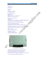
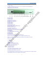
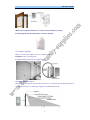
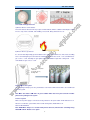
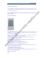
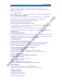
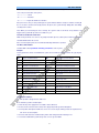
GSM ALARM SYSTEM
USER MANUAL
1. Instruction
The alarm system is based on GSM network. With a GSM SIM card, it can be used wherever you want and
no need to connect any wire, which is convenient and easy to install and use.
Main functions,
English language SMS and voice reminder, Spanish/Chinese/Russian for optional
With Partial arm function
With 2 wired zones, 12 wireless zones
With 3 Relay output to control your home appliances
With voice reminder when users operate the system
Work with external Microphone
Work with external speaker
Auto send SMS to remind users when GSM signal becomes weak
Work with wired & wireless PIR, door/window sensor, smoke/gas detector, glass break sensor etc.
Each wireless zone can match countless wireless sensors.
Users pre-record voice in the system and play the voice when system gives alarm
Send SMS to 3 mobile phones and auto-dial 3 phones to inform the users
Users use any phone to listen what is happening inside the house whenever & wherever.
Program and control the system by keyboard, remotes, SMS or phone remotely.
Send SMS to inform users which zone is alarming and will call users or the police after system is triggered
Use SMS to change the zone name & content
Use SMS to inquiry the system status wherever
With password protection, System will inform users when input wrong password for 3 times
Use any phone to call the system and anyone inside the house -can talk to you through a speaker.
Wireless Emergency function (24 hours zone)
With Backup rechargeable battery, system can work even when the power is failure or cut by intruder.
Send SMS to inform you when the power is failure or returns to normal.
Support monitoring center through GSM network to the police station or management centre
Packing List:
Main panel
Magnetic Door Sensor
Two Wireless Remote Controls
Wireless Programming Keypad
PIR Motion Sensor
Mini Siren
12vDC Power Supply
User Manual
Optional wired & wireless accessories
Door/window magnetic contact
Magnetic steel scrolling door sensor
PIR motion sensor
Curtain PIR sensor
Ceiling PIR sensor
Vibration sensor
2
Smoke sensor
Gas sensor
Glass break sensor
Remote control
Panic button
Speaker
External high sensitivity MIC
Infrared Beam detector
Infrared Fence detector etc
Optional sirens
Wired & wireless indoor siren & strobe siren
Wired & wireless outdoor strobe siren
Wireless solar powered siren etc.
Specification
a) GSM network frequency Standard: 900/1800MHZ, 850/1900MHZ optional
b) External power failure alarm: Start-time: less than 1s
c) Alarm response time Less than 10s (GSM in normality)
d) Power requirements: AC 220V 50Hz
Standby lithium battery: DC8.4V, 700/800mA, 4000mA optional
Standby battery working hours: more than 10 hours, 4000mA for over 3 days
e) Working conditions Operating temperature: -20 to 60
Humidity: 20% to 95%
Wireless frequency 315/433MHZ
2. Main panel description
2.1 Main panel LED description
Z1-Z3: Power indicator. External power off/failure, Z1-Z3 will be off
Z4: Arm LED indicator. After system armed, it will always be on
Z5: Alarm LED indicator. When there is an alarm, it will be on
Z6-Z7: Run LED indicator. LED blinks when GSM network in good condition
Z8:
Relay output 1, Relay activated and LED light is on
3
Z9:
Relay output 2
Z10: Relay output 3
Z11: Wireless LED indicator. When wireless sensors send signal to system, this LED will be on
2.2 Main panel connector and socket
A1: Power switch
A2: DC12V plug in
A3: Wired sensor connector 1
A4: Wired sensor connector 2
A5: Relay output 1
A6: Relay output 2
A7: Relay output 3 (-,
+)
A8: External microphone connector (-,
+)
A9: Siren connector (-,
+)
A10: Speaker connector (-, +)
A11: Connector for future function (Can’t use it now)
A12: SET button
A13: RECORD button for voice record
A14: SIM card slot
A15: GSM antenna
Note: A3 & A4 connector are used to connect wired sensors.
Connect a resistor provide by us to the positive and negative part inside the sensor.
With this resistor, it will alarm immediately when the intruders cut the wire/make short circuit.
It will be much safer.
3
Installation
3.1 Install main unit
a) Insert a valid SIM card into main unit
Note: Make sure the SIM card has money.
b) Install the GSM external antenna
c) Fix and hide main unit
3.2 Install accessories
3.2.1 Install the door/window magnetic contactThe principle of door/window contact sensor
The door/window magnetic contact includes two parts. The sensor will send the wireless signal to the alarm
Panel immediately when the two parts depart more than 15-30mm.
4
The picture of the installation is as follows,
Wired or wireless glass break detector can also be used for window (see below)
It will be triggered when the window glass is moved or vibrated,
The sensitivity is adjustable
Wireless scroll steel door magnetic sensor for scrolling steel door,
Installation: Please see below picture
It is triggered when the two parts are separated to 3cm - 5cm.
3.2.2 Install PIR motion sensor
PIR refers to passive Infra-red. A Passive Infra-red Sensor is an electronic device that detects the motion or
movement of some person or animal by sensing the heat emitted from the body.
5
3.2.3 The installation of wireless ceiling PIR sensor
3.2.4 Install smoke/gas detectors
a) Wired or wireless smoke detector
This smoke detector detects smoke by a couple of infrared diodes, which is suitable for detecting the smoke
in house, shop, hotel, restaurant, office building, school, bank, library and storehouse etc.
b) Wired or wireless gas detector
It is used for detecting leaking gas and suitable for the safety of residential house, villas, hotels, boarding
house etc. Detecting the gas heavier than air: installation height from floor: 0.3m ~ 1.0m, semi-diameter to
gas sources: <1.5m; detecting the gas lighter than air: installation height from ceiling 0.3m ~ 1.0m,
semi-diameter to gas sources: <1.5m.
Open or close manipulator
/Test button
Power LED (green)
Working LED
4 Put a SIM into the system
Use something small tip to press the yellow button, near A14, the SIM card slot will be out. Put SIM card
inside the system.
Note: Make sure that the SIM card is in good condition which has money and can work in mobile
phone before putting it in the system
5 Turn on system
Make sure the power supply is connected correctly, and turn on the power switch. Z1-Z5 indicators are on.
About 15 seconds later, system will be in the normal running status, Z4,Z5 LED are off.
Z6 & Z7 LED will twinkle.
Note: RUN LED is always on or off after main panel is turned on, which means something wrong
with GSM network. Restart it once again.
6
6. Operation steps
6.1 Record alarm voice message
Use something tip to press “REC” button, the system will make a beep sound, then it begins to 6 seconds
record. There are two beep sounds after finishing the record. Users can hear pre-record voice if the speaker
is connected after finishing record.
Note: Voice Message should be brief. For example: “Illegal intrusion, Help, Room 101, Block 12,
16th street, New York”
6.2 Set by wireless keyboard
Close all the wireless detectors. Press “set” button, it will make a beep sound, at the same time the Z5
ALARM LED is on which means the system is in setting status. About 20 seconds, it will give a long beep
and exit setting status automatically.
Note: When setting phone number by keyboard, every time you press the button you can hear a beep
sound for confirmation. If there are no beeps, press the button again.
Press the button “*” before pressing the button “#” to cancel the numbers you have already input.
6.2.1 Set mobile phone numbers to receive SMS.
a. Click SET button, after you hear a beep, it is in setting status, operate the keyboard as below
Input: Serial number + mobile phone number + #
Example: set 13688888888 as the first SMS alarm phone number.
Input 113688888888#, then you will hear two beep sounds for confirmation.
Repeat the same way to set the other two mobile phone numbers.
Note: serial number can only be 1,2,3 and the number “1” is the first SMS alarm phone number,”2” for the
second and “3” for the third mobile phone number.
6.2.2 Delete SMS alarm mobile phone numbers
Input: serial number + #, then can cancel the phone numbers.
Example: The telephone number 13688888888 is the first SMS alarm telephone number. Press the “set”
button then release it, the system will beep.
To delete it, enter the digits: 1#.
Note:
7
1. There are two SMS message that will be sent to the first mobile phone. It informs you whether all of the
contents of the setting are right or not.
The SMS includes, ID, SMS receiving number, alarm call receiving number, passwords.
2. After you press any button on the Keypad, the Control Unit will make a “Beep” sound. If you do not hear a
“Beep”, try again.
3. The alarm light (on the front) is on while these settings are being programmed. The alarm light will be off
after programming is finished.
4. After programming alarm telephone numbers is finished, the system will give a long” Beep to confirm.
6.2.3 Set phone numbers to receive alarm call
When system is triggered, it will call 3 phone numbers that pre-programmed in. Follow the below steps to
set alarm receiving phone number.
Click SET button, after you hear a beep, it is in setting status, operate the keyboard as follows,
Input: Serial number + phone number + #
Example: set 13966666666 as the first phone number for call alarm.
Input 413966666666#, then you will hear 2 beep sounds for confirmation.
Repeat the process to set the other two phone numbers.
Note: serial number can only be 4, 5, 6 and the number “4” is the first phone number for call alarm, ”5” for
the second and “6” for the third mobile phone number.
6.2.4 Delete phone numbers for alarm call
Input: serial number + #, then can cancel the phone numbers.
Example: The telephone number 13966666666 is the first CALL alarm telephone number.
Click the “set” button then release it, the system will beep and it is in setting status
To delete it, press the digits: 4#.
Note:
1. There are two SMS message that will be sent to the first mobile phone. It informs you whether all of the
contents of the setting are right or not.
2. After you press any button on the Keypad, the Control Unit will make a “Beep” sound. If you do not hear a
“Beep”, try again.
3. The alarm light (on the front) is on while these settings are being programmed. The alarm light will be off
after programming is finished.
4. After programming alarm telephone numbers is finished, the system will give a long” Beep to confirm.
6.2.5 Change the password
The factory default password is 1234. The password must be four digits.
Click the SET button then release, after a beep sound, then the system is in setting status
Format: 7 new password #.
Example: to change password to new one 8888:
Press: 78888#
Note:
a. Any button you pressed on the Keypad, the system will beep. If you do not hear a Beep, try again.
b. You can double check the password by calling the system. Only with verified password can you possible
to program the system.
c. Keep a record of the password in a safe location. If you press the password for 3 times, it will give alarm.
6.2.6 Set new ID of the main unit
The ID number is the identification number of each alarm. If there are many alarms, users can easily
recognize which alarm is triggered according to the ID number in the SMS content.
8
The factory default ID is 000000. The serial number must be six digits.
Click the “set” button then release it, the system will beep and it is in setting status
Then input 0 + six digits of new ID + #, the system will make a two beep sounds to confirm the input.
Example: set 123456 as new ID
Input: 0123456 #.
Note: Any button you pressed on the Keypad, the system will beep. If you do not hear a Beep, try again.
6.2.7 Set sending “arm/disarm” SMS or not
When operate the alarm panel by remote controller, users mobile phone can receive “arm/disarm” SMS
Click the SET button then release, after a beep sound, then the system is in setting status
Input “9 # ” on wireless keyboard, then two beep sound for confirmation.
Repeat the above operation way to cancel this function.
6.2.8 Choose open/closed alarm of hardwire zone contact
The factory default mode: when the hardwire zone contact is Normally Open, the system will alarm. If you
want to change it, please follow us the step as below.
Click the SET button then release, after a beep sound, the system is in setting status
Input “8 #”on the keyboard, two beep sound for confirmation. System will alarm when the hardwire contact
is Normally closed.
6.2.9 Exit setting status of the host
System will exit the setting status automatically. Do not press the keyboard if the setting has been done. The
Z5 Alarm LED on the panel will be off 20 seconds later, hear a long beep for confirmation. And it will send the
setting SMS message to first mobile phone pre-programmed in the system.
7. Set by SMS command
7.1 Set three SMS alarm mobile phone numbers
Edit SMS in the mobile phone: 4 digits password + DD + serial number + SMS alarm phone number
Example: Default password is 1234, set 13888888888 as the first SMS alarm phone number.
Send SMS: 1234DD113888888888 to the SIM card phone number in system
Note: The serial number shows alarm sequence (must be 1, 2, 3)
7.2 Set three call alarm phone numbers
Input SMS: 4 digits password + DD + serial number + call alarm phone number
Example: Default password is 1234, set 01088888888 as the first call alarm phone number.
Send SMS: 1234DD401088888888
Note: The serial number shows alarm sequence (must be 4, 5, 6)
7.3 Delete alarm phone numbers
Input SMS: 4 digits password + DD + serial number
Example: Default password is 1234
Send SMS: 1234DD1 to delete the first phone number
Note: The serial number shows alarm sequence (must be 1, 2, 3, 4, 5, 6)
7.4 Change password
Input SMS: 4 digits password + DD + 7 + the 4 digits new password
Example: Default password is 1234, If you want to set 6666 as the new password
Send SMS: 1234DD76666
7.5 Arm/Disarm command
Arm by SMS: 4 digits password + A1
Disarm by SMS: 4 digits password + A2
Example: Default password is 1234,
9
If you want to set the host in arm mode, Send SMS: 1234A1
7.6 Change Zone name
Factory default zone name is zone01, zone02, and so on.
Input SMS: 4 digits password + DM + zone’s code (2 digits) +new name
Send SMS with new name to user mobile phone for confirmation
Example: Default password is 1234, change zone 06’s name into bedroom PIR Alarm.
Send SMS: 1234DM06 bedroom PIR Alarm.
Note: New name should be less than 24 characters. Zone code in 2 digits: 01 to 06
7.7 Inquiry by SMS command
7.7.1 Inquire arm/disarm status
Input SMS: 4 digits password + W1
Send SMS with ARM/DISARM to user mobile phone for confirmation
7.7.2 Inquire external power status
Input SMS: 4 digits password + W2
Send SMS with Power is ok/Power is failure to user mobile phone for confirmation
7.7.3 Inquire relay status
Input SMS: 4 digits password + RR
Send SMS with relay status to user mobile phone for confirmation
7.7.4 Control Relay by SMS
Control Relay 1
Input SMS: 4 digits password + R1 (Relay closed), 4 digits password + R2 (Relay open)
Send SMS with Relay 1 off or on to user mobile phone for confirmation
Control Relay 2
Input SMS: 4 digits password + S1 (Relay closed), 4 digits password + S2 (Relay open)
Send SMS with Relay 2 off or on to user mobile phone for confirmation
Control Relay 3
Input SMS: 4 digits password + T1 (Relay closed), 4 digits password + T2 (Relay open)
Send SMS with Relay 3 off or on to user mobile phone for confirmation
Example: Default password is 1234
Edit SMS in mobile phone 1234R1 and send it to system.
Relay 1 is closed.
7.7.5 Control partial alarm
Input SMS: 4 digits password + zone code.
Send SMS to user mobile phone for confirmation
After the guard zone set as the partial alarm zone, users can’t use remote controller to disarm system
Example: Default passwords 1234, Set zone 03, zone 05, zone 11 as the partial alarm zone
Send 123403,05,11 to system.
7.7.6Cancel partial alarm zone
Input SMS: 4 digits password +AD+ zone code.
Example: Default passwords 1234, cancel zone 03, zone 05 partial alarm zone
Send 1234AD03,05 to system.
Note: Users will receive a SMS about the zone is arm or disarm for confirmation
7.7.7 Other SMS command
Please refer to the SMS command table
8. Set by any phone
10
With correct password, users can use any telephone/mobile phone to call the phone number in the system
and set. It will get connected within 15 seconds and remind users to” Enter password” with voice. Users
should input the password after hear one beep.
After password verified, another beep will sound, and users can remotely listen. Press “*” and after hear two
beeps, system is in setting Status. Follow the below step to set.
Set relay, siren
After hear “Enter command”, press 5 to activate relay 1, press 6 to deactivate relay 1.
Press 7 to activate relay 2, press 8 to deactivate relay 2.
Press 9 to activate relay 3, press 0 to deactivate relay 3.
Press 3 to activate siren, press 4 to deactivate siren.
Note:
1. Every time when you press the phone keyboard, the host will make a beep sound. If not, press it again.
2. Before press “#”, you can press “*” to cancel the numbers which you have already inputted.
3. Input wrong password for 3 times, it will send SMS to users
(1). Set mobile phone numbers for SMS alarm
(2). Set mobile phone/telephone numbers to receive alarm call
(3). Change password
(4). Set new ID
(5). Set whether send “arm/disarm” SMS or not
(6). Choose NO/NC of hardwire zone contact
(7). Exit setting status
The setting ways by phone are the same with wireless keyboard.
9. Usage
9.1 Arm/disarmed by remote controller
a. Press the button “
” on the remote controller, the main panel makes one beep sound and Z4 ARM LED
is twinkling. 30 seconds later, it enters into arm mode and the Z4 ARM LED is still on.
When the Z4 ARM LED is twinkling, you can press the button “
b. Press the button “
” to enter into arm status quickly.
” can disarm, the host make two beep sound, and LOCAL LED and REMOTE LED
are off.
Note: You can see the Z11 wireless LED will be on when you press any button of the remote. It will also be
on when the sensors are triggered.
9.2 Emergency alarm
When an emergency alarm occurs, press the button “
” and the siren goes on intermittently for 90 seconds
to inform the neighbors. At the same time, the system will automatically dial the pre-programmed phone
numbers and send the SMS of “Emergency alarm”.
Note: If nobody answer the phone, it will auto dial each phone number one by one for three times
9.3 External power failure alarm
When the system checks out that there’s something wrong with the external power or the external power is
off for more than 2 seconds, it will enter into alarm status immediately. At the same time, the system will
automatically dial the pre-programmed phone numbers and send the SMS of
“External power failed”.
When the power supply is on, the system will stop alarming immediately and send the SMS of “External
power OK”.
9.4 Alarm and Handling
When an alarm occurs, the siren will alarm for 90 seconds to inform the neighbors. At the same time, the
system will automatically send SMS to report the guarding zones and dial the pre-programmed phone
11
numbers. When the phone call is answered, users can hear the voice message inside the house.
Users can press the button on the phone,
“1”------------------- armed
“2”------------------- disarmed
“3”-------------------inquire the alarm zone numbers
If the phone line is busy or can’t put through, the system will auto-dial the next phone number circularly till
the one of them is answered. If nobody answers the phone, the system will stop dialing after auto-dialing
circularly for three times.
Note: When you are listening the voice remotely, the system is still on arm mode. If any detectors are
triggered, the system will report the zone numbers to you.
9.5 Remote arm/disarm and monitor
With correct password, users can use any telephone/mobile phone to call the phone number in the system
and arm/disarm/monitor the sound.
If the user hand up the phone, the host will automatically terminate the operation.
10. SMS command table
Send the SMS content password+ following command to control system
Example:
Factory password is 1234, send 1234CS2 to system, the siren will not make sound when the system gives
alarm.
CD1
Relay 3 start DVR activated
CM1
Siren with beep sound activated
CD2
Relay 3 stop start DVR deactivated
CM2
Siren without beep deactivated
CS1
Siren with sound when alarm
CG1
GSM signal reminding activated
CS2
Siren with sound deactivated
CG2
GSM signal reminding deactivated
CP1
Power failure alarm activated
CF1
GSM network problem alarm activated
CP2
Power failure alarm deactivated
CF2
GSM network problem alarm deactivated
W1
Inquiry Arm/Disarm status
A1
Arm system
W2
Inquire external power status
A2
Disarm system
DD
Set/delete phone number
RR
Inquire relay status
AD/AA
Inquiry each zone Arm/Disarm
AD+ zone code
Set partial alarm zone
R1
Make Relay 1 contact Closed
S1
Make Relay 2 contact Closed
R2
Make Relay 1 contact Open
S3
Make Relay 2 contact Open
T1
Make Relay 3 contact Closed
DM
Change zone name
T2
Make Relay 3 contact Open
11. Operation Cautions
11.1 This product is designed for the indoor use
11.2 Install the system in a hidden place.
11.3 Turn off the power supply before insert/take out the SIM card.
11.4 Have a hard connection to the main power supply and provide good heat dissipation.
11.5 Don’t put the main panel and wireless sensors close to the objects which generate strong interference,
such as TV set and computer.
11.6 Check all the detectors and their battery in time and change them when battery is low.
11.7 Check the GSM alarm system termly, make sure it is good condition
12
12. Wireless detector and Remote controller encode
13
D0
D1
D2
D3
(13)
(12)
(11)
(10)
NC
NC
NC
NC
NC
NC
NC
NC
Zone 01
0
0
1
0
Zone 02
1
0
1
0
Wireless
Zone 03
0
1
1
0
IR sensor,
Zone 04
1
1
1
0
Magnetic
Zone 05
1
0
0
1
Zone 06
0
1
0
1
Zone 07
1
1
0
1
Zone 08
0
0
1
1
Zone 09
1
0
1
1
Zone 10
0
1
1
1
Zone 11
1
1
1
1
1
1
0
0
Wireless address code (A0 to A7)
Name
There is a label with wireless address code
Main unit
on the back of alarm.
Wireless Keypad
contact,
Beam detector
Smoke detector
Gas detector
etc
Fire zone
Remark: “1”---------- connect H and N
“2”----------NO connect
“0”----------connect L and N
“NC”-------NO request
Zone 1 is also the emergency alarm zone
14