1
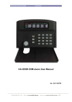
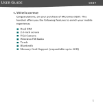
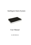
G12E & G12EA
GSM ALARM SYSTEM
USER MANUAL
Ver 0811 2009-12-15
Contents
1. Instruction--------------------------------------------------------------------------------------- 1
2. Installation---------------------------------------------------------------------------------------1
2.1 Insert a valid SIM in to the host--------------------------------------------------------------------------1
2.2 Install the detectors/sensors-----------------------------------------------------------------------------1
2.3 Run------------------------------------------------------------------------------------------------------3
3.Set the host by SMS ---------------------------------------------------------------------------------3
3.1 Set mobile phone number for SMS----------------------------------------------------------------------3
3.2 Set phone number for auto-calling----------------------------------------------------------------------3
3.3 delete phone number for SMS and auto-calling-------------------------------------------------------3
3.4 Change the password of the host ------------------------------------------------------------------------4
3.4 Arm/Disarm command ------------------------------------------------------------------------------------4
3.5 Change Zone’s name --------------------------------------------------------------------------------------4
3.6 Inquire host’s arm/disarm status--------------------------------------------------------------------------4
3.7 Inquire host’s external power status----------------------------------------------------------------------4
4. Usage-------------------------------------------------------------------------------------------- 4
3.1 Arm/disarm by remote controller--------------------------------------------------------------5
3.2 Emergency alarm------------------------------------------------------------------------------------- 5
3.3 External power failure alarm---------------------------------------------------------------------------5
3.4 Alarm and Handling-------------------------------------------------------------------------------------5
3.4 Remote arm/disarm/monitor----------------------------------------------------------------------------5
Operation Cautions------------------------------------------------------------------------------------------5
Dear users,
Thank you for purchasing our products. Please read through this manual before using this product
so as to operate the product properly.
The GSM alarm system adopts the newest GSM network and Digital Signal Processing
technology, and is widely used in security field. With SMS data transmission and voice platform
of GSM network, it really realizes wireless alarm control and remote managements and solves the
limitation of wired data transmission in telephone and wired network.
Perfect structure, convenient installation, easy operation with wireless control keyboard are
designed for the idea of people-oriented, which will make you feel easy and comfortable while use
this system.
“People is center, technology is first” is our company’s action rule. Customer Satisfaction is our
consistent pursuit. Perfect system, excellent services, sincere attitudes will bring you a new
enjoyment.
1. Instruction
The alarm system adopts SMS data transmission and voice platform of GSM network to send
control command and receive alarm remotely. The system can be set delayed-arm. When a signal
is detected by detectors, the detectors will send alarm signal to host immediately, then the host
sends alarm SMS to its pre-set mobile phone numbers, and meanwhile dials its pre-set
telephone/mobile phone numbers automatically and drive wiretap. In addition, users can dial the
system and set it in arm/disarm mode by any remote phones.
Following are the specific functions:
1.GSM alarm transmission, without connecting telephone lines and be not afraid of
cutting line.
2.The host automatically stores system status, while its power is off.
3. The system equips backup rechargeable battery .It can work while the external power
is off.
4.When a signal is detected by detectors, the detectors will send alarm signal to host immediately,
then the host sends alarm SMS to its pre-set phone numbers, and meanwhile dials its pre-set
mobile phone numbers automatically and drive wiretap.
5.Remote arm/disarm, and set the host by telephone
6.You can increase/decrease detectors
7.Support remote arm/disarm by telephone
8.Can connect with the alarm center through GSM network..
9.Specification:
Work voltage: 9V-12VDC Idle Power Consumption: 0.6W
2.installation
2.1Insert a valid SIM into the host
Use something with a small tip to press the yellow button on the upside of the main panel,the SIM
card slot will come out..put the SIM card inside the system carefully.
2.2 Install the detectors/sensors
2.2.1 Install the door/window magnetic contact
The principle of door/window contact sensor
The door/window magnetic contact includes two parts, and the two parts must be installed very
closely, not more than 15mm. Any time the two parts depart more than 15mm, the sensor will
send the wireless signal to the alarm host immediately. Please make sure the installation distance
and stick them fastness.
The picture of the installation is as follows,
2.2.2 Install the wireless PIR motion sensor
The principle of PIR motion sensor
The principle of the PIR based on the body infrared ray. A Passive Infra-red Sensor is an
electronic device that detects the motion or movement of some person or animal by sensing the
heat emitted from the body. It sets off an alarm automatically at the approach of these warm
beings to within a certain specific radius within its view. The 'passive' in the Passive Infra-red
sensor means that the device does not emit the infra-red rays. It merely detects the emission from
another source. All objects emit a black body radiation which is not seen by our eye but can be
detected by electronic devices like the PIR sensor.
The installation picture of PIR motion sensors
The installation picture of 360° Passive Infrared Sensor.
2.2.3 Install the siren, DVR and wired sensor
Connect the siren, DVR or other electronic appliance to the main unit and fix them in appropriate
place. Please see 2.3 DB-9 connections.
* Connect pin 3 to pin 4, pin 1 to pin 2 to install wired sensors.
* Connect pin 6 to pin 7 to install the DVR/other electronic appliances.
2.3 Run
When the power supply is connected correctly, the LED light of POWER indicator is yellow.
When you turn on the back of host ON switch, LED light of POWER indicator changes to orange.
in the meantime,the LED light of ARM and ALARM indicator keep on. then the host enters the
status of initialization and searches GSM network about 25 seconds later, the host enters into the
normal running status. in the meantime, the ARM light return to normal status, and the light of
ALARM indicator turns off.
Note: During the host’s running, if it makes “di,di,di,di” sounds or the RUN LED is on or off
all the time, this means something wrong with GSM!
3.Set the host by SMS
3.1 Set mobile phone numbers for SMS.
The format of SMS is: Password +DD+ Serial number+ mobile phone number.
Note: serial number represents the order of receiving alarm (can only be 1,2,3).
Example: set 13688888888 as the first SMS alarm phone number, the password of host is 1234,
Then the content of SMS is : 1234DD113888888888.
Repeat the process to set the other two mobile phone numbers.
Note: We suggest that you set the first SMS alarm mobile phone number because if you do
not set the first one, you will be unable to know whether all of the contents of the setting is
right or not.
3.2 Set phone numbers for auto-call.
The format of SMS is: Password +DD+ Serial number+ mobile phone number.
Note: serial number represents the order of receiving alarm (can only be 4.5.6).
Example: set 01088888888 as the first SMS alarm phone number, the password of host is 1234,
Then the content of SMS is : 1234DD401088888888.
3.3 Delete alarm phone numbers for SMS and call
The format of SMS is: four digits Password +DD+ Serial number
Note: serial number represents the order of alarm (can only be 1,2,3.4.5.6).
Example: Delete the first alarm number, the password of host is 1234,
Then the content of SMS is : 1234DD1
3.4 Change the password of the host
The format of SMS is: four digits Password +DD+ 7+four digits new password
Example: set 5678 as new password
The content of SMS is:1234DD75678
3.5 Arm/Disarm command
If you want remote arm by SMS, then the format of SMS is: four digits password+A1
If you want remote disarm by SMS, then the format of SMS is: four digits password+A2
Example: The password of host is 1234,if you want to remote arm by SMS,
Then the content of SMS is: 1234A1
3.6 Change Zone’s name
The format of SMS is: four digits password + DM+ zone’s code (2 digits)+ Changed zone name
Return SMS: Changed zone’s name.
Note: Changed name should be less than 24 characters.
Zone’s code in 2 digits: 01 to 06
Example: The password of host is 1234, If you want to change zone 06’s name into bedroom PIR
Alarm. Then the content of SMS is: 1234DM06 bedroom PIR Alarm
3.7 Inquire host’s arm/disarm status
The format of SMS is: four digits password + W1
Return SMS: The host’s arm/disarm status
3.8 Inquire host’s external power status.
The format of SMS is: four digits password + W2
4. Usage
4.1 Arm/disarmed by remote controller
a. Press the button “ ” on the remote controller, the host makes “di” sound and the light of ARM
is twinkling. 30 seconds later the host enters into arm mode and the light of ARM are on.
When the light of ARM indicator is twinkling, you can press the button “ ” to enter into arm
status quickly.
b. Press the button “
is off.
” can disarm, the host make “di,di” sound, and the light of ARM indicator
4.2 Emergency alarm
When an emergency alarm occurs, press the button “ ” and the siren goes on intermittently for 90
seconds to inform the neighbors. At the same time, the system will automatically dial the pre-set
phone numbers cycled for three times and send the SMS of “Emergency alarm”.
4.3 External power failure alarm
When the system checks out that there’s something wrong with the external power or the external
power is off for more than 2 seconds, it will enter into alarm status immediately. At the same time,
the system will automatically dial the pre-seted phone numbers cycled for three times and send the
SMS of “External power failed”.
When the power supply is on, the system will stop alarming immediately and send the SMS of
“External power OK”.
4.5 Alarm and Handling
When an alarm occurs, the siren will alarm for 90 seconds to inform the neighbors. At the same
time, the system will automatically send SMS to report the guarding zones and dial the pre-set
phone numbers. When any phone is answered, you can hear the voice message and monitor the
sound at site. If the phone line is busy or can’t put through, the system will auto-dial the next
phone number circularly till the one of them is answered. If nobody answers the phone, the
system will stop dialing after auto-dialing circularly for three times.
Note: If there are external speakers, you can achieve two-way communication after you answer
the phone.
5. Operation Cautions
1.Make sure the equipments have no water.
2. Install the system in a hidden place.
3. Turn off the power supply before insert/take out the SIM card.
4.Have a hard connection to the main power supply and provide good heat dissipation.
5. Check all the detectors and their battery in time and change them when power is low.
6.This product is designed for the indoor use rather than outdoor use.
7. Don’t install the system close to the objects which generate strong interference, such as TV
set and computer.
How to program wireless sensors to work with GSM alarm main panel?
Take PIR motion sensor for example. Open the case of PIR, you can see below picture,
Make A0-A7 the same with GSM alarm panel, D0-D3 is the zone code, please find the zone code
of every zone in below table C
Example, on the back of GSM alarm, there is a label written Wireless add 10120120
The A0-A7 of PIR also should be 10120120
If you want to make it work in zone 1, D0-D3 should be 1010
Make it work in zone 2, D0-D3 should be 0110
Table C
D0
D1
D2
D3
(13)
(12)
(11)
(10)
NC
NC
NC
NC
NC
NC
NC
NC
Zone 01
0
1
0
1
Zone 02
1
1
0
1
Wireless
Zone 03
0
0
1
1
sensors
Zone 04
1
0
1
1
Zone 05
0
1
1
1
Zone 06
1
1
1
1
Fire zone
1
0
0
1
Gas zone
1
0
0
1
Emergency zone
0
0
1
0
TABLE C
Wireless address code (A0 to A7)
There is a label with wireless address code
Main unit
on the back of alarm, see below example
Wireless Keypad
Remark: “1”---------- connect H and N
“0”----------connect L and N
“2”----------NO need to connect “NC”-------NO need to connect