1
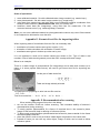
Digital Photogrammetric System Version 6.0 USER MANUAL ScanCorrect Content INTRODUCTION 3 DESCRIPTION OF PHOTOMOD SCANCORRECT 3 Creating disturbances fields 5 Viewing disturbances fields 6 Viewing field’s statistics 7 Creating tables with crosses values 7 Viewing tables 8 Viewing files with raster image 8 Transforming images 9 Converting images format 9 Working in batch mode 10 APPENDIX A. TERMS 11 APPENDIX B. LIST OF WINDOWS 11 APPENDIX C. MESSAGES 12 APPENDIX D. EXAMPLES 13 APPENDIX E. FORMAT OF TEXT FILES FOR IMPORTING TABLES 15 APPENDIX F. RECOMMENDATION FOR SCANNING 15 ScanCorrect INTRODUCTION PHOTOMOD ScanCorrect module is designed for compensation of metric errors occurred when scanning graphical data on flatbed polygraphic scanners. Transformation of raster data considering scanner‟s disturbances field is used for errors compensation. Scanner‟s disturbances field is created using raster data obtained by scanning calibrated material (regular grid or regular set of crosses). The technique for working with PHOTOMOD ScanCorrect consists of the following: include calibrated material into sequence of scanning of graphic material (for obtaining disturbances field); create scanner‟s disturbances field using raster data from the scanning of calibrated material; transform raster data using disturbances field. Research on the metric properties of flatbed scanners shows that disturbances field is mostly due to systematic scanner errors. This permits the use of disturbances field created from one image to transform another. If the original material (e.g. photomaterial) has calibrated crosses on it, the technique remains the same with the only difference that disturbances field is created using the same raster data that is used in transformation. It is possible also to input and use the table containing coordinates of crosses. Input and output data of the program are 1, 4, 8 and 24-bit Windows .bmp files or TIFF. Auxiliary data (disturbances fields) is stored in .etm files. Graphic interface of PHOTOMOD ScanCorrect is based on graphic MS Windows shell. You can operate the program using hierarchic pull-down menu. Basic functions are also realized in the toolbar. PHOTOMOD ScanCorrect works under Windows NT, Windows„98 and Windows 2000 with Win32s. DESCRIPTION OF PHOTOMOD ScanCorrect To launch the program choose START | PHOTOMOD | PHOTOMOD ScanCorrect Main menu bar contains the following 6 menus: Fields Tables Images Batch mode Help Exit Basic operations are realized in toolbar: - Creation of disturbances field - View and edit disturbances field - Statistics on disturbances field 3 RACURS Co., Ul. Yaroslavskaya, 13-A, office 15, 129366, Moscow, Russia PHOTOMOD 6.0 - Creation of table - View and edit table - View image file - Image transformation It is necessary to transform scanned image to compensate scanner errors. Information on distribution of scanner errors required for transformation is stored in files with .etm extension. This information is created during the construction of disturbances field. You can consider table values of crosses coordinates for transformation. Chart of data flows in the program Original files with raster images of photomaterial and calibation material in *.bmp format and tables containing coordinates of crosses in ASCII format PH OTOM OD ScanCorrect *.bmp files with corrected data *.etm files with disturbances fields, *.sct files with tables Tasks you can solve with the program - get metrically correct data on the basis of: 1. scanned raster images of original photomaterial and calibrated material; 2. scanned raster image of original photomaterial with calibrated crosses on it; 3. scanned raster image of original photomaterial with calibrated crosses on it taking into account table with coordinates of crosses; 4. scanned raster images of original photomaterial with crosses and calibrated material taking into account table with coordinates of crosses on photomaterial; 5. scanned raster images of original photomaterial and calibrated material taking into account table with coordinates of crosses on calibrated material. Order of operations depends upon the task being solved: 1. compensation of scanner‟s systematic errors create scanner‟s disturbances field in the scanned area using calibrated material (Field|Create), transform the raster image of photomaterial using this disturbances field (Images|Transform). 2. improvement of metric characteristics of a raster image using calibrated crosses if they have regular coordinates with sufficient precision create scanner‟s disturbances field in scanned area using the raster image of photomaterial (Field|Create), transform the raster image of photomaterial using this disturbances field (Images|Transform). 3. improvement of metric characteristics of a raster image using calibrated crosses with known coordinates © 2013 4 ScanCorrect input table of crosses‟ coordinates. The table can be imported from an ASCII file or entered manually (Table|Create), create scanner‟s disturbances field in the scanned area using raster image of photomaterial taking into account table with coordinates (Field|Create), transform raster image of photomaterial using this disturbances field (Images|Transform). 4. The task can be solved as a combination of tasks described in 1 and 3 5. compensation of the systematic scanner error using non-ideal calibrated material with known coordinates of crosses create scanner‟s disturbances field in the scanned area using raster image of the calibrated material taking into account table with coordinates (Field|Create), transform raster image of photomaterial using this disturbances field (Images|Transform). Note: You can use disturbances field of non-ideal calibrated material obtained on metric scanner as a table for its crosses coordinates. To do this choose ”import from .etm” when creating table. There is a possibility to view and edit the scanner‟s disturbances field and calculate its statistics. Disturbances field, minimized using least squares method, is visualized in such a way that by the color of its points you can judge the absolute error in that point. Efficiency of this technique of metric compensation of systematic scanner‟s error can be checked in the following way: scan metrically correct grid with a small distance between crosses two times shifting it slightly after first scan, create disturbances field using one of them, transform another image using created field, create field using transformed image analyze statistics and compare this field with original. Creating disturbances fields In order to create disturbances field you should: choose Fields|Create field in the main menu or push the button in toolbar. Dialog window Create field will appear. push the Input button in Image part of the dialog. Dialog window Open File will appear. Choose file with raster image of calibrated material. After that window with this image and dialog window controlling input of crosses’ points will appear. To start the automatic search of crosses centers (or nodes of grid) you must select on the image two adjacent (in horizontal direction) well defined crosses (nodes of grid). To do this, place cross-shaped marker on cross‟s center and push the button Cross 1 in controlling dialog window, then place marker on an adjacent cross and push the button Cross 2. Instead of using buttons in controlling dialog window you can simply press <1> and <2> keys on a keyboard. You can also use arrow keys on keyboard for marker positioning instead of a mouse. 5 RACURS Co., Ul. Yaroslavskaya, 13-A, office 15, 129366, Moscow, Russia PHOTOMOD 6.0 To transform an image using disturbances field, you need to link image coordinate system and field coordinate system. You need establish this connection in case of working with disturbances field created from a calibrated material. If crosses were on original image, there is only one coordinate system and you do not need to create the link between different systems explicitly. It is done automatically using the beginning of raster image (point with (0, 0) coordinates). To create reference between disturbances field and scanner‟s working field you should select a reference point position of which does not change in the scanner‟s plane from one scanning to another. For selecting place cross-shaped marker on required image point and press button Reference in controlling dialog window. Instead of using buttons in controlling dialog window you can simply press <3> on a keyboard. You can also use arrow keys on the keyboard for marker positioning instead of the mouse. If you need to take into account crosses table values you should push Input button in the Table part of the dialog. Dialog window Open File will appear. Choose file with table values. After that window with image and dialog window controlling input of crosses points will appear. To link coordinate system of crosses on raster image and coordinate system of crosses in table you must select on image well defined cross (node of grid). To do this, place cross-shaped marker on cross‟s center and press button Reference in controlling window. Instead of mouse you can use keyboard - arrow keys for positioning and <1> for input. input table‟s row and column of selected cross In the Field part of Field creation window you can edit fields file name. By default disturbances field is saved with file name taken from raster image and extension “*.etm”. To create disturbances field (taking into account table, if any) push Create button in Field part of the dialog. Window indicating progress in determining crosses positions will appear. Automatically determined crosses are shown in green color, failures to find cross are shown in red. After successful completion of automatic search procedure message “N% crosses found“ will appear. Positions of not found crosses calculated by interpolation of adjacent determined crosses. Viewing disturbances fields To view disturbances field you should choose Fields|View field from the main menu or push the button in toolbar. Dialog window Open File will appear. © 2013 6 ScanCorrect Choose file with disturbances field. Files with .etm extension filtered for opening by default. Field view window will appear. It comprises two color plates each representing disturbances along different axes. Moving mouse cursor above them you can see error in the point and point‟s coordinates (in plane coordinate system) in lower part of the window. Crosses on plates represent crosses used for field creation. You can edit manually coordinates of crosses. For example you may need this for correcting crosses that were not found automatically. These crosses are painted in dark color. To edit coordinates you should: select cross by right-clicking somewhere near it or position marker on it by arrow keys and press Enter; If the program fails to found and open file with image you will get message ”Can’t open file”. Otherwise Manual crosses setting window appears. It consists of part of original image around the cross and some buttons. There is cross-shaped marker on image which you can move by right-clicking or by arrow keys. Buttons below image realize the following commands: move to next cross; move to next not-found cross; move to previous cross; move to previous edited cross; set new coordinates of current cross; change scale of image part; scroll window so that cross-shaped marker to be in the window center; exit from manual editing. Viewing field’s statistics When viewing disturbances field (when the window with them is current window in program) you can get some statistic information about the field. Choose Field|Statistics or Table|Statistics from main menu or push the button toolbar. in Dialog window Statistics with two histograms (for two axes) will appear. There are also number of crosses, minimum, maximum (for “+” and “-”) error, average of absolute errors and average square error. All data calculated separately for two axes using the whole field. Creating tables with crosses values To create table with crosses values you should: choose Tables|Create table from main menu or push the button in toolbar. Dialog Input table will appear. Depending upon the source of table data (ASCII file, .etm file, manual input) you should: 7 input table‟s dimensions in Number of crosses part of the dialog (it is required for manual input and import from ASCII). RACURS Co., Ul. Yaroslavskaya, 13-A, office 15, 129366, Moscow, Russia PHOTOMOD 6.0 push one of three buttons depending upon tables data source. For import from ASCII file and .etm file you will be asked for file name. Window with table view will appear. This window looks the same as field view. When filling table with values table view supports some helping operations. You can: 1. choose current cross by right-clicking around it in table view or select it by arrow keys and press <Enter>. Another way to move to particular cross – input it‟s row and column in current cross part of the dialog and push the button Go to; 2. input current cross‟s coordinates. To do this input them in Coordinates part of the dialog (fields “X” and “Y”) and push the button Input (next cross automatically becomes current); 3. refresh table view so that it corresponds to all updates by pushing the button Update. For future work with table you must save it: push the Save button Input in the Save File dialog file name. By default, extension .sct is used for files with tables. Viewing tables To view a table you should: choose Tables|View table from the main menu or push the button in toolbar. Dialog window Open File will appear. Select file with table. Files with *.sct extension filtered for opening by default. Window with table view will appear. This window is complete analog of field view. Crosses on table view schematically represent crosses placement in a table. You can edit its coordinates. They have different colors depending upon its current state: 1. not significant (on the border) - black 2. not entered - blue 3. entered - white To change coordinates you should: select desired cross by right-clicking around it or using arrow keys and press Enter Dialog Input table described in previous section will appear. Viewing files with raster image To view file with raster image you should: choose Image|View from the main menu or push the button © 2013 in toolbar. 8 ScanCorrect Dialog window Open File will appear. select file with image. After that window with image will appear. You can not change its scale and it is 1:1 (point on raster image / pixel on screen). To scroll image window use <PgUp>, <PgDn>, <Home> and <End> keys and standard window scroll bar. Transforming images To transform an image you should: choose Images|Transform from the main menu or push the button in toolbar. Dialog Transformation will appear. Push the Input button in the Original Image part of the dialog. Dialog window Open File will appear. select file with raster image. After that image view window and window controlling input of points will appear. To transform image using disturbances field you must link image‟s coordinate system and field‟s coordinate system. To create a reference between scanner‟s working area and image area you must select a reference point which position does not change on scanner‟s plane from one scanning to another. For selecting place cross-shaped marker on required image point and press Reference button in controlling dialog window. Instead of using buttons in controlling dialog window you can simply press <1>. You can also use arrow keys on keyboard for marker positioning instead of mouse. in disturbances field part of the dialog push the Input button. Dialog window Open File will appear. select file with disturbances field. in transformed image part of the dialog enter file name for transformed image and push the button Transform. After that progress indicator in the lower part of the dialog will start moving. At any time you can press Cancel. After successful transformation you will get “Success” message. Converting images format To convert an image (*.bmp to *.tif, *.tif to *.bmp) you should: choose Images|Convert from the main menu. Dialog Convert will appear. 9 RACURS Co., Ul. Yaroslavskaya, 13-A, office 15, 129366, Moscow, Russia PHOTOMOD 6.0 Push the Input button in the Original Image part of the dialog. Dialog window Open File will appear. select file with raster image. in convert image part of the dialog enter file name for converted image and push the button Convert. After that progress indicator in the lower part of the dialog will start moving. At any time you can press Cancel. After successful transformation you will get “Success” message. Working in batch mode Batch mode is very useful feature of PHOTOMOD ScanCorrect program since it‟s a very typical situation when you want to transform all images of the big source block by single mouse click. To start processing in batch mode select Batch mode / New project from the main menu. As a result the following dialog opens: The simplest way to transform the source images is to add them to the list by using the Add button, select the corresponding disturbances field file with .etm extension (Disturbances field file) and push the Transformation button. The transformed images will be placed to the directory selected in Transformed images column. You can also save the settings of the batch project to .psp file (Save and Save As buttons) and start it later by using Batch mode / Old project option of the main menu. Use batch mode dialog elements to: Add – add image files to be transformed to the list (you can use standard Windows tools (Shift and Ctrl keys) for group file selection) Delete – delete source image files from the list Save – save project settings (file names and other parameters) to the current special .psp file in order to load it later Save As – save project settings (file names and other parameters) to the .psp file with a new name in order to load it later © 2013 10 ScanCorrect Transformation – start transformation process Close – exit the batch mode dialog Input images – view selected images file names Transformed images – change output transformed image file name by double mouse click and editing Reference point – change the position of the reference point (if any) by double mouse click (see the chapter Creating disturbances field) Directory of transformed images – select transformed images directory Add to transformed images file name – add some characters to the source image file name to form the output image file name (the default is _TR) Disturbances field file – select the file of disturbances field (.etm extension) (see the chapter Creating disturbances field) LOG file – select the name of LOG file used to store the information of the batch processing. Appendix A. Terms disturbances field – a set of data, characterizing scanner‟s metrical errors in some scanned area. It takes into account non-squareness of raster element if calibrated material is regular with enough precision. reference point – a point on raster image, correspondent to some characteristic physical point on static object in scanner‟s working area. You can use a corner of some object, fastened on scanner‟s plane, which remained in its position during scanning sequence. calibrated material – regular grid or regular set of crosses with small period made on nondeforming material like glass or special film. Based on raster image of this object, obtained via scanning, disturbances field is created by the program. Appendix B. List of windows View image Window controlling input of points Create field View field Manual input of cross Statistics Open File and Safe File Window indicating automatic search of crosses Input table Transformation View image is a window with part of image inside it. It has scroll bars and designed for viewing raster image and selecting required points on it. You can use mouse or <PgUp>, <PgDn>, <Home> and <End> keys for scrolling. To select a point on image place crossshaped marker by mouse or keyboard and press required key or button in Window controlling input of points. Window controlling input of points consists of a number of buttons with names of characteristic points (depends upon current action) and the buttons Ok and Cancel. In the upper part of it you can see some description of required actions. Create field is a dialog window with three input fields: Image, Table and Disturbances field. It is used to form a task of building disturbances field. Near the fields Image and Table there is the button Input and edit fields to enter the name of a file. To form a task of building 11 RACURS Co., Ul. Yaroslavskaya, 13-A, office 15, 129366, Moscow, Russia PHOTOMOD 6.0 disturbances filed the user must point two crosses and possibly a reference point, that is why the user cannot input image file name manually, and all appropriate window elements are blocked. After the name of file is input the user is allowed, if he needs, to input the table of crosses coordinates. Since the table must be linked to the field, the manual input of table file name is also blocked and the table must be input through the button Input. In the field Field the output file name is formed automatically and it can be edited. View field. It comprises two color plates each representing disturbances along different axes. Small errors represented by shades of green, “+” errors by shades of red and “-” errors by shades of blue. Moving mouse cursor above them you can see error in the point and point‟s coordinates (in plate coordinate system) in lower part of the window. Manual input of cross contains a part of original image with Scroll Bars and some buttons. There is a cross-shaped marker on it that you can move with arrow keys on a keyboard or with right-click of a mouse. To enter new coordinates you can use Change button or <Enter> on a keyboard. The field will be updated automatically. To move between crosses you can use the Next, Next not found, Previous, Previous changed buttons. You can also scale image using 2 and ½. Statistics has two histograms (for two axes). There are also number of crosses, minimum, maximum (for “+” and “-”) error, average of absolute errors and average square error. All data calculated separately for two axes using the whole field. Open File and Save File are standard MS Windows dialogs. Window indicating automatic search of crosses supplies visual feedback when algorithm of finding crosses on raster image is working. Automatically found crosses are painted in green and not found crosses in red. Its positions will be interpolated. Input table is a dialog window divided into three parts: part for defining table‟s parameters, part for entering coordinates and part with controlling buttons. Part for defining parameters has In row and In column fields, that serves for defining table‟s dimensions, and the Import (*.txt), Import (*.etm), Manual input buttons, defining the way of entering coordinates. Part for entering coordinates has two parts: Current cross and Current coordinates. Current cross part has two fields for numbers of current row and column and Go to button. You can enter the numbers of required cross and switch to it by pressing Go to button. Current coordinates part has two fields for coordinates and the Input button. You can edit values in this field and enter them into the table by pressing the Input button. In the part with controlling buttons use the Save button to save the table and the Update button to show the updated picture of the table. Transformation window serves for input of required data for transformation (original file, field file and output file). It also has progress indicator, which shows amount of work already done, and Cancel button. Appendix C. Messages “Success” - Appeared after process of image transformation is successfully completed. “N% of crosses found” - Appeared after automatic search is completed. By this percentage you can judge about efficiency of automatic search. “Not enough disk space”, “Not enough memory” - messages about a shortage of system resources. Free disc space or memory. “Can’t transform image” “Field does not overlap image”. It is required that field you are using should be greater than image. Probably wrong reference point. “Canceled by user”. Response to pressing Cancel or Esc during lengthy operations. © 2013 12 ScanCorrect “Errors when working with file” “Can’t open file” “Can’t read file” “Can’t create file” “Can’t write file” “Wrong field format” - the file you selected is not a file with disturbances field or corrupted. “Can’t create two fields simultaneously” - current program limitation. “Can’t transform two images simultaneously” - current program limitation. “Too little crosses found” - appeared when automatic search fails to find more than certain percentage of crosses. “Can’t find crosses” - automatic search fails to find two adjacent crosses you selected on image, try to select another crosses. “Crosses too near” - automatic search can work only beginning with some minimum distance between crosses. “Not a .bmp file”, “Unsupported bits per pixel in .bmp file” - file with this format can‟t be processed by program. “Unknown error” Appendix D. Examples Task 1. We have calibrated material and photomaterial and we need to compensate systematic metric scanner errors. Note 1. It is required that there should be some fixed (on scanner‟s plane) object on both raster images, or scanned area should be the same in both scans (in scanner‟s coordinate system) (see Appendix F. Recommendations for scanning). Note 2. Calibrated material and photomaterial must be scanned with the same resolution. Order of operations: 1. scan calibrated material - file with calibrated raster image is created (e.g. master.bmp ); 2. scan photomaterial - file with raster image is created (e.g. image.bmp ); 3. using data from master.bmp create scanner‟s disturbances field, save it to master.etm. Do not forget to select reference point - characteristic point correspondent to some fixed point (see. Note 1 above); 4. transform raster data (file image.bmp), using field from file master.etm selecting the same reference point. File with corrected image (e.g. newimage.bmp) is created Note: To control the quality of automatic search use Fields|View field where you can enter coordinates manually. Task 2. We have photomaterial with calibrated crosses on it, we need to compensate systematic metric scanner errors, assuming that crosses on image are regular with enough precision. Note: For typical flatbed scanners errors can be compensated if grid period is no more than 1 sm. Order of operations: 1. scan photomaterial - file with raster image is created (e.g. image.bmp ); 2. using data from image.bmp create scanner‟s disturbances field (this field is the sum of scanner and photomaterial errors), save it to master.etm; 3. transform raster data (file image.bmp), using field from file master.etm selecting the same reference point. File with corrected image (e.g. newimage.bmp) is created 13 RACURS Co., Ul. Yaroslavskaya, 13-A, office 15, 129366, Moscow, Russia PHOTOMOD 6.0 Task 3. We have photomaterial with calibrated crosses on it, we need to compensate systematic metric scanner errors and errors of photomaterial, assuming that correct coordinate of crosses are known. Note. For typical flatbed scanners errors can be compensated if grid period is no more than 1 sm. Order of operations: 1. scan photomaterial - file with raster image is created (e.g. image.bmp ); 2. input manually (or import) table with correct coordinates of crosses, save it to file (e.g. image.sct); 3. using data from image.bmp and table from image.sct create scanner‟s disturbances field (this field is the sum of scanner and photomaterial errors), save it to image.etm; 4. transform raster data (file image.bmp), using field from file master.etm selecting the same reference point. File with corrected image (e.g. newimage.bmp) is created Task 4. We have calibrated material and photomaterial with calibrated crosses on it, we need to compensate systematic metric scanner errors and errors of photomaterial, assuming that correct coordinates of crosses are known. Note 1. This task can arise if we have calibrated material with small grid period and photomaterial with large grid period. For typical flatbed scanners errors can be compensated if grid period is no more than 1 sm. The less the period the better results can be obtained. Note 2. It is required that there should be some fixed (on scanner‟s plane) object on both raster images, or scanned area should be the same in both scans (in scanner‟s coordinate system) (see Appendix F. Recommendations for scanning). Note 3. Calibrated material and photomaterial must be scanned with the same resolution. Order of operations: 1. scan calibrated material - file with calibrated raster image is created (e.g. master.bmp ); 2. scan photomaterial - file with raster image is created (e.g. image.bmp ); 3. using data from master.bmp create scanner‟s disturbances field, save it to master.etm. Do not forget to select reference point - characteristic point correspondent to some fixed point (see. Note 1 above); 4. transform raster data (file image.bmp), using field from file master.etm selecting the same reference point. File with corrected scanner errors (e.g. image_tr.bmp) is created; 5. input manually (or import) table with correct coordinates of crosses, save it to file (e.g. image.sct); 6. using data from file with transformed raster image image_tr.bmp create disturbances field of photomaterial taking into account table image.sct, save field in file image_tr.etm; 7. transform raster data (file image_tr.bmp), using field from file image_tr.etm. File with corrected errors (e.g. newimage.bmp) is created; Task 5. We have non-ideal calibrated material and photomaterial, we need to compensate systematic metric scanner errors, assuming that correct coordinates of crosses on calibrated material are known. Note 1. To obtain correct coordinates of crosses on non-ideal calibrated material: 1. scan calibrated material on photogrammetric scanner. File with raster image (e.g. ideal.bmp) is created; 2. using data from ideal.bmp create disturbances field, save it to ideal.etm; 3. create table with correct coordinates of crosses on calibrated material using import from .etm with file ideal.etm, save table in a file (e.g. ideal.sct); © 2013 14 ScanCorrect Note 2. Calibrated material and photomaterial must be scanned with the same resolution. Order of operations: 1. scan calibrated material - file with calibrated raster image created (e.g. master.bmp ); 2. scan photomaterial - file with raster image created (e.g. image.bmp ); 3. using data from master.bmp and table with correct calibrated material coordinates from ideal.sct create scanner‟s disturbances field, save it to master.etm. 4. transform raster data (file image.bmp), using field from file master.etm. File with corrected scanner errors (e.g. newimage.bmp) is created; Note: you can scan calibrated material on photogrammetric scanner only once if the material is not subjected to deformation over the time. Appendix E. Format of text files for importing tables When importing table of coordinates from text file it is necessary that: coordinates of crosses centers were given in pairs: (X,Y); orientation of table coincides with orientation of raster image; coordinates were given in bottom-up order row by row. It is not important in what unit‟s crosses centers are written in file. Type of data is real numbers. Size of table should guaranty more than 50% overlap with raster image. Below is an example: There is a raster image of photomaterial (file image.bmp) and a table with crosses (on a paper or in some popular table format), we need to get correct text file for importing into system Let the part of table looks like ... ... XA YA XB YB ... ... XC YC XE YE ... ... Table and image already oriented The sequence for preparing to write into text file must be ...C E…A B… Text file must be like: ... XC YC XE YE ... XA YA XB YB ... Appendix F. Recommendation for scanning 15 When working with program follow the rules below: turn on the scanner 30-40 min. before scanning. This increases stability of scanner‟s characteristics during scanning; To easily position photomaterial fix a frame of required size in the scanner‟s plane. Image of this frame will help in defining of reference points; To allow good contact between photomaterial and scanner‟s plane material for the frame should be opaque and thin; place the frame in such a way so that its inside edges are parallel to the raster axes; instead of frame you can use any other object, image of which can be used to define reference points RACURS Co., Ul. Yaroslavskaya, 13-A, office 15, 129366, Moscow, Russia PHOTOMOD 6.0 place calibrated material so that its grid lines parallel to the working field of scanner (deviation should be less than 5); select scanned area so that inside edges of the frame are visible and surround the image. © 2013 16