1
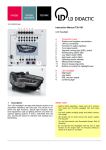
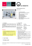
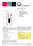
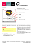
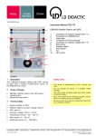
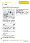
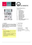
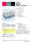
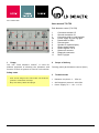
04/11-W2010-Wei User manual 739 750 Park distance control (739 750) 3a 11 1 Usage The unit "Park distance control" is used for didactic purposes of showing the operation and function of such a system as used in real vehicles. 1 2 3 3a 4 5 6 7 8 9 10 11 2 Connector terminal 15 Ground connection 31 Connector trailer or rear fog light Power supply for rear fog light Deactivation of PDC Reverse gear Speaker or optical display Sensor power supply Sensor signals 1 to 4 Ultra sonic sensors Diagnosis connector Rear Fog light Scope of delivery Training panel park distance control (PDC) Safety notes 3 Technical data - Prior to the usage of the unit make sure that the ground is connected correctly! Distance min/max: 0 … 254 cm - Only use safety cables and plugs! Self diagnosis protocol: KW 1281 Power supply VB = +12...+15 V= User manual 4 Page 2/2 Set up and operation 5 Self diagnosis The ECU is by means of the K line self diagnosis capable. Use a diagnosis interface connected to the output 10 for the following diagnosis functions: Set up The system consists of an original ECU J446, 4 40-kHz ultrasonic sensors and an optical and acoustic display. Function The unit requires 12 V=. Operation Plug in the bridging plugs 1, 2, 3a, 4, 6, 7 and 8. After selecting the reverse gear by plugging the appropriate bridging plug (5) the system is activated. By unplugging the system is deactivated again. If the plug for automatic trailer detection (3) is inserted vertically the system cannot be activated because the trailer would be recognized as an obstacle. Change the bridging plug 3 into a horizontal position to switch on the rear fog light (11). If the plug for deactivation (4) is not inserted the system cannot be switched on. If the system is activated it detects obstacles and displays the distance by means of LEDs (plug 6 in a horizontal position) or loudspeaker (plug 6 in a vertical position). The bigger the distance between an obstacle and the rear car the more LEDs lights up respectively the bigger the time between two acoustic signals. Note: Pay attention that there is absolutely nothing within a radius of 2 m in front of the sensors - even a cable in front or beside an sensor can interfere with them. Reducing the distance between the obstacle and the sensors the LEDs turns off one after another from the outer to the inner respectively the time between two signal sounds become shorter. Reading errors (#02) Erasing the fault memory Displaying actual data (#08) Activating actuators (#03) Adaptation (#10) Coding (#07) Data display The following measurement values are available: Group 001 – Distance of sensors 1 to 4 Group 002 – System 1 Group 003 – System 2 Group 004 – Oscillation time Group 080 – System information Actuator test The sound output can be triggered. Adaptation The following parameters can be adapted: Channel 01 – Volume (0…7) Channel 02 – Frequency (0 = 500 Hz, 1 = 660 Hz, 2 = 800 Hz, 3 = 1000 Hz und 4 = 2000 Hz) Coding ?xxxx: Trailer 0 = no trailer 1 = trailer x?xxx: Gear 0 = Manual gear 1 = Automatic gear xx?xx: Country 1 = Rest of the world xxx?x: Chassis 0 = Limousine 3 = Transporter/Multivan xxxx?: Model 2 = VW Polo (9N) 7 = VW Transporter/Multivan (7H) Object Figure 1 LD DIDACTIC GMBH Leyboldstrasse 1 D-50354 Hürth Phone (02233) 604-0 Fax (02233) 604-222 e-mail: [email protected] by LD Didactic GmbH Printed in the Federal Republic of Germany Technical alterations reserved