1
ATLAS.ti 6
Concepts and Functions
2
ATLAS.ti 6 User Manual
Copyright ©2011 by ATLAS.ti Scientific Software Development GmbH, Berlin. All rights reserved.
Version: 349.20111116
Author: Dr. Susanne Friese (QUARC Consulting)
Realization/Programming: Dr. Thomas G. Ringmayr (www.hypertexxt.com)
Copying or duplicating this manual or any part thereof is a violation of applicable law. No part of this manual may be reproduced or
transmitted in any form or by any means, electronic or mechanical, including, but not limited to, photocopying, without written
permission from ATLAS.ti GmbH.
Trademarks: ATLAS.ti is a registered trademark of ATLAS.ti Scientific Software Development GmbH. Adobe Acrobat is a trademark of
Adobe Systems Incorporated; Microsoft, Windows, Excel, and other Microsoft products referenced herein are either trademarks of
Microsoft Corporation in the United States and/or in other countries. Google Earth is a trademark of Google, Inc. All other product
names and any registered and unregistered trademarks mentioned in this document are used for identification purposes only and remain
the exclusive property of their respective owners.
ATLAS.ti 6 USER MANUAL
3
Contents
Introduction..............................................................................................................................9
Main Concepts.......................................................................................................................10
The Hermeneutic Unit (HU)............................................................................................................................................10
Primary Documents (PD or PDoc)...................................................................................................................................11
Primary Document Families (Data Attributes)..................................................................................................................12
Quotations.....................................................................................................................................................................12
Quotations as Layers.......................................................................................................................................................................13
Quotation references.......................................................................................................................................................................13
Types of Quotations........................................................................................................................................................................14
Text Quotations..........................................................................................................................................................................14
PDF Quotations..........................................................................................................................................................................15
Audio and Video Quotations......................................................................................................................................................15
GoogleEarth Quotations.............................................................................................................................................................16
Codes.............................................................................................................................................................................16
Coding Objectives...........................................................................................................................................................................16
Code Reference...............................................................................................................................................................................17
Text Search Tool..............................................................................................................................................................................18
Word Cruncher................................................................................................................................................................................18
Auto Coding Tool............................................................................................................................................................................18
Memos...........................................................................................................................................................................18
Families ..........................................................................................................................................................................19
Nodes, Links & Relations.................................................................................................................................................................19
Network View Manager..................................................................................................................................................................19
Network Editor................................................................................................................................................................................20
Relation Editor.................................................................................................................................................................................20
Link Managers.................................................................................................................................................................................20
Analysis .........................................................................................................................................................................20
Query Tool......................................................................................................................................................................................20
Super Codes....................................................................................................................................................................................20
The Cooccurence Explorer...............................................................................................................................................................21
Codes-Primary Document-Table......................................................................................................................................................21
Team Tools.....................................................................................................................................................................22
User Administration.........................................................................................................................................................................22
Hermeneutic Unit Merger................................................................................................................................................................22
Coding Analyzer..............................................................................................................................................................................22
Export.............................................................................................................................................................................23
RTF..................................................................................................................................................................................................23
PDF..................................................................................................................................................................................................23
XML Generator................................................................................................................................................................................23
SPSS Export.....................................................................................................................................................................................24
Excel Export.....................................................................................................................................................................................24
Graphic Files....................................................................................................................................................................................24
HTML Generator.............................................................................................................................................................................24
Miscellaneous Tools........................................................................................................................................................24
Object Crawler................................................................................................................................................................................24
Object Explorer................................................................................................................................................................................25
Main Steps in Working with ATLAS.ti.....................................................................................26
Data and Project Management.......................................................................................................................................26
ATLAS.ti 6 USER MANUAL
4
Working with Internal Documents (for smaller projects containing only text files) ..........................................................27
The Process.....................................................................................................................................................................28
Data-Level Work.............................................................................................................................................................................28
Conceptual Level Work....................................................................................................................................................................29
General Steps when Working with ATLAS.ti...................................................................................................................29
Project Management..............................................................................................................31
Project Setup..................................................................................................................................................................31
Saving the Project and Controlling Project Setup.............................................................................................................32
Working in Teams...........................................................................................................................................................33
Project administration......................................................................................................................................................................34
Creating user accounts.....................................................................................................................................................................34
Logging in.......................................................................................................................................................................................34
Project File and Project Backup.......................................................................................................................................36
Backup options for the HU..............................................................................................................................................................36
Auto recovery file............................................................................................................................................................................36
“Backup of….” file..........................................................................................................................................................................36
Customizing HU backup options......................................................................................................................................................37
Backup or Transfer of a Project via Copy Bundle.............................................................................................................37
When to create a copy bundle file...................................................................................................................................................37
Consider file size when creating copy bundle files...........................................................................................................................38
Potential problems when creating a bundle file................................................................................................................................39
Installing an acb (atlas copy bundle) file..........................................................................................................................................39
Possible conflicts..............................................................................................................................................................................40
Modifying An Existing Project Setup...............................................................................................................................42
Changing absolute path references to the optimal HUPATH...........................................................................................................42
Exchanging doc or docx files with rtf files (changing paths).............................................................................................................42
What You Should Know About Editing...........................................................................................................................43
Required data file format.................................................................................................................................................................43
What is changed?............................................................................................................................................................................43
Mind the following rules!.................................................................................................................................................................43
Rule No. 1 – Always edit within ATLAS.ti!.......................................................................................................................................43
Rule No. 2: Never delete or modify the auxiliary log file!.................................................................................................................44
How to edit.....................................................................................................................................................................................45
To exit edit mode:............................................................................................................................................................................45
Editing primary documents in team situations .................................................................................................................................45
Editing in teams using a server-based project setup.........................................................................................................................46
Editing in teams when working at different locations.......................................................................................................................46
If the project administrator only is allowed to edit...........................................................................................................................46
Best practice rules for editing primary documents............................................................................................................................47
Basic Coding Techniques........................................................................................................48
Open Coding..................................................................................................................................................................48
Meaning of colored bars in the margin............................................................................................................................................49
Coding via drag & drop..................................................................................................................................................50
Replacing a code..............................................................................................................................................................................50
Modifying the length of a quotation...............................................................................................................................51
To enlarge a segment.................................................................................................................................................................51
To decrease the size of a segment..............................................................................................................................................51
Unlinking a code.............................................................................................................................................................51
Removing a coded segment............................................................................................................................................52
Writing comments for coded segments...........................................................................................................................52
Further coding options provided by the Code Manager..................................................................................................53
Creating a new code...................................................................................................................................................................53
Renaming codes.........................................................................................................................................................................53
Coloring codes............................................................................................................................................................................53
Deleting a code ..........................................................................................................................................................................53
Merging codes............................................................................................................................................................................54
Writing code definitions..............................................................................................................................................................54
Coding other media types...............................................................................................................................................55
Coding a PDF Document.................................................................................................................................................................55
Coding an Image Document............................................................................................................................................................55
Coding audio and video files............................................................................................................................................................55
ATLAS.ti 6 USER MANUAL
5
Step 1: Create an audio or video quotation ...............................................................................................................................55
Step 2: Code an audio or video quotation..................................................................................................................................57
Reviewing audio and video quotations.......................................................................................................................................57
Unlinking codes..........................................................................................................................................................................57
Modifying the length of a video quotation.................................................................................................................................57
Resetting the filter......................................................................................................................................................................57
Describing video quotations to improve outputs..............................................................................................................................58
Renaming video quotations and creating text output.................................................................................................................58
Changing between time and frame references............................................................................................................................58
Making use of quotation comments...........................................................................................................................................58
Family Life..............................................................................................................................59
Purpose of Creating and Working with Families..............................................................................................................................59
Super Families..................................................................................................................................................................................60
Common Procedures......................................................................................................................................................60
The Family Manager........................................................................................................................................................................60
Components of the Family Manager...........................................................................................................................................61
To Open a Family Manager........................................................................................................................................................61
Creating Families.............................................................................................................................................................................62
Adding Members ............................................................................................................................................................................62
Removing Members.........................................................................................................................................................................63
Using Families as Filters....................................................................................................................................................................63
Access the Filter Options via the Main Menu..............................................................................................................................63
Filter Items using the Family Manager........................................................................................................................................63
Removing Families...........................................................................................................................................................................65
Working with Variables: Primary Document Families..............................................................66
PD-Family Table..............................................................................................................................................................................66
Type of Variables........................................................................................................................................................................67
Super families in PD Family Tables..............................................................................................................................................68
Working with Memos.............................................................................................................70
Difference between Memos and Codes...........................................................................................................................................70
How Memos and Comments Differ.................................................................................................................................................70
Memo Content................................................................................................................................................................................71
The Memo Editor.............................................................................................................................................................................71
Create a free memo....................................................................................................................................................................71
Attaching Memos to Data Segments...............................................................................................................................................72
Data Analysis Tools................................................................................................................73
Overview........................................................................................................................................................................73
Analysis Tools..................................................................................................................................................................................73
The Word Cruncher........................................................................................................................................................75
Creating a Word Frequency Report.................................................................................................................................................75
Query Tool.....................................................................................................................................................................77
The Query Tool Window.................................................................................................................................................................77
Operands.........................................................................................................................................................................................79
Basic Operands...........................................................................................................................................................................79
Complex Operands.....................................................................................................................................................................79
Operators........................................................................................................................................................................................79
The Query Language.......................................................................................................................................................................80
Operands First, Operators Next..................................................................................................................................................80
Creating a Query with the Query Tool.......................................................................................................................................80
A Boolean Query........................................................................................................................................................................80
Output of Query Results.................................................................................................................................................................83
Viewing results in context...........................................................................................................................................................83
Creating a Report.......................................................................................................................................................................83
Super Codes....................................................................................................................................................................................84
Creating Super Codes.................................................................................................................................................................85
Restricting Code Queries to Sub Groups .........................................................................................................................................87
Combining group of documents to restrict searchers..................................................................................................................88
ATLAS.ti 6 USER MANUAL
6
Super Families.................................................................................................................................................................89
Co-occurrence Tools.......................................................................................................................................................89
How to open the Co-occurrence Tools............................................................................................................................................89
The Co-occurrence Tree Explorer.....................................................................................................................................................89
The Co-occurrence Table Explorer...................................................................................................................................................91
User-defined content..................................................................................................................................................................92
Inspecting Content.....................................................................................................................................................................94
Explaining frequency count and number of quotations listed......................................................................................................94
Codes-Primary Documents Cross-Tabulation..................................................................................................................95
How to create a Codes-Primary-Documents-Table..........................................................................................................................97
Exporting the entire data set.......................................................................................................................................................97
Preparing tables to compare sub groups of data.........................................................................................................................97
Visualization...........................................................................................................................99
Tools for Visualization and Theory Building.....................................................................................................................................99
Network Views...............................................................................................................................................................99
Nodes and Links............................................................................................................................................................................100
Directed and Non-Directed Links..............................................................................................................................................100
Strong and Weak Links.............................................................................................................................................................102
Network vs. Network View.......................................................................................................................................................102
Node Types...............................................................................................................................................................................102
Relations........................................................................................................................................................................................102
Link vs. Relation........................................................................................................................................................................103
The Role of Relations................................................................................................................................................................104
The Network Editor ..................................................................................................................................................................104
Basic Network View Procedures.....................................................................................................................................................105
Creating Network Views...........................................................................................................................................................105
To create a new Network View............................................................................................................................................105
To open a Network View on an Object................................................................................................................................106
Adding Nodes to a Network View............................................................................................................................................106
Via Drag & Drop..................................................................................................................................................................106
Via the Import Nodes dialog.................................................................................................................................................107
Linking Nodes...........................................................................................................................................................................108
To link two nodes using the toolbar icon..............................................................................................................................108
Cutting Links.............................................................................................................................................................................109
Modifying Links........................................................................................................................................................................110
To remove nodes from a Network View...............................................................................................................................110
To delete nodes from a Network View.................................................................................................................................110
Simple analytic functions...........................................................................................................................................................111
Import Node Neighbors........................................................................................................................................................111
Import Co-occurring Codes..................................................................................................................................................111
Creating Output............................................................................................................................................................................111
Printing Networks.....................................................................................................................................................................112
Network Views for other Applications.......................................................................................................................................112
Copy to Clipboard................................................................................................................................................................112
Save Network View as Graphic File......................................................................................................................................112
Hypertext.....................................................................................................................................................................114
Representing the “Rhetoric of Text”.............................................................................................................................................114
Benefits of Hypertext.....................................................................................................................................................................115
What codes cannot do..............................................................................................................................................................115
Graphical Hyperlink Maps.........................................................................................................................................................116
General Procedures...................................................................................................................................................................117
Star or Chain connections.....................................................................................................................................................117
Hyperlinks in the Quotation Manager.......................................................................................................................................118
Hyperlinks in the Margin Area..................................................................................................................................................118
Creating Hyperlinks.......................................................................................................................................................................119
Creating Hyperlinks using the context menu............................................................................................................................119
To create a chain:.................................................................................................................................................................119
To create a star:....................................................................................................................................................................120
Creating Hyperlinks in the Quotation Manager........................................................................................................................120
Defining New Hyperlink Relations............................................................................................................................................121
Traversing Hyperlinks.....................................................................................................................................................................121
To traverse hypertext links using the margin area................................................................................................................121
The "In-Place" Method for audio- and video hyperlinks..........................................................................................................122
To display hyperlinked neighbors "in-place"........................................................................................................................122
ATLAS.ti 6 USER MANUAL
7
Generating Output...............................................................................................................124
Overview......................................................................................................................................................................124
General Procedure........................................................................................................................................................125
Output Destinations......................................................................................................................................................................125
Report Layout................................................................................................................................................................................125
Common Header......................................................................................................................................................................125
Sorts & Filters............................................................................................................................................................................126
Restricting Output to Selected Objects.....................................................................................................................................126
Creating Reports with the XML Converter....................................................................................................................127
Working with Style Sheets.............................................................................................................................................................127
Example: Code book ...............................................................................................................................................................128
Export & Import...................................................................................................................130
SPSS Export..................................................................................................................................................................130
Export & Import using XML..........................................................................................................................................130
Exporting and Importing Codes in XML ........................................................................................................................................131
Exporting Codes.......................................................................................................................................................................131
Importing Codes.......................................................................................................................................................................131
HTML Export................................................................................................................................................................131
Exporting an HU as HTML Document...........................................................................................................................................132
Export and Import of Documents and their Attributes...................................................................................................134
Appendix..............................................................................................................................135
Useful Resources...........................................................................................................................................................135
The ATLAS.ti Website....................................................................................................................................................................135
Quick Tour....................................................................................................................................................................................135
Full Manual and “How To” Documents........................................................................................................................................135
Video tutorials...............................................................................................................................................................................136
Library...........................................................................................................................................................................................136
Knowledge Base............................................................................................................................................................................136
Social Media..................................................................................................................................................................................136
YouTube...................................................................................................................................................................................136
Facebook..................................................................................................................................................................................136
Twitter......................................................................................................................................................................................136
Newsroom.....................................................................................................................................................................................137
The Help Menu..............................................................................................................................................................................137
Getting Support.............................................................................................................................................................................137
Frequently Asked Questions..........................................................................................................................................................138
Forum............................................................................................................................................................................................138
Mailing List Archive.......................................................................................................................................................................138
Troubleshooting............................................................................................................................................................139
Help with Data Management Problems.........................................................................................................................................139
Documents cannot be accessed................................................................................................................................................139
Embedded Objects Cannot be Activated..................................................................................................................................139
Cannot Enter Edit Mode for Primary Documents......................................................................................................................139
Reporting Bugs.........................................................................................................................................................................139
Service Packs & Patches – Live Update..........................................................................................................................141
To run the software as administrator (for VISTA and Windows 7 users)........................................................................................141
Live Update Settings......................................................................................................................................................................141
Glossary........................................................................................................................................................................143
Authorship.....................................................................................................................................................................................143
Auto Coding Tool..........................................................................................................................................................................143
Backup...........................................................................................................................................................................................143
Codes............................................................................................................................................................................................143
Coding Analyzer............................................................................................................................................................................143
Comments.....................................................................................................................................................................................143
Cooccurence Explorer....................................................................................................................................................................144
Copy Bundle..................................................................................................................................................................................144
Families..........................................................................................................................................................................................144
Family Manager.............................................................................................................................................................................145
Hermeneutic Unit..........................................................................................................................................................................145
Hermeneutic Unit Editor................................................................................................................................................................145
ATLAS.ti 6 USER MANUAL
8
Hermeneutic Unit Merger..............................................................................................................................................................145
HTML Generator...........................................................................................................................................................................145
Link Managers...............................................................................................................................................................................145
Margin Area..................................................................................................................................................................................146
Memos..........................................................................................................................................................................................146
Network Editor..............................................................................................................................................................................146
Network Views..............................................................................................................................................................................146
Network View Manager................................................................................................................................................................146
Nodes, Links & Relations...............................................................................................................................................................146
Object Crawler..............................................................................................................................................................................147
Object Explorer..............................................................................................................................................................................147
Object Managers...........................................................................................................................................................................147
Primary Documents.......................................................................................................................................................................147
Primary Document Families (Data Attributes)................................................................................................................................147
Project Transfer..............................................................................................................................................................................148
Query Tool....................................................................................................................................................................................148
Quotations....................................................................................................................................................................................148
Relation Editor...............................................................................................................................................................................149
Super Code....................................................................................................................................................................................149
Text Editor.....................................................................................................................................................................................149
Text Search Tool............................................................................................................................................................................149
Variables........................................................................................................................................................................................149
Word Cruncher..............................................................................................................................................................................149
XML Converter..............................................................................................................................................................................150
XML Generator..............................................................................................................................................................................150
User Administration.......................................................................................................................................................................150
ATLAS.ti 6 USER MANUAL
INTRODUCTION
9
Introduction
This document provides a quick overview of the basic concepts underlying the
work with ATLAS.ti. It is designed to provide the “big picture,” and in doing so
aims at helping you to quickly get your bearings when first starting out your
work with the program.
Proper understanding of the central concepts and functions is key to avoiding
some of the most common pitfalls. We have therefore compiled those passages
from the full manual that (a) introduce the major concepts and their
corresponding functions (such as codes, quotations, memos, families, etc.), (b)
provide practical tips in how to approach your projects (e.g. data and project
management), and (c) have added a comprehensive glossary that provides
succinct overviews of all the central terms, concepts, and functions that you
encounter in your work with ATLAS.ti.
The full manual is available from http://manual.atlasti.com
We also recommend the following essential resources for more detailed
information, additional help, and for practical guidance in getting started:
Quick Tour:
http://quicktour.atlasti.com
Free Webinars:
http://webinars.atlasti.com
Video Tutorials:
http://youtube.atlasti.com
Knowledge Base:
http://kb.atlasti.com
Training Center:
http://training.atlasti.com
Workshops:
http://workshops.atlasti.com
Support Center:
http://support.atlasti.com
ATLAS.ti 6 USER MANUAL
MAIN CONCEPTS
10
Main Concepts
The Hermeneutic Unit (HU)
The Hermeneutic Unit (HU), provides the data structure for each project in
ATLAS.ti. The name was chosen to reflect the approach we have taken when
building a support tool for data interpretation. There was no intention to
frighten potential users with this admittedly tongue-twisting name.
Get acquainted with this concept!
If you understand the HU concept, then you understand almost everything that
is necessary to work with ATLAS.ti!. And, in spite of its impressive name, it is
simple and practical to use.
Everything that is relevant to a particular project (e.g., a research topic) is part
of the HU and resides in the electronic environment! For instance, the Primary
Documents representing the data sources, the quotations, the codes, the
conceptual linkages (families, networks), and the memos, etc., are all part of
one HU.
One obvious advantage of this bundling is that the user only has to deal with
and think of one entity. Activating an HU is the straightforward selection of a
single file; all associated material is then activated automatically.
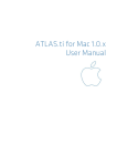
The lowest level of an HU contains the Primary Documents, followed closely by
the "quotations" as selections of the Primary Documents. On the next level,
codes refer to quotations. Memos - you meet them everywhere.
The lowest level of an HU contains the PDs, followed closely by the quotations
as selections of PDs. Codes refer to quotations. Memos - you meet them
everywhere.
ATLAS.ti 6 USER MANUAL
MAIN CONCEPTS
11
Figure 1: The hierarchy of objects inside a Hermeneutic Unit
An HU can become a highly connected entity, a dense web of primary data,
associated memos and codes, and interrelations between the codes and the
data. To find your way through this web, ATLAS.ti provides powerful browsing,
retrieval and editing tools.
Primary Documents (PD or PDoc)
Primary Documents represent data sources. These can be text, image, audio,
video or geographic materials that you wish to interpret. The content of PDocs
is usually stored in data files on your computer.
This content is turned into primary documents by assigning them to an HU.
The source files remain external to the HU. It is however also possible to create
internal text documents and to assign memos as a internal PD. When using
data files as external sources for your PDs, then you need to make sure that
access to these sources is provided. This means the source file has to remain at
the referenced location and should not be renamed or moved; otherwise the
HU cannot find it. To not endanger the integrity of your coding, data sources
should also not be changed outside of ATLAS.ti. ATLAS.ti offers an edit mode
in case you need to make changes to your data sources. See below “Data and
Project Management”.
ATLAS.ti 6 USER MANUAL
MAIN CONCEPTS
12
Primary Document Families (Data Attributes)
Families in ATLAS.ti are a group of objects (see the entry “Families” below).
Primary document families fulfill a special function as they can be regarded as
quasi dichotomous variables. You can group all female interviewees into a PD
family called “female”. All male interviewees into a PD family called “male”.
You can do the same for different professions, marital status, education levels,
etc. The classification is a 0 / 1 classification. 1 means the document is part of a
particular group; 0 means it is not part of the group.
Following a special syntax, you can also create PD families that can be
imported or exported as variables with two or more characteristics based of an
Excel table like Gender::male and Gender::female.
PD Families can be later used to restrict code based searches like: Show me all
data segments coded with “attitude towards the environment” but only for
females who live in London as compared to females who live in the country
side. You can also use PD families as filer to reduce other type of output like a
frequency count for codes across a particular group of documents. See the
chapter “Family Life” in the full manual.
Quotations
A quotation is a segment from a PD that is interesting or important to the user.
In textual documents, a quotation is an arbitrary sequence of characters
ranging from a single character, a word, a sentence, or a paragraph up to the
entire data file.
Free quotations resemble passages "scribbled" in the margin of a book.
Usually quotations are created by the researcher. However, if repetitive words
or phrases are found in the text, the Auto-Coding feature can be used to
automatically segment these quotations and assign a code to them. When a
quotation is created, ATLAS.ti automatically assigns an identifier to it. This
identifier is built from the index of the primary text to which it belongs and the
first 30 letters (note that a different length can be set via Preferences) of the
text segment, e.g., "1:21 Therefore a more efficient fil....". The identifier is
displayed in list windows and printouts. For graphic, audio, and video
segments, the original file name of the PD is chosen as an identifier.
Although the creation of quotations is almost always part of a broader task
like coding or writing memos, "free" quotations can be created that
indicate interesting parts in the primary data for which a meaningful
classification has not yet been found. See “The Textual Level – Basic
Functions” in the full manual.
ATLAS.ti 6 USER MANUAL
MAIN CONCEPTS
13
Quotations as Layers
Quotations are stored inside the HU, independent of the document to which
they belong.
Quotations need to be regarded as a transparent layer on top of a document.
Quotations are stored independently of the PD inside the HU. Technically
speaking, a quotation consists of the identifier (a number) and a pair of
coordinates that specify the beginning and end of the quotation. The content
of a PD file (the data source) is therefore not altered by the creation, deletion,
or modification of quotations.
Read more on quotations in our library:
http://downloads.atlasti.com/library/Maietta_2009-05_6.pdf
Quotation references
The bars in the margin mark the length of the quotation graphically. The entry
in the quotation field shows a textual reference for the quotation. It consists of
the following elements: ID, name, start and end position.
ID: The quotation ID is composed of the number of its P-Doc and a second
number indicating when the quotation was created. The ID 8:1 means that the
quotation is from P-Doc 8 and is the first one that was created in this
document. The reason for the chronological numbering is to do with the fact
that you will not necessarily code a document from the first line to the last. You
will jump between passages and modify or delete some quotations during the
coding process. A linear numeration would have to be updated with every
single quotation that is inserted, which would take up unnecessary
computation capacity. Sorting the quotations by their start position, for
example, offers a clear linear view of your quotes. Recently an option was
added to change the chronological numbering to a sequential order if need be
(QUOTATIONS / MISCELLANEOUS / RENUMBER ALL TO DOCFLOW). This can for example be
useful when coding open ended questions from survey data and you want to
keep the cases in synch with the cases in the SPSS file.
Name: The name shows the first 30 characters of a textual quotation. This is
the default setting which can be changed under EXTRAS / PREFERENCES / GENERAL
PREFERENCES. Quotations based on image, audio or video files show the file name.
The name of a quotation can be renamed. This is a useful option for image,
audio and video quotations, as we will see below.
Start and end positions: The figures in brackets after the quotation name show
the location (start and end position) in the document. For textual quotations,
ATLAS.ti 6 USER MANUAL
MAIN CONCEPTS
14
the reference given is to the paragraph numbers within which the coded
segment occurs. (9:9) thus means that the quotation starts and ends in
paragraph 9.
For image files, the rectangular area marked as the quotation is referenced.
Audio quotes use a time reference, and for video quotations you can choose
between time or frame numbers.
References for PDF quotations consist of: page number and number of
characters on the page for start and end positions. In case the document
contains columns, the column number is provided as well.
Video tutorial: http://www.atlasti.com/video/article/creatingquotations.html
Types of Quotations
In accordance with the six different types of PDs, there are also six different
types of quotations:
Text Quotations
A textual quotation originates from an arbitrary sequence of selected
characters.
Textual quotations represent (for the computer) a sequence of characters
("strings") and can be of arbitrary size. Sentences, speech turns, or paragraphs
are often the basis for the length of textual quotations. Only text offers enough
"syntactical clues" to allow for searches for the occurrence of specific evidence
that may support a concept. Text also offers the option for automatic
segmentation as used by the Auto-Coding procedure (see the section on “The
Auto-Coding Tool” in the full manual).
Graphic Quotations
The creation, activation, and display of graphical quotations has similarities
with, but also differs from, their textual counterparts. A graphical quotation is a
rectangular region inside a graphical PD. From its data structure, it is identical
to textual quotations since their main attributes are also the PD identifier and
two coordinates that mark the beginning and end, defining a rectangle through
its upper left and lower right corner.
ATLAS.ti 6 USER MANUAL
MAIN CONCEPTS
15
Handling graphical quotations is analogous to marking text passages in a
textual document. See “reating Graphical ” on page 158.
PDF Quotations
PDF quotations can be of a textual or of a graphical nature. The quotation
references for textual quotations indicate the page number and the start and
end position on the basis of character counts For example: (31:1537-31:1745)
means that this quotation is from page 31, starting at character 1537 and
ending at character 1745. The reference for coded images indicates the
position of the quotation within the PDF file like: (@422-@618).
Read more about using PDF documents in ATLAS.ti in our library:
http://downloads.atlasti.com/library/Friese_2009-05_18.pdf
Audio and Video Quotations
Audio and video quotations can be as short as a few milliseconds. The length of
a quotation can be selected on a time line. Segment starting points and length
are displayed in the following formats:
milliseconds / HH:MM:SS:ms / frames (for videos)
ATLAS.ti 6 USER MANUAL
MAIN CONCEPTS
16
GoogleEarth Quotations
When creating a GE quotation, you see the ATLAS.ti icon on the GE map. It is
linked to one location and thus is different from all other types of quotations
that present a range. The quotation ID shows either the name of the document
or the feature's name (if applicable). In addition the geographic reference of
the marked location is provided.
See our library for an example on how to work with GoogleEarth data:
http://downloads.atlasti.com/library/Cisneros_2009-03_17.pdf
Codes
The term code is used in many different ways. First we would like to define
what that term means in qualitative research and then in ATLAS.ti.
Coding Objectives
From a methodological standpoint, codes serve a variety of purposes. They
capture meaning in the data. They also serve as handles for specific occurrences
in the data that cannot be found by simple text-based search techniques.
Codes are used as classification devices at different levels of abstraction in order
to create sets of related information units for the purpose of comparison (e.g.,
a concept like "Coping Strategy").
Keep code names brief and succinct. Use the comment pane for longer
elaborations.
From a "low level" tool perspective, codes are typically short pieces of text
referencing other pieces of text, graphical, audio, or video data. Their purpose
is to classify an often large number of textual or other data units.
ATLAS.ti 6 USER MANUAL
MAIN CONCEPTS
17
In the realm of information retrieval systems, the terms "index," "indexing," or
"keyword" are often used for what we call "code" or "coding".
The length of a code should be restricted and should not be too verbose. If
textual annotations are what you want, you should use quotation comments
instead.
The technical aspects of coding are described under Textual Level – Basic
Functions, p. 116 ff in the full manual.
You find information on how to structure a code list in ATLAS.ti in our library:
• http://downloads.atlasti.com/library/Friese_2009-09_1.pdf
• http://downloads.atlasti.com/library/Woolf_2007-03_13.pdf
Video Tutorials:
• http://www.atlasti.com/video/article/coding-basics.html
• http://www.atlasti.com/video/article/code-management-ii.html
• http://www.atlasti.com/video/article/the-margin-area-part-i.html
• http://www.atlasti.com/video/article/the-margin-area-part-ii.html
Code Reference
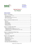
Figure 2: Codes in ATLAS.ti
The selected code word is written next to the quotation bar in the margin. You
can recognize codes by the yellow diamond symbol.
The entry in the drop-down list in Figure 2: Codes in ATLAS.ti reads: “test 1
{1-0}”. The first number shows the frequency (how often the code has been
applied). It gives you some information on the groundedness of a code, i.e.
how relevant this code is in the data. The second number the density (how
many other codes this code is linked to). Hence the code “Test 1” has been
used only once so far and it is not yet linked to any other code.
To learn more about linking codes, read the entry on the Network View
function and take a look at the Quick Tour.
ATLAS.ti 6 USER MANUAL
MAIN CONCEPTS
18
Text Search Tool
From simple string matching to sophisticated pattern match (GREP) and
category search, all is available in the Text Search Tool. See the chapter on
“Special Tools” in the full manual.
Word Cruncher
The Word Cruncher counts all words in textual PDs. The count can be limited
to one PD only. To clean up the count, a stop list can be defined to exclude
special symbols or words like ‘and,’ ‘or,’ ‘the,’ etc. The result can be displayed
in an Excel table. See the chapter on “Special Tools” in the full manual.
Auto Coding Tool
If the text itself contains important key words, the Auto Coding Tool scans the
text and automatically assigns a pre-selected code to matching text passages. If
so desired, the process can be controlled by manual confirmation of each
action. See the chapter on “Special Tools” in the full manual.
Memos
Memos capture your thoughts regarding the text and are an important device
for creating theory. A "memo" is similar to a code, but usually contains longer
passages of text.
A memo may "stand alone" or it may refer to quotations, codes, and other
memos. They can be grouped according to types (method, theoretical,
descriptive, etc.), which is helpful in organizing and sorting them. Memos may
also be included as the objects of analysis by assigning them as PDs.
See the section on memo writing under “Textual Level – Basic Functions”, p.
128 ff. in the full manual. – Also read these library articles:
• http://downloads.atlasti.com/library/Friese_2009-09_1.pdf
• http://downloads.atlasti.com/library/Friese_2008-12_8.pdf
ATLAS.ti 6 USER MANUAL
MAIN CONCEPTS
19
Families
Families are a way to form clusters of PDs, codes, and memos for easier
handling of groups of codes, memos, and PDs. Primary Document families can
be regarded as attributes or variables.
Families can be combined using logical operators similar to codes and Super
Codes. For more detail, see the chapter “Family Life” in the full manual.
Network Views
Network Views are a bit more sophisticated than families. They allow you to
conceptualize the structure by connecting sets of similar elements together in a
visual diagram. With the aid of Network Views you can express relationships
between codes, quotations, and memos. PDs, families and even Network Views
can also be “nodes” in a network view.
Nodes, Links & Relations
A node is any object that is displayed in a Network View. You can change their
look and move them around in the Network Editor.
Relations are link prototypes used to create a link between two codes or
between two quotations. An example is the “is-a” (ISA) relation, which is
frequently used to link concepts of different abstraction level (e.g., DOG <isa>
MAMMAL).
Network View Manager
The Network View Manager contains a list of all previously constructed and
saved Network Views. It can be used to create new Network Views, to access
or delete existing ones, or to write and edit comments.
ATLAS.ti 6 USER MANUAL
MAIN CONCEPTS
20
Network Editor
The Network Editor displays and offers all editing capability to construct and
refine semantic networks. In addition, it allows the visual creation and traversal
of hypertext structures.
Relation Editor
When the built-in relations that are used to connect objects in Network Views
are not sufficient, you can edit them or create new ones using the Relation
Editor.
Link Managers
The Link Managers provide an overview of all code-code links and of all
quotation-quotation links you have created.
The full manual has further information on the network function under “The
Conceptual Level – Networks”, starting on page 211.
Video tutorials:
• http://www.atlasti.com/video/article/network-building-i.html
• http://www.atlasti.com/video/article/network-building-ii.html
• http://www.atlasti.com/video/article/network-building-iii.html
• http://www.atlasti.com/video/article/hyperlinks.html
Analysis
Query Tool
For more complex search requests, the Query Tool is at your disposal. Here you
can formulate search requests that are based on combinations of codes using
one or a combination of 14 different operators (Boolean, semantic and
proximity operators). See the chapter on “Special Tools” in the full manual.
Video Tutorial: http://www.atlasti.com/video/article/the-query-tool.html
Super Codes
A Super Code differs from a standard code. A standard code is directly linked
with the quotations to which it is associated, while a Super Code is a stored
ATLAS.ti 6 USER MANUAL
MAIN CONCEPTS
21
query, thus provides an answer to a question (in the best case) that typically
consists of several combined codes. See the chapter on the Query Tool in the
full manual.
The Cooccurence Explorer
The Cooccurence Explorer is more exploratory than the Query Tool. Rather
than determining the codes yourself, you can ask ATLAS.ti which codes happen
to co-occur in the margin area. The output can be viewed in form or a tree
view or a table view (CTE: Cooccurence Table Explorer). The CTE provides
frequency of co-occurrence and a a coefficient measuring the strength of the
relation is calculated. The such a coefficient is only appropriate for some type of
data, its display can be activated or deactivated. It is always possible to access
the data behind the frequency counts or coefficient.
You find this function under the TOOLS menu.
More information on how the coefficient in the CTE is calculated can be found
here: http://www.atlasti.com/395.html. In addition, the tool is explained in
the manual addendum (V6 stuff).
Codes-Primary Document-Table
The Codes-Primary-Document Table contains the frequency of codes across
documents. It can be exported as Excel compatible table. Optional, the table
cells can also contain the word counts for the quotations per code across
documents. This option can be found under the Codes / Output menu.
ATLAS.ti 6 USER MANUAL
MAIN CONCEPTS
22
Team Tools
User Administration
Manage the ATLAS.ti user database through the user administration tool. This
is a prerequisite for collaborative work, but is also useful to individual users
through personalizing the login or protecting an HU with a password User
Management options can be found under the Extras menu. See also the full
manual, the chapter on “User Management”).
Hermeneutic Unit Merger
This tool merges different HUs. A variety of options to control the merge
strategy are offered. You find this function under the Tools menu. Further
information is provided in the chapter “Merging Hermeneutic Units” in the full
manual.
Coding Analyzer
The Coding Analyzer is helpful after merging HUs. It tests for redundant codes,
i.e., codes used more than once for data segments that overlap or are
embedded in one another. You find it under the Tools menu.
ATLAS.ti 6 USER MANUAL
MAIN CONCEPTS
23
Export
RTF
There are output options for each of the main objects in ATLAS.ti: Primary
Documents, Quotations, Codes and Memos. You find it under the respective
menus. You can output a list of primary documents along with their comments,
all or selected quotations with our without comments, quotations by codes (via
the Codes / Output menu), a list of all codes, code-neighbors lists, etc. For
memos, you can either output just a list of your memos, the content of memos
or the content including the linked objects.
PDF
You can print out coded documents as you see them on the screen with the
codes in the margin area. This option will soon also be available for PDF and
image files (in a version higher than 6.2.23). You find it under DOCUMENTS /
OUTPUT / PRINT WITH MARGIN.
XML Generator
The XML generator exports all information contained in an HU in XML format.
This universal, open data format allows for a wide variety of possibilities for
display, processing, and even integration of your data with external
applications. Click on the XML button in the main tool bar to explore the
options.
Further detail is provided in the full manual and on our website:
http://www.atlasti.com/xml.html
XML Converter
The XML Converter lists HUs saved in XML format and applies so-called "style
sheets" (miniature programs written in XSLT) to the XML files. The user may
edit the supplied style sheets or add new ones. Just to mention a few outputs
that you can create using the XML style sheets:
•
A nicely formatted code book (Modern codes (commented only)
•
A tag cloud for the elements in the HU (HU tag cloud)
•
A list of quotations sorted by documents (Quotations List by Primary
Documents)
•
The content of quotations sorted by codes (Print Codes in Full)
Use “version 1” style sheets in ATLAS.ti v.5.x and “version 2” style sheets in
ATLAS.ti v.6.x.
ATLAS.ti 6 USER MANUAL
MAIN CONCEPTS
24
SPSS Export
You can export your coded data as SPSS syntax file. When executed in SPSS,
your quotations become cases and your codes and code families variables. In
addition further identifying information in form of variables is provided like the
primary document number for each case, start and end position and creation
date. These variables allow you to aggregate your data in SPSS if needed.
If you need a less detailed output, see „Code-Primary-Document-Table“. The
table provides an output that is already aggregated by primary documents.
Excel Export
The frequency of codes across documents (Codes / Output / Codes-Primary
Document Table), the results of the Cooccurence Table Explorer (Tools /
Cooccurence Tools, and the word frequency count (see Word Cruncher) can be
exported as Excel compatible file.
Graphic Files
Network Views can be saved as bmp or emf files: Open a network view and
select Network / Save as Graphic File.
HTML Generator
Publishing online or just creating a printout from a project is available with the
HTML generator. The results can be viewed platform independent with any
Web browser. This option can be found under the Extras menu and is best
suitable for exporting your entire project. HTML preferences can be set under
Extras / Preferences / HTML Preferences.
Miscellaneous Tools
Object Crawler
With the Object Crawler, you can search all of the parts of your project within
ATLAS.ti that contain text. Searches are not restricted to just textual PDs:
codes, memos, quotations, all families, code-code links, hyper-links, and the
HU can be searched. In addition, the scope of the search can be limited to
certain fields. You find the Object Crawler under the Tools menu.
ATLAS.ti 6 USER MANUAL
MAIN CONCEPTS
25
Object Explorer
The Object Explorer displays all the elements of an HU in a strictly hierarchical
manner, even if the structures are non-hierarchical, or even cyclic. You find the
Object Explorer under the Tools menu.
ATLAS.ti 6 USER MANUAL
MAIN STEPS IN WORKING WITH ATLAS.TI
26
Main Steps in Working with ATLAS.ti
Data and Project Management
Figure 3: From data to structure
A first important but often neglected phase is data and project management.
The first step is data preparation. You find more information on supported file
formats in the section “Preparing Documents” in the full manual.
Apart from analyzing your data, you also manage digital content and it is
important to know how the software does it (See the section “How ATLAS.ti
handles documents” on page 93ff in the full manual. We also advise to read
the chapter on project management, p. 270ff).
In order to give you an idea what kinds of issues might come up, here is a list
of issues that are important to consider:
• Where will you store your data?
• Do you want to work with external or internal documents?
• Do you want to link your data transcripts to the original audio and video
sources? (Version 6 manual addendum)
• Do you think you might have to move your project at some point? (See
“Project Maintenance, p. 282ff).
ATLAS.ti 6 USER MANUAL
MAIN STEPS IN WORKING WITH ATLAS.TI
27
• Should data be edited after it is assigned to ATLAS.ti?
See the section on “Editing primary documents” in the full manual, p. 78ff.)
Also: http://downloads.atlasti.com/library/Friese_2009-09_2.pdf
• Do you need data to be shared among team members?
For further information on team project management see the chapter on
“Collaboration“ (p. 262ff) and “Merging Hermeneutic Units” (p. 289ff).
• Where and how can you create project backups?
See “Project Maintenance, p. 282ff.)
The One-Folder Setup - For Single Users and Teams
Storing all data files to be analyzed and the ATLAS.ti project file in one folder is
the easiest and most flexible way to set up a project. Even when working with
video files or other sizable data sets that you may store on an external hard disk
or server, you can still use this setup. You just need to save the ATLAS.ti project
file (the HU) on the external disk or server as well. This scenario also works well
for team projects. Each team member either stores the project folder with all of
the data on his or her computer, or the project folder is kept on a server. In the
team project case a few more issues need to be considered, like working with
user accounts and different sub-HUs. Teams can follow the instructions for the
sample data set and then continue to read the additional information for team
projects.
Working with Internal Documents (for smaller projects
containing only text files)
Using version 6.2 or higher, it is possible to create internal documents. This
means you no longer have to worry about document references and document
locations. Your ATLAS.ti project consists of a single data file, the HU. This
project setup can be used for smaller projects where the data material is
comprised of text documents only.
As this function was recently added to the software, it is difficult to know yet
how small is small. A test project containing 40 interviews that amounted to a
total size of 5.3 MB and 1800 pages of text outside ATLAS.ti, resulted in a
coded HU file of 730k. Thus, working with 100 internal files should still be ok.
This approach is also a good option for working with sensitive data material.
When saving the HU, the data material is highly compressed and therefore
unreadable outside ATLAS.ti. In addition, the HU can be password-protected.
This should make unauthorized access reasonably difficult.
This is how it works: you generate a new empty text document within ATLAS.ti
and then you copy and paste the contents that you want to analyze into it:
• Open ATLAS.ti and select the main menu option DOCUMENTS / ASSIGN / NEW
TEXT DOCUMENT.
ATLAS.ti 6 USER MANUAL
MAIN STEPS IN WORKING WITH ATLAS.TI
28
• Enter a name for the document into the window that opens.
• The document is loaded in edit mode.
• Copy the text you want to analyze and paste it into the primary document.
• Protect the document by quitting edit mode. You will find the edit mode
button in the second toolbar below the main menu on the left hand side.
Click on the pen and select the option Save and Leave Edit Mode.
• Proceed in the same way with all other documents that you want to analyze.
• Save the HU file.
Make sure that you always create a backup copy of this file and store it at a
safe location!
See “Assigning and Handling Primary Documents” in the full manual for
further details, and http://downloads.atlasti.com/library/Friese_200909_2.pdf from our library. - Video tutorial:
http://www.atlasti.com/video/article/assigning-documents.html
The Process
There are two principal modes of working with ATLAS.ti, the data level and the
conceptual level. The Data Level includes activities like segmentation of data
files; coding text, image, audio, and video passages; and writing comments and
memos. The Conceptual Level focuses on querying data and model-building
activities such as linking codes to networks, in addition to writing some more
comments and memos.
Data-Level Work
Data-level research activities include segmenting the data that you have
assigned to a project into quotations, adding comments to respective passages
(note-making/annotating), and coding selected text passages or data
segments, secondary materials, annotations, and memos to facilitate their later
retrieval. The act of comparing noteworthy segments leads to a creative
conceptualization phase that involves higher-level interpretive work and
theory-building.
ATLAS.ti assists you in all of these tasks and provides a comprehensive
overview of your work as well as rapid search, retrieval, and browsing
functions.
Within ATLAS.ti, initial ideas often find expression through their assignment to
a code or memo, to which similar ideas or text selections also become assigned.
ATLAS.ti provides the researcher with a highly effective means for quickly
retrieving all data selections and notes relevant to one idea.
ATLAS.ti 6 USER MANUAL
MAIN STEPS IN WORKING WITH ATLAS.TI
29
Read more detail in the section on the “Data Level Basic Functions” in the full
manual.
Conceptual Level Work
Beyond coding and simple data retrieval:
ATLAS.ti allows you to query your data in lots of different ways, combining
complex code queries with variables, exploring relationships between codes
and to visualize your findings using the network tool.
ATLAS.ti allows you to visually "connect" selected passages, memos, and
codes into diagrams that graphically outline complex relations. This feature
virtually transforms your text-based workspace into a graphical "playground"
where you can construct concepts and theories based on relationships between
codes, data segments, or memos.
This process sometimes uncovers other relations in the data that were not
obvious before and still allows you the ability to instantly revert to your notes
or primary data selection.
For more detail, see the section “The Conceptual Level” in the full manual.
General Steps when Working with ATLAS.ti
The following sequence of steps is not mandatory, but describes a common
"script:"
• Create a project, an "idea container," meant to enclose your data, all your
findings, codes, memos, and structures under a single name. We call this a
"Hermeneutic Unit" (HU). A more detailed explanation is provided below.
• Next, assign documents, text, graphic, audio and video files, and Google
Earth as so called Primary Documents (PDs) to the HU. The data files
become the source material for your project’s primary data and can be
located anywhere on your computer or a network. For ease of data
management, it is however recommend storing all data and the ATLAS.ti
project file, the HU, within one folder.
• Read and select text passages or identify areas in an image or select
segments on the time line of an audio or video file that are of further
interest, assign key words (codes), and write comments and memos that
contain your thinking about the data. We call this the Data-Level working
phase.
• Compare data segments based on the codes you have assigned; possibly
assign more data files to the project.
• Organize PDs, codes, and memos using “Families” (see the chapter on
“Family Life“ in the full manual for further information).
ATLAS.ti 6 USER MANUAL
MAIN STEPS IN WORKING WITH ATLAS.TI
30
• Query the data based on your research questions utilizing the different tools
ATLAS.ti provides. The key words to look for are: simple retrieval, complex
code retrievals using the query tool, simple or complex retrievals in
combination with variables via the scope button, the cooccurence explorer
(tree and table explorer), the codes-primary document table, Excel and SPSS
export of frequency counts for further statistical analysis.
• Build semantic, prepositional or terminological networks from the codes you
have created. These networks, together with your codes and memos, form
the framework for emerging theory. Look for the chapter “Network Views“
in the full manual.
Figure 4: The general process of working with ATLAS.ti
• Finally, compile a written report based on the memos you have written
throughout the various phases of your project and the networks you have
created and even publish your project as a World Wide Web document or
an individual presentation using XML. See “HTML Export“ and “Creating
Reports with the XML Converter“ in the full manual. For your convenience a
number of style sheets are already provided. Click on the XML button in the
tool bar to explore them.
See the following online resources for examples on how to work with
ATLAS.ti:
• http://downloads.atlasti.com/library/Casasempere_2007-07_11.pdf
• http://www.qualitativeresearch.net/index.php/fqs/article/viewArticle/1632/3149
• http://atlasmalaysia.wordpress.com/2010/09/01/howtolr/
ATLAS.ti 6 USER MANUAL
PROJECT MANAGEMENT
31
Project Management
Project Setup
Create a new folder somewhere on your computer / server / external drive.
Let's call it your ATLAS.ti project folder.
Move a copy of all data you want to analyze into this new folder. If you have
lots of data, you can create sub folders within the main folder where you store
the data (see Figure 5: One-folder setup and Figure 6: One-folder setup with
sub folders below).
Open ATLAS.ti. Check the title bar. If the last used HU is open and not a new
one, select the main menu option FILE / CLOSE. The text in the title bar should
read: New Hermeneutic Unit.
Select the main menu option DOCUMENTS / ASSIGN / ASSIGN.
A file loader window opens. Navigate to your project folder. Select all
documents in the folder. To select all documents, you can use the key
combination Ctrl+A.
Click on the open button (it will appear in the language of your Windows
system).
Figure 5: One-folder setup
ATLAS.ti 6 USER MANUAL
PROJECT MANAGEMENT
32
Figure 6: One-folder setup with sub folders
Open the the drop down field for P-Docs and left click each document to find
out whether you can load the documents on your computer. Documents are
assigned in alphabetical order as listed in the file manager.
In case the alphabetical order is not useful for your purposes, or if you do not
assign all the data at once, you can always drag and drop a document to a
different location.
It may not always be possible to know from the very beginning what might be
a good analytical name - or perhaps you have already created a project before
reading these suggestions. In that case, you have the option to rename each
primary document (right click on a primary document in the P-Docs Manager
and select the option Rename). Renaming a primary document does not affect
the data file names on the hard disk. It is only an internal change reflected in
the HU. Thus, the entries in the Name column in the P-Docs Managers will
differ from the entries in the column ‘Origin’ when you change the name of a
primary document.
Saving the Project and Controlling Project Setup
Open the Primary Document Manager by clicking on the button P-Docs.
Move the slider in the PDoc Manager over to the right so that you can see the
column “Origin”. As the the Hermeneutic Unit, your ATLAS.ti project file, is
not yet saved, the column “Origin” shows a long absolute path reference for
each document. In my case:
ATLAS.ti 6 USER MANUAL
PROJECT MANAGEMENT
33
Leave the P-Docs Manager at this position and proceed to save. Select the
main option File / Save (or Save As…)
A window opens where you can specify the location of the HU file and its
name. The default location is the TextBank folder. DO NOT save the
Hermeneutic Unit there!!!
Navigate to your project folder. The folder appears empty, as only files of the
type *.hpr6 are shown. You can see this at the bottom of the window, where
there is a field for file types.
Enter a name for the Hermeneutic Unit, your ATLAS.ti project file.
Click on the Save button shown in the language of your Windows system.
Now, take a look at the column “Origin” in the P-Docs Manager again. If you
followed the instructions correctly, then all absolute path references are
replaced with the entry <HUPATH>.
Figure 7: HUPATH entries in the column "Origin" in the Primary Document Manager
Congratulations. That was probably the biggest hurdle in terms of project
management in ATLAS.ti. The project can now be moved to any location—you
simply have to move the entire folder.
Working in Teams
When working in a team, you can set up your project in the same way as
recommended above. What may be different is the location of the project
folder, depending on the nature of the project. Basically, there are two
possibilities: to store it on a server that each team member can access or, if
access to a server is not always possible, team members can also store the
project folder on their personal hard disks or external storage device. The one
folder setup is the optimal solution for all these scenarios.
In the following section, only the technical aspects of data management are
discussed, such as the role and tasks of the project administrator and those of
the team members. In addition, members of a team project need to discuss a
number of further issues like how to develop the coding system, how to divide
the work, how and when to inform the others about what one has done, how
to share the analysis, etc.
ATLAS.ti 6 USER MANUAL
PROJECT MANAGEMENT
34
Project administration
When working in a team, it is best to nominate one person to be the project
administrator. Unless everyone’s skill level is equal, choose the person with the
greatest knowledge of ATLAS.ti and the highest degree of computer literacy.
The job of the administrator is to setup the project, to distribute it to team
members, to provide instructions for team members, and to collect the sub
projects from time to time in order to merge them.
Creating user accounts
If no other user account is created , the super user is the default login and all
new entries are stamped with the author name ‘Super’. When working in a
team, it is clearly important to know who has done what, so not all entries
should be stamped ‘Super’. Creating a user account and logging in with a
personal user name allows tracing the steps of the various team members.
User accounts are best created by each individual team member and not by the
project administrator. Here is what you need to:
User information is stored in the program file directory. Therefore, in Vista and
Windows 7, you need to start ATLAS.ti as an administrator, or you will not be
able to store a newly created user account. Close ATLAS.ti and reopen it by
right clicking on the Software icon instead of left clicking. Then choose the
option: Run as administrator. A message will pop up asking you to allow this
and then ATLAS.ti informs you that you run the software with administrative
credentials.
• From the main menu, select EXTRAS / USER EDITOR. A window opens showing
the three standard users: Admin, guest and super.
• To create a new account, select EDIT / NEW USER. Four entry fields pop up,
one after the other, asking you to enter an account name, a password, your
last name and your first name.
• You can enter a password or leave the field blank. You are not asked for a
password unless you specify this in the user.ini file, since passwordprotecting the user name is only asked for on rare occasions.
• Save the newly created user account by selecting FILE / SAVE from the User
Editor window. A small window pops up informing you that the user base
has been saved to disk.
• Close the user editor.
Logging in
• From the main menu select EXTRAS / LOGIN.
• Select your user account. Notice that you are not required to enter a
password and that the default setting is “Automatic Login”.
ATLAS.ti 6 USER MANUAL
PROJECT MANAGEMENT
35
Figure 8: Logging in using a personal user account
After logging in, you are greeted by the software. ATLAS.ti will remember the
setting and there is no need to log in every time. The automatic login can
remain activated as long as the same user always works on the same computer.
Only when different people use ATLAS.ti on the same computer at different
times does this option need to be deactivated; in this case, the login window
comes up each time you launch the software.
ATLAS.ti 6 USER MANUAL
PROJECT MANAGEMENT
36
Project File and Project Backup
Backup options for the HU
ATLAS.ti offers the following standard backup options:
• creation of an auto recovery file and
• creation of a file with the name “Backup of YourFileName.hpr6”
Auto recovery file
The auto recovery file is created at regular time intervals and restores an HU in
case of a crash. If you close ATLAS.ti normally, the auto recovery file is deleted.
In case of a crash, however, this file is not deleted and it is available as an
alternative next time you start the program. You are probably familiar with this
procedure from other applications. If you are sure that you saved your HU
shortly before the crash, your own HU file is probably newer than the auto
recovery file, which you can then ignore. If you had not saved for a while, you
will probably be glad of the auto recovery file.
The name of the recovery file consists of the letters HPR and a computergenerated alphanumeric combination with the file identification *.tmp (e.g.
HPR9C3.tmp). The file is saved in the so-called USER SYSTEM FOLDER. You can
easily access this folder from within ATLAS.ti via the menu option: EXTRAS /
EXPLORER / USER SYSTEM FOLDER. The time interval and the storage location of the
auto recovery file can be set in the preference window.
“Backup of….” file
The “BACKUP OF… .HPR6” file is created when actively saving an HU via FILE/SAVE
or with a click on the floppy disk symbol. The previously saved HU will then be
saved as a “backup of….” file and stored in the same folder as your HU. As
there is no “UNDO” function in ATLAS.ti (or only a very limited one), so saving
frequently is a good idea.
When opening an HU file, be careful not to open the “backup of…” file.
Because of the naming convention, the “backup of…” file might well be
displayed above the actual HU file, as its name begins with the letter B. If you
open the “backup of project name.hpr6” file, work on it and save it, the
program creates a file named “backup of backup of project name.hpr6”.
This is undesirable because (apart from the silly name) you’re working on an
older version of your project and wondering why something is missing. As a
ATLAS.ti 6 USER MANUAL
PROJECT MANAGEMENT
37
safeguard, double check the project name in the title bar after opening it, or
always open ATLAS.ti first. The default setting is for ATLAS.ti to open the most
recently used project, so you can be sure of working on your actual project
instead of a “backup of” version.
Customizing HU backup options
Select the main menu option under EXTRAS / PREFERENCES / GENERAL PREFERENCES.
Select the Storage tab.
Figure 9: Default settings for HU backups
When you reduce the auto recovery interval to less than 20 minutes, keep in
mind that saving the HU in the background uses up computer resources. If you
experience problems with the auto recovery backup, check the backup path
and make sure you have sufficient space and rights to store files at this
location.
Backup or Transfer of a Project via Copy Bundle
The two backup options described above apply only to the HU. If you want to
back up your entire project, ATLAS.ti provides a copy bundle function. When
using the proposed HUPATH setup for your project, a copy bundle file is more
or less the same as a zip file of your project folder. It is one single file that
stores all project files in a compressed format. It can also be used to transfer
your project to a different location. As it is just one file, you can for instance
attach it to an email.
When to create a copy bundle file
We recommend that you create a copy bundle file after each work session as a
backup. Store this file at a safe location. You can overwrite the file each time
with a new version or keep two or three rolling copies.
ATLAS.ti 6 USER MANUAL
PROJECT MANAGEMENT
38
A copy bundle file can also be used to “freeze” a certain state of your analysis,
e.g. your first stage of coding. When writing the methodology section for your
thesis or the research report, you can review the frozen stages to remind you
how your analysis progressed over time.
Copy bundle files are also useful for transferring projects between computers or
for sending them to others via email. Then you need to unbundle or (as
ATLAS.ti calls it) “install” the file (see below). When you use the HUPATH
setup, you can also use WinZip or WinRAR to create a compressed file of your
project. Use whatever you are comfortable with.
Consider file size when creating copy bundle files
A copy bundle file should not become too large, otherwise it might not be
possible to install it. Too large means a few gigabytes in size. Thus, do not
include large audio and video files in the bundle. You will have the option to
exclude certain items before creating the bundle file.
How to create a copy bundle file:
Save your HU.
From the main menu, select Tools / Copy Bundle / Create Bundle. The
following window opens:
If the window appears as shown in Figure 10: Creating a copy bundle file,
then you can simple click on the Create Bundle button to save the bundle
file.
Figure 10: Creating a copy bundle file
In the upper right section of the window you will see the list of all primary
documents that can be bundled.
ATLAS.ti 6 USER MANUAL
PROJECT MANAGEMENT
39
To remove documents from the bundle, double click on a document to move
it to the left hand side. Or select all documents to be removed and click on
the button with the errors pointing to the left.
Next, you need to choose a location for your Copy Bundle file. The default
file name is the name of the HU. The extension is .acb, for “ATLAS.ti Copy
Bundle.” You can give the copy bundle file a different name, e.g. adding the
date or a version number to the project name.
After a short time a message pops up letting you know that the Copy Bundle
file is ready (Copy Bundle finished and saved).
Do NOT save the .acb file in your project folder. Save it to an external drive,
a network drive, in the clouds – anywhere it will be safe. If you store both
your project folder and the .acb file on the same hard disk and it fails, you
will lose all your work.
Potential problems when creating a bundle file
If one or more documents cannot be bundled, you will see a message (in red)
in the report pane. On the left hand side will be listed the reasons why a
document cannot be included, like a wrong file path, a missing source file, a
wrong version of a source file, or a missing log file. If you want these files to be
included, close the copy bundle window and fix the problem(s).
Installing an acb (atlas copy bundle) file
The “unbundling” of a COPY BUNDLE file is called installation in ATLAS.ti. Such an
installation can only be done with ATLAS.ti. You can double click on an acb file
in your file manager but first you need to tell your computer which application
is to be associated with such a file. If you don’t know how to do that, open
ATLAS.ti first and select TOOLS / COPY BUNDLE / INSTALL BUNDLE. The “install copy
bundle window” opens.
There are two installation strategies to choose from: MIGRATE AND RESTORE:
Choose MIGRATE if you want to transfer a project to another computer. Older
files are then replaced with newer files.
Choose RESTORE to restore a previous state: for example if you have made a
mistake, if a document corrupt, if you have lost your HU, etc. By selecting the
restore option, all files are overwritten.
Select one of the two installation strategies.
Next, you need to select a location where you want the HU file to be stored.
If you work with the recommend HUPATH setup, then this will also be the
location where all documents can be found after installing the bundle. If you
use sub folders for your documents, all necessary sub folders will be created
and the documents are unbundled there.
If you store the HU file and the documents at different locations and thus your
project setup is based on absolute path references, you can only freely select
the location for the HU file. The documents will be unbundled to the locations
indicated by the path references stored in the HU. Thus, if you transfer a
project from computer A to computer B, ATLAS.ti duplicates the necessary
ATLAS.ti 6 USER MANUAL
PROJECT MANAGEMENT
40
folder structure so that the unbundled HU can load the documents. Working
with absolute path references is not a desirable project setup and should be
avoided if possible.
Figure 11: Install bundle window
Choose a location for the HU file in the field HU PATH.
Check the color of the boxes in the column “Use” to see if there are conflicts
and correct them if needed. Green and yellow are OK: if you are transferring a
project for the first time or into an empty folder, you will see green boxes.
When migrating a project between computers multiple times, then the boxes
are yellow. This means the files already exist on the target computer and will
be overwritten with newer versions.
If no conflicts are reported and nothing needs correcting, click on the button
UNBUNDLE.
The acb file is then unpacked, and all the documents will be copied into the
corresponding directories. The unpacked HU opens in a new HU editor
window.
Possible conflicts
Figure 12: Possible conflicts when
installing an acb file
If you see a pink box, ATLAS.ti has noticed that there are multiple HUs
accessing the same file, but they have different information for this document
in terms of file size or date of last saving. Unbundling this document would
ATLAS.ti 6 USER MANUAL
PROJECT MANAGEMENT
41
mean that the other HUs could no longer access it. It is possible to install such
documents in RESTORE mode.
If a necessary path does not exist on the target computer, it is usually created
by ATLAS.ti. But there are situations when this cannot be done. Then you see
a red box. This happens, for instance, when the reference of a document points
to a network drive like an H: or L: or Z: drive that does not exist on the target
computer; or if a user does not have access to a specific drive. In these cases,
the path can be mapped. Click on the button MAP PATH. Then another window
opens. On the left hand side enter the path that produces a conflict; on the
right hand side enter a path that exists on the target computer to use as
location for installing the file.
Figure 13: Mapping a path if the location does not exist on the target computer
A light green color indicates that the HU can access the document, but not via
its original path reference. This happens when an absolute path reference was
used in the first place. At some point all documents were moved into the same
folder as the HU file, but the original path references were not changed to
reflect the new setup (see below, “Modifying the project setup”).
If you do not optimize paths after changing the project setup to the HUPATH,
then ATLAS.ti first follows the original path reference. When it does not find
the files there, it checks the folder where the HU file is located as an alternative
or “fallback” location for the files.
When light green boxes are displayed, you can still unbundle the file. But it is
advisable to optimize the path references immediately after unbundling: To
optimize the path references, select Documents / Data SOURCE MANAGEMENT
/OPTIMIZE PATHS.
ATLAS.ti 6 USER MANUAL
PROJECT MANAGEMENT
42
Modifying An Existing Project Setup
In case you had already set up your project before you read the instructions in
this manual, below you will find instructions on how to optimize your project
setup.
Changing absolute path references to the optimal
HUPATH
• If ATLAS.ti is open, close it.
• Create a new folder; let’s call it the project folder.
• Move the HU file and all documents that you have assigned to this HU into
the new folder. In case you have edited some or all of your primary
documents, remember to move the .log files as well.
• Do not move .lok files, delete them!
• Open the HU and check whether you can load all documents.
• If all documents can be loaded, select the main menu option DOCUMENTS /
DATA SOURCE MANAGEMENT / OPTIMIZE PATHS.
• This creates the HUPATH for each document. You can see this in the P-Docs
Manager in the column “origin”.
Exchanging doc or docx files with rtf files (changing
paths)
Let’s say that after reading the section on editing primary documents, you
realize that you have assigned doc or docx files rather than rtf files. This means
you can no longer modify them. Editing within ATLAS.ti is not possible and
editing outside ATLAS.ti gets you into trouble. Or if the doc/docx conversion to
rtf does not work properly in your case, this is what you need to do:
• If ATLAS.ti is open, close it.
• Create a copy of your HU file as backup just in case.
• Open your doc or docx files in Word and save them in Word as rtf files.
Store them into the same folder as the doc or docx files.
• Open ATLAS.ti and then the P-Docs Manager. Right click on a file and select
DATA SOURCE MANAGEMENT / CHANGE PATH.
• ATLAS.ti asks you whether you really want to do this as there are currently
no problems related to the path reference. Accept the warning. Assuming
you use the HUPATH setup, you'll see the following:
Figure 14: Change the path reference for a document
ATLAS.ti 6 USER MANUAL
PROJECT MANAGEMENT
43
• Load the document.
• Repeat this for all other primary documents that you want to change.
This process is not always foolproof; sometimes the first half page will be filled
with nonsense characters. But this can usually be solved by going into edit
mode and deleting those lines.
What You Should Know About Editing
Required data file format
The edit option is only available for text only or rich text documents. As doc or
docx files are converted on the fly when loaded, they cannot be edited. PDF
documents are write-protected by definition. In ATLAS.ti versions later than
6.2, doc and docx files will be converted to rich text files and stored as
packaged files in rich text format. Then editing will also be possible.
What is changed?
If you modify a document that is linked to the HU, then you modify the
original document on the hard disk. Thus, the changes are not only visible
inside ATLAS.ti. If you open the document in Word or elsewhere outside
ATLAS.ti, the changes are also visible.
Mind the following rules!
There are two rules you need to bear in mind when editing a primary
document if you do not want to get in trouble.
Rule No. 1 – Always edit within ATLAS.ti!
Editing a document outside ATLAS.ti, e.g. in Word, jeopardizes the congruency
of the coding!
Everything you do within the HU can be understood as a layer on top of your
document. This also applies to your codings. Each coded segment has a
reference pointing to the part of the document that it codes. If you modify a
document outside ATLAS.ti, the references may point to the wrong section in
your text and if so you will end up with a misaligned coding system.
If you correct a document in a word processor outside of ATLAS.ti, the HU
does not know where changes have been made or where adjustments need to
ATLAS.ti 6 USER MANUAL
PROJECT MANAGEMENT
44
be made to the coded segments. If the HU were to load such a document, the
codes would no longer show up where they were supposed to. In order to
avoid such a situation, the HU controls the size and modification date of a
document before it is loaded. If a mismatch is found, the document is not
loaded and you see only a blank HU editor.
As it would be very restrictive if ATLAS.ti did not allow you to rescue such a
document, there is an option to reset the last access information and this forces
ATLAS.ti to load the document (under Documents / Data Source
Management). However, this does not mean that your codes will magically
appear where they are supposed to. If you have modified a document outside
ATLAS.ti, it is up to you to check all codings and adjust them manually if
necessary. But this is better than starting from scratch and recoding the entire
document.
When setting up projects using the new data handling methods in versions
later than 6.2, you can no longer accidentally edit an assigned file outside
ATLAS.ti, in which case, rule No. 1 becomes obsolete.
Rule No. 2: Never delete or modify the auxiliary log file!
To understand the second rule, you need to understand what happens when a
primary document is properly edited within ATLAS.ti. As soon as you save your
changes, an auxiliary file is created. This auxiliary file has the same name as the
original source file that was edited, plus the file extension .log. It is stored
within the same folder as the original.
Naming convention if file extensions are shown:
Original source file: Washington Post.rtf
Auxiliary log file:Washington Post.rtf.log
The default setting of your file manager is set to “hide commonly known file
extensions”. This is an unfortunate setting as it can be helpful in a lot of
contexts to be able to see the file extensions. You can easily change this setting
under the view options in your file manager. In the event that the file
extensions are not shown, you will see the following file names:
Naming convention if file extensions are not shown:
Original source file: Washington Post
Auxiliary log file: Washington Post.rtf
You can only see in the column “type” of your file manager that the first one is
indeed the rich text document and the second one a text file. The characters
“.rtf” are part of the file name and do not mark the file extension.
As they are just plain text, log files are very small, usually just a few k in size.
Log files contain information for the HU about how to adjust the codings
according to the modifications that have been made. Below you see an
example of a log entry:
<LOGSESSIONS>
<LOGS SECS_1901="3243616859" ISODATE="2003-1014T20:40:59">
ATLAS.ti 6 USER MANUAL
PROJECT MANAGEMENT
45
<TransformMod oldSel="1@10,1050@10" newSel="1@10"
afterOldSel="1051@10" beforeOldSel="1052@9"/>
<TransformMod oldSel="1@10,1@10" newSel="1@10"
afterOldSel="2@10" beforeOldSel="1052@9"/>
<TransformMod oldSel="1@10,1@10" newSel="1@10"
afterOldSel="1@11" beforeOldSel="1052@9"/>
</LOGS>
As a user, there is no need to understand the content of a log file or even to
open it. You just need to know that it is there and that it’s best not to touch it.
If you delete a log file and it cannot be rescued from the recycle bin, you have
lost the coding for this document. The only option that remains then is to
disconnect the document from the HU, newly assign and recode it.
By the way, deleting a log file is the one single activity that will cause
permanent data loss (apart from losing your HU file of course). All other
problems related to data management can generally be solved.
As for rule No. 1, if setting up projects using the methods of data handling that
will be implemented soon, you no longer have to worry about log files as they
are no longer visible and users cannot touch them. Rule No. 2 then also
becomes obsolete.
How to edit
By default, all documents are loaded in write-protected mode. To enter edit
mode,
• Load a primary document that can be edited. When loading such a
document, a second toolbar appears underneath the main toolbar.
Either select the main menu item EDIT/DOCUMENT ACCESS/ENTER EDIT MODE or click
on the edit button in the second toolbar.
• All edit options in the second toolbar can now be used. Try out the various
options like enlarging or reducing the font size, changing colors, putting text
into bold or italic letters, using the highlighter, etc.
To exit edit mode:
Click on the edit button in the second toolbar and select Save and Leave Edit
Mode. This is the moment when a log file is created.
If you edit a file multiple times, more information is written into the already
existing log files. Thus, there will always only be one log file per edited
document.
Editing primary documents in team situations
If you want to allow your team to edit primary documents, you add an
additional layer of complexity to your project. It is possible, but it should be
managed with care. When your team accesses the project folder containing the
ATLAS.ti 6 USER MANUAL
PROJECT MANAGEMENT
46
data and the HUs on a server, then ATLAS.ti controls the process. Thus, you do
not need to do anything more than instruct each team member to leave the log
files where they are, and that they should not modify, delete or move them. If
your team members are working at different locations, then editing needs to be
tightly controlled.
Editing in teams using a server-based project setup
Using such a setup means that every team member is working within his or her
own HU, but all are accessing the same data. Let’s assume Coder A discovers a
typing error in P7. He enters edit mode to correct the error. Coder B discovers
the typo at about the same time and also wants to enter edit mode. The
software will tell her that she currently cannot enter edit mode as Coder A's
computer is currently editing the document. Half an hour later she tries again
to edit P7. This time she sees a note ordering her to synchronize her HU. She
needs to accept this message in order to load P7. Then her HU file is
synchronized. This means that the quotation references in her HU are adapted
to the changes made by Coder A. All other users must synch their HU files as
well. This is done latest by the software while the project administrator is
merging the various sub-HUs into the MASTER HU. For all these processes, the
log files of all edited documents are needed.
Editing in teams when working at different locations
If editing is allowed, you need to decide whether documents should only be
edited at one central location by the project administrator, or whether each
team member has the right to edit a specific set of documents.
If the project administrator only is allowed to edit
With this option, it is best to edit documents after merging the various subHUs. For the next round of coding or work on the data, it is not sufficient to
send the new MASTER HU to each team member, you need to send or upload
the entire project folder containing the edited documents and the log files. It is
best for each team member to replace the entire project folder with the
MASTER version.
If each team member is allowed to edit specific subsets of documents
This option requires a strict agreement about who is allowed to edit which
subgroup of documents. If the same document is edited at two locations, you
will lose one version of it.
Let’s assume that the project contains 40 rich text files and there are four team
members. The team has agreed on the following:
• Coder A is allowed to edit PD 1 to PD 10
• Coder B is allowed to edit PD 11 to PD 20
• Coder C is allowed to edit PD 21 to PD 30 (Coder C is also the project
administrator)
ATLAS.ti 6 USER MANUAL
PROJECT MANAGEMENT
47
• Coder D is allowed to edit PD 31 to PD 40
• When it is time to merge the various sub-HUs,
• Coder A sends the project admin his HU file “project name_coder A.hpr6”
and the rtf and log files for PD1 to PD10
• Coder B sends the project administrator her HU file “project name_coder
B.hpr6” and the rtf and log files for PD11 to PD20, and
• Coder D sends the project administrator his HU file “project name_coder
D.hpr6” and the rtf and log files for PD 31 to PD40.
The project adminstrator copies all four sub-HUs into one folder, along with all
40 rtf files and all 40 log files. Then she opens each sub-HU and synchronizes
it. ATLAS.ti will recognize modification when merging HUs and goes through
the synchronization process, but we recommend to update each HU and check
it yourself before beginning the merge process.
Best practice rules for editing primary documents
• Documents must be saved and assigned as text (*.txt) or as rich text (*.rtf)
files.
• Never open or modify a file that is assigned to an ATLAS.ti project in Word
or any other application outside ATLAS.ti.
• Never change or delete log files.
• For teams: Discuss the necessity of editing primary documents. If editing is
allowed, discuss the two rules of editing with each team member and decide
who is allowed to edit what.
ATLAS.ti 6 USER MANUAL
BASIC CODING TECHNIQUES
48
Basic Coding Techniques
In ATLAS.ti you can often use a number of different routes to achieve the same
result. Once you see that you can use any one of three options - the main
menu, the context menu or the buttons on the toolbar - you can use whichever
suits you best.
Open Coding
You may have heard or read about open coding related to grounded theory. In
ATLAS.ti open coding simply means creating a new code. And this is how you
do it:
Load a text documents and select a segment with the mouse and right click
on the highlighted area.
Select the option CODING/OPEN CODING from the context menu. OR: Select
CODES/CODING/OPEN CODING from the main menu. OR: Select the OPEN CODING
button from the vertical toolbar on the left hand side of the screen (see left).
Figure 15: Selecting the Open Coding option via the context menu
ATLAS.ti 6 USER MANUAL
BASIC CODING TECHNIQUES
49
Take a look at your screen. With one click, you have created four new
entries:
Figure 16: HU editor after setting a first code
You have created your first quotation and code. Each is displayed both
textually (in the respective drop-down list) and graphically (in the margin area).
The separation of quotation and code has a number of advantages. As they are
independent objects, you can comment on each code but also on each
quotation. Quotations cannot only be linked to codes, but also to each other
and to memos. This is a prerequisite for the hyperlink function discussed in the
respective chapter in the full manual. It allows you to work directly at the data
level without necessarily using codes.
Meaning of colored bars in the margin
Figure 17: Meanings of coloured bars in the margin
As you can see in Figure 17: Meanings of coloured bars in the margin
overlapping codes are displayed in different colors in the margin area. These
colors help you to distinguish which bar belongs to which code word. If you
were to add even more layers, the next two layers would be displayed in violet
and blue. After that, silver is used again. The colors do not contain any
information about the different code levels in the sense of higher or lower
ranked categories. When you delete a quotation, the colors may change.
It is possible to set your own colors for codes, but not for the bars marking the
length of a quotation (see below “Coloring codes“).
ATLAS.ti 6 USER MANUAL
BASIC CODING TECHNIQUES
50
Coding via drag & drop
At the beginning of the coding process, it is normal to generate a lot of new
codes. But after a while you will find similarities and repetitions in the data and
want to apply codes that already exist. The easiest way is to code from the
Code Manager via drag & drop.
Open the Code Manager by clicking on the Codes button next to the list
field for codes, or select CODES/CODE MANAGER from the main menu.
Change the view to SINGLE COLUMN VIEW (VIEW/SINGLE COLUMN) if not already
activated.
Highlight a text passage and select a code from the Code Manager. Hold
down the left mouse button and drag the code over the windows splitter and
drop it on the other side.
Figure 18: Drag & Drop coding
There is no need to drop the code into the highlighted area. It just has to be
dropped somewhere on the left hand side as shown in Figure 18: Drag & Drop
coding.Whatever is highlighted gets coded.
Replacing a code
If you want to exchange a code for an already coded segment, then the easiest
way is also to use drag & drop. This time, however, you cannot drop the code
just anywhere; you have to drop it exactly on top of the one that you want to
replace.
ATLAS.ti 6 USER MANUAL
BASIC CODING TECHNIQUES
51
Modifying the length of a quotation
Modifying the length of a quotation is also quite a common procedure. Maybe
you discover that a chosen segment is too large or that you forgot something
and need to extend the length of a quotation. Both ways of modifying are
possible.
Activate the quotation that you want to modify, e.g. with a click on the code
word in the margin. The currently activated quotation is displayed in the
quotation drop-down list.
To enlarge a segment
Highlight an extended area by simply overwriting the existing one. Then click
on the button REVISE QUOTATION SIZE in the vertical toolbar (see left).
To decrease the size of a segment
As you cannot select a segment within an already highlighted area, you first
need to “erase” the highlighting by clicking above or below it.
Select the smaller area that you want. Then click on the button REVISE QUOTATION
SIZE in the vertical toolbar.
Unlinking a code
Just as you can erase a pencil mark in the margin of a paper document, you can
“erase” a code in the margin area on screen as well. The digital equivalent is
called unlinking. It is mostly used when a segment is coded with more than one
code.
To unlink a code, right click on the code in the margin area and click on the
UNLINK option.
When you unlink a code from a segment that only has one code, the bar
remains in the margin. If you want to “erase” both the code and the quotation,
you need to proceed as explained below.
ATLAS.ti 6 USER MANUAL
BASIC CODING TECHNIQUES
52
Removing a coded segment
Mark the coded segment to be removed, e.g. by clicking on the code in the
margin.
Move your pointer over the highlighted quotation and select DELETE from the
context menu.
A message pops up asking you to confirm that this quotation and associated
links should also be deleted. Click OK.
Note that removing a coded segment does not delete the text or other data
material that you have coded. The quotation is an object stored in the HU file.
You can think of all objects stored in the HU as a layer on top of your data
material. The HU only accesses the data via a reference and loads it into the
HU editor. The data itself is not touched.
Writing comments for coded segments
If you notice something interesting while coding and you want to write it
down, use the quotation comment field for it.
Right click on the highlighted quotation and select the option EDIT COMMENT
from the context menu.
An editor pops up. Write a comment on the selected data segment.
Save your comment by clicking on the ACCEPT button and close the editor.
Figure 19: Drag & Drop coding
Quotation comments are visible in the bar in the margin area and by the tilde
(~) sign in front of the quotation name in the quotations list.
ATLAS.ti 6 USER MANUAL
BASIC CODING TECHNIQUES
53
Further coding options provided by the Code Manager
There are a number of other options in the Code Manager, which you can
access via the menu and toolbar or the context menus. For instance, you can
create new codes, rename, delete or merge codes.
Creating a new code
Click the CREATE A NEW ITEM button (see left). Or select CODES/CREATE FREE CODE
from the Code Manager menu.
Enter a code name and click OK. Frequency and density are both 0 as this code
is not yet linked to anything.
Renaming codes
The renaming option is a global option. This means that renaming a code word
in the Code Manager affects all coded segments that use this code.
Mark a code word in the Code Manager, right click and select RENAME from the
context menu. OR: Use the ‘in-place’ way of renaming entries that you may
know from working with the Windows file manager.
Coloring codes
If you want to color your codes, select a code in the Code Manager and click
on the rainbow colored circle in the tool bar.
To make code colors visible in the margin, right click on a white space in the
margin area and select the option USE OBJECT COLORS.
In order to still be able see which code label belongs to which quotation bar, a
small bar colored in the same color as the quotation bar is shown in front of the
code label. The code label shows the user-defined color.
Deleting a code
The delete option has global effects, it removes a code from the entire HU and
from everywhere in your primary documents, code families or network views:
Right click on a code and select DELETE. A message pops up:
These items are linked to code "[code name]”: [x] quotations. Continue with
deletion?
Confirm by clicking YES.
An other message pops up asking you whether the linked quotations should
also be deleted. If you don’t need the quotations any longer, click the Yes
button.
ATLAS.ti 6 USER MANUAL
BASIC CODING TECHNIQUES
54
Merging codes
The Merge Codes function can be used to combine two or more codes with
each other. This is a common procedure when you begin to clean up your code
list after initial coding, or when you work in a team and merge sub projects.
Begin with the code whose name you want to keep. Right-click and select the
MERGE CODES option from the context menu.
A small window pops up listing all other available codes. Select one or more
codes from this list and click the OK button. To select more than one code,
hold down the Ctrl key.
A window pops up, telling you that the selected codes have been merged into
the target code and that a comment leaving an audit trail of the merge process
will only be entered if the codes already had a comment before merging.
Figure 20: Combined comments after merging leaving an audit trail
Figure 20: Combined comments after merging leaving an audit trail shows the
comment for the code “Happiness” after merging it with the two codes
“joyful” and “being content”.
Writing code definitions
Comments can be written into the white field below the windows splitter.
When entering a comment (for codes this is in most cases a definition, a coding
rule and possibly a sample quote) the commented object is marked by a tilde
(~).
When you write a comment for one of your codes and you are finished, click
on another code: the definition is saved and you see the tilde after the code. If
you close the window immediately after writing the definition, a message pops
up asking you whether you want to save the comment.
ATLAS.ti 6 USER MANUAL
BASIC CODING TECHNIQUES
55
Coding other media types
Coding a PDF Document
Coding a PDF document is essentially the same as coding *.rtf, *doc or *.txt
files. Selecting a text segment in PDF documents, however, requires a bit of
practice. If you place the cursor too far to the left of the text, you will select
only a rectangular graphical image instead of the actual text segment.
To select a string of text, place the cursor directly to the left of the first letter.
To select a graphic segment, draw a rectangle with your mouse.
Use any of the coding techniques described above, e.g. open coding or coding
via drag & drop from the Code Manager. When using drag & drop coding, you
need to drag the code directly onto the marked PDF segment.
Coding an Image Document
Load an image document and select a rectangular area. Proceed to code it as
has been described for text segments.
To change the display type, right click on the image quotation and select the
option SELECTION-DISPLAY TYPE/INVERTED AREA.
Figure 21: inverted display for quotations
Coding audio and video files
Coding audio and video files involves two steps. First a quotation needs to be
created, and only then can you can link a code to it.
Step 1: Create an audio or video quotation
Load an audio or video document.
ATLAS.ti 6 USER MANUAL
BASIC CODING TECHNIQUES
56
In addition to the Code Manager, open the Quotation Manager. Re-size the
two windows, so they fit next to each other. Move the time line to a
convenient position and expand it so it covers the full length of the screen.
Set a filter to the currently selected document so that the Quotation
Manager only shows the quotes of the video you are working on.
From the main menu, select QUOTATIONS/FILTER/SELECTED PD. The drop-down list
and manager show a pale yellow color, indicating that a filter is set.
Figure 22: Preparing the screen for coding a video file
Currently the time line cannot be scrolled. Thus, the entire video needs to fit
onto it. Therefore the recommendation is to cut your audio or video files to a
length of about 20 minutes. Otherwise, the visual presentation of the
quotations becomes very tiny and difficult to set.
In version 7, ATLAS.ti will offer a margin area as already available for most
other data file formats. Then the above described coding procedure can also be
use for coding audio- and video files.
To create a quotation, move the cursor to a start position on the time line.
Click the button Mark selection Start.
Position the cursor at the end point of the quotation. Click on the Mark
selection End button.
Then click on the Create Quotation button.
ATLAS.ti 6 USER MANUAL
BASIC CODING TECHNIQUES
57
Figure 23: Creating a video quotation
A new quotation is listed in the Quotation Manager. The default name for
audio and video quotations is the document name. Each quotation can,
however, be renamed.
Step 2: Code an audio or video quotation
To code the video quotation, drag and drop a code from the Code Manager
onto the quotation in the Quotation Manager (or vice versa). You can also
right click on the quotation in the Quotation Manager and select other
coding options from the context menu.
When applying a code, the quotation count behind the code name increases by
one. This is all you can see, as there is no margin area yet.
Reviewing audio and video quotations
You can review video quotations via the Quotation Manager or after retrieving
them via their codes: Double click on a code in the Code Manager. OR: Right
click on the white background. There you will find the option: SHOW LINKS.
Unlinking codes
To unlink a code from a video quotation, right click on the white
background. Then select the option UNLINK CODES.
Modifying the length of a video quotation
To modify a quotation boundary, activate a quotation in the Quotation
Manager. Then reset either the start or end position. You can use the right
and left arrows on your keyboard to adjust the length of a quotation by
frames.
To modify the length, click Ctrl + the CREATE QUOTATION button.
Resetting the filter
To reset the set filter, select the main menu option EXTRAS/RESET ALL FILTERS.
ATLAS.ti 6 USER MANUAL
BASIC CODING TECHNIQUES
58
Describing video quotations to improve outputs
As mentioned above, the name of a video quote is its data file name. If you
want to add further information, you have two options: renaming the
quotations and adding a comment.
Renaming video quotations and creating text output
In the process of creating video quotations, rename them so they can serve as
titles for your video segments. To do so, right click on the quotation name in
the Quotation Manager and select the RENAME option.
If 30 characters are not enough for quotation names, you can extend the
number:
From the main menu, select EXTRAS /PREFERENCES /GENERAL PREFERENCES / GENERAL.
At the bottom right, you will find the option: LIST NAME SIZE FOR QUOTES.
Increase it to the desired number of characters; 80 characters are probably
enough for short titles.
This allows you to create a meaningful text output of coded video segments.
To create such an output, select a code in the Code Manager. Select the option
OUTPUT/QUOTATION LIST FOR SELECTED CODE(S).
The output will show an overview of all the titles you have created for your
video (or audio) segments. Plus, it provides the position within the audio or
video file.
Changing between time and frame references
Figure 24: Changing the time format for video quotations
If you prefer time rather then frame settings for quotation references, right click
the bottom right hand side of the time line and select CHANGE TIME FORMAT. Then
a small window pops up showing you the various options available.
Making use of quotation comments
In addition to using quotation names for titles, you can add a description for
each video quotation in the comment field. When you output quotations and
there is at least one comment, ATLAS.ti asks you whether comments should be
included in the output. As above, you can use the Quotation List output
option from the CODES/OUTPUT menu.
ATLAS.ti 6 USER MANUAL
FAMILY LIFE
59
Family Life
Just as codes describe sets of quotations, families cluster Primary Documents,
Codes, and Memos. One important objective is to manage large amounts of
objects by classifying them into subsets, e.g., all theoretical codes, all PDs from
respondents of a certain age group or location, all memos related to a theme,
etc.
Purpose of Creating and Working with Families
In the following, the role of families as variables, super families and for
controlling the HU merge procedure are introduced.
While families are used to classify a group of objects, the objects they classify
can be members of more than one family.
Unlike Network Views, which can contain objects of different types as nodes,
families can only contain one type of object. For example, a code can never be
a member of a memo family.
Partitioning objects into families reduces the number of "chunks" requiring the
researcher's attention. Families are often used for filtering, and when
formulating queries in the Query Tool (see “Creating a Query with the Query
Tool” on page 80).
Example: When conducting an interview study with respondents from various
backgrounds and locations, PD families can be created to classify the
respondents into:
• Female / Male
• Location A, Location B, Location C
• Age Group 1 (20-30), Age Group 2 (31-40), Age Group 3 (41-50)
• Blue-collar worker, White-collar worker, Management, etc.
Families make effective user-defined filters. For example, you can filter PDs to
only view female respondents.
In the Query Tool, PD families can be used to restrict the scope of the search.
For example, you can ask for all quotations coded by Code_A and Code_B that
occur in documents of white-collar female respondents from location B.
The PD-Family table function provides a convenient way to import and export
variables (see below for a detailed explanation).
ATLAS.ti 6 USER MANUAL
FAMILY LIFE
60
Code families can be used to loosely group codes that belong together. Other
than in Network Views where specific relationships between codes need to be
defined, in code families it is not necessary to specify the ways in which codes
relate to each other.
Use memo families to sort, filter, and organize your memos.
Super Families
Super Families are combination of other families (including other Super
Families). You can build complex families incrementally from existing families
using a set of powerful Boolean operators. From a technical perspective Super
Families function just like Super Codes (see “Super Codes” on page 84).
Common Procedures
Although the handling of families and their members is identical, their usage
differs between types of families. In the following, the general aspects of and
procedures for working with families are described. Thereafter, a description of
specific characteristics of the different family types follows.
All procedures for displaying, editing, and creating families are found in the
menus of their object type (i.e., under the Documents, Codes, and Memos
menus).
The Family Manager
sing the Family Manager you can create, edit, and delete families. You can add
and remove items (‘family members’), write comments concerning a particular
family, or set a family as filter.
ATLAS.ti 6 USER MANUAL
FAMILY LIFE
61
Figure 25: Primary Document Family Manager
Family Managers and the procedures described in the following are the same
for all family types.
Components of the Family Manager
The Family Manager’s main pane lists all families for the specific object type.
• The window displays the name, (member) size, author, and creation and
modification dates (not currently visible). The columns can be used to sort
the families according to these criteria by clicking the column header.
• The left list below the family list displays the “family members” already
assigned.
• The two buttons between the list panes are for assigning or removing items
from the selected family.
• The right list displays all items not currently assigned to the selected family.
• The comment area contains an optional description for the family.
To Open a Family Manager
Select EDIT FAMILIES / OPEN FAMILY MANAGER from the DOCUMENTS, CODES, or MEMOS
menu.
The EDIT FAMILIES submenu is available from the Documents, Codes and Memos
menu.
The Family Manager is also available by clicking the Family button in the
corresponding Object Manager (see left).
ATLAS.ti 6 USER MANUAL
FAMILY LIFE
62
Creating Families
Before using a family, it must first be created in the Family Manager.
Open the Family Manager for PDs, codes, or memos.
Click the button CREATE A NEW ITEM or select the menu option FAMILIES / NEW
FAMILY.
Enter a name when prompted and click OK. If you enter the name of an
already existing family, you will hear an error sound. A message pops up
letting you know that the entered name is not accepted.
Now you can add members and write a preliminary comment describing the
family.
The number of items in a family is displayed behind the family's name in
parentheses.
Adding Members
After a family is created, adding members is often the next logical step.
However, the assignment and removal of items can be done at any time during
the life cycle of a family. To add new items to a family:
Select a family. If you have just created the family, it is already selected.
Select one or more items in the list pane on the right hand side.
Click the Add Items button to make the selected items members of the
selected family.
If you want to add one item at a time, you can simply double-click an item.
Figure 26: Adding members to a family
Watch the member list being populated with the items you have just assigned.
Another way to add members is to drag them from an Object Manager, the
Object Explorer, or the margin area into the member’s pane.
ATLAS.ti 6 USER MANUAL
FAMILY LIFE
63
Removing Members
Open the Family Manager for the relevant object type.
Select a family.
Select one or more items in the list pane for members.
Click the Remove Items button to remove the selected items from the
selected family. The items are only deleted from this family and not from the
system.
If you want to remove one item at a time, you can simply double-click on
each item.
If you delete objects that belong to a family somewhere else, they will be
removed automatically from all their hosting families.
Using Families as Filters
Access the Filter Options via the Main Menu
One added value of families is that you can use them as filters. For example, if
you have created a code family including only ‘Abstract’ codes, you can use
this family as a filter to reduce the total number of codes displayed in the dropdown list in the Code Manager and the margin area.
Filter Items using the Family Manager
Open the Family Manager.
Double-click a family. Watch how the display in the Object Manger and the
margin area changes to display only items that are members of the selected
family.
ATLAS.ti 6 USER MANUAL
FAMILY LIFE
64
Figure 27: Double clicking on a family in the family manager activates a filter
If a family is activated as a filter, it is displayed in bold letters in the Family
Manager. In the figure above, the cody family “Role of the media” has been
set as filter. In addition, the background color in the Object Manager and dropdown list changes. The active filter is also indicated in the filter field of the
status bar in the Object Manager.
Figure 28: Effect of a code filter in the margin area
To take the filter out double-click on the family again, or select EXTRAS / RESET
ALL FILTERS from the main menu. A third option is to double-click on the filter
field in the Object Manager while holding down the Ctrl-key.
ATLAS.ti 6 USER MANUAL
FAMILY LIFE
65
Filters do not affect Network Views. Even if you have set a filter, Network
Views still display all their nodes.
Removing Families
Open the Family Manager for the relevant object type.
Select the family to be removed.
Click the Delete button or select menu option FAMILIES / DELETE FAMILY.
Removing a family does not remove any of the contained items.
ATLAS.ti 6 USER MANUAL
WORKING WITH VARIABLES: PRIMARY DOCUMENT FAMILIES
66
Working with Variables: Primary
Document Families
Along with sharing all the characteristics of code and memo families, PD
families have some additional characteristics.
PD families as
variables can be
used in queries
and SPSS jobs.
PD Families can be used to define the scope of a query when used as global
attributes supplementing codes. For instance, if the PD families "female" and
"age group 1 (21-30)" were assigned to a number of interviews, one can then
formulate queries like: "Show me all quotations from interviews with females
between the ages 21 to 30 coded with "coping" or "power." For a step-bystep instruction, see “Restricting Code Queries to Sub Groups ” on page 87.
In SPSS jobs, PD families are a way to aggregate some of the data.
Use PD-Family
tables to assign
PDs and
variables at the
same time.
PD-Family tables are an efficient means to create families and to assign PDs to
their respective families. You can also use them to assign PDs and to generate
variables in one step.
PD-Family Table
PD-Family Tables can be exported or imported as tab-delimited (XLS) or as
comma/semicolon separated value (CSV) files. All three formats can be read by
Excel™ as well as OpenOffice Calc. Below you see an example of an exported
file. The gray colored columns have been added for readability. Below each
Figure 29: An Exported PD Family Table
column header and content is explained.
ATLAS.ti 6 USER MANUAL
WORKING WITH VARIABLES: PRIMARY DOCUMENT FAMILIES
67
This data exchange format can also be used to conveniently assign a large
number of PDs from generic lists.
Documents: The PD sequence number.
Name: The name of the PD.
Path: The resolved path of the PD’s data source, i.e., the actual location of the
data source at the time the table was exported.
@Origin: Contains the original path reference that was valid at the time the
document was assigned to the HU. May contain special paths (e.g.,
<HUPATH>). This attribute can only be handled intelligently when importing
such a table with ATLAS.ti. Other applications may simply ignore it and use the
path attribute instead.
All following columns: Families.
Type of Variables
Within ATLAS.ti, all families, when interpreted as variables, are dichotomous
because an item may or may not belong to a specific family, thus it I encoded
with either 0 or 1 / applies or does not apply.
Figure 30: By default PD families are like dichotomous variables
By following a simple naming convention, PD families can be turned into
nominal and categorical variables for the use outside of ATLAS.ti in statistical
and other database applications.
Let's assume that your respondents come from four different locations. To
represent this in ATLAS.ti, you need to create four PD families, one for each
location. Exporting these for families as PD-Family table to Excel, you get a
table as shown above containing one variable per family with the values 0 or 1.
If you prefer just one variable for location rather than four, you need to use the
following naming convention when creating your PD families: VARIABLE
NAME::VARIABLE VALUE::
Location::Berlin
Location::London
ATLAS.ti 6 USER MANUAL
WORKING WITH VARIABLES: PRIMARY DOCUMENT FAMILIES
68
Location::New York
Location::Tokyo
When exporting the PD-Family table, the result will be as follows:
Figure 31: PD family table with a
nominal variable for location
The table shows one variable for Location and the respective values as string:
Berlin, London, New York and Tokyo. Note that the variable name is
prefixed with a hash sign (#). This is the syntax that needs to be used when
preparing a table for import (see below). The hash sign indicates to ATLAS.ti
that this variable needs to be turned into multiple families.
Super families in PD Family Tables
Super Families (see page 89) are treated like standard families. If you do not
change the default name suggested by ATLAS.ti when creating super families,
then they are prefixed by an asterisk (*). In the table below you see two super
families combining the families for age group 1 and 2 with the family female.
ATLAS.ti 6 USER MANUAL
WORKING WITH VARIABLES: PRIMARY DOCUMENT FAMILIES
69
Figure 32: Display of PD Superfamilies in PD-Family tables
Do not assign a PD to more than one family with the same variable name
(e.g., both to Location::Berlin and Location::New York).
ATLAS.ti allows this, as it treats every family as a separate dichotomous
variable. However, when converted into a categorical variable “Location” in
the process of creating a PD-Family table, such multiple assignments could
create problems.
How to prepare and import a PD-Family table, see the full manual (available
from http://manual.atlasti.com)
ATLAS.ti 6 USER MANUAL
WORKING WITH MEMOS
70
Working with Memos
Possible uses for
memos:
To take
methodological
notes
As a "bulletin
board" in team
projects
As a project
planning device.
As a primary
document
To create code
lists
Writing memos is an important task in every phase of the qualitative analysis
process. The ideas captured in memos are often the “pieces of a puzzle” that
are later put together in the phase of report writing. Theory-building, often
associated with building networks, also can involve the use of memos.
Memos are explanatory and descriptive texts that may be associated with
other "objects" like quotations, codes, or other memos. Memos can also "stand
alone" – simply as part of an HU. They can contain methodological notes; they
can be used as a bulletin board to exchange information between team
members; you can use them to write notes about the analytical process,
keeping a journal of to-dos. Memos may also serve as a repository for symbols,
text templates, and embedded objects that you may want to insert into PDs or
other memos.
Memos can also be assigned as primary documents, if you want to code them.
Difference between Memos and Codes
Code names are (or should be) succinct, dense descriptors for concepts
emerging during the stage of closely studying the data. They often reduce
complex findings to crisp placeholders and/or theoretically relevant concepts.
Beginners often stuff lengthy treatises into a code name, blurring the distinction
between codes, comments, and memos and thereby mistaking codes for their
more appropriate siblings.
If you find yourself using more than a few words as code word, consider using
quotations or the code comment instead.
Like codes, memos have names. These names, or titles, are used for displaying
memos in browsers, and help to find specific memos. Just like code names, a
memo’s title should be short and concise. Don’t mix the name with the
content!
A comment is a
part of another
object; a memo
is an object by
itself.
How Memos and Comments Differ
Memos are very similar to comments in that both are intended to hold lengthy
texts, as opposed to codes that are simply naming a concept. Comments
exclusively belong to one entity. For example, the PD comment is part of the
primary document.
ATLAS.ti 6 USER MANUAL
WORKING WITH MEMOS
71
Comments are not displayed in browsers separately from the object to which
they are attached. Memos can be associated with more than one object and
have an additional type attribute, e.g., theoretical, methodological,
commentary, etc. They can also be free-standing, unlike comments.
Memo Content
Memos may use plain-text as well as Unicode or Rich Text. The latter allows
extended formatting and offers the option to insert pictures, tables etc. You
can also include local file names like file://notation.
The Memo Editor
For displaying and editing memos, a modified text editor is used. It is opened
via the Memo Manager’s toolbar for an existing, selected memo or when
creating a new memo.
Figure 33: The memo editor
Below the toolbar, the editor includes a title and memo type field. The default
title assigned to a newly created memo is: “ME – today’s date”. The title and
the default type “Commentary” can be changed by overwriting the default
title or by selecting a different memo type.
Various options are available. You can change the default memo title and
manage available memo types. You can also be prompted for a title when
creating a new memo.
After having typed or changed something in the memo editor and before
closing the editor, save the contents if you want to keep it. Click on the Save
button or select MEMO / SAVE from the editor’s menu.
Create a free memo
In the Memo Manager, click the CREATE NEW button or select CREATE FREE MEMO
from the HUEditor’s MEMOS menu.
A new memo with the default memo title is created. The memo editor opens
(default setting).
Change the memo title according to your needs and begin to type the
memo.
ATLAS.ti 6 USER MANUAL
WORKING WITH MEMOS
72
Save the memo content before moving on to do something else by clicking
on the Accept button, or select MEMO / SAVE or click Ctrl+S. If you forget to
save it, you are reminded by the program to do so before closing the editor.
Attaching Memos to Data Segments
The procedure to create and associate a memo with a data segment or an
existing quotation is similar to the coding procedures described above.
You can customize the default values used for memo title and type via
EXTRAS /PREFERENCES / GENERAL PREFERENCES, TAB: MEMOS.
Select the part of the primary document to which you want to attach the
memo.
Select a memo in the Memo Manager and drag and drop the memo to the
highlighted data segment (or right click on the memo and select the option
ATTACH MEMO).
ATLAS.ti 6 USER MANUAL
DATA ANALYSIS TOOLS
73
Data Analysis Tools
Overview
Analysis Tools
In the first part of this section, you find a description of exploratory and
advanced analysis tools. These are: the word cruncher, the query tool, the cooccurrence tools, the code-primary-documents table, super codes and super
families.
Word Cruncher: Creates a word frequency count for textual primary
documents (see page 75).
Query Tool: Finds quotations based on a combination of codes like: “Show me
all quotations where both Code A and Code B have been applied.” Such
queries can also be combined with variables in form of PD families. Thus, you
can restrict a query to a certain sub groups of your documents: “Show me all
quotations where both Code A and Code B have been applied, but only for
female respondents between the age of 21 and 30” (see page 77).
Co-occurrence tools: Different from the query tool, where the results are
quotations, you can use the two co-ocurrence tools to find codes. The tree
explorer list all codes on the first level of the tree and if there are more codes
that have been applied to the same or overlapping quotations, then you can
open the tree branches to see those codes. If you open the tree further, the
associated quotations are shown. The second tool, the table explorer, shows a
cross-tabulation of codes and within the cells a frequency count of how often
each pair of codes co-occurs. The cells also provide access to the data behind
them (see page 89).
Codes-Primary-Documents-Table: This table is a cross-tabulation of codes by
primary documents. It shows how often a code has been applied to a
document (see page 95).
ATLAS.ti 6 USER MANUAL
DATA ANALYSIS TOOLS
74
Super Codes are saved queries. They can be reused, e.g. after more coding has
been done or after coding has been modified. They can also be used as part of
other query, thus, you can build complex queries step by step (see page 84).
Super Families: Like super codes, super families are saved queries based on
families. The purpose is to create families on an aggregate level. For instance, if
you have your base families for age groups, gender and location, you can
create super families that reflect a combination of these base families like all
females from age group 1 living in city X (see page 89).
Intercoder-Reliability: To assess intercoder reliability for data coded in
ATLAS.ti., you can use the web based tool CAT to calculate Cohen's kappa
and Cronbach's α (alpha) See the full manual for further detail
(http://manual.atlasti.com).
ATLAS.ti 6 USER MANUAL
DATA ANALYSIS TOOLS
75
The Word Cruncher
This feature offers word “crunching” capabilities for a simple quantitative
content analysis. It creates a list of word frequency counts for the selected or all
(currently filtered) textual PDs. A stop list and a list of ignorable characters can
be used to control the analysis.
Creating a Word Frequency Report
From the main menu, select DOCUMENTS/ TOOLS / WORD CRUNCHER, or click the
main toolbar’s Word Cruncher button.
A property dialog opens offering a number of options that affect the
procedure:
Figure 34: Setting properties to start a word frequency count
You may specify a number of properties before starting the frequency count.
Include Selected PD only: Select the scope of the count to be all textual
documents or the selected one only.
Use Built-in Tool: If you want to output the frequency count in Excel
compatible format, uncheck this option. The built-in tool is a simple list
ATLAS.ti 6 USER MANUAL
DATA ANALYSIS TOOLS
76
window. In addition to the frequency count, size and percentage for each word
is shown. The built-in tool can only be used for a selected PD.
Use Stoplist: Use a stop list to exclude words from the count. Instead of
enumerating every variant of a word, you can specify patterns. You can create
powerful stop lists for different languages, different topics, and different levels
of detail.
Clean text before counting – ignore: The characters specified in this dialog will
be removed from the source word before it is counted. Example: including "
eliminates the difference between "Hello" and Hello.
Ignore case: If checked, upper and lowercase letters are ignored: Hello, HELLO,
and hello are not counted separately.
After all options are set, click the OK button.
The figure below shows the result when using the built-in tool for a single PD.
If you want to see the word frequency count for all or selected documents, use
the Excel output option.
Figure 35: Word Cruncher output when using the internal tool
ATLAS.ti 6 USER MANUAL
DATA ANALYSIS TOOLS
77
Query Tool
You need the
Query Tool for
queries using
more than a
single code.
The Query Tool is used for retrieving quotations using the codes they were
associated with during the process of coding. This is different from a text
search: To search for occurrences of text that match a specified pattern or
string, you have to use the search function or the Object Crawler (see the full
manual, http://manual.atlasti.com).
The simplest retrieval of this kind (“search for quotations with codes”) is what
you frequently do with the Code Manager: double-clicking on a code retrieves
all its quotations. This may already be regarded as a query, although it is a
simple one. The Query Tool is more complex in that it can be used to create
and process queries that include combinations of codes.
A query is a search expression built from operands (codes and code families)
and operators (e.g. NOT, AND, OR, etc.) that define the conditions that a
quotation must meet to be retrieved (e.g., all quotations coded with both codes
A and B).
By selecting codes or code families and operators, a query can be built
incrementally which is instantaneously evaluated and displayed as a list of
quotations. This incremental building of complex search queries gives you an
exploratory approach toward even the most complex queries.
The Query Tool Window
The Query Tool is launched by clicking the Query Tool button (see left), by
choosing CODES /OUTPUT / QUERY TOOL, or TOOLS / QUERY TOOL from the HU
Editor's main menu.
ATLAS.ti 6 USER MANUAL
DATA ANALYSIS TOOLS
78
Figure 36: The Query Tool window
The Query Tool has the following main components:
[1] The operator toolbar, located near the left margin of the window.
[2] The code-family pane in the upper left lists code-families to be used in
queries.
[3] The codes pane below the code-family pane contains all current codes (set
filters do apply).
[4] The term-stack pane in the upper right displays the stack of all expressions
entered in the current query. If more than one entry is visible, there are
arguments still waiting to be used in the query. The topmost entry is the
current query.
[5] The current query is also displayed in the feedback pane directly below the
term-stack pane. Here a different notation is used, one that uses parentheses
and resembles the calculator style of entering queries.
[6] The result of the query is displayed in the results list located in the lower
right of the window.
Above the term-stack pane are several buttons for manipulating the stack:
swapping (S) or duplicating terms (P), clearing the stack (C), etc.
Close to the results list are two buttons for removing unwanted hits and
creating a report.
ATLAS.ti 6 USER MANUAL
DATA ANALYSIS TOOLS
79
In figure Figure 36: The Query Tool window you see three other buttons
highlighted in green. A super code is a saved query (see Super Codes on page
84 for further detail). You need the adjacency operator settings if you want to
search for codes near to each other . Behind the Scope button you find another
important feature. When you click on the Scope button, a second window
opens showing the PD families you have created. These are often variables like
age, gender, education, profession, location, time intervals etc. The scope
function allows you to combine a code query with variables. For instance you
can ask for all quotations where you have applied code A and code B, but only
for females between the ages of 21 to 30.
Operands
Basic Operands
Two sorts of basic or atomic operands may be used in a query: Codes and code
families.
A code represents a set of quotations, while a code family yields the quotations
of all the codes that its members have. In other words, a family is interpreted as
its member codes connected by the Boolean operator OR. Selecting a code
family F1 which contains five codes C1-C5 is equivalent to the query: "C1 OR
C2 OR C3 OR C4 OR C5".
Complex Operands
"Operand" does not only apply to basic descriptors. An operand can be any
expression that itself is used as an argument. An expression "A AND B" may
be used in a more complex query as an operand: "NOT(A AND B)", "(A AND
B) OR (C AND NOT D)", etc.
All types of operands can be freely mixed in a query using any of the operators
described below.
Operators
Three sets of operators are available. They are located within the toolbar at the
left edge of the Query Tool.
Boolean operators allow combinations of keywords according to set operations.
They are the most common operators used in information retrieval systems.
Semantic operators exploit the network structures that were built from the
codes.
Proximity operators are used to analyze the spatial relations (e.g., distance,
embeddedness, overlapping, co-occurrence) between coded data segments.
You can display a short help message for each operator by right clicking on
its corresponding button in the toolbar.
ATLAS.ti 6 USER MANUAL
DATA ANALYSIS TOOLS
80
The Query Language
Queries are built step-by-step from operands and operators using the principle
of Reversed Polish Notation (RPN). This sounds complicated, but it is actually
quite easy. See for example:
http://en.wikipedia.org/wiki/Reverse_Polish_notation
RPN, invented by Polish mathematician Lukasiewicz, does not require
parentheses to control the priority of operators, nor does it require any other
characters like commas, periods, etc. Every click produces a meaningful result
and it is impossible to create syntactically wrong queries.
Operands First, Operators Next
The most important point to understand about RPN is the order in which
operands and operators of a search expression are entered. Using RPN,
operands (codes, code families) are entered first, followed by one or more
operators.
The result of
any query is a
set of
quotations.
Creating a Query with the Query Tool
Build complex
queries
incrementally
with immediate
feedback after
each step.
A Boolean Query
We are really not interested in the operands (codes, code families) themselves,
but in the set of quotations that is the result of evaluating an operand. By
formulating a query “A OR B,” this is what we really mean: “Quotations
coded with code A OR quotations coded with B.” Therefore, entering the
operand code “X” displays the quotation names which were coded with “X” in
the results list. Next, you can either view the resulting quotations in context
within the primary document, or generate a report that contains the full length
quotations with or without their comments.
The example below uses the HU “Jack the Ripper_stage II.” Please load and
display this HU while reading the following. You can access the samples file ,
via HELP / QUICK TOUR.
Our sample query, using Boolean operators, is this: “Find all quotations coded
with either code “reason released: alibi” or code “reason released: lack of
evidence”.
Open the Query Tool by clicking on the binoculars button in the main
toolbar.
Double-click on the code “reason released: alibi”. The Query Tool displays
the following entries:
ATLAS.ti 6 USER MANUAL
DATA ANALYSIS TOOLS
81
Figure 37: Clicking a Boolean Query: Step 1
The term stack and feedback pane now display the code “reason released:
alibi”. The results pane lists all quotations for this code.
Double-click on the code “reason released: lack of evidence”.
ATLAS.ti 6 USER MANUAL
Figure 38: Clicking a Boolean Query: Step 2
DATA ANALYSIS TOOLS
82
With two operands on the term stack, we can combine them with an
appropriate operator. The intention was to retrieve all quotations that contain
information about an alibi or lack of evidence as reasons to release a suspect.
Click on the OR operator (see left) to combine the two expressions from the
stack.
Figure 39: Clicking a Boolean Query: Step 3
The term stack now contains only one term, OR(“reason
released:alibi”,”reason released: lack of evidence”), i.e. the combination of the
two codes. This term can be used as an operand to further extend the query,
e.g. to negate the expression or add some more codes to it. But we will stop
here for now.
The feedback pane displays the query in infix notation, as we would have
entered it into a regular calculator (“reason released: alibi” OR “reason
released: lack of evidence”). The results pane lists 10 quotations.
You can look at the quotations in the context of the document by clicking on a
quotation in the list, or you can create a report.
ATLAS.ti 6 USER MANUAL
DATA ANALYSIS TOOLS
83
Output of Query Results
Viewing results in context
Make sure that the Query Tool does not completely obstruct the area where
PDs are displayed.
Click on a quotation in the results pane.
The quotation is highlighted in the primary document pane:
Figure 40: Viewing results in context
Creating a Report
To print all hits found by a query, click the PRINTER button to the right of the
results list.
Figure 41: Output options
Select one of the following report options:
• LIST: Print a list of all quotations in a compact format showing only the
quotation names.
• LIST – INCLUDE COMMENTS: Same as LIST but includes the quotations’ comments if
any.
• FULL CONTENT: Output the complete text of the quotations.
• FULL CONTENT – NO META: Output the complete text of the quotations and
specify the kind of information that is included in the output. You may for
example exclude the meta information for each quotation.
• FULL CONTENT – INCLUDE COMMENTS: Same as FULL CONTENT but includes the
quotations’ comments if any.
ATLAS.ti 6 USER MANUAL
DATA ANALYSIS TOOLS
84
Then, choose whether the output should be displayed in a text editor, saved to
disk, or printed (see also “Output Destinations“ on page 125).
Figure 42: Select output destination
Super Codes
"Intelligent"
Super Codes
compute their
quotations “on
demand”.
Super Codes are a convenient way to store queries. Super Codes are very
similar in look and feel to normal codes, with one important difference: instead
of “hardwired” connections to quotations, Super Codes store a query to
compute their virtual references whenever needed.
They “automatically” change their behavior during the course of theory
building. If you have a Super Code “All about Magic” with a query “SUB
Magic” and later add another sub code “White Magic,”, all quotations to
which the latter code refers are also retrieved by the (unchanged) query of “All
about Magic.” Super Codes can be clicked on in the code list like any other
code and they will display their quotations in an identical way.
Normal codes are “hard-wired” to their quotations.
Figure 43: Codes are hard-wired to their quotations
ATLAS.ti 6 USER MANUAL
DATA ANALYSIS TOOLS
85
Figure 44: Super codes are linked to quoations via a query
Super codes are displayed in the Code Manager just like regular codes and can
be recognized either by a red text color or by their red symbol, if images are
switched on in the Views menu. The list of quotations associated with the
Super Code can be displayed with a double-click, just as for any other code.
Frequencies (density) are only indicated if you activated it, e.g. with a doubleclick in the Code Manager. If you start a new session, an asterisk (*) replaces
the frequency count. The reason for this is that a Super Code is dynamic and its
density/frequency count changes as soon as you modify any of the codes
contained in the query of the Super Code. For the same reason, Super Codes
are not displayed in the margin area. There is the possibility to create a regular
code from a Super Code.
Super Codes
can contain
Super Codes
can contain....
Super Codes can be used in code families, Network Views, and, last but not
least, as powerful operands in queries, allowing you to incrementally build
complex queries.
Creating Super Codes
To create a Super Code, you must have already constructed a query using the
Query Tool which is displayed in the term stack. Note that because Super
Codes are “intentional,” you can also create a valid and useful Super Code
with an empty results list (which might well change in a later stage of your
analysis).
Click the "Super-Code" button in the query tool between the feedback pane
and the result pane.
ATLAS.ti 6 USER MANUAL
DATA ANALYSIS TOOLS
86
Figure 45: Location of super code button in the query tool
Enter a name for the new Super Code or accept the default name created
from the query expression. Click OK.
The newly created Super Code immediately appears in the list of codes and
can be used for new queries (and Super Codes) right away. Its icon and code
name are red.
Figure 46: Display of super code in the Code Manager
You can access and edit the query later, but the notation that is used in the edit
query window is not so easy to understand. Therefore it is advisable that you
enter the query into the comment field of the super code. You can copy and
paste it from the feedback pane into the comment field.
ATLAS.ti 6 USER MANUAL
DATA ANALYSIS TOOLS
87
Restricting Code Queries to Sub Groups
You can specify the documents that are to be considered in a query. By default,
the query's "document universe" is all PDs currently filtered in the HU Editor.
Clicking Scope opens another window that shows the PDs in the lower left
pane and the PD families in the upper left. As PD families can be looked at as
nominal variables, it is easy to preselect "all interviews with male interviewees
aged between twenty and thirty from small towns.
A restricted set of operators is offered (note that only Boolean operators make
sense here) and can be used to construct scope selection queries in much the
same way as the query itself.
Figure 47: Restricting a search to a sub group of data
Figure 26 above shows a simply query for the code “lang_direct quote” (use of
direct quotes in newspapers articles).
The question of interest is whether this writing style is used equally across the
various newspapers. The two countries compared are Germany and the USA.
The frequency for all documents is 25 (see the code in the code list on the left
hand side).
The scope is set to the PD family “Country::USA”. This means that the result
pane is filtered only displaying quotations from US newspapers. This results in
16 quotations, which can be seen at the bottom left of the query tool window.
Double-clicking on the PD Family “Country:: Germany” in turn yields the
remaining 9 quotations (16 + 9 =25). Further comparisons could be by
circulation, local versus national papers, or by political orientation comparing
papers that are more politically right or left oriented.
ATLAS.ti 6 USER MANUAL
DATA ANALYSIS TOOLS
88
For the results always look at the result pane of the query tool window. The
bottom pane of the Scope of Query window shows all quotations from the
selected document group. In mathematical terms, the result pane in the query
tool window shows the intersection between the code query and all quotations
from a particular document group.
You can also combine a number of PD families or individual PDs using Boolean
operators in the Scope of Query Window (see “Combining group of
documents to restrict searchers“ below).
A scope is not stored as part of a Super Code's query specification. When
you process the query of a Super Code later, the complete data base is
queried by default.
Combining group of documents to restrict searchers
A combination of document families like all females in age group II (31-40)
from New York is clicked in the same way as you click a code query. You first
select two or more PD families and then you select one or more operaators:
Create a query.
Click on the Scope button.
To create the above described subgroup, you would double click on the three
families: female, age group II and City::New York. Then you click on the
AND operator twice.
Figure 48: Combining document families to set the scope
ATLAS.ti 6 USER MANUAL
DATA ANALYSIS TOOLS
89
Super Families
Just like Super
Codes, Super
Families recalculate their
members “on
demand.”
Super Families follow the same underlying logic as Super Codes (cf. “Super
Codes” on page 84). They are constructed by combining families or already
existing super families.
Their members are determined dynamically whenever you activate a Super
Family. Super families can be created based on primary document families,
code families and memo families. (For further detail, see the full manual,
http://manual.atlasti.com).
Co-occurrence Tools
The Co-occurrence Explorer works on a different logic than the Query Tool. In
the Query Tool the user has to determine and select codes or code families and
the appropriate operator. The results are a list of quotations. The Cooccurrence Explorer by default looks for all codes that co-occur in the margin
area combining the operators WITHIN, ENCLOSES, OVERLAPS, OVERLAPPED
BY and AND without the user having to select a a specific code, code family or
operator. It is however possible to work with filters, so that the tool is not
always creating output for all data and all codes.
The Co-occurrence Tools offer two output choices. You can either view the
results in form of a hierarchical tree or in form of a table. Below you see an
example for both.
How to open the Co-occurrence Tools
Select Tools / Co-occurrence Tools and then select either the tree or the
table explorer.
The Co-occurrence Tree Explorer
When running the tree explorer, you only see the root objects when it opens.
Open the branches by clicking on the + sign to see the the co-occuring codes
on the first level and the associated quotations on the second level.
ATLAS.ti 6 USER MANUAL
DATA ANALYSIS TOOLS
90
The same option is available for primary documents. If you expand the branch
Figure 49: Expanding to code and quotation level in the tree explorer
for Primary Docs, you can see which codes have been applied to this PD.
Further, you can expand to the quotation level to look at the material coded
there.
Let's take a look at a potential question that the Co-occurrence Tree Explorer
can answer:
ATLAS.ti 6 USER MANUAL
DATA ANALYSIS TOOLS
91
Figure 50: The Co-occurrence Explorer Tree View
With one click you can see which codes were used when the code”name of
suspect: Kominiski” was applied: the description of the suspect, his potential
motive and a list of reasons why he was suspected. If you expand the tree one
more level you gain access to the full context with a click on the quotation link.
In the section “Explaining frequency count and number of quotations listed“
on page 94 it is explained how to interpret the listed quotations. If you want a
count of the number of quotations that co-occur, you need to run the table
explorer (see below).
The Co-occurrence Table Explorer
The Co-occurrence Table Explorer in comparison to the Tree Explorer shows
the frequencies of co-occurrence in form of a matrix similar to a correlation
matrix that you may know from statistical software.
To produce such a table, select TOOLS / CO-OCCURRENCE TOOLS / TABLE EXPLORER:
ATLAS.ti 6 USER MANUAL
DATA ANALYSIS TOOLS
92
Figure 51: Co-occurrence Explorer Table View
Using the default settings, a c-coefficient is immediately displayed . You find
more information on the c-coefficient in the full manual
(http://manual.atlasti.com)
The entry n/a indicates that the pair of codes does not co-occur anywhere in
the data material (= not applicable).
User-defined content
If you have not set a code family as filter, all co-occurrences for each pair of
codes will be displayed. This potentially results in a huge table. Therefore, in
the columns to the left of the table, you can select the codes that should be
listed in the columns and rows. This produces more purposeful tables.
• In the first column, select the codes to be displayed in the columns using the
usual Windows selection techniques for multiple item selecting via the Ctrl or
Shift key.
In the second column, select the codes to be displayed in the rows.
Activate the option Use selected codes. You find this option above the two
selecting fields.
ATLAS.ti 6 USER MANUAL
DATA ANALYSIS TOOLS
93
Figure 52: Select codes to be displayed in either the columns or rows of the table
The table below provides a good overview of the reasons why the five suspects
Cohen, Feigenbaum, Kaminski, Kelly and Kosminski were suspected:
Figure 53: Co-occurrence Table Explorer with selected codes
Another way to reduce the codes to be displayed in the table is by setting a
code family as filter before running the Co-occurrence Table Explorer.
ATLAS.ti 6 USER MANUAL
DATA ANALYSIS TOOLS
94
Inspecting Content
In order to see the quotations associated with the two co-occuring codes, the
table cell can be expanded as shown in figure 32. The quotations in the dropdown list provide a direct link to the data in context.
Figure 54: Expanded cell in the Co-occurrence Table Explorer
The number of co-occurrences in the above example is two, however three
quotations are listed. Why this is the case is explained next.
Explaining frequency count and number of quotations listed
The co-occurrence frequency does not count single quotations it counts cooccurrence „events“. If a single quotation is coded by two codes, this would
count as a single co-occurrence. The complications arise when we take
overlapping quotations into account. In such a case when each of the two
quotations is coded by one of the codes, this also counts as a single cooccurrence. However, in the cell drop down list you will find both quotations.
In fact there are currently no means to discriminate between a single
quotation’s „strong“ co-occurrence and the „weak“ case for two quotations in
close proximity. The drop down list will display an ordered list of all quotations
for all co-occurrence events for the pair of codes.
Take a look at figure 32 above. Quotation 11:34 and quotation 11:35 (the two
codes for “reasons suspected” are embedded within the larger segment,
quotation 11:164, coded with “name of the suspect: Cohen”. This is shown by
the quotation references and if you look at the quotation in the context of the
data (see figure 25 below). The references indicate that the quotes are from a
PDF document and can be found on page 7:
Quotation 11:35 starts at character 1 and ends at character 196.
Quotation 11:34 starts at character 941 and ends at character 1379.
Quotation 11:164 starts at character 1 and and at character 1379.
ATLAS.ti 6 USER MANUAL
DATA ANALYSIS TOOLS
95
Figure 55: Explaining the relation between frequency of cocccurence and number of quotations
Thus, there are three quotations, but only two co-occurrences that are counted
for the frequency count.
Codes-Primary Documents Cross-Tabulation
Even though a bit hidden, a further analysis tool with an emphasis on
quantitative output is the Codes-Primary-Documents-Table. You find this
option under the menu CODES / OUTPUT.
The table is available as internal report within ATLAS.ti in text format, or can
be exported to Excel. The internal report displays all PDs as columns and the
codes as rows. The Excel table reverses the table: codes are shown as columns
and PDs as rows.
The table contains either a frequency count for each code per document, or a
word count of the coded segments per code and primary document.
When creating such a table, it is useful to set code families and PD families as
filters first. Exporting a table that for instance contains 150 codes (= columns)
and 40 documents (= rows) is not likely to provide useful information unless
you want to use this table as input to a statistical package.
A useful application is a comparison across different groups of documents for a
particular category of codes. Thus, you are likely to create such a table if you
have a certain research question in your mind. This will guide you to create the
code and PD families you need to construct your query. For example:
You have interviewed 10 women and 10 men in two cities and want to
compare location and gender regarding certain issues you have been asking
about like their thoughts and feelings about nuclear power plants after the
accident in Fukushima, Japan in the spring of 2011. You have codes like fear,
worries, belief in technology, change of focus towards renewable energies, no
change, indifference. The Codes-Primary-Documents-Table can provide an
ATLAS.ti 6 USER MANUAL
DATA ANALYSIS TOOLS
96
overview of how often these codes have been applied to the various groups of
documents (see figure ref below)
Figure 56: A possible outcome of creating Codes-Primary-Document tables for various PD families
In order to create such a table, you need four Super-PD-Families (see “Super
Families“ on page 89) based on the four base families for gender and location:
female
female
male /
male /
/ location A,
/ location B,
location A,
location B,
and a code family for the codes fear, worries, belief in technology, change of
focus, no change and indifference (assuming that you have used a few more
codes than just these seven). Then you create four tables and copy them all
into one spread sheet. In most cases the totals are of highest interest and not
the count for each individual PD. But this could of course also be the case,
depending on your type of data and the kind of questions you are interested in.
Based on this first result, you can aggregate the data further and could come
up with the following comparisons:
ATLAS.ti 6 USER MANUAL
DATA ANALYSIS TOOLS
97
Figure 57: Further aggregation of the data
How to create a Codes-Primary-Documents-Table
Exporting the entire data set
If you want to create table based on all of your data for import into another
software for further statistical analysis,
Select CODES / OUTPUT / CODES-PRIMARY-DOCUMENTS-TABLE → QUOTATION COUNT
(EXCEL) or WORD COUNT (EXCEL).
Select as output destination File (or FILE & RUN if you want to view the table
first).
Enter a name for the Excel file or accept the default name. Wait for Excel or
OpenOffice Calc to open in case you have chosen the File & Run option.
Accept the request to convert the data.
If you accept the default name and create a second table, make sure that a)
the previous table is no longer open in Excel, otherwise you produce a
protection violation error, and b) that you save the second table under a
new name or otherwise you overwrite the first table.
Preparing tables to compare sub groups of data
If you want to compare groups of data, this means that you have to create PD
families or Super-PD families first (see “Creating Families“ on page 62 and the
full manual for further detail on Super-PD families). In addition, in most cases
you probably only want to look at a specific aspect described by a certain
group of codes. This means you also have to set a code family as filter as well.
To set PD family as filter, select Documents / Filter / Families →
To set a code family as filter, select Codes / Filter / Families →
All filtered lists and managers appear in a pale yellow color so it is easy to
recognize where you have set a filter.
ATLAS.ti 6 USER MANUAL
DATA ANALYSIS TOOLS
98
Create the table by selecting CODES / OUTPUT / CODES-PRIMARY-DOCUMENTS-TABLE →
and then select the option you need: Quotation Count or Word count; the
internal or the Excel table.
ATLAS.ti 6 USER MANUAL
VISUALIZATION
99
Visualization
Tools for Visualization and Theory Building
The first steps of theory building of course already take place much earlier,
often already during coding. Ideas are developed further during the process of
querying the data. By asking specific questions, you gain more and more
insights and start to see how things are related. Memo writing is an essential
accompanying activity as well. T
The network view function offers further possibilities to explore your data and
to visualize your ideas and findings. In a network view editor you can link all
objects to each other. Code-code and quotation-quotation links can also be
named and commented. Further a number of graphical elements like colored
links, the line width, the node or background color can be set. Image
documents can be used as thumbnails (see page 99).
Another function discussed below is the creation of hypertext. This is a network
based on quotations, thus you work on the data rather than on the more
abstract coding level. Through hypertext, the original sequentiality of your data
is de-linearized, broken down into pieces that are then reconnected, making it
possible to traverse from one piece of data to another piece of data regardless
of their original positions (see page 114).
Network Views
The word "network" is an ubiquitous and powerful metaphor found in many
different fields of research and application. Flow charts in project planning, text
graphs in hypertext systems, cognitive models of memory and knowledge
representation (semantic networks) are all networks that serve to represent
complex information by intuitively accessible graphic means. One of the most
attractive properties of graphs is their intuitive graphical presentation, mostly in
form of two-dimensional layouts of labeled nodes and links.
ATLAS.ti 6 USER MANUAL
VISUALIZATION
100
Figure 58: Example of an ATLAS.ti network view
In contrast with linear, sequential representations (e.g., text), presentations of
knowledge in networks resemble more closely the way human memory and
thought is structured. Cognitive "load" in handling complex relationships is
reduced with the aid of spatial representation techniques. ATLAS.ti uses
networks to help represent and explore conceptual structures. Networks add a
heuristic "right brain" approach to qualitative analysis.
Networks are
more than just
graphics!
Along with using networks for "mind mapping" and the visual design of
theoretical models, you can exploit the structural properties of code-networks
to enhance the retrieval of quotations. Using networks for retrieval purposes is
a well known technique in information retrieval. In that domain, a structured
sets of keywords is usually referred to as a thesaurus. This usage of networks
for semantic retrieval is described in detail in the full manual (see
http://manual.atlasti.com).
Nodes and Links
The term “network” is formally defined within graph theory, a branch of
discrete mathematics. A network is defined as a set of nodes (or "vertices")
and links. A node in a network may be linked to an arbitrary number of other
nodes.
The number of links for any one node is called its degree; e.g., a node with a
degree of zero is not linked at all. Another simple formal property of a network
is its order: the number of its nodes. You may make practical use of the degree
of nodes by using it as a sorting criterion in the codes list window. The column
‘Density’ in the Code Manager represents the degree of a code.
Directed and Non-Directed Links
Links are usually drawn as lines between the connected nodes in graphical
presentations of networks. Furthermore, a link between two nodes may be
directed or not. A directed connection is drawn with an arrow. With directed
links, source and target nodes must be distinguished. The source node is where
ATLAS.ti 6 USER MANUAL
VISUALIZATION
101
the link starts and the target node is where it ends: the destination to which the
arrow points. The terms connection and link are synonymous.
Figure 59: Examples of directed and non-directed links
Links are created either implicitly (e.g., when coding a quotation, the quotation
is "linked" to a code), or explicitly by the user. The latter option is described in
detail in this chapter.
Strictly speaking, code-quotation associations (“codings”) also form a network:
Figure 60: Code-quotations links
But you cannot name these links, the code is simply associated with a quotation
through the act of coding. In a network view you can visualize these links. In
ATLAS.ti 6 USER MANUAL
VISUALIZATION
102
ATLAS.ti all unnamed links are referred to as weak links, all named links are
referred to as strong links.
Strong and Weak Links
Strong links – or “first class” links – are links based on relations. Strong links are
entities by themselves, with names, authors, comments, and other properties. A
strong link is only a link between a code and another code or a quote and
another quote.
Weak links are links that do not have individual properties, e.g., the links
between quotations and codes, between codes and memos, between a family
and its members.
Network vs. Network View
The difference between a ‘Network’ and a ‘Network View’ is an important
distinction that is necessary to understand the way networks are handled within
ATLAS.ti.
An ATLAS.ti network is the set of all objects and their links inside the
Hermeneutic Unit (HU). It exists independently of any display-oriented
characteristics (layout, color, line width, etc.). It is the logical structure of the
HU's objects. It exists even before the first Network View is created.
Network View
= logical
structure +
visual layout
A Network View is typically only a subset of this global structure of nodes and
links combined with an individual layout of nodes. It is like viewing the same
thing, i.e., the network, from different angles and with different pieces visible.
Node Types
The user can manipulate and display almost all objects within the HU as nodes
in a network view: quotations, codes, code families, memos, memo families,
other network views, primary documents (PDs), and PD families.
Relations
ATLAS.ti allows you to establish named links to more clearly express the nature
of the relationships between concepts. With named links, you may express a
sentence like "a broken leg causes pain" by two nodes (the source node
"broken leg" and the target node "pain") connected with a named link
("causes" or "is-cause-of").
A default set of
relations is
provided. You
may define your
own.
The name of a link is displayed in the Network Editor as a label attached to the
link midway between the two connected nodes. Six pre-set relations - or link
types - are available in ATLAS.ti. These standard relations can be substituted,
modified, or supplemented by user-defined relations. The default relations are
listed in the table below. C1 and C2 are source and target nodes, respectively.
Relation
Label 1
Label 2
Width
Color
Formal Attribute
Layout Direction
C1 is-associated-with C2
==
R
1
Black
Symmetric
C1 is-part-of C2
[]
G
1
Black
Transitive
ATLAS.ti 6 USER MANUAL
VISUALIZATION
103
C1 is-cause-of C2
=>
N
1
Black
Transitive
C1 contradicts C2
<>
A
1
Black
Symmetric
C1 is-a C2
Isa
0
2
Black
Transitive
1
Black
Symmetric
*}
P
1
Black
Asymmetric
C1 noname C2
C1 is-property-of C2
Some of these characteristics directly affect the display of links, while others
affect processing (e.g., search routines, automatic layout). A link between
concepts is displayed in a Network Editor by a line with the relation’s label. You
can choose from three different labels (label 1, label 2 and the name used for
the menu when selecting a relation).
The “formal attribute” affects both the display and processing capabilities of a
relation. For example: All asymmetric relations are symbolized in the Network
Editor with an arrow pointing toward the target code. Symmetric relations are
displayed with an arrow at both ends.
A typical transitive relation is the is-cause-of relation: if C1 is-cause-of C2 and
C2 is-cause-of C3, it follows that C1 is-cause-of C3. Transitive relations also
enable the "semantic retrieval" (see the chapter on the query tool in the full
manual).
The following properties are user-definable: he two labels and the menu text,
which can be used as alternative display options, the width and color of the line
linking two nodes, whether a link is directed or non-directed, and the preferred
layout direction. The preferred layout direction affects the layout of a network
when ATLAS.ti automatically arranges the nodes.
Link vs. Relation
Relations are
like "styles" in a
word processor.
Changing the
style will
change all
occurrences of
its usage, in this
case: the links
It is important to understand the difference between a relation (or a link type)
and the link itself: There is only one "is part of" relation, but potentially many
links using it. In the Network View below, the relation "consequence" is used
only once, while the relation “strategy” is used four times.
Another way to think of links and relations is to view links as instances of
relations. Links are well informed about the characteristics of relations, which
define their styles. If a characteristic of a relation is changed (e.g., line width,
color, symbol), these changes are propagated to all links using it.
ATLAS.ti 6 USER MANUAL
VISUALIZATION
104
Figure 61: Four links using two relations, “strategy” and
“consequence”
The Role of Relations
It is useful to understand the role that relations play in the construction of a
theory. The concepts (codes) that are linked using relations represent aspects of
the problem domain under investigation. On the other hand, the relations used
to link these domain concepts are part of the methodology used to analyze the
phenomena. As important epistemological tools they constitute the main
questions that guide the development of a model or a theory.
Define your
own
“epistemologica
l primitives.”
The "Grounded Theory" method of Glaser & Strauss uses relations like "isphenomenon, "is-context-of,” "is-consequence-of,” "is-condition-for,” "isstrategy-for," etc., to relate concepts found during the data-oriented open
coding phase.
In the analysis of argumentation structures, other relations are more suitable:
e.g., "is evidence of,” "is contradictory to,” "warrants," etc. A medical expert
attempting to capture diagnostic knowledge would use, e.g., "is-symptom-of,”
and "is medication for.” You can create user-defined relations in the relation
editor that you can access via the main menu's Network menu. (For further
detail, see the full manual, http://manual.atlasti.com).
The Network Editor
The Network
Editor lets you
visually connect
codes and other
objects to
create semantic
networks or
hypertext webs.
The Network Editor offers an intuitive and powerful method to create and
manipulate network structures. It favors a direct manipulation technique: You
can literally "grab" codes, quotations, memos, or other objects using your
cursor and move them around the screen as well as draw and cut links between
them.
The following describes various methods available for creating and editing
Network Views.
ATLAS.ti 6 USER MANUAL
VISUALIZATION
105
Figure 62: The Network Editor and its helpers
The Network Editor has two "helper" windows ("NWE-Toolbox" and
"Alignment Tool") that offer convenient support for some tasks.
The Relation Editor for maintaining the relation "database," and for creating
and editing relations is described in a separate chapter in the full manual
Figure 63: Network view as node
Figure 64: Using modifier codes for case-based network views
Basic Network View Procedures
Creating Network Views
Two methods for creating Network Views are available. The first one creates an
empty Network View into which objects are imported in sequential steps. The
other method creates a Network View from a selected object and its neighbors.
To create a new Network View
Select NETWORKS / NEW NETWORK VIEW from the HU editor's main menu or from
the drop down list offered by the Network button in the main toolbar.
ATLAS.ti 6 USER MANUAL
VISUALIZATION
106
Enter a name for the new Network View. A Network Editor opens.
Import nodes with any of the methods described in the section “ Nodes“
below.
To open a Network View on an Object
A Network View for an object is created with a selected object and its
neighbors. Proceed as follows:
Open an Object Manager (e.g., the Code Manager), or the Object Explorer,
or righ click on an object in the margin area.
Select one or more objects with a left mouse click.
In Object Managers, you can click the network button. For an object selected
in the Object Explorer, select OPEN NETWORK VIEW from the context menu
A Network Editor opens with the selected object and its neighbors.
If multiple objects are selected, their neighbors are not automatically
included in the network view. You can import their neighbors in a
subsequent step.
The nodes are initially placed using the semantic layout procedure, but can be
rearranged manually.
More nodes can be added to this Network View using different techniques (see
“ Nodes” on page 106 for details).
Each time a network is opened on a selected object, a new Network View is
created. There is no need to save it, as you can easily display it at any time
following the steps above. If you rearrange the nodes and want to preserve
the new layout, or if you add or remove nodes, then you need to save it
explicitly (NETWORK / SAVE AS). Saved Network Views can be selected from
the pick list or the Network View Manager.
Adding Nodes to a Network View
There are several options available for including objects in a Network View.
Via Drag & Drop
From Object Managers, the Object Explorer or the margin area: You can add
nodes by dragging objects from Object Managers, the Network View Manager,
the Family Manager, the margin, or the Object Explorer into the Network
Editor. Drag & drop gives you better control of the initial position of the
imported nodes.
Open the Network View to which you want new objects imported.
Open the manager(s) for objects (code list, memo list, etc.) that you want to
import into a Network View.
Select the node(s) you want to import into the Network View.
Drag the selected objects into the Network Editor.
ATLAS.ti 6 USER MANUAL
VISUALIZATION
107
Drag selections of a primary text: This method creates nodes from textual
quotations or new selections of text.
Open the PD that contains the text that you want to import into a Network
View.
Make a selection within the PD or select an existing quotation.
Drag the selected text into the Network Editor.
Release the mouse button at the position you want the new node to be
placed. A new node is created and displayed. If a quotation did not yet exist
for the selection of text, it will now be created.
Drag text from other applications: This method allows you to drag text from
drag & drop-compliant applications like Word™ into a Network Editor. Text
dragged from Word™ is converted into a new memo and displayed as a node.
Open the application from which you want to drag selections of text in to a
Network Editor.
Text dragged
from other
applications
becomes a
memo.
Text dragged
from the PD
pane becomes a
quotation.
Mark the piece of text within the (other) application.
Move the mouse pointer over the selected text. The pointer changes its
appearance
Hold down the left mouse button and drag the selected text into the
Network Editor.
Release the mouse button at the position you want the new node to be
placed with its upper left corner. A new node is created and displayed.
Via the Import Nodes dialog
The Import Nodes window offers access to all available node types. The list
pane offers a context menu to select or deselect all displayed objects.
Choose NODES / IMPORT NODES from the Network Editor's menu. A window
opens, offering objects to be imported. Only objects that are not already
members of the present view are listed.
First, select the type of node you want listed in the list pane from the nodetype drop-down list.
ATLAS.ti 6 USER MANUAL
VISUALIZATION
108
Figure 65: Import nodes window
Select the objects to be imported into the Network View.
Click Import.
The imported objects are placed along the upper left corner of the Network
Editor. You can either distribute them manually by moving each node with the
mouse, or you can place them automatically by (mis-)using the option LAYOUT /
SEMANTIC LAYOUT.
Linking Nodes
The links between nodes in a network are real connections between the
objects. Therefore, creating and removing links should not be regarded as
solely "cosmetic" operations. Links make permanent changes to the HU.
There are several ways to link nodes:
To link two nodes using the toolbar icon
Select a node in a network view and click on the Link button in the toolbar.
A red “rupper band” appears. Move the cross that you see at the end of the
line on top of another node and left click.
If you link two codes to each other or two quotations, then a list of relations
pops up. Select one of the offered relations via a left click.
ATLAS.ti 6 USER MANUAL
VISUALIZATION
109
Figure 66: Linking two nodes
The two nodes are now linked to each other. In case of a first-class link
between two codes or between two quotations, the relation name is displayed
either within the link line, above the line (rotated) or within a box.
Figure 67: Display options for link labels
You can set the link display options under DISPLAY / LINK DISPLAY.
Cutting Links
Several approaches to disconnecting previously linked nodes are available.
The first method works for all types of links and is useful when many nodes
linked to one other node are to be disconnected:
Select one or more nodes whose connections to another node are to be
removed.
Choose LINKS / CUT LINKS from the Network Editor's menu or click on the Cut
Links button in the toolbar.
Move the mouse pointer with the "rubber bands" to the target node.
Click the left mouse button
Alternatively:
Click on one or more link labels.
ATLAS.ti 6 USER MANUAL
VISUALIZATION
110
Choose LINKS / CUT LINKS from the Network Editor's menu or click on the Cut
Links button in the toolbar.
Or:
Move the mouse pointer over a link label.
Right click and choose CUT LINK from the context menu.
The latter two methods work on "first class" links only: code-code or
quote-quote (“hyper”) links.
Modifying Links
The type of a link (e.g., its Relation) can be changed in the Network Editor.
Right click on a link label and select CHANGE RELATION from the context menu.
The relation menu pops up. Select a different relation.
A very efficient way to manipulate first class links is offered by the Link
Managers that you can access via the main menu's Network menu.
‘Removing
Nodes’ will not
delete the
objects they
represent! The
option ‘Delete
Node,’
however, does!!
To remove nodes from a Network View
Select the nodes to be excluded from the view.
From the Network Editor’s main menu, choose NODES / REMOVE NODES FROM
VIEW or press Ctrl-Del on the keyboard. If you only want to exclude a single
node, you may also choose this option from the node’s context menu.
To delete nodes from a Network View
Select the nodes to be deleted permanently from your HU.
From the Network Editor’s main menu, choose NODES / DELETE NODE.
Confirm the deletion process as it is a critical action. Deleting a node from a
network view means that you permanently delete this object from your HU!
This can be useful, when you have been adding new objects to a network
view for exploratory purposes. Use this option with care.
For this operation, no undo option is available. The only way to undo a false
deletion is to close the HU without saving it and to open the most recent
version or backup.
If you only want to exclude nodes from a Network View, do not select
DELETE NODE from the node’s context menu or DELETE ENTITIES from the main
menu. Select the REMOVE FROM VIEW option.
ATLAS.ti 6 USER MANUAL
VISUALIZATION
111
Simple analytic functions
Import Node Neighbors
This method imports all direct neighbors of the selected nodes into the
Network View. This option is also available from the node's context menu.
Importing direct neighbors allows you to construct a connected Network View
step-by-step. (In a connected graph, there is always a direct or indirect path
between any two nodes.)
To import neighbors of selected nodes:
Select the node(s) whose neighbors are to be included in the Network View.
Choose NODES / IMPORT NEIGHBORS from the menu.
Hold down the
Ctrl key to
suppress the
import of
quotations.
Import
neighbors can
be undone.
Shortcut: CtrlShift-Z.
This procedure imports neighbors of all types. If a code with many
quotations is selected, this operation might fill the Network Editor with
unwanted quotation nodes. To suppress the import of quotations, hold
down the CTRL key when issuing this command.
If you have mistakenly imported the wrong or too many node neighbors,
select NODES /UNDO IMPORT NEIGHBORS from the menu, or press the key
combination Ctrl-Shift-Z.
Import Co-occurring Codes
For code nodes, there is a special import feature that exploits the spatial
relations of different codings. A code co-occurs with another if it has been used
to code quotations that are in close proximity: embedded, overlapping, or if
two or more codes are applied to the same quotation.
The proximity of coding applied to a text can also be exploited via the Query
Tool’s “co-occurrence” proximity operator. However, while the Query Tool
yields quotations for explicitly specified codes, the import function brings in
only the codes.
To import co-occurring codes:
Select one or more codes in the Network Editor.
Choose NODES / IMPORT CO-OCCURRING CODES from the Network Editor’s menu.
Creating Output
Several output options are available for Network Views. The range is from
printing the layout (via copying to the clipboard in a variety of formats both
textual and graphical) and by saving a Network View to a file.
ATLAS.ti 6 USER MANUAL
VISUALIZATION
112
Printing Networks
Before printing a Network View the first time, you may prefer to set some
general options (include title, print border, etc.) (SPECIALS / PREFERENCES / PRINTING).
You can either print the entirety or part of a Network View.
Open the Network View and arrange all nodes to be printed.
If you want to print a selection of nodes only, select these nodes (for multiple
selection, hold down the Ctrl key).
Choose NETWORK / PRINT NETWORK VIEW from the Network Editor's menu.
In the Printer dialog window that opens, check "Selection" to print selected
nodes only.
If the size of the network view determined by the node layout exceeds a single
page, depending on current printer settings, scaling or multi-page print will be
offered as a choice.
Make your choice and the network view will be printed.
Network Views for other Applications
Copy to Clipboard
The menu option NETWORK / COPY TO CLIPBOARD copies the network view to the
Windows clipboard. From the clipboard it can be included in Word or other
“foreign” documents. The Network View (all nodes or selected nodes only) is
copied to the clipboard in a variety of formats:
A textual description of the contained nodes (a node synopsis)
An Windows Enhanced Metafile for high quality graphics to be used in
reports. Depending on the processing capabilities of the target application,
results may sometimes be less than optimal.
A bitmap file that has more accurate layout and fonts, but less quality when
printed.
In other applications (Word, PowerPoint, etc) a selection or all of these formats
are offered via PASTE SPECIAL.
Save Network View as Graphic File
You can save your Network View as a graphic file, either as a bitmap (BMP) or
as a Windows Enhanced Meta file (EMF). You can insert this file into reports,
Word, PowerPoint, etc. Choose NETWORK / SAVE AS GRAPHICS FILE .
This function does not save the network as a reusable structure for import
to other HUs.
Select all quotation nodes that should no longer be referenced by the original
node. In the above example, number magic remains only linked to quotation
(1:29), Magic 7 remains linked to quotations 1:2, 1:3 and 1:4. All other
quotations are linked to Magic 3.
ATLAS.ti 6 USER MANUAL
VISUALIZATION
113
Select LINKS / CUT LINKS from the menu or use the unlink button in the toolbar.
Red “rubber bands” appear, connecting the selected nodes with the mouse
cursor. Move the mouse pointer over code node that should not longer be
linked with these quotations. This unlinks all selected nodes from the original
code.
ATLAS.ti 6 USER MANUAL
VISUALIZATION
114
Hypertext
A network with text (or other media) as nodes is often referred to as a
hypertext. The original sequential text is de-linearized, broken down into pieces
that are then reconnected, making it possible to traverse from one piece of
data to another piece of data regardless of their original positions.
The procedures described so far have focused on the creation of code
networks. Direct linking of data-segments (quotations) to other data-segments
offers similar flexibility in choosing and defining relations. Almost all of the
editing functions described for code networks can also be used when
connecting two or more quotations.
Code-code and quote-quote links are the only types of network
connections that allow you to assign a name to the connection that appears
on the line or arrow that runs between the objects.
Representing the “Rhetoric of Text”
While a code offers fast access to sets of data segments, it defines only a
simple relation between them, namely equivalence.
Hyperlinks, which directly relate data segments, express more differentiated
relationships between quotations: contradiction, support, illustration, etc.
No code is needed to connect quotation Q1 with one that it contradicts (Q2).
ATLAS.ti 6 USER MANUAL
VISUALIZATION
115
Figure 68: Hypertext captures the macrostructure of
a text
Cross-references between text passages are very common even in conventional
media like books - just think of religious and juridical texts, literature, journals
etc. Footnotes and endnotes are another common deviation from the pure
linearity of sequential text. However, in conventional media, not much
navigational support is provided for "traversing" between the pieces of data
that reference each other.
Today's largest
hypertext
system: the
World Wide
Web
Computer-related hypertext applications include, for example, online help
systems that display operational information in suitable small chunks (compared
to lengthy printed information), but with a considerable amount of linkage to
other pieces of information. A well-known hypermedia structure is the World
Wide Web with its textual, graphical and other multimedia information
distributed world-wide.
Benefits of Hypertext
What are the advantages of direct connections between text segments,
compared to the traditional procedures of qualitative text analysis?
What codes cannot do
Maybe we should ask a different question first: How can you express that
statement X in text A contradicts statement Y in text B, or how can you retrieve
all contradictory statements of a specific utterance if all you have is codes and
their associations with the data?
Pure classification is
not always
adequate
The "code & retrieve" paradigm, which is so prevalent for many systems
supporting the qualitative researcher, is not adequate for certain types of
analysis. In formal terms, attaching codes to chunks of data creates named sets
of segments with almost no internal structure. This is not to say that
partitioning lots of text segments into sets is not useful. On the contrary,
classification leads to manageable amounts of segments that later can be
ATLAS.ti 6 USER MANUAL
VISUALIZATION
116
retrieved with the help of the attached code words. But this may not be the
only way you want to look at your data.
Hypertext
makes text-text
relations explicit
The concept of hypertext introduces explicit relations between passages. These
links have to be built manually and result from an intellectual effort. The system
cannot decide for you that segment x is in contradiction to segment y. But after
the work of establishing the links, you can make semantically richer retrievals:
"Show statements contrary to statement x." Hypertext allows you to create
different paths through the data you are analyzing. For example, you may
create a timeline different from the strict sequence of the original text.
Graphical Hyperlink Maps
ATLAS.ti incorporates procedures for creating and browsing hypertext
structures. It allows for two or more quotations being connected using named
relations. Further, you can create graphical maps (using Network Views) to
make parts of your hyperspace accessible in a comfortable way. Hyperlinks may
connect quotations (textual, graphical, multimedia) across documents (intertextual links) or may link segments within the same primary document (intratextual links). The natural boundary for hyperlinks, like all structures in
ATLAS.ti, is the Hermeneutic Unit.
The hypertext Network View to the right displays quotations in maximum
"verbosity" set to "full text." Other node types can also be included in the
Network View, like the memo in the upper left corner.
ATLAS.ti 6 USER MANUAL
VISUALIZATION
117
Figure 69: A network of quotations
General Procedures
Star or Chain connections
A hyperlink
chain connects
quotations
sequentially
When linking quotations, you have the option to create a “chain”, a “star” or
a combination of both. Below, a chain and star connection are illustrated.
Figure 70: A hyperlink chain
When creating this chain, the quotation 2:3 served as a source quotation and
was linked to the target quotation 3:5. In order to continue the chain, the
target quotation 3,5 became the source quotation and was linked to the new
target quotation 8:7..
A hyperlink star connects many quotations from one source quotation:
ATLAS.ti 6 USER MANUAL
VISUALIZATION
118
Figure 71: A hyperlink start
When creating a star, there is one source quotation and multiple target
quotations. In the above example, the source quotation is 8:6, which is linked
to five target quotations via a number of different relations.
Hyperlinks in the Quotation Manager
In list views,
linked
quotations are
prefixed with
angle brackets.
All hyperlinked quotations can easily be recognized in the Quotation Manager.
All source quotations are marked with an opening angle bracket <, all target
quotations with a closing bracket >. If a quotation is both, source and target (as
the case when creating chains), then both brackets are used as prefix <>.
Figure 72: List of linked quotations
Hyperlinks in the Margin Area
The margin is
an optimal work
space for
navigating
hyperlinks
When working with hyperlinks, it is advisable to set the margin display options
as follows:
ATLAS.ti 6 USER MANUAL
VISUALIZATION
119
Figure 73: Display of hyperlinks in the margin area
To open this context menu, right click on a blank space in the margin area.
Creating Hyperlinks
ATLAS.ti offers a variety of options for creating and traversing hypertext links.
Similar to the linking of codes, you may create hyperlinks in a the Network
View editor (see “Linking Nodes“ on page 108). In addition, hypertext links
can be created "in context", or via Drag & Drag in the Quotation Manager and
in the margin area.
Creating Hyperlinks using the context menu
To create a chain:
Select a data segment as source or an already existing quotation.
Right click on the selection or the quotation and select the option CREATE LINK
SOURCE from the context menu. Alternatively, you can click on the Source
Anchor button in the primary document toolbar.
Select a target segment or an existing quotation as target, right click and
select the option CREATE LINK TARGET from the context menu. Alternatively, you
can click on the Source Anchor button in the primary document toolbar.
If you select a data segment as source or target that was not yet a
quotation, ATLAS.ti automatically creates a quotation from it.
A list of relation pops up. Select a relation to link the two selected quotations.
If none of the existing relations fit, create a new relation by selecting OPEN
RELATION EDITOR.
ATLAS.ti 6 USER MANUAL
VISUALIZATION
120
Figure 74: Select a relation to link the source with the target quotation
Select the option CHAIN to link a next data segment to the current target
quotation. Select FINI to end the chain.
Figure 75: Select "Chain" to link another quotation to the current target quotation
To create a star:
Proceed as explained above “To create a chain:“, but select the option Star.
Then the next quotation is linked to the current source quotation. For your
information, the quotation IDs for the current source and target quotations
are listed in the menu.
Creating Hyperlinks in the Quotation Manager
This method can be applied to connect one or more existing quotations to one
target quotation.
• Select one or more source quotations in the Quotation Manager (multiple
selections can be done in the standard way).
• Hold down the left mouse button and drag the quotation(s) to a target
quotation in the Quotation Manager.
• Release the left mouse button. The Relation menu opens and you can
specify the relation to be used for the hyperlinks.
• The new hyperlinks are created.
ATLAS.ti 6 USER MANUAL
VISUALIZATION
121
Figure 76: Select quotations, drag and click
target quotation in the Quotation Manager
Defining New Hyperlink Relations
The procedure for defining or editing hypertext relations is equivalent to the
methods described for editing code-code relations. You may either define a
new relation by choosing the bottom option from the list of relations when
actually creating a link, or you may use a hyper-links relation editor, that is
identical to the code-code relations editor. Newly defined or edited relations
must also be saved to disk.
Traversing Hyperlinks
Media-type quotations can be distinguished easily by their icons. These icons
may be used in the margin area, the Object Manager, the Object Explorer, the
Crawler, and in Network Views. The figure below shows the media types of
hyperlinked quotations in the margin. From top to bottom these are: text,
video, audio, image and Google Earth hyperlinks.
Figure 77: Media types for hyperlinks
To traverse hypertext links using the margin area
The margin area
permits a very
intuitive
traversal of
hyper links.
Switch on the margin area.
ATLAS.ti 6 USER MANUAL
VISUALIZATION
122
If needed, open up the properties context menu in the margin area and
select OBJECT TYPES / HYPERLINKS.
Double-click a hyperlink displayed in the margin. The quotation to the left of
the margin area is highlighted and a pop-up window displays the hyperlink's
contents.
Figure 78: Traversing hyperlinks
To display the hyperlink in context, click into the pop-up window. Clicking
outside the pop-up window cancels the process.
When you double-click on a multimedia hyperlink in the margin, you do not
see the usual info text popping up. Instead, the quotation is played directly
without opening the Media Control window.
Figure 79: Hyperlinked video quotation
The "In-Place" Method for audio- and video hyperlinks
You may "travel" directly from a highlighted "Hyper"-quotation to its
neighbors. This is especially useful for video and audio quotation where you do
not have a margin area, but can also be used for other media types.
To display hyperlinked neighbors "in-place"
Activate a quotation with a double-click in the Quotation Manager.
ATLAS.ti 6 USER MANUAL
VISUALIZATION
123
Move the mouse cursor into the highlighted area of the document and click
the right mouse button.
From the context menu choose SHOW LINKS.
Steps one and two can be combined by pressing the Ctrl key while clicking
the right mouse button.
Figure 80: Checking for and jumping to hyperlinked quotations
The quotation "on the other end" of the hyperlink is displayed in a pop-up
window.
To directly move to this quotation in context, click into the pop-up display, or
click outside the pop-up to cancel.
ATLAS.ti 6 USER MANUAL
GENERATING OUTPUT
124
Generating Output
This chapter provides an overview of all output options that are available within
ATLAS.ti. In addition, some general procedures common to most output
functions are explained.
Overview
ATLAS.ti offers numerous options to create output and reports. Most output is
textual, but numeric or graphical output is also available where applicable
(Network Editor). Typical textual reports include sorted and filtered lists of
objects, like code, memos, families and quotations. Comments can often be
included when needed.
For textual primary documents a near what-you-see-is-what-you-get
(WYSIWYG) output is available, including the annotations populating the
margin area.
Output options are available from the menus of the tools, e.g., the HU Editor’s
menus, the Object Manager’s and Object Explorer’s menus. Some tools offer
an output button, either as the only option (e.g., the Query Tool) or in addition
to the menus (Code Manager).
The target of an output is not necessarily restricted to the printer. Many of the
text-related report procedures allow output to be directed to a text editor, the
printer, or a file.
Other kinds of output are not necessarily intended to be printed directly but are
to be processed by other applications, like the SPSS export option, several
Excel compatible outputs, and HTML and XML export. You can find those
procedures in chapter “Export & Import” on page 130.
ATLAS.ti 6 USER MANUAL
GENERATING OUTPUT
125
General Procedure
Output Destinations
When creating textual output or when creating text-based exports, the
following dialog is usually displayed in the course of the process:
You can send output to:
Figure 81: Common output
options
Editor: The output will be displayed within a text editor. This option is useful if
modifications are needed before actually sending it to the printer or if you are
unsure about the size of the result.
Printer : If you select this option, the output will be printed (the printer dialog
window opens where you may select the desired print options).
File: If you select this option, the output will be saved to a file (a save file
dialog opens).
File & Run: If you select the last option the file dialog window opens. After it
has been saved, the file will be opened by the application registered for its
extension. (e.g., a CSV or xls file will be opened in Excel™).
Report Layout
Common Header
When creating textual reports, a common header precedes the list of objects
(e.g., all codes or all quotations for a selected code).
The header includes information about the kind of report (“All current
quotations”), the HU (name and file path), the current user, the date and time
of the creation of the report and the current filter if any.
ATLAS.ti 6 USER MANUAL
GENERATING OUTPUT
126
Figure 82: Report header information
Sorts & Filters
Many list reports are affected by the currently active filter for the reported
objects. For instance, if the primary document’s filter is set to a specific family,
creating a report of “All” quotations yields only those quotations for primary
documents within that specific family.
Figure 83: Output of hyperlinked quotations
The figure above shows the report generated after setting the the quotation
filter to “Hyper-linked.” The quotation filter is displayed in the header.
Restricting Output to Selected Objects
Output options for selected objects available from the HU Editor’s menus are
restricted to a single object. For example, you can print one code at a time.
Output options within the Object Manager allow you to select multiple objects
ATLAS.ti 6 USER MANUAL
GENERATING OUTPUT
127
and output each of them at the same time. For example, you can highlight
three codes within the Code Manager and create a report that contains
quotations coded to each of the three codes. Another option to restrict output
is to work with filters.
The output options for the four main object types are explained in detail in the
full manual.
.
Creating Reports with the XML Converter
If you create an XML output file, it can be read by other applications that
support XML. One main advantage is that the application can define
autonomously and completely detached from any display information
contained in the document what parts of the structure are to be displayed and
what the display should look like. This is commonly achieved with the help of
so-called style sheets.
Style sheets are a way of prescribing how the content of your XML source file
should be rendered. This can range from very simple layout commands (“show
all elements of type X in red”) to quite complex programming logic (“create an
entire website in which each element of type X displays its sub-content on a
single page, along with navigation, layout, interactive elements”).
ATLAS.ti already comes with a number of such style sheets for you to use, but
also to explore and potentially to expand on by copying and extending their
functionality for your specific purposes. Once you understand the principle, you
will see what an enormously powerful and flexible tool has been put at your
disposal with these little programs. All style sheets are written in XSLT, a
special language designed for transforming XML content and maintained by
the World Wide Web Consortium (“W3C”).
See also: http://www.atlasti.com/xml.html
Working with Style Sheets
ATLAS.ti offers a number of style sheets ready for you to use. Below the
general procedure is explained and then a few examples of the most commonly
used style sheets and the resulting output is shown.
Click on the down arrow next to the XML button in the main toolbar and select
APPLY STYLE SHEET (or select main menu option TOOLS / XML):
ATLAS.ti 6 USER MANUAL
GENERATING OUTPUT
128
Figure 84: Select the option 'Apply Style Sheet' to make use of existing
style sheets
Select a style sheet from the list displayed.
Next you are asked which parts of the HU you want to convert to XML. If
you select a style sheet that only shows codes with comments or a list of
objects, then you do not have to include the full content of the primary
documents.
Figure 85: XML export options
An HTML file is generated as your output file. A file dialog opens offering to
store the file in the ATLAS.ti XML folder. For the file to be displayed properly
including all colors and images as defined by the style sheet, store the file at
this location. You can accept the suggested default name or enter a different
one. Then click the SAVE button.
The output is displayed in your web browser (Internet Explorer by default;
results may vary in different browsers).
Example: Code book
The style sheet Modern Codes - a report of codes with comments can be used
to create a code book in table format. It displays all codes including creation
date and author information in the first column of the table and the code
definitions that you have written in the comment fields of each code in the
second column.
If you don't want date and author information displayed in the table, you can
modify the style sheet accordingly.
ATLAS.ti 6 USER MANUAL
GENERATING OUTPUT
129
Figure 86: Use the style sheet 'Modern codes' to create a code book
You can copy and paste this table from Internet Explorer into a MS Word
document or other applications and, if desired, add some further
formatting.
When exporting quotations from PDF documents, you may have to correct the
formatting in Word and delete unnecessary hard returns. The original layout is
of course lost as the table only contains plain text. As mentioned above, you
can simply copy and paste the table(s) from the Explorer to a word processing
program and edit them there.
ATLAS.ti 6 USER MANUAL
EXPORT & IMPORT
130
Export & Import
This chapter provides an overview of procedures to export/import data and
structures between ATLAS.ti and other software. The export procedures
introduced in this chapter are not always clearly distinguishable from the
chapter “Generating Output” on page 124. While the output options are
generally display and print oriented, export of the HU or parts thereof allows
for analysis of data and structures created with ATLAS.ti within other software
packages.
SPSS Export
ATLAS.ti is intended primarily for supporting qualitative reasoning processes.
On the other hand, especially with large amounts of data, it is sometimes
useful to analyze the data in a quantitative manner using statistical approaches.
ATLAS.ti provides an export function to permit further processing of the syntax
file by SPSS®, the Statistical Package for the Social Sciences.
Export & Import using XML
Codes, memos, or entire HUs can be exported into the XML format. Exporting
codes and memos as XML files allows you to transfer all or only selected codes
or memos between HUs using the import function. Below a commonly used
option to transfer a list of already defined codes is described. Additional options
can be found in the full manual.
ATLAS.ti 6 USER MANUAL
EXPORT & IMPORT
131
Exporting and Importing Codes in XML
Exporting Codes
The code’s name, author, creation and modification date, as well as the query
for super codes and their respective comments are included in the export
format. However, no links to quotations or other objects are included. You can
export all codes, or selected codes, or all codes that pass the current filter.
To export all codes (or all filtered codes),
Choose CODES / MISCELLANEOUS / EXPORT CODES (XML) from the main menu.
In the output target dialog select FILE. Confirm the default name, or enter a
new file name, and save the file to disk
To export a list of selected codes,
Open the Code Manager and select one or more codes.
Choose EXPORT SELECTED CODES (XML) from the Code Manager’s MISCELLANEOUS
menu.
In the output target dialog select FILE. Confirm the default name, or enter a
new file name, and save the file to disk.
Importing Codes
When you import codes in XML format, additional information like the date of
creation and modification, the author and code comments (in plain text only)
are also imported.
This is how you do it:
Select CODES / MISCELLANEOUS/IMPORT CODES (XML) from the main menu.
A file dialog window opens. Select the XML file that you previously created
and click the OPEN button.
Code colors are not preserved in the XML file. Thus, if you import codes
and their comments via the XML option, you loose the coloring.
HTML Export
The HU to XML export and conversion utility allows an alternative and very
powerful and flexible approach to creating web pages for users willing to learn
how to “program” style sheets. Using HTML Export and specifying the layout
using the HTML generator on the other hand is simply a matter of clicking
options without any need to learn HTML.
Potential reasons for creating HTML versions of Hermeneutic Units include:
ATLAS.ti 6 USER MANUAL
EXPORT & IMPORT
132
Create a web publication. Even intermediary results can be presented to other
researchers without much effort. These reports are readable without needing
ATLAS.ti on every system that has a web browser available.
Create a report. A convenient way to create a printout of (almost) all objects
contained in a Hermeneutic Unit using a web browser.
ATLAS.ti’s HTML code generation converts the Hermeneutic Unit currently
being worked with into an HTML document. The user can control the HTML
creation entirely via the HTML Preferences dialog box. Of course, the
generated code can be edited and refined with a plain text editor or specialized
HTML tools if you are knowledgeable in HTML.
Exporting an HU as HTML Document
Specify all desired characteristics using the ATLAS.ti HTML setup under EXTRAS
/ GENERAL PREFERENCES / HTML PREFERENCES.
Figure 87: The HTML preference window
Select EXTRAS / EXPORT TO / HTML from the main menu.
Select FILE & RUN as the output destination to immediately open the
generated output in a web browser. Select EDITOR if you want to modify the
source before storing it.
Below you see an example of how an ATLAS.ti project in HTML format may
look like:
ATLAS.ti 6 USER MANUAL
EXPORT & IMPORT
133
Figure 88: Example HTML output
ATLAS.ti 6 USER MANUAL
EXPORT & IMPORT
134
Figure 89: Jumping to the network view section by clicking on the
link in the table of contents
Export and Import of Documents and their Attributes
Please refer to “PD-Family Table” on page 66 for details on how to bulk assign
a large number of documents and associated families in Excel™ compatible
CSV format.
ATLAS.ti 6 USER MANUAL
APPENDIX
135
Appendix
Useful Resources
The ATLAS.ti Website
http://www.atlasti.com
The ATLAS.ti website should be a regular place to visit. Here you will find
important information such as video tutorials, additional documentation of
various software features, workshop announcements, special service providers,
and announcements of recent service packs and patches.
Quick Tour
http://quicktour.atlasti.com
To get started, we recommend to work your way through the Quick Tour.
Within 1.5-2 hours, you get an overview of the main functions and an idea on
how to conduct an analysis with ATLAS.ti. When you are ready to start your
own project, use this “Mini Manual”as your continuing guide.
Full Manual and “How To” Documents
http://manual.atlasti.com
Find more detailed information on the various functions introduced in this
manual, plus tips and tricks and special instructions on how to work with
specific type of documents.
ATLAS.ti 6 USER MANUAL
APPENDIX
136
Video tutorials
http://tutorials.atlasti.com
If you like to learn via video tutorials, we offer a range of short videos on the
following topis: Features and Interface, Getting started on a project, Coding,
Visualizing – Working with Network Views and Hyperlinks.
Library
http://library.atlasti.com
The library contains a list of white papers by various authors (mostly ATLAS.ti
trainers and consultants) extracted from past newsletters. Submissions are
always welcome.
Knowledge Base
http://kb.atlasti.com
Search the knowledge base for immediate questions you may have related to
licenses, installation, update procedures, trouble shooting or use-related
questions. A quick search may already provide the answer without having to
dig for an answer in the full manual.
Social Media
YouTube
http://youtube.atlasti.com
You find a growing number of video tutorials on the ATLAS.ti YouTube
channel. So far videos are available in English and Spanish, other to come.
Facebook
http://facebook.atlasti.com
Stay updated with the latest news on product updates, special offers, new
training materials, etc. by joining us on Facebook. We are also happy to hear
from users via facebook. Stop by and let us know about your projects and
experience with ATLAS.ti!
Twitter
http://twitter.atlasti.com
Follow us on Twitter for the most essential bits of information and
announcements (version and service pack releases, special offers, training
opportunities, etc.).
ATLAS.ti 6 USER MANUAL
APPENDIX
137
Newsroom
http://newsroom.atlasti.com
The newsroom aggregates all pertinent company news conveniently on a single
platform. Press releases, articles and comments from the various ATLAS.ti
profiles on social networking sites are agglomerated in real time. In addition,
the newsroom lets you subscribe to available content via RSS so you're always
up-to-date on what's going on with ATLAS.ti.
The Help Menu
You can access a number of resources via the ATLAS.ti Help menu:
Figure 90: Accessing resources via the Help menu
The options provided via the More Resources sub menu may change over time
reflecting the up-to-date status on documentations available. So it may be
worthwhile to check this menu from time to time.
All options present links to internet web sites. Thus, you need to be online to
access these resources. Apart from the Coding Analyis Toolkit (CAT), all other
options are self-explanatory. Therefore, you find a brief introduction to CAT in
the full manual (http://manual.atlasti.com).
Getting Support
http://support.atlasti.com
The easiest way to contact the Support Center is via the main menu option HELP
/ MORE RESOURCES / CONTACT SUPPORT. Or access the Support Center directly via
the above URL.
ATLAS.ti 6 USER MANUAL
APPENDIX
138
From the categories provided, select the appropriate option so your request can
be processed as quick as possible.
Figure 91: List of support channels
Frequently Asked Questions
Frequently asked questions are collected in our knowledge base on our
website. To access the site directly from ATLAS.ti, select HELP / MORE RESOURCES /
VISIT FAQ from the HU editor’s main menu. An active Internet connection is
required to access this web page.
Forum
http://forum.atlasti.com
ATLAS.ti maintains various a large forum for peer-to-peer communication, i.e.
for users to (virtually) meet, exchange experiences with the tool, share tips and
tricks, and discuss technical and methodological issues that arise with the use of
the program.
Mailing List Archive
Like the forum, the mailing list is another tool for peer-to-peer discussion,
advice, and tips. The complete mailing list archive can be conveniently accessed
via HELP / MORE RESOURCES / THE MAILINGLIST ARCHIVE.
ATLAS.ti 6 USER MANUAL
APPENDIX
139
Troubleshooting
Help with Data Management Problems
Documents cannot be accessed
Please take a look at the sections on data management above.
If you are unable to solve a problem related to unloadable documents on your
own, please create an accessibility report (see below) and send it to out our
support staff:
To create an accessibility report, select DOCUMENTS / DATA SOURCE MANAGEMENT /
ACCESSIBILITY REPORT. Save the output as file and then contact the support center,
e.g. via the HELP / MORE RESOURCES menu.
Embedded Objects Cannot be Activated
In order to activate objects embedded in primary documents, memos or
comments, the object’s application (e.g., Excel) needs to be installed. You
might have received an HU created on another computer, which had the
application installed. Another cause is that you may have uninstalled the
application needed for activation.
Cannot Enter Edit Mode for Primary Documents
Currently, only RTF and plain text documents can be edited under ATLAS.ti’s
control. An assigned Word document (*.doc or docx) cannot be edited. To be
able to edit a document created with Word, you need to save it from Word as
a rich text document (*.rtf) before you assign the document.
If you have assigned a document in doc or docx format and are in need to edit
it, you can turn it into an internal document.
Highlight the entire document and copy it,e .g. Ctrl+C.
Next, create a new internal document via DOCUMENTS / DATA SOURCE
MANAGEMENT / NEW TEXT DOCUMENT. Enter a name for the document. The
document will be loaded in edit mode.
Paste the coded content of the doc or docx into the new text document.
Then save and leave edit mode.
Disconnect the assigned doc or docx file from the HU (right click on the
document in the PDoc Manager and select the option DISCONNECT).
Reporting Bugs
Most errors that occur during the operation of ATLAS.ti are displayed and
written to a special log file named ERROR.LOG. This text file is located in the
user system directory.
The contents of this file can only be interpreted by the developers of the
program and is of no use for others. If you file a bug report, you might be
ATLAS.ti 6 USER MANUAL
APPENDIX
140
asked to send a system report including this file to a specified support e-mail
address.
The error report contains the following:
• The ERROR.LOG file.
• The System Report (which you can view via EXTRAS / SYSTEM REPORT / DISPLAY
SYSTEM REPORT)
• The user’s configuration file USER.INI.
• The ATLAS.ti configuration file ATLAS.INI.
• The list of files in ATLAS.ti’s program folder.
• The list of files in the user’s system folder.
The information in the package contains technical information needed for the
technical support personnel to analyze and respond to reported problems.
Except for the content of the ERROR.LOG, the system report and two INI files,
no other file content is transferred.
To send an error report, from the main menu, select EXTRAS / SYSTEM REPORT
/CREATE AND MAIL REPORT.
A message informs you that the report has been created and which files it
includes. Click OK.
Figure 92: This message informs about about the files included in the
bundle
ATLAS.ti launches your default email client and creates a new message
addressed to an ATLAS.ti support address. The report file (Report-name-yyyymm-dd.AtlRep) should already be attached to the mail automatically. In cases
where it isn't, please attach it manually (its exact location is indicated in the onscreen message).
The body of the message displays further instructions.
Add a description of your problem in the mail body. If possible, name any
circumstances under which the problem occurred.
ATLAS.ti 6 USER MANUAL
APPENDIX
141
Make sure you have an active Internet connection.
Send the mail. Our support team will usually respond in less than 24 hours.
Service Packs & Patches – Live Update
Program updates (patches and service packs) are regularly available to update
your installation. The program downloads and installs these service packs
automatically.
Provided you have administrative rights to your computer (note: under VISTA
and Windows 7, you need to explicitly run ATLAS.ti as administrator in
addition to being logged in with full administrator rights in Windows), ATLAS.ti
checks for new service packs upon start up (this requires an Internet
connection). If a new service pack is found, you will be informed and asked to
install it.
To run the software as administrator (for VISTA and
Windows 7 users)
Right click on the program icon instead of double clicking. From the context
menu, select the option (that appears in the language of your Windows
system) RUN AS ADMINISTRATOR.
A Windows message pops up that you need to confirm. Next, a message
generated by ATLAS.ti pops up informing you that you run the software in
administrative mode. Confirm this message as well.
Now you should have the necessary rights to install service packs (and also to
create new user accounts).
Live Update Settings
You find the settings for the live update under the HELP menu.
ATLAS.ti 6 USER MANUAL
APPENDIX
142
Figure 93: Live update settings
You have the option to prohibit the live update for instance for settings where
users to not have administrative rights to the computer. Or if internet access is
not always available. Then it can become quite annoying if ATLAS.ti starts the
update request, just to find out after half a minute that no Internet access is
available.
You can set the proxy settings or enter an authentication if needed.
We strongly recommend that you leave automatic update checking enabled
(see Help menu). By always keeping ATLAS.ti up-to-date you avoid
problems and benefit from ongoing continuous development of new tools
and features. Also, in case you need to request assistance with a technical
problem, our support team may not be able to assist you as quickly if your
installation is severely out-of-date
Updating regularly is beneficial on all levels, so the adage “never change a
running system” we sometimes hear is--at least as far as ATLAS.ti is
concerned--a misguided superstition that will hamper you more than anything.
If it wasn't for the many (free) service packs/updates we publish for each
program generation, users would still not be able to perform a great many
tasks that they hence have come to consider essential for their work, such as
survey processing, XML stylesheets, smooth PDF, and many more. All of these
were introduced in free service packs!
ATLAS.ti 6 USER MANUAL
APPENDIX
143
Glossary
Authorship
Authorship is essentially “ownership.” Any item created while a user is logged
in will be tagged with the name designated for that user. By using filters, it is
possible to compare the work of different authors in the same project. Some
division of labor strategies will prevent tracing all work done by each person.
Authorship can be changed globally or on an object by object basis.
Auto Coding Tool
If the text itself contains important key words, the Auto Coding Tool scans the
text and automatically assigns a pre-selected code to matching text passages. If
so desired, the process can be controlled by manual confirmation of each
action.
Backup
Use the copy bundle function to backup your entire project: Tools / Copy
Bundle / Create Bundle. The copy bundle file is a compressed version of your
entire project and saved as one file with the extension acb (Atlas Copy Bundle).
If needed you can unpack the bundle to restore your project: Tools / Copy
Bundle / Install Bundle.
Codes
Codes are used as classification devices at different levels of abstraction in order
to create sets of related information units for the purpose of comparison.
Coding Analyzer
The Coding Analyzer is helpful after merging HUs. It tests for redundant codes,
i.e., codes used more than once for data segments that overlap or are
embedded in one another.
Comments
Everything can be commented in ATLAS.ti!
Comments are not "first class objects" themselves. They do not have a name,
they do not have their own list window, nor do they have any property other
ATLAS.ti 6 USER MANUAL
APPENDIX
144
than the text they contain. However, they are an important attribute of the
objects that they attached to.
Writing is one of the main activities when working with ATLAS.ti. Although the
program can't tell you what to write, it does support you in attaching your
writings to the most appropriate location.
All objects have a "slot" that can be filled with a comment. The first comment
you write is typically a comment for the HU, which appears in the HU browser
and in output created with the HTML and XML generator. But even links and
relations can be commented.
Cooccurence Explorer
The Cooccurence Explorer is more exploratory than the Query Tool. Rather
than determining the codes yourself, you can ask ATLAS.ti which codes happen
to cooccur in the margin area. The output can be viewed in form or a tree view
or a table view. The table view provides frequency of cooccurence and a
correlation coefficient if appropriate. At the same time, you can access the data
behind the numbers.
Copy Bundle
The Copy Bundle function serves a dual purpose: Portability (to migrate a
project to another location), and data security (a powerful backup and restore
device).
You should exclusively use Copy Bundle to port your projects between
computers. To preserve the consistency of a project in regard to referenced
files, refrain from copying projects manually using Windows file procedures.
ALWAYS use Copy Bundle instead!
By inspecting the HU, it finds and collects all files that make up the project,
the data files used as PDs, and all associated auxiliary files. It checks the
accessibility of the data sources and provides feedback in problematic
situations. From all the project files it compiles a single compressed file which
you can then easily safely store or transfer to another computer. On the target
computer, “installing” a bundle distributes the HU, the data source files, and all
associated files to appropriate location(s).
Families
Families are a way to form clusters of PDs, codes, and memos for easier
handling of groups of codes, memos, and PDs. Primary Document families can
be regarded as attributes or variables.
For more detail, see the chapter “Family Life” in the full manual.
Families can be combined using logical operators similar to codes and Super
Codes.
ATLAS.ti 6 USER MANUAL
APPENDIX
145
Family Manager
Codes, memos, and PDs can be grouped within "families". The Family
Manager is the tool with which you create, modify, and edit them.
Hermeneutic Unit
The Hermeneutic Unit (HU), provides the data structure for each project in
ATLAS.ti.
Everything that is relevant to a particular project (e.g., a research topic) is part
of the HU and resides in the electronic environment! For instance, the Primary
Documents representing the data sources, the quotations, the codes, the
conceptual linkages (families, networks), and the memos, etc., are all part of
one HU.
The lowest level of an HU contains the Primary Documents, followed closely by
the "quotations" as selections of the Primary Documents. On the next level,
codes refer to quotations. Memos - you meet them everywhere.
Hermeneutic Unit Editor
The HU Editor is the main window and usually the first thing you see after
starting the system. It lets you manage, view, and annotate primary documents
(PDs), which are typically the starting point of your research (see “Main
Workspace: The HU Editor” in the full manual).
Hermeneutic Unit Merger
This tool merges different HUs. A variety of options to control the merge
strategy are offered
See chapter “Merging Hermeneutic Units” in the full manual.
HTML Generator
Publishing online or just creating a printout from a project is available with the
HTML generator. The results can be viewed platform independent with any
Web browser.
Link Managers
The Link Managers provide an overview of all code-code links and of all
quotation-quotation links you have created.
ATLAS.ti 6 USER MANUAL
APPENDIX
146
Margin Area
To the right hand side of the PD area is the margin area. Bars are used to
indicate quotations. Attached codes, memos, and hyperlinks are displayed next
to the brackets.
The margin area is fully interactive: The displayed objects are sensitive to
mouse clicks and have their own context menus. In addition, a variety of dragand-drop options are possible.
A general context menu can be opened inside the margin area by moving the
mouse pointer onto the background between the objects. It allows you to set
display properties of the objects.
Memos
Memos capture your thoughts regarding the text and are an important device
for creating theory. A "memo" is similar to a code, but usually contains longer
passages of text.
A memo may "stand alone" or it may refer to quotations, codes, and other
memos. They can be grouped according to types (method, theoretical,
descriptive, etc.), which is helpful in organizing and sorting them. Memos may
also be included as the objects of analysis by assigning them as PDs.
Network Editor
The Network Editor displays and offers all editing capability to construct and
refine semantic networks. In addition, it allows the visual creation and traversal
of hypertext structures.
Network Views
Network Views are a bit more sophisticated than families. They allow you to
conceptualize the structure by connecting sets of similar elements together in a
visual diagram. With the aid of Network Views you can express relationships
between codes, quotations, and memos. PDs, families and even Network Views
can also be “nodes” in a network view.
Network View Manager
The Network View Manager contains a list of all previously constructed and
saved Network Views. It can be used to create new Network Views, to access
or delete existing ones, or to write and edit comments.
Nodes, Links & Relations
A node is any object that is displayed in a Network View. You can change their
look and move them around in the Network Editor.
ATLAS.ti 6 USER MANUAL
APPENDIX
147
Relations are link prototypes used to create a link between two codes or
between two quotations. An example is the “... is a...” (ISA) relation, which is
frequently used to link concepts of different abstraction level (e.g., DOG <isa>
MAMMAL).
Object Crawler
With the Object Crawler, you can search all of the parts of your project within
ATLAS.ti that contain text. Searches are not restricted to just textual PDs:
codes, memos, quotations, all families, code-code links, hyper-links, and the
HU can be searched. In addition, the scope of the search can be limited to
certain fields.
Object Explorer
The Object Explorer displays all the elements of an HU in a strictly hierarchical
manner, even if the structures are non-hierarchical, or even cyclic.
Object Managers
Each main object list (primary document, quotation, code, memo) can be
displayed and managed in a separate window called Object Manager. The
Managers offer a variety of additional functions and are probably the most
frequently used tools besides the HU Editor.
Primary Documents
Primary Documents (PDs) represent data sources, i.e., the text, image, audio,
video or geographic materials that you wish to interpret. The content of PDs is
usually stored in data files on your computer. Within ATLAS.ti, a primary
document is created by assigning a data file to an HU.
You can, however, also create internal text documents and assign memos as a
primary documents. When using data files as sources for your PDs, then you
need to make sure that access to these sources is provided. This means the
source file has to remain at the referenced location and should not be renamed;
otherwise the HU cannot find it. To avoid jeopardizing the integrity of your
coding, data sources should never be changed outside ATLAS.ti. In case you
need to make changes to your data sources, ATLAS.ti offers an edit mode.
You can assign as many documents as needed for a given HU. See “Assigning
and Handling Primary Documents” in the full manual for further details.
Primary Document Families (Data Attributes)
Families in ATLAS.ti are a group of objects (see entry “Families”).
Primary document families fulfill a special function as they can be regarded as
quasi dichotomous variables. You can group all female interviewees into a PD
ATLAS.ti 6 USER MANUAL
APPENDIX
148
family called “female”. All male interviewees into a PD family called “male”.
You can do the same for different professions, marital status, education levels,
etc. The classification is a 0 / 1 classification. 1 means the document is part of a
particular group; 0 means it is not part of the group.
Following a special syntax, you can also create PD families that can be
imported or exported as variables with two or more characteristics based of an
Excel table like Gender::male and Gender::female.
PD Families can be later used to restrict code based searches like: Show me all
data segments coded with “attitude towards the environment” but only for
females who live in London as compared to females who live in the country
side. You can also use PD families as filer to reduce other type of output like a
frequency count for codes across a particular group of documents.
Project Transfer
In addition to using the the Copy Bundle function as backup, you can also use
it for project transfer: TOOLS / COPY BUNDLE / CREATE BUNDLE.
To unpack a project bundle at the target location, select: TOOLS / COPY BUNDLE /
INSTALL BUNDLE.
Query Tool
For more complex search requests, the Query Tool is at your disposal. Here you
can formulate search requests that are based on combinations of codes using
one or a combination of 14 different operators (Boolean, semantic and
proximity operators)
Quotations
A quotation is a segment from a PD that is interesting or important to the user.
In textual documents, a quotation is an arbitrary sequence of characters
ranging from a single character, a word, a sentence, or a paragraph up to the
entire data file. Free quotations resemble passages "scribbled" in the margin of
a book.
Usually quotations are created by the researcher. However, if repetitive words
or phrases are found in the text, the Auto-Coding feature can be used to
automatically segment these quotations and assign a code to them.
When a quotation is created, ATLAS.ti automatically assigns an identifier to it.
This identifier is built from the index of the primary text to which it belongs and
the first 30 letters (note that a different length can be set via Preferences) of
the text segment, e.g., "1:21 Therefore a more efficient fil....". The identifier is
displayed in list windows and printouts. For graphic, audio, and video
segments, the original file name of the PD is chosen as an identifier.
Although the creation of quotations is almost always part of a broader task
like coding or writing memos, "free" quotations can be created that
ATLAS.ti 6 USER MANUAL
APPENDIX
149
indicate interesting parts in the primary data for which a meaningful
classification has not yet been found.
Relation Editor
When the built-in relations that are used to connect objects in Network Views
are not sufficient, you can edit them or create new ones using the Relation
Editor.
Super Code
A Super Code differs from a standard code: A standard code is directly linked
with the quotations to which it is associated, while a Super Code is a stored
query. Thus it provides an answer to a question (in the best case) that typically
consists of several combined codes.
See the chapter on the Query Tool in the full manual.
Text Editor
Text editors can be opened to edit comments, to create and edit memos, and
to view, format, and print results. All editors are capable of displaying and
editing rich text format (RTF). They offer WordPad™-equivalent WYSIWYG
convenience and editing features.
Text Search Tool
From simple string matching to sophisticated pattern match (GREP) and
category search, all is available in the Text Search Tool.
Variables
See “Primary Document Families”.
Word Cruncher
The Word Cruncher counts all words in textual PDs. The count can be limited
to one PD only.
To clean up the count, a stop list can be defined to exclude special symbols or
words like ‘and,’ ‘or,’ ‘the,’ etc. The result can be displayed in an Excel table.
ATLAS.ti 6 USER MANUAL
APPENDIX
150
XML Converter
The XML Converter lists HUs saved in XML format and applies so-called "style
sheets" (miniature programs written in XSLT) to the XML files. The user may
edit the supplied style sheets or add new ones.
XML Generator
The XML generator exports all information contained in an HU in XML format.
This universal, open data format allows for a wide variety of possibilities for
display, processing, and even integration of your data with external
applications.
User Administration
Manage the ATLAS.ti user database through the user administration tool. This
is a prerequisite for collaborative work, but is also useful to individual users
through personalizing the login or protecting an HU with a password.
See “User Management” in the full manual.
ATLAS.ti 6 USER MANUAL