1
%_L._LL------ -
wnrl
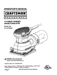
Model No. 831.288283
Serial No.
USER'S MANUAL
|_-i
I |
||
i
|oR
_ |1
H_-LPLINEI
1- 8Q'02736-6
879
-?i.:
".:. SEARS,
_"HOFFMAN
ESTATES, IL 60179
TABLE
OF CONTENTS
IMPO,_T,A!4]I", PB..EC.A,.UTIONS. ......
_E,_TS_i_'_0U
BEGli_....7: ........
_" ";,, .........
7 :: .............
: ........
ASSEMBLY
..: ........................................................................
HOW TO USE THE PROFORM ° 975S .......................................................
HOW TO USE THE PULSE SENSOR
......................................................
MAINTENANCE AND STORAGE ..........................................................
CONDITIONING GUIDELINES ............................................................
PART LIST ...........................................................................
EXPLODED DRAWING .................................................................
ORDERING REPLACEMENT PARTS ................................................
LIMITED WARRANTY ...........................................................
.
...,_
..........
. .....................................
.........
2
3
4
8
11
12
13
14
15
Back Cover
Back Cover
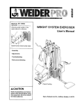
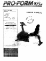
BEFORE YOU BEGIN
Thank you for selecting the innovative PROFORM °
975s. The PROFORM 975s offers a unique form of
low-impact exercise that offers greater cardiovascular
benefits and increased muscle toning. And the 975s
features adjustable resistance so you can tailor your
exercise to the level that's perfect for you.
until 7 p.m. Central Time (excluding holidays). To help
us assist you, please note the product model number
and serial number before calling. The model number
is 831,288283. The serial number can be found on a
decal attached to the 975s (see the front cover of this
manual for the location of the decal).
For your benefit, read this manual carefully before
you use the PROFORM 975s. If you have additional
questions, please call our toll-free HELPLINE at
1-800-736-6879, Monday through Saturday, 7 a.m.
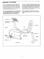
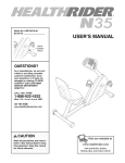
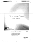
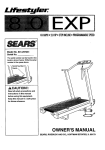
Before reading further, please look at the drawing
below and familiarize yourself with the parts that are
labeled.
Console
_-_
Handlebar with _
Pulse Sensor
;krest
Seat
FRONT
Pedal
Strap --
Seat Handle
Seat Frame
Pedal.
K
LEFT SIDE
ASSEMBLY
Place all parts of the pROFORM" 975s in a cleared area and remove the packing materials. Do not dispose of
the packing materiaJs until assembly Is completed,
Assembly
driver _
requires
the included
.
tools and your own adjustable
wrench
_
and phillips
screw-
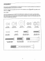
PART CHART
Use the part drawings below to identify the small parts used in assembly. The number in parenthesis below
each drawing refers to the key number of the part. The second number refers to the quantity used in assembly.
Note: Some small parts may have been pre-attached for shipping. If a part is not in the parts bag, check
to see if it has been pre-assembled.
M6 Split
Washer (67)-4
M10 Flat
Washer (71)-4
MIO Split
Washer (26)-3
M4 x 16mm
Screw (34)--1
M6 x 38ram Button
Head Bolt (18)-4
#8 x 5/8"
Screw (22)-4
M6 Nylon
Locknut (66)-4
M6 x 16mm Hex
Head Screw (24)--.4
M10 x 25mm Button
Head Screw (25)-3
M6 x 25mm Hex
Head Screw (14)-4
M10 x 58ram Carriage Bolt (74)-4-
M10 x 105mm Button Head Bolt (70)-4
4
M10 Nylon
Locknut (72)-8
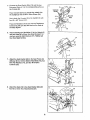
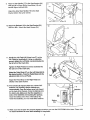
1. Loosenthe LockKnob(68)on therightsideofthe
Frame(1). SlidetheSeatFrame(3)outuntilit
stops.33ghten
the LockKnob.
Identifythe RearStabilizer(73)(therearenowheels
ontheRearStabilizer).
Attachthe RearStabilizerto
theSeatFrame(3)withtwoM1Ox 58mmCarriage
Bolts(74)andtwoM10NylonLocknuts(72).
72
73
2. Identifythe FrontStabilizer(75),whichhaswheels
attachedto it.Attachthe FrontStabilizer(75)tothe
Frame(1)withtwoM10x 58mmCarriageBolts(74)
andtwo M10NylonLocknuts(72).
2
3. Attachthe Upright(2)to the Frame(1)withthree
M10x 25mmButtonHeadScrews(25)andthree
MlO Split Washers (26). Be careful not to pinch
the Reed Switch Wire (13) or the Resistance
Cable (10).
25
26\
25
4. Route both Extension Wires (41) up through the
Uptight (2) as:shown.
4
_14
Attach the Handlebar (4) to the Upright (2) with two
M6 x 25mm Hex Head Screws (14) and two M6 Split
Washers (67), but do not tighten the Screws yeL
Make sure that the Screws are threaded into the
indicated holes. Note: Two additional Screws will
be attached
/
in step 6.
5
67
41
4
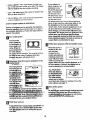
5. Connect the Reed Switch Wire (13) and the two
Extension Wires (41) to the corresponding wires on
the Console (8).
Console
If your Console (8) has a ground wire, attach it to
the Updght (2) with an M4 x 16ram Screw (34).
;
.
Next, attach the Console (8) to the Uprfght (2) with
four #8 x 5/8" Screws (22).
ep
Ground
Wire
10
Press the Resistance Knob (9) onto the Resistance
Control (10). Be sure that the mark on the Knob is
correctly aligned.
6.
Finish attaching the Handlebar (4) to the Upright (2)
with two more M6 x 25ram Hex Head Screws (14)
and two more M6 Split Washers (67). Tighten ell
four Hex Head Screws.
7.
Attach the SeatBracket (69) to the Seat Frame (3)
with f0ur M!0 x 105mm Button Head Bolts (70), four
M10 Flat Washem (7t'), and four M10 Nylon
Locknuts (72).
8.
.,
Attach the Seat (16) to theseat Bracket (69) with
four M6 x 16ram Hex Head Screws.(24).
6;
14
7O
9.
Attach a Seat Handle (17) to the Seat Bracket (69)
with two M6 x 38mm Button Head Bolts (18) and
9
two M6 Nylon Locknuts (66).
Attach the other Seat Handle (17) to the Seat
Bracket (69) in the same manner.
10. Attach the Backrest (15) to the Seat Bracket (69)
with four M6 x 16mm Hex Head Screws (24).
10
11. Identify the Left Pedal (45) (there is an "L" on the
Left Pedal for identification). Using an adjustable
wrench, tighten the Left Pedal counterclockwise into
the left arm of the Crank (29).
"13ghten the Right Pedal (not shown) clockwise into
the dght arm of the Crank (29).
Adjust the Pedal Strap (27) on the Left Pedal (45) to
the desired position. Press the Pedal Strap onto the
adjustment tab on the Left Pedal,
Adjust the Pedal Strap on the Right Pedal (not
shown) in the same manner.
12. The Console (8) requires either two or three "hA"
batteries (not included); alkaline batteries are
recommended. Open the battery cove r (not shown)
on the back of the Console. Press the batteries into
Battedes
the battery clip. Make sure that the negative (-)
ends of the batteries are touching the springs.
Close the battery cover. Note: If the battery clip
holds three batteries, you must insert three batteries.
@
Battery
Clip
13. Make sure that all parts are properly tightened before you use the PROFORM" 975s. Note: There may
be some hardware left over after assembly Is completed.
7
HOW TO USE THE PROFORM ®975S
HOW TO ADJUST THE PEDAL STRAPS
HOW TO ADJUST THE POSITION OF THE SEAT
FRAME
To adjust each Pedal Strap (27), first pull the end of
the Pedal Strap off the adjustment tab on the Pedal
(45). Align a different hole in the Pedal Strap with the
adjustment tab. Press the Pedal Strap onto the
adjustment tab.
The Seat Frame (3) can be adjusted to the position
that is the most comfortable for you. To adjust the
Seat Frame, first loosen the Lock Knob (68) on the
right side of the Frame (1). Slide the Seat Frame forward or backward to the desired position. Tighten the
Lock Knob.
Adjustment
45
HOW TO ADJUST THE PEDALING RESISTANCE
The pedaling
resistance can
be adjusted
with the
Resistance
Knob (9) located on the
Console (8). To
increase the
resistant, tum
,. ........ .......
,
the "Re_si_,ance _b
_;"
to decrease the _i:esistance turn the Resl_ance Knob counterclockwise.
8
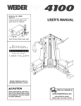
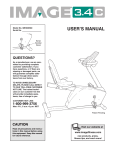
DIAGRAM
OF THE CONSOLE
00000
Manual
00000
0
C.AL
SPeeD
TIMG
t..AP5
DI_E.
ON / R_s_r
PROGRAM
Note: If there is a thin
sheet of clear plastic on
the face of the console,
remove it.
I_WmHIBJWmNNImgll_J_m
DESCRIPTION
OF THE CONSOLE
tots even. Important: The target pace Is a goal
pace. Your actual pace maybe slower than the target pace, especially during the first few mon.ths of
your exercise program. Be sure to exercise at a
pace that is comfortable for you.
The innovative console offers a manual mode and
three pacer programs. The pacer programs am
designed to help you achieve your exercise goals by
pacing your exemlse. The programs include an 18
MPH/90 RPM program, a 12 MPW60 RPM program,
and a 6 MPH/30 RPM program. The console also features liv.e_nonltor modes that provide continuous exercise feedba_-k. Note: On some consoles the programs are listed in MPH and on others in RPM.
Both sets of programs are Identical.
HOW THE PACER PROGRAMS OPERATE
When you use a
pacer program, an
indicato[,Wlll I
on each,track of
the P.A.C_E.R.
display. The outer
track shows a tar-
The graphs on the left side of the console show how
the target pace will change dudrig ea_! program (see
the drawing above).-Each _aph tS d_ed
Iqt.o._ten:
co umns, and each co umr_-_epresents _l/.-.10;0f,
a. rn e.
The ham in each colt_mn shbw what the_talge_pace
will be during that 1/10 of arnlle. F0r:e_.lp_._n
_e
first column of the 12 MPH/60 RPM graph, them Is
one bar. This shows:ithat dudng the first 1/10 oo_a mile
in this program, the targetogaCe will be 6MF?H (80 :,
• :, RPM). In thesecond column, there are tw0. bars, indi'
cating that the,pace is:now :12MI_H (60,BP.M)_.
: "=_::_:r._;_._"_./'_-7_.':-_
_' ,_._r_.'m'
_'_
DESCRIPTION_OFi_E
MONITOR M_DE,S_.
The five monitor modes provide continuous exercise
feedback. The modes are described below.
get pace; the inner
ooo ooo(
track will show
o oo ooo
your actual pace•
The target pace
will change periodically during the 18 MPH/90 RPM
and 12 MPH/60 RPM programs; as the target pace
changes, simply adjust your pace to keep both indica-
• Speed--This
hour.
mode shows your pace, in miles per
• Time--This mode counts the length of time you
have exercised. Note: If you step exercising for ten
seconds or longer, the time mode will pause.
9
• Distance (1)lST}--This mode shows the total number of ml]es you have cycled, up to 999. The display
will then reset to zero and continue counting.
If you selectod a
pacer program, two
indicators on the
P.A.C.E.FL track will
rKjht. The indicator
on the irmer track
will show your actual
pace. The indicator
on the outer track
• Laps--This mode shows the number of quarter-mile
laps you have completed.
• Calories (CAL)--This mode shows the approximate
number of calories you have burned.
STEP-BY-STEP
will move around the track at the programmed
pace. AS you exercise, adjust your pace so that
the indicators on the inner and outer tracks
remain even. As the program progresses, the target pace will change periodically; as the target
pace changes, you should also adjust your pace.
Important: The target pace is a goa/pace. Your
actual pace may be slower than the target
pace, especially during the ;first few months of
your exercise program. Be sure to exercise at
CONSOLE OPERATION
Before the con.._;otacan be operated, the batteries
must be Installed. (See assembly step 12 on page 7
for installation instructions.) Follow the steps below to
operate the conso!e.
HTurn
on the power
To turn on the
a pace that Is comfortable
power, press the
on/reset button or
simply begin exercising. When the
oN / Reset PROGRAM
power is _
on,
the erfue _splay
will appear for two seconds. The console wit( then
• be ready for use. Note: if batteries were just
installed, the power will already be on.
B
L_
When the power is,,
first turned on, the
consola_i
be.in
j
-:,;_-.........
,.........
i......._
M_uat •
I _:=-,,. ,,_•::: ::
]
buifon. =_.
cato T ! ow'ihave_3e'l_L_d..Th d • ...,,.:_._
.
prog_wd!_se
selected_ln the'fblloWlng order:..,
"_-_
u __!L-_a_g_::
the6 MPH/30_3pM
Note: unceyou:so,ect
...-. .... :.,,
;:;
off the
,,..= Turn
program
repeatedly_i_'r#-,;ssingthe.i_m-_Pafii'b[_tdh.l_Jlhegl__Ou_-w_rkout
_To t0_ff,_the,
a pacer
. .:.._;_
: ,:,
.
. _-:.,
I
oi_ .
,
_
. :.:.
If you _selected,_e manual mode, one Indicator on
'PJ,:C:E,R:
power
power,_simp_ly waitlbt,:about
'.co_la_o;_-_ho_re_ed
M
ths
"ld
grip pulse sensor._..- ._ J ....
_.pu_'._-,._ _ [
The pulse display •
allows you to monitor
:,
. :
your heart rate during your workout. To use the
pulse sensor, see page 11.
The I_ogmm:lr_- "
.=t e_
,::,°L:
I
975s also features
-,.an lllnot_veJ1mld ....
:
_-At. tAPS
mode is currently displayed. When the laps mode =s cEspis,
yed, an "1_"
will also appear,-If desired, the d'mplay can be
reset by pressing the on/reset button, .....
i
_- :,,
relief'press"
the pi_('_m
for you.
Follow your progress with the monitor modes
When the power is
turned on, the console will scan
through the five
modes automatically.
A flashing mode indicator wig show which
Selact_ne of the three pacer programs or the
mai_bal:inode_:"
'
"
:" :: " "
"the __.
O
'-
cise,:_
_icator'will
:mo_,e:ardUndt_e'quartermile ti'T_ _ " "' ': . .......
_;"-:' - "' "'
10
six,
for six minutes,
,..
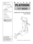
HOW TO USE THE PULSE SENSOR
The convenient pulse sensor allows you to measure
your hear rate periodically. You can measure your
head rate before you begin exercising, during your
workout, and again when you finish.
ly, the hear indicator w!Uflash repeatedly in the
PULSE display but your hear rate will not be shown.
If an "L" appears in the PULSE display, then the
pulse sensor received too little pulse information to
accurately calculate your pulse. Let go of the metal
contacts; then place your hands on the contacts
again. Your palms must be resting on the inner contacts and your fingers must be touching the outer
contacts,
Note: Before
you can use
the pulse sensor, you must
peel the protective vinyl covering off the
metal contacts
on the front
end rear
__...y / \
\
• If an "H" appears in the PULSE display, then the
pulse sensor received too much pulse information to
accurately calculate your pulse. Let go of the metal
contacts; then place your hands on the contacts
again. Your palms must be resting on the inner contacts and your fingers must be touching the outer
contacts.
Contacts
of each pulse
grip.
To use the pulse sensor, fimt make sure that the power
is turned on. Stop exercising, rest both feet on the
floor, and place your hands on the _netal contacts. Your
palms must be resting on the inner contacts and your
fingers must be touching the outer contacts. Avoid
moving your hands. After a moment, the heart indicator
in the PULSE display will flash and your hear rate will
be shown. For the most accurate hear rate reading,
continue to hold the contacts for about 15 seconds.
• Do not hold the metal contacts too tightly; doing so
may interfere with head rate readings.
Do not move your hands while you hold the metal
contacts; your muscle movement may interfere with
hear rate readings.
For the most accurate heart rate reading, wait for
about 15 seconds.
HAND PULSE SENSOR TROUBLE-SHOOTING
For optimal performance of the pulse sensor, keep
the metal contacts clean. The contacts can be
cleaned with a soft clo_ever
use alcohol,
abrasives, or chemicals.
• Avoid moving your hands while using the pulse sensor. Excessive movement may interfere with hear
rate readings. If the pulse sensor is not used correct-
11
MAINTENANCE
AND STORAGE
Inspect and tighten an parts of the PROFOFIM _ 975s
regularly. The 975s can be cleaned with a soft, damp
cloth. To prevent damage to the conso(e, keep liquids
away and keep the console out of direct sunlight.
in one of the slots in the slotted bearing nut. Ughtly
tap the screwdriver with a hammer to turn the slotted
bearing nut counterclockwise until the arms are _;)
longer loose. Do not overtighten the slotted bearing nuL When the slotted bearing nut is properly
tightened, tighten the crank nut.
BA'I-rERY REPLACEMENT
If the console does not function propedy, the batteries
should be replaced. To replace the batten'es, refer to
assembly step 12 on page 7.
HOW TO STORE THE PROFORIVP 975S
When the PROFORfVP975s is
not in use, it can
be folded for
CRANK ADJUSTMENT
If the arms of the
Crank (29)
become loose,
theyshould be
tightened in
order to prevent
excessive wear,
Loosen the
crank nut on the
left arm of the
Crank. Place the
end of a standard scrawddver
compact storage.
Refer to the
drawing at the
n'ght. Loosen the
Lock Knob (68)
on the right side
of the Frame (1).
Slide the Seat
Frame (3) as far
fnto the Frame
as it will go. "lighten the Lcok Knob. Store the PROFOFtM_975s _ndoors, away from_mofstu_.e and dust.
12
CONDITIONING
GUIDELINES
The following guidelines will help you to plan your
exercise program. Remember that proper nutrition and
adequate rest are essential for successful results.
WHY EXERCISE?
Exercise has proven essential for good health and
general weU-being. Regular participation in a wellrounded exerc_e program results in a stronger and
more efficient heart, improved respiratory function,
increased stamina and endurance, better weight management and body fat control, increased ability to deal
with stress, and greater self-esteem and confidence.
EXERCISE
During the first few months of your exercise program,
keep your heart rate near the low end of your_training
zone as you exercise. After a few months of regular
exercise, your heart rate can be increased gradually
until it is near the middle of your training zone as you
exercise.
To measure your heart rate, use the pulse sensor in
the handlebar. You can also measure your pulse by
placing two fingers
on your wrist. Stop
exercising and
take a six-second
heartbeat count.
Multiply the result
by ten to find your
heart rate. (A sixsecond count is
used because
your heart rate
drops quickly
when you stop
exercising.) If your heart rate is too high, decrease the
intensity of your exercise. If your heart rate is too low,
increase the intensity of your exercise.
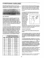
INTENSITY
To maximize the benefits of exercising, it is important
to exercise with the proper !ntensity. The proper intensity level can be found by using your heart rate as a
guide. For effective aerobic exercise, your heart rate
should be maintained at e level between 70% and
WORKOUT
A well-rounded
phases:
85% of your maximum heart ate as you exercise.
This is known as your training zone. You can find
your training zone In the table below. Training zones
are listed according to age and physical condition.
UNCONDITIONEI3
CONDmONED
20
138-167
133-162
25
136-166
132-160
30
135-164
130-158
35
134-162
129-156
40
132-161
127-155
45
131-159
125-153
50
129-156
124-150
55
127-155
122-149
60
126-153
121-147
65
125-151
119-145
70
123-150
118-144
75
122-147
117-142
80
120-146
115-140
85
118-144
114--139
workout includes the following three
A warm-up phase, lasting 5 to 10 minutes. Begin with
slow, controlled stretches, and progress to more rhythmic stretches. This will increase the body temperature,
heart rate, and circulation in preparation for strenuous
exercise.
TRAINING ZONE (BEATS/MIN.)
AGE
GUIDELINES
A cardiovascular phase, including 20 to 30 minutes
of exercising with your heart rate in your training zone.
A cool-down phase, consisting of 5 to 10 minutes of
stretching. Thorough stretching offsets muscle contractions and other problems caused when you stop
exercisingsuddenly. Stretching for increased flexibi ity
• is.ofteri m0s_._ffe_'e:;during this phase;,This phase"
_ll_Li!d Iba_;e _,bL_relaxed-and comfortabiy tired.
To maintain or improve your condition, complete three
workouts each week, with at least one day of rest
between workouts. After a few months of regular exercise, you may complete up to five workouts each
week, if desired. Find the best time of day for your
workouts, and then stick with it.
Remember, the key to success is to make exercise a
regular and enjoyable part of your everyday life.
13
PART LIST---Model
Key No.
1
2
3
4
5
6
7
8
9
10
11
12
13
"14
15
16
17
18
19
20
21
22
23
24
25
26
27
28
29
30
31
32
33
34
35
36
37
38
39
No. 831.288283
R0899A
Qty.
Description
1
1
1
1
2
1
1
1
1
1
4
4
1
4
1
1
2
4
2
1
6
21
2
8
3
3
1
1
1
1
1
1
2
1
4
2
2
2
4
Frame
Upright
Seat Frame
Handlebar
Pulse Grip
Left Side Shield
40
41
42
43
44
45
2
2
1
1
1
1
M10 Washer
Extension Wire
Flywheel
10mm x 13mm Spacer
Flywheel Axle
Left Pedal
Right Side Shield
Console
46
47
2
2
M10 x 52ram Button Head Screw
Wheel
Resistance Knob
Resistance Cable/Control
M5 x 30mm Screw
M5 Nut
Reed Switch/Wire
M6 x 25ram Hex Head Screw
48
49
50
5!
52
53
5
1
1
1
2
4
2" x 3" Endcap
1 1/2" x 3" Endcap
Cable Clamp
M6 x 56mm Bolt
M8 Split Washer
#8 Fiat Washer
Backrest
Seat
Seat Handle
M6 x 88ram Button Head Bolt
Foam Handle Grip
1" x 3" Endcap
Tree Fastener
#8 x 5/8" Screw
54
55
56
57
58
59
60
61
1
1
1
1
1
1
1
1
Clamp Bolt
Clamp Nut
Resistance Hook
Resistance Spring
Magnet Bracket
M8 x 65ram Hex Head Bolt
M8 Nylon Locknut
Ddve Belt
#8 x 3/8" Screw
M6 x 16mm Hex Head Screw
M10 x 25mm Button Head Screw
M10 Split Washer
Left Pedal Strap
Right Pedal
Crank/Pulley
Beadng Assembly
Right Pedal Strap
Magnet : :.;"
"
62
63
64
65
66
67
68
69
70
71
2
1
1
1
4
4
1
1
4
4
1 1/4" RoundlEndcap
2" x 4" Endcap
Frame Bushing
Seat Frame Bushing
M6 Nylon Locknut
M6 Split Washer
Lock Knob
Seat Bracket
M10 x 105ram Button Head Bolt
M10 Flat Washer
M4 x 32mm Screw
M4 x 16ram Screw
72
73
10
1
M10 NyJgn Locknut
Rear Stabilizer
Rubber Bumper
M8 Ranged Hex Nut
M6 Eyebolt
Adjustment Bracket
M6 Nut "
74
75
#
#
#
4
1
1
1
1
MIO x 58mm Carriage Bolt
Front Stabilizer
User's Manual
4rnm Alien Wrench
5.5ram Allen Wrench
Key No.
Qty.
Description
Note_."#':, nd:_:,,cates,
a.,non-. ustra{ed,
_ part --.Specif cat ons are sub'ectj to chanae without notice. See the back cover
of th_s manual for Informatio_about
Ordering replacement parts
14
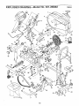
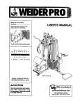
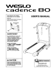
EXPLODED
DRAWING--Model
No. 831.288283
R0899A
21
22
22
25
26
72
47
46
72
39
t
_s
48
70
74
24
29
63
22
39
48
16
73\
22.-_1
17
18
15
The model number and serial number of your PROFORM • 975s
Model No. 831.288283
are listed on a decal attached to the frame. See the front cover
this manual to find the location of the decal.
.c, --
QUESTIONS?
All replacement parts are availab[e for immediate purchase or
special order when you visit your nearest SEARS Service Center.
To request service or to order parts by telephone, call the toll-free
numbers listed at the left.
If you find that:
• you need help assembling or
operating the PROFORM" 975s
When requesting help or service, or ordering parts, please be prepared to provide the following information:
• a part is missing
• or you need to schedule repair
service
• The MODEL NUMBER
of the product (831.288283).
• The NAME of the product (PROFORM"
975s).
call our toll-free HELPLINE
• The KEY NUMBER and DESCRIPTI@N of the PART (see the
PART LIST and the EXPLODED DRAWING on pages 14 and 15).
1-800-736-6879
Monday-Saturday, 7 am-7 pm
Central Time (excluding holidays)
REPLACEMENT
PARTS
.i ¸
.
If pa.rts'l:_come worn and need to
be,i:eplaced; c@ll the following tollfree numloer
1-800-FON-PART
r, ;
(}1,800.-866-7278)
I
FULL 90 DAY WARRANTY
._For 90 days from the date of purchase If failure _occurs due to defect n matenal or workmanship in th s
-,.,SEARS B KE EXERC SER contact the nearsst SEARS Serv=ce Center throughout the Un ted States
>ar_€i sEA'Rs f_tlilre_pair or"_eplac_ {h'e BIkE,'EXEB-CISi=R, free of Charge.. :
:l'his warranty does not apply when the BIKE EXERCISER is used commercially or for rental purposes.
This warranty gives you specific Iegaf dghts, and you may also have other dghts which vary from state
-';_,tdstate."_
_ _ ,
.
..
... ..
SfZARS-;.ROEBUCK AND CO., DEPT. 817WA, HOFFMAN
Part No. 159040 R0899A
ESTATES,
IL 60179
Printed in China © 1999 Sears, Roebuck and Co.