1
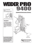
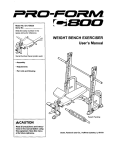
ModelNo.831.153931
SerialNo.
Writetheserialnumberinthe
spaceaboveforreference.
USER'S MANUAL
SerialNumberDecal(underseat)
EXERCI-_E
E(_
ioigI
U
I
PM
=I,._
I
E
IOI
NT
_ I,;
HELPLINE!
!-800-736-6879
Patent Pending
SEARS, ROEBUCK AND CO.
HOFFMAN ESTATES, IL 60179
_CAUTION
Read all precautions and instruc.
lions in this manual before using
this equipment. Save this manual
for future reference.
._-'Vis_our
website
at_
www.weiderfitness.com
new products, prizes,
fitness tips, and much more!
TABLE OF CONTENTS
IMPORTANT PRECAUTIONS .............................................................
BEFORE YOU BEGIN ...................................................................
ASSEMBLY ...........................................................................
ADJUSTMENTS .......................................................................
WEIGHT RESISTANCE CHART ...........................................................
TROUBLESHOOTING ..................................................................
CABLE DIAGRAMS ....................................................................
ORDERING REPLACEMENT PARTS ................................................
FULL 90 DAY WARRANTY .......................................................
3
4
5
22
24
25
26
Back Cover
Back Cover
Note: A PART IDENTIFICATION CHART and a PART LIST/EXPLODED DRAWING are attached in the center of
this manual. Remove the PART IDENTIFICATION CHART and the PART LIST/EXPLODED DRAWING before
beginning assembly.
2
IMPORTANT
PRECAUTIONS
_WARNING:
To .d.=.
before using the Weight system.
th. risk of serious infury, mad the following Important precautions
1.
Read oil inatructio_s In this manual and in
the au:ompanying IItondure before using the
weight system.
13, Always dlsconnect b'm lat bar from the
weight system when performing an exercise
_at does not use the/at bar.
2.
It is the responsibility of the owner to ensure
that all users of the might system m adequately Informed of all precautions,
14. Make sure that the cables remain on the pulisys at all tim_
If the cables bind whlis you
are exercising, stop immedlateiy and make
sure that the cables m on all of the pulleys.
3.
The weight system is intended for home use
only. Do not use the welg_ system in any
commercial, rental, or instib_onal ea_itng.
4.
Use the weight system only on a level =mr.
face. Cover the floor beneath the weight system to prntect the Itoor.
5. Make sure that all parts are properly tightened each time you use the weight system.
Replace any wom parts Imm_
6.
Keap childmn under 12 and pats away from
the weight system at all time&
7.
Ksep hands and feat away from moving parts.
8.
Always wear athletic shoes for foot protecllon;
9.
Tbe weight syatem is dexlgned to support a
a maximum user weight of 300 pounds.
10. The weight syatm should not be used by
more than one person at a time.
11. Always stand on the foof plato when per.
forming an exercise that could cause the
weight system to tip.
r
ING:
Before beginning
%
=
15.Thewarningdecalssimwnhemhavebeen
placed on the weight system in the locations
shown on page 4. if a decal Is mimdng or
illegible, plemm call our toil-free HELPLINE at
' 1-800-736-6879, Monday through Sabaday,
7 a.m._untit 7 p.m, C4mbal Time, to order a
frea mptacement dacaL Place the de_d on
the walght syatsm in the location shown.
• Misuseofthisproduct
may result,nserious
injury
• Readuser'smanual
andfollow allwarnings
andoperatingmstruchonspriorto use.
• Do notallowchildren
onor aroundmachine.
• Replacelabelif
damaged,illegible,or
removed.
12. Never mime the butterfly arms, leg lever,
squat arm, lat bar, row bar, or handis while
weights am raised. The weights will fail with
grset force.
AWARN
,
15. If you feel pain or dizzJness at =my time while
exercising; stop Immediately and begin cooling down.
thls or sny exercise
Decal 2
Decal 1
program, consult your physician. This
Is especially Important for parsons over the ago of 35 or persons with pre-existing health proMems,
Read all instructions before using. SEARS assumes no responsibility for personal Injury or property
damage sustained by or through the use of this product.
BEFORE YOU BEGIN
Thank you for selecting the versatile WELDER®PRO
4850 weight system. The WELDER®PRO 4850 weight
system offers an impressive array of weight stations
designed to develop every major muscle group of the
body. Whether your goal is to tone your body, build
dramatic muscle size and strength, or improve your
cardiovascularsystem, the PRO 4850 weight system
will help you to achieve the specificresults you want.
1-800-736-6879, Monday through Saturday, 7 a.m.
until 7 p.m. Central Time (excluding holidays).To help
us assist you, please note the productmodel number
and sedal number before calling. The model number is
831.153931. The serial number can be found on a
decal attached to the weight system (see the front
cover of this manual for the location of the decal).
Before reading further, please review the drawing
below and familiarize yourself with the parts that are
labeled.
For your benefit, read this manual carefully before
using the weight system. If you have additional
questions, please call our toll-free HELPLINE at
WARNING
DECAL t
ASSEMBLED
DIMENSIONS:
Height: 81 in.
Width: 96 in.
Length: 57 in.
Lat Ba_
High Pulley Station
Swivel Carriage
WARNING DECAL 2
(one on each side)
Butterfly
Backrest
Low Pulley Station
Squat Arm
Backrest
Cud Pad
.AdjustmentKnob
Seat
WARNING
DECAL2
Leg Level
uat Knee Rest
Weight Stack
4
ASSEMBLY
Make sure that you have the following tools:
Make Assembly Easier
• Two adjustablewrenches
Evewthing in this manual is designed to
ensure that the weight system can be assembled successfully by artjone.
• One standard scrawddver
• One philhpsscrewdriver
Before beginning assembly, makoosure to
read the information on this page. This
brief Introduction will me you much more
time than It takeS to read it.
• One rubber mallet
• You w=llalso need grease or petroleumjelly, a
small amount of soapy water, and masking tape
Note: Assembly will be more convenient if you have
a socket set, a set of open-end or closed-end
wrenches, or a set of ratchet wrenches.
Assembly Requires Two Persons
For your convenience and safety, assemble the
weight system with the help of another person.
How to Identify Parts
Set Aside
Enough
Time
To help you identify the small parts used in assembly,
a PART IDENTIFICATION CHART is included in the
center of this manual. Lay the chart on the floor and
use it to easily identify parts dudng each assembly
step. Note: Some small parts may have been preattached. If a part is not in the parts bag, check
to see if it has been pre-attached.
Due to the many features of the weight system, the
assembly process will require several hours. By
setting aside plenty of time and by deciding to
make the task enjoyable, assembly will go smoothly.
Select a Location for the Weight System
Because of _tsweight and size, the weight system
should be assembled in the locationwhere it wdl be
used. Make sure that there is enough room to walk
around the weight system as you assemble it.
How to Orient Parts
As you assemble the weight system, make sure that
all parts are oriented exactly as shown in the drawrags.
How to Unpack the Box
Tightening Parts
To make assembly easier, we have divided the
assembly process into four stages. The small hardware needed for each stage is packaged in separate bags. Important: Wait until you begin each
stage to open the parts bag(s) for that stage.
Place all parts of the weight system in a cleared
area and remove the packing materials. Do not dispose of the packing matarials untJIassembly is completed
Tighten all parts as you assemble them, unless
instructedto do otherwise.
Questions?
If you have questionsafter reading the assembly
instructions,please call our Customer Service
Department toll-free at 1-800-736-6879, Monday
through Fdday, 6 a.m. until 6 p.m. Mountain Time.
The Four Stages of the Assembly Process
Frame Assembly--You will begin by assembling
the base and the updghtsthat form the skeleton of
the weight system
Cable Assembly--Dudng this stage, you will
attach the cables and pulleys that connect the
weight stationsto the weight stacks.
Arm Assembly--Dunng this stage, you will
assemble the arms and the leg lever.
Seat Assembly--Dudng the final stage, you will
assemble the seat and the backrests.
5
FRAME ASSEMBLY
I
1.
Make sure that you unde_mnd a|! of the
infonmdion on page 5 before you begin
assembling the weight system.
71
85
120
Locate and open the parts bags labeled "FRAME
ASSEMBLY 1" and "FRAME ASSEMBLY 2."
86
Press a 2" Square Inner Cap (105) into the open
end of the Long Base (120).
110
110
Insert eight 5/16" x 2 112"Carriage Bolts(110) up
through the Long Base (120) and the Short Base (2)
as shown. Note: It may be helpful to place tape
over the heads of the Carriage Bolts to hold
them in place.
110
110
Attach the Short Base (2) to the Long Base (120)
with two 5/16" x 2 3/4" Bolts (85), the Long Frame
Plate (71), and two 5116"Nylon Locknuts(86).
120
58
2.
86
Attach the Outer Cap (24) to the Short Base (2)
with two #8 x 314"Screws (98).
Press two 2" x 3" Inner Caps (58) into the Foot
Plate (53). Attach the Foot Plate to the Long Base
(120) with two 5/16" x 2 112"Carnage Bolts (110)
and two 5/16" Nylon Locknuts (86)
3.
1
24
Attach the tether on the Pin (112) to the Long Base
(120) with a #10 x 1" Screw (14).
3
Attach the four Knee Rest Bumpers (123) to the
Squat Knee Rest (41) with four #10 x 1" Bcrews
(14) Attach the Squat Knee Rest to the Long Base
(120) with a 3/8" x 3 1/4" Bolt (96) and a 3/8" Nylon
Locknut (87) Do not overtightan the Nylon
Locknut; the Squat Knee Rest must be able to
pivot.
41
6
4.
Press a 1 1/2" Square Inner Cap (67) into the
square tube on the ButterflyUpright (3).
Slide the ButterflyUpright (3) onto the two indicated
5/16" x 2 1/2" Carriage Bolts(110) in the Short Base
(2). Finger tighten a 5/16" Nylon Locknut (86) onto
each Cardage Bolt. Do not tighten the Nylon
Locknuts yet.
5.
Press a 2" x 3" Inner Cap (58) into the top of the
Seat Upright (9). Attach the Leg Lever Bumper (77)
to the Seat Upright with a #10 x 1" Screw (14).
5
58
77,
Slide the Seat Upright (9) onto the two indicated
5/16" x 2 1/2" Carriage Bolts (110) in the Short
Base (2). Finger tighten a 5/16" Nylon Locknut (86)
onto each Carriage Bolt. Do not tighten the Nylon
Locknuts yet.
14
110
6.
Hold the Seat Frame (8) between the Seat Upright
(9) and the Butterfly Upright (3). Attach the Seat
Frame to the Seat Upright with two 5/16" x 3 3/4"
Bolts (92), two 5/16" Washers (90), and two 5/16"
Nylon Locknuts (86). Do not tighten the Nylon
Locknuts yet.
Attach the Seat Frame (8) to the Butterfly Upright
(3) with two 5/16" x 3 3/4" Bolts (92), two 5116"
Washers (90), and two 5/16" Nylon Locknuts (86).
Do not tighten the Nylon Locknuts yet.
7
7,
Press a 2" x 3" Inner Cap (58) into the top of the
Squat Upright (4). Slide the Squat Upright onto the
two indicated 5/16" x 2 1/2" Carriage Bolts (110) in
the Long Base (120). Finger tighten a 5/16" Nylon
Locknut (86) onto each Carriage Bolt. Do not tighten the Nylon Locknuts yet,
58
Press a 2" x 3" Inner Cap (58) into the top of the
Swivel Upright (5). Slide the Swivel Updght onto the
two indicated 5/16" x 2 1/2" Cardage Bolts(110) in
the Long Base (120). Finger tighten a 5/16" Nylon
Locknut (86) onto each Carriage Bolt. Do not tighten the Nylon Locknuts yet.
86
120
8.
Press two Swivel Bushings (66) into the Swivel
Carriage (46).
8
66
Tighten an Adjustment Handle (65) into the Swivel
Carriage (46). Orient the Swivel Carriage as shown.
Slide the Carriage onto the Swivel Upright (5) and
engage the Adjustment Handle into an adjustment
hole in the Swivel Upright.
65 ¸
?
Adjustment
Hole "_.
8
9.
Attach a Roller (39) and two 5/16" Washers (90)
between the indicated set of holes in the Squat
Slider (38) with a 5/16" x 3 112"Bolt (94), two 5/16"
Washers (90), and a 5/16" Nylon Locknut (86) as
shown.
39
3
Assemble the other three Rollers (39) to the
Squat Slider (38) in the same manner,
90---_r_39
10. Slide the Squat Slider (38) down onto the Squat
Updght (4).
10
11. Insertthe ends of two Weight Guides (42) intothe
indicatedbracket on the Long Base (120). Slide two
Weight Bumpers (49) ontothe Weight Guides. Next,
slideten Weights (44) ontothe Weight Guides. Make
sure that the Weights are turned so the grooved
sides of the Weights are facing downward,
Press a Weight Tube Bumper (48) into the lower
end of a Weight Tube (43). Insert the Weight Tube
into the centers of the Weights (44). Make sure
that the Weight Tube is turned as shown.
Lubricate the two outer holes in a Top Weight (45).
Slide the Top Weight onto the Weight Guides (42).
Make sure that the Top Weight is turned so the
grooved side is facing downward.
Apply a number "10" decal to the Top Weight (45) in
the locationshown. Apply decals with the numbers
20 through 110 to the ten Weights (44).
Assemble
way,
the other weight stack in the same
9
.-
6
12. Attach the Top Frame (6) between the Squat Upright
(4) and the Swivel Upright (5) with four 8/16" x 3 3/4"
Bolts (92), the two Short Frame Plates (52), and two
5116"Nylon Locknuts (86) as shown. Do not tighten
the Bolts and Locknuts yet.
12
Attach the four Weight Guides (42) to the Top Frame
(6) with two 3/8" x 6 112"Bolts (95) and two 318"
Nylon Locknuts(87).
r//
52
_L_
13. Press two 2" x 3" Inner Caps (58) into the Top Frame
(6) and the ButterflyTop Frame (7).
9_
_'_g2
13
92____9
Attach the Butterfly Top Frame (7) to the Top Frame
(6) with two 5/16" x 2 314"Bolts (85), two 5/16"
Washers (90), and two 5/16" Nylon Locknuts (86).
Do not tighten the Locknute yet.
o
58
86<
85
Attach the ButterflyTop Frame (7) to the Butterfly
Upright (3) with two 5/16" x 3 3/4" Bolts (92), two
5/16" Washers (90), and two 5/16" Nylon Locknuts
(86).
58
Tighten all of the 5/16" Nylon Locknuts (86) and
3/8" Nylon Locknuts (87) used in steps 2-13.
14
87
21
14. Open the parts bag labeled "ARM ASSEMBLY."
21
Press three 1 112"x 2" Inner Caps (21) into the Leg
Lever (10). Attach the Eyebolt (116) to the Leg
Lever with a 318"Washer (91) and a 3/8" Nylon
Jamnut (113).
Lubricatea 3/8" x 2 1/2" Bolt (18) with grease. Turn
the Leg Lever (10) so that the welded tab is on the
indicated side, and attach the Leg Lever to the Seat
Upright (9) with the Bolt and a 318"Nylon Locknut
(87). Do not overtighten the Nylon Locknut; the
Leg Lever must be able to pivot easily.
15. Press a 2" x 2 1/2" Inner Cap (125) into the
Butterfly Frame (47). Attach the tethers on the two
"L"-pins w/Tether (60) to the ButterflyFrame with a
#8 x 3/4" Screw (98).
Lubricate a 3/8" x 3" Bolt (107) with grease. Attach
the Butterfly Frame (47) to the ButterflyTop Frame
(7) with the Bolt and a 3/8" Nylon Locknut (87). Do
not overtighten the Nylon Locknut; the Butterfly
Frame must be able to pivot easily.
10
116
21
15
16 Press a 1 112"x 2" Inner Cap (21) intothe Right
ButterflyArm (26) Wet the lower end of the Arm with
soapy water Slide a Long Pad (54) onto the Arm.
16
Slide two Nut Clips (108) onto a Press Handle (27).
Attach the Press Handle to the RmghtButterflyArm
(26) with two 5/16" x 3/4" Button Head Screws (51)
Slide the Long Pad (54) down so that the bottomms
flushwith the lowerend of the Arm. Press a 1"
Round Inner Cap (29) intothe Press Handle Wet
the Press Handle with soapy water Slide a Long
Handgnp (28) onto the Press Handle.
Lubricate a 3/8" x 2" Bolt (100) with grease Attach
a Pivot Bracket (70) to the Right ButterflyArm (26)
with the Bolt and a 3/8" Nylon Jamnut (113). Do not
overtighten the Nylon Jamnut; the Pivot Bracket
must be able to pivot easily. Repeat this step
with the Left Butterfly Arm (25).
17. Lubncate a 3/8" x 3" Button Head Bolt (104) and
both s=desof two Plastic Washers (56) with grease.
Attach the Right ButterflyArm (26) to the Butterfly
Frame (47) with the Bolt, the two Plastic Washers,
two Butterfly Caps (57), two 3/8" Washers (91), and
a 3/8" Nylon Jamnut (113) as shown. Make sure
that the recessed sides of the Plastic Washers
are fitted over the welded bushing in the
Butterfly Arm. Do not overtighten the Nylon
Jarnnut; the Butterfly Arm must be able to pivot
17
26
56
\
57_
91J
113
easily.
Repeat this step with the Left Butterfly Arm (25).
CABLE ASSEMBLY
18
104
IMPORTANT: Refer to the Cable IdentiflcstJon
Chart on page 26 for help Identifying the
cables. Do not overtl_
the belts and
nuts attaching the pulleys. The pulleys must
be able to turn freely.
18
Locate and open the parts bags labeled "CABLE
ASSEMBLY" and "PULLEYS."
Lubncate the 3/8" x 7" Bolt (30) with grease. Attach
the Swivel Cage (76) to the Swivel Carnage (46)
with the Boltand a 3/8" Nylon Locknut (87).
Locate the Swivel High Cable (74), which is 126
112" long and has a ball on one end and a
threaded bolt on the other end. Wrap the Cable
around a 3 1/2" Pulley (78) Attach two Pulleys to
the Swwel Cage (76) wrothtwo 318"x 1 3/4" Bolts
(93) and two 3/8" Nylon Locknuts (87).
11
/ 25
19. Route the Swivel High Cable (74) through the Swivel
Upright(5) and over a 4 1/2" Pulley(119). Attachthe
Pulley insidethe Uprightwith a 3/8" x 2 3/4" Bolt
(101), two 3/8" Washers (91), two 1/2" Spacers (89),
and a 3/8" Nylon Locknut (87).
19
5
91 18
91 "_
91---._ _
Attach a 3/8" x 2 1/2" Bolt (18), two 3/8" Washers
(91), and a 3/8" Nylon Locknut (87) to the Swivel
Upright(5).
.__01
1./l g 74
20. Remove the preattached 3 112" Pulleys (78) from
the Small Pulley Plates (31).
20
Wrap the Swivel High Cable (74) over a 3 1/2"
Pulley (78). Attach the Pulley and a Cable Trap (68)
to the second set of holes from the top of the Small
Pulley Plates (31) with a 3/8" x 2" Bolt (100) and a
3/8" Nylon Locknut (87). Make sure the Cable
Trap is turned to hold the Cable In the groove of
the Pulley.
21. Wrap the Swivel High Cable (74) over a 4 1/2"
Pulley (119). Attach the Pulley inside of the indicated bracket on the Top Frame (6) with 3/8" x 1 3/4"
Bolt (93) and a 3/8" Nylon Locknut (87).
31
31
21
119
22. Lift the Weight Tube (43) and the Top Weight (45)
closest to the Swivel Upright (5). Make sure that the
small pin on the Weight Tube is inside of the groove
under the Top Weight.
22
118
Insert a Weight Pin (50) into the stack of Weights
(44). Place a 1/2" Washer (1) on top of the Weight
Tube (43). "13ghtena 1/2" Nut (118) halfway onto the
end of the Swivel High Cable (74). Screw the end of
the Cable two full turnsinto the Weight Tube. Then,
tightenthe Nut againstthe 1/2"Washer.
23. Locate the Swivel Cable (17), which is 115 318"
long and has an eyelet on each end. Attach the
Cable inside the Top Frame (6) with a 5/16" x 2 1/2"
Bolt (59), two 5/16" Washers (90), and a 5/16"
Nylon Locknut (86).
12
74
50
44
23
59
90 86
,,17
24. Remove the preattached 3 112" Pulleys (78) from
the Offset Double "U"-bracket (61).
24
Wrap the Swivel Cable (17) around a 3 1/2" Pulley
(78). Attach the Pulley to the Offset Double "U"bracket (61) with a 3/8" x 1 3/4" Bolt (93) and a 3/8"
Nylon Locknut (87).
25. Wrap the Swivel Cable (17) around a 3 1/2" Pulley
(78). Attach the Pulley and a Cable Trap (68) to the
next to bottom hole in the Small Pulley Plates (31)
with a 3/8" x 2" Bolt (100) and a 3/8" Nylon Locknut
(87). Make sure the Cable Trap Is tumed to hold
the Cable in the groove of the Pulley.
25
26. Wrap the Swivel Cable (17) around a 3 1/2" Pulley
(78). Attach the Pulley and a Cable Trap (68) to the
bracket on the Swivel Upright (5) with a 3/8" x 2"
Bolt (100) and a 3/8" Nylon Locknut (87). Make
sure the Cable Trap Is turned to hold the Cable
in the groove of the Pulley.
26
27. Attach the end of the Swivel Cable (17) to the
bracket on the Swivel Carnage (46) with a 318"x 1"
Bolt (13) and a 3/8" Nylon Locknut (87).
27
28. Locate the Lat Cable (88), which is 89 1/4" long
and has a ball on one end and an eyelet on the
other. Route the eyelet end of the Cable up through
the ButterflyTop Frame (7) and around a 3 1/2"
Pulley (78). Attach the Pulleyinside of the Butterfly
Top Frame with a 3/8" x 2 3/4" Bolt (101), two 3/8"
Washers (91), two 1/2" Spacers (89), and a 3/8"
Nylon Locknut(87).
28
13
87--._
87
29. Wrap the Lat Cable (88) around a 3 1/2" Pulley
(78). Attach the Pulley and a Long Cable Trap (102)
to the Top Frame (6) with a 318"x 1 3/4" Bolt(93)
and a 3/8" Nylon Jamnut (113). Make sure the
Cable Trap Is turned to hold the Cable In the
groove of the Pulley.
29
102
30. Remove the preattached 3 112" Pulleys (78) from
the Pulley Plates (63).
Wrap the Lat Cable (88) around a 3 1/2" Pulley
(78). Attach the Pulley and a Cable Trap (68) to the
second set of holes from the top of the Pulley
Plates (63) with a 3/8" x 2" Bolt (100) and a 3/8"
Nylon Locknut (87). Make sure the Cable Trap is
turned to hold the Cable in the groove of the
Pulley.
31. Attach the end of the Lat Cable (88) inside of the
ButterflyTop Frame (7) with a 5/16" x 2 1/2" Bolt
(59), two 5/16" Washers (90), and a 5/16" Nylon
Locknut (86).
31
86-.=,_
90
90
4
I
I
32. Locate the Butterfly Cable (69), which is the
shortest Cable, Attach the Cable to the Pivot
Bracket (70) on the Left ButterflyArm (25) with a
5/16" x 1" Shoulder Bolt (103) and a 5/16" Nylon
Locknut (86).
86
[
];_'_-_.70
103
_ /'/IIi A\\E -25
33. Wrap the Butterfly Cable (69) over a "V"-pulley(55).
Attach the Pulley and a Long Cable Trap (102) to
the indicated bracket on the Butterfly Upright (3)
with a 3/8" x 2 1/2" Bolt (18) and a 3/8" Nylon
Locknut (87). Make sure that the Long Cable
Trap is turned to hold the Cable In the groove of
the Pulley.
102
14
34. Remove the preattached 3 1/2" Pulleys (78) from
the Double "U"-brackst (62).
Wrap the Butterfly Cable (69) under a 3 1/2" Pulley
(78). Attach the Pulley to the Double "U"-bracket
(62) with a 3/8" x 1 3/4" Bolt (93) and a 3/8" Nylon
Locknut (87).
35. Wrap the Butterfly Cable (69) over a =_r'-pulley (55).
Attach the Pulley and a Long Cable Trap (102) to
the other bracket on the Butterfly Upright (3) with a
3/8" x 2 1/2" Bolt (18) and a 3/8" Nylon Locknut
(87). Make sure that the Long Cable Trap is
turned to hold the Cable in the groove of the
Pulley.
35
36. Attach the Butterfly Cable (69) to the Pivot Bracket
(70) on the Right ButterflyArm (26) with a 5/16" x 1"
Shoulder Bolt (103) and a 5/16" Nylon Locknut (86).
36
37. Locate the Lag Lever Cable (75), which is 98 1/2"
long and has an eyelet on one end and a threaded pin on the other end. Route the eyelet end of
the Cable through the Seat Upright (9) and attach it
to the tab on the Leg Lever (10) with a 5/16" x 1"
Shoulder Bolt (103) and a 5/16" Nylon Locknut (66).
37
86
//
Y
103
38. Attach a 3 112"Pulley (78) inside of the Seat
Upright (9) with a 3/8" x 2 3/4" Bolt (101), two 3/8"
Washers (91), two 112"Spacers (89), and a 3/8"
Nylon Locknut (87), as shown.
38
91
101
89
15
J
39. Route the Leg Lever Cable (75) under a 4 1/2"
Pulley (119). Attach the Pulley and a Large Cable
Trap (121) to the indicated side of the Butterfly
Updght (3) with a 3/8" x 3 3/4" Bolt (122), a 3/8"
Washer (91), and a 3/8" Nylon Jamnut (113). Make
sure that the Large Cable Trap is turned to hold
the Cable in the groove of the Pulley.
113
40. Wrap the Leg Lever Cable (75) over a 3 1/2" Pulley
(78). Attach the Pulley to the Double "U"-bracket
(62) with a 3/8" x 1 3/4" Bolt (93) and a 3/8" Nylon
Locknut (87).
41. Remove the preattached 3 1/2" Pulley (not
shown) from the "U"-brecket
(64).
75
Attach the end of the Leg Lever Cable (75) to the
"U"-bracket (64) with a 1/4" Washer (97) and a 1/4"
Nylon Locknut (34). Note: Do not completely
tighten the Locknut; it should be threaded onto
the end of the Cable so that two threads show
past the Locknut (see inset drawing).
42. Locate the Swivel Low Cable (72), which is the
only remaining cable that has an eyelet on one
end and a ball on the other end. Route the eyelet
end of the Cable throughthe cage on the Long
Base (120) and through the Swivel Upright (5) as
shown.
42
Attach a 3 1/2" Pulley (78) to the indicated bracket
on the Long Base (120) with 3/8" x 1 3/4" Bolt (93)
and a 3/8" Nylon Locknut (87).
93
43. Wrap the Swivel Low Cable (72) under a 3 1/2"
Pulley (78). Attach the Pulley to the indicated bracket on the Long Base (120) with a 3/8" x 1 3/4" Bolt
(93) and a 318"Nylon Locknut (87).
16
43
44. Wrap the Swivel Low Cable (72) over a 3 1/2" Pulley
(78). Attach the Pulley to the Offset Double "U"bracket (61) with a 3/8" x 1 3/4" Bolt (93) and a 3/8"
Nylon Locknut (87).
44
45. Wrap the Swivel Low Cable (72) under a 3 1/2"
Pulley (78). Attach the Pulley to the indicatedbracket on the Long Base (120) with a 3/8" x 1 3/4" Bolt
(93) and a 3/8" Nylon Locknut (87).
45
46. Route the Swivel Low Cable (72) under the indicated stack of Weights (44).
Wrap the Swivel Low Cable (72) under a 3 1/2"
Pulley (78). Attach the Pulley to the indicated bracket on the Long Base (120) with a 3/8" x 1 3/4" Bolt
(93) and a 3/8" Nylon Locknut (87).
120
47. Wrap the Swivel Low Cable (72) over a 3 1/2"
Pulley (78). Attach the Pulley and a Cable Trap (68)
between the indicated holes in the Pulley Plates
(63) with a 3/8" x 2" Bolt (100) and a 3/8" Nylon
Locknut (87). Make sure that the Cable Trap Is
turned to hold the Cable in the groove of the
Pulley.
47
48. Wrap the Swivel Low Cable (72) under a 3 1/2"
Pulley (78). Attach the Pulley to the indicated bracket on the Short Base (2) with a 3/8" x 1 3/4" Bolt
(93) and a 3/8" Nylon Locknut(87).
48
87
2
17
93
49. Wrap the Swivel Low Cable (72) over a 3 1/2"
Pulley (78). Attach the Pulley and a Cable Trap (68)
between the lower set of holes in the =U"-bracket
(64) with a 3/8" x 2" Bolt (100) and a 3/8" Nylon
Locknut (87). Make sure that the Cable Trap Is
turned to hold the Cable in the groove of the
Pulley.
50. Attach the end of the Swivel Low Cable (72) inside
of the Short Base (2) with a 5/16" x 2 1/2" Bolt (59),
two 5/16" Washers (90), and a 5/16" Nylon Locknut
(86).
49
5O
2
51. Locate the Squat Cable (73), which Is the only
remaining cable. Attach the eyelet end of the
Cable inside of the Long Base (120) with a 5/16" x
2 1/2" Bolt (59), two 5/16" Washers (g0), and a
5/16" Nylon Locknut (86).
9O
59
52. Wrap the Squat Cable (73) over a 3 1/2" Pulley
(78). Attach the Pulley, a Cable Trap (68), and two
3/4" Spacers (124) between the indicated brackets
on the Squat Slider (38) with a 3/8" x 3 1/4" Bolt
(96) and a 318"Nylon Jamnut (113). Make sure
that the Cable Trap is turned to hold the Cable
in the groove of the Pulley.
18
53. Wrap the Squat Cable (73) under a 3 1/2" Pulley
(78). Attach the Pulley and a Cable Trap to the second set of holes from the top in the indicated bracket on the Long Base (120) with a 3/8" x 2" Bolt
(100) and a 3/8" Nylon Locknut(87). Make sure
that the Cable Trap Is turned to hold the Cable
in the groove of the Pulley.
100
120
54. Wrap the Squat Cable (73) over a 4 1/2" Pulley
(119). Attach the Pulley to the indicated bracket on
the Top Frame (6) with a 3/8" x 1 3/4" Bolt (93) and
a 3/8" Nylon Locknut (87).
87
19
55. Place a 1/2" Washer (1) on top of the Weight Tube
(43) closestto the Squat Upright(4). Tighten a 1/2"
Nut (118) halfway onto the end of the Squat Cable
(73).
73
Lift the Weight Tube (43) and the Top Weight (45)
and make sure that the small pin on the Weight
Tube is inside of the groove under the Top Weight.
Hold the Weight Tube (43) and the Top Weight (45)
a few inches over the weight stack and insertthe
Weight Pin (50). Screw the end of the Cable (73)
two full turns intothe Weight Tube. Then, tightenthe
Nut against the 1/2" Washer (1). Remove the Weight
Pin and set the Top Weight back on the weight
stack. Replace the Pin.
56
1
56. Locate and open the parts bag labeled "SEAT
ASSEMBLY."
Insert the Pad Tube (23) intothe square hole in the
Seat Upright (9). Slide the two Knee Pads (19) onto
the Pad Tube as shown. Press the two Knee Pad
Caps (109) into the ends of the Pad Tube.
20
10
Slide two Short Pads (20) onto the Leg Lever (10).
19
109
57. Attach the Seat (16) to the Seat Frame (8) with two
114"x 3/4" Screws (114), a 1/4" x 2 1/2" Screw (99),
and e 1/4" Washer (97).
57
58. Attach the Butterfly Backrest (15) to the Butterfly
Upright (3) with four 1/4" x 3/4" Screws (114).
58
15-
59. Wet one end of the Squat Arm (32) with soapy
water. Slide a Short Pad (20) onto the Squat Arm
as shown.
2O
Slide two Nut Clips (108) onto a Squat Handle (33).
Attach the Squat Handle to the Squat Arm (32) with
two 5/16" x 3/4" Button Head Screws (51). Slide an
Inner Cap w/Hole (111) onto the Squat Handle and
press it onto the end of the Squat Arm. Wet the
Squat Handle with soapy water. Slide an 8"
Handgrip (84) onto the Squat Handle.
..2O
\ 51
111
Repeat this step with the other end of the Squat
Arm (32).
84
60. Attach the Squat Arm (32) to the Squat Bracket (37)
with two 3/8" x 2 1/2" Carriage Bolts (106) and two
3/8" Nylon Locknuts(87). Do not tighten the
Nylon Locknuts yet.
6O
Finish attaching the Squat Arm (32) to the Squat
Bracket (37) with two 3/8" x 3" Carriage Bolts (126),
a Small Support Plate (127), and two 3/8" Nylon
Locknuts (87).
106
Tighten ell of the 318" Nylon Locknuts (67) used
in this step.
2O
61. Turn the Squat Backrest (35) so that the four screw
holes are closer to the bottom of the Squat
Backrest than the top. Attach the Squat Backrest to
the Squat Bracket (37) with four 1/4" x 3/4" Screws
(114).
37
114
Turn the Adjustment Knob (115) counterclockwise
several times to loosen it. Next, pull the Knob and
slide the Squat Bracket (37) down onto the Squat
Slider (38). Engage the Knob into one of the holes
in the Squat Slider, and then turn the Knob clockwise until it is tight.
62
62. Attach the Cud Pad (11) to the Cud Post (12) with
two 1/4" x 3/4" Screws (114).
11
12
114
63. Make sure that all parts have been propedy tightened. The use of the remaining parts will be explained in
ADJUSTMENTS, beginning on page 22 of this manual.
Before using the weight system, pull each cable a few times to make sure that the cables move smoothly
over the pulleys. If one of the cables does not move smoothly,find and correctthe problem. IMPORTANT" If
the cables are not properly installed, they may be damaged when heavy weight is used. See the
CABLE DIAGRAMS on page 26 and 27 of this manual for proper cable routing. If there is any slack in
the cables, you will need to remove the slack by tightening the cables. See TROUBLESHOOTING on
page 25.
21
ADJUSTMENTS
The instructionsbelow describe how each part of the weight system can be adjusted. Refer to the exercise
guide accompanyingthis manual to see how the weight system should be set up for various exercises. IMPORTANT: When attaching the lat bar, row bar, or handle, make sure that the attachments are in the correct
starting position for the exercise to be performed. If there is any slack in the cables or chain as an exercise is performed, the effectiveness of the exercise will be reduced.
CHANGING THE WEIGHT SETTING
To change the weight setting of either weight stack,
insert a Weight Pin (50) under the desired Weight
(44) until the bent end of the Weight Pin is touching
the Weights. Turn the bent end downward. The
weight setting of each weight stack can be changed
from 10 pounds to 110 pounds, in 10-pound increments. Note: Due to the cables and pulleys, the
amount of resistance at each exercise station may
vary from the weight setting. Use the WEIGHT
RESISTANCE CHART on page 24 to find the
approximate amount of resistance at each weight
station.
5O
44
ATTACHING THE ACCESSORIES TO THE HIGH
PULLEY STATION OR THE LOW PULLEY STATION
Attach the Lat Bar (79) to the Lat Cable (88) with a
Cable Clip (83). For some exercises, the Chain (81)
should be attached between the Lat Bar and the Lat
Cable with two Cable Clips. Adjust the length of the
Chain between the Lat Bar and the Lat Cable so the
Lat Bar is in the correct starting position for the
exerclee to be performed.
83
The Lat Bar (79) can be attached to the Swivel Low
Cable (not shown) in the same way,
79
The Row Bar (not shown), the Handle (not shown), or
Ab Strap (not shown) can be attached to the Lat Cable
(88) or the Swivel Low Cable (not shown) in the same
way.
CONVERTING THE BUTTERFLY ARMS
To use the ButterflyArms (25, 26) as butterflyarms,
insertthe =L'-pins w/Tethers (60) into the butterfly holes
in the Butterfly Upright (3).
To use the ButterflyArms (25, 26) as press arms, insert
the "L"-pins w/Tethers (60) into the press holes in the
Butterfly Frame (47).
Make sure that both "L"-pins w/Tethers (60) are fully
inserted into the same set of holes before performing any exercise.
22
Holes
ADJUSTING THE SQUAT ARM OR SWIVEL
CARRIAGE
To adjust the height of the Squat Arm (32), first turn
the Adjustment Knob (115) on the Squat Bracket (37)
counterclockwiseseveral turns to loosen it. Next, pull
the Handle and slide the Squat Bracket up or down to
the desired position. Engage the Handle into one of
the holes in the Squat Slider (not shown), and then
turn the Handle clockwise until it is tight.
32
The height of the Swivel Carriage (not shown) can be
adjusted in the same way using the Adjustment Handle
(not shown).
115
ADJUSTING THE SQUAT KNEE REST
To use the Squat Knee Rest (41), pivot it down to the
positionshown and insert the Pin w/Tether (112) into
the holes in the Squat Knee Rest and the Long Base
(120).
112
120
41
When the Squat Knee Rest (41) is not in use, pivot it
up to a vertical positionand then insert the Pin
w/Tether (112) intothe hole in the Long Base (120).
23
WEIGHT
RESISTANCE
CHART
The chart below shows the approximateweight resistance at each weight station. "Top" refers to the 10-pound
top weight. The other numbers refer to the 10-pound weight plates. The butterflyarm resistance listed is the
resistance for each butterflyarm. Note: The actual resistance at each weight station may vary due to differences in individual weight plates as well as friction between the cables, pulleys, and weight guides.
WEIGHT
HIGH
LOW
LEG
BUTTERFLY
PRESS
SQUAT
SWIVEL
PULLEY
PULLEY
LEVER
ARM
ARM
STATION
STATION
(Ibs.)
(Ibs.)
(Ibs.)
(Ibs.)
(Ibs.)
(Ibs.)
(Ibs.)
Top
14
14
22
17
24
59
16
1
25
25
35
26
39
87
26
2
38
36
53
36
55
116
39
3
48
44
67
45
70
136
52
4
61
60
91
54
89
170
59
5
68
70
111
63
104
192
74
6
80
80
122
71
118
203
84
7
96
91
148
80
136
223
90
8
101
104
160
91
154
239
104
9
112
111
184
100
167
254
116
10
122
122
190
108
187
270
122
24
TROUBLESHOOTING
Make sure all parts are propedy tightenedeach time the weight system is used. Replace any worn parts immediately. The weightsystem can be cleaned using a damp cloth and mild non-abrasivedetergent. Do not use solvents.
TIGHTENING THE CABLES
Woven cable, the type of cable used on the weight system, can stretch slightlywhen it is first used. If there is
slack in the cables before resistance is felt, the cables should be tightened. To tighten the cables, first insert the
weight pins into the centers of the weight stacks. Slack can be removed from the cables in several ways:
See drawing 1. To tighten the Squat Cable (73) or the Swivel
High Cable (not shown), first loosen the 1/2" Nut (118) on the
end of the Cable, away from the 1/2" Washer (1). Screw the
end of the Cable farther into the Weight Tube (43). Then,
retightenthe Nut against the Washer.
See drawing 2. To further tighten the Squat Cable (73), first
remove the 3/8" Nylon Locknut (87), the 3/8" x 2" Bolt (100),
Cable Trap (68), and 3 1/2" Pulley (78) from the indicated
bracket on the Long Base (120). Reattach the Pulley and
Cable Trap between a lower set of holes with the Bolt and
Nylon Locknut.
See drawing 3. To tighten the other five cables, first remove
the upper or lower 3/8" Nylon Locknut (87), 318"x 2" Bolt
(100), 3 1/2" Pulley (78), and Cable Trap (68) from the Pulley
Plates (63) or Small Pulley Plates (not shown). Reattach the
Pulley and the Cable Trap between a set of holes closer to
the center of the Pulley Plates with the Bolt and Locknut.
See drawing 4. To remove additionalslack, first remove the
3/8" Nylon Locknut (87), 3/8" x 2" Bolt (100), 3 112"Pulley
(78), and Cable Trap (68) from the "U"-bracket (64). Reattach
the Pulley and the Cable Trap between the higher set of
holes in the "U"-bracketwith the Bolt and Nylon Locknut.
Do not overtighten the cables. If the cables are overtightened, the top weights will be lifted off the weight stacks.
If a cable slips off the pulleys repeatedly, it may have
become twisted. Remove the cable and re-install it. If the
cables need to be replaced, see ORDERING REPLACEMENT PARTS on the back cover of this manual.
25
,
.ll /J,
i
I
".[
CABLE DIAGRAMS
The cable identificationchart below shows the ends of each cable and the lengths of the cables. The cable diagrams on this page and the followingpage show the proper routing of the cables. The numbers in the diagrams
show the routes of the cables. Use the diagrams to make sure that the cables have been assembled correctly.
IMPORTANT: If the cables have not been correctly routed, the weight system will not function properly
and damage may occur.
Cable Identification Chart
ButterflyCable (69)_52"
Swivel Low Cable (72)--205"
Squat Cable (73)--174"
Swivel High Cable (74)-124
Leg Lever Cable (75)-98
1/2"
1/2"
Lat Cable (88_--89 1/4"
Swivel Cable (17)_115 3/8"
Swivel High Cable (74)
Eat Cable (88)
4
4
2
4
26
Swivel Low
Leg Lever
Cable (75)
Cable (72)
3
/
7
9
Swivel Cable (17)
27
SEARS
The model number and serial number of your WELDER®PRO
4850 weight system are listed on a decal attached to the flame.
See the front cover of this manual to find the locationof the
decal,
Model No. 831.153931
QUESTIONS?
If you find that:
• you need help assembling or
operating the WELDER" PRO
4850 weight system
All replacement parts are available for immediate purchase or
special order when you visit your nearest SEARS Service
Center. To request service or to order parts by telephone, call the
toll-free numbers listed at the left.
When requesting help or service, or ordering parts, please be
prepared to provide the following information:
• a part is missing
• or you need to schedule repair
service
• The MODEL NUMBER of the product (831.153931)
• The NAME of the product (WELDER®PRO 4850 weight system)
call our toll-free HELPLINE
1-800-736-6879
Monday-Saturday, 7 am-7 pm
Central Time (excluding holidays)
• The KEY NUMBER and DESCRIPTION of the PART (see the
PART LIST and EXPLODED DRAWING in the center of this
manual)
SEARS, ROEBUCK AND CO., HOFFMAN ESTATES, IL 60179
REPLACEMENT
PARTS
If parts become worn and need to
be replaced,
free number
call the following
toll-
1-800-FON-PART
(1-800-366-7278)
FULL 90 DAY WARRANTY
]
For 90 days from the date of purchase, if failure occursdue to defect in material or workmanship in this
SEARS WEIGHT SYSTEM EXERCISER, contact the nearest SEARS Service Center throughoutthe
United States and SEARS will repair or replace the WEIGHT SYSTEM EXERCISER, free of charge.
This warranty does not apply when the WEIGHT SYSTEM EXERCISER is used commerciallyor for
rental purposes.
This warranty gives you specific legal rights, and you may also have other rights which vary from state
to state.
SEARS, ROEBUCK AND CO., DEPT. 817WA, HOFFMAN ESTATES, IL 60179
Part No. 194062 R1202A
Printed in Canada © 2002 Seam, Roebuck and Co.
This chart is provided to help you identify the small parts used in assembly. The number in parenthesis below
each part refers to the key number of the part from the PART LIST in the center of this manual, important:
Some parts may have been pre-essembled for shipping purposes. If you cannot find e part in the parts
bags, check to see if it has been pre-assembled.
Note: Assembly is divided into four stages: 1) frame assembly, 2) ann
assembly, 3) cable assembly, and 4) seat assembly. The hardware for
each stage is packaged in separate bags. WAIT UNTIL YOU BEGIN EACH
ASSEMBLY STAGE TO OPEN THE PARTS BAG LABELED FOR THAT
ASSEMBLY STAGE.
PART IDENTIFICATION
CHART--Model
No. 831.153931
1/2" Nut (118)
1/2" Washer (1)
3/8" Nylon kocknut
(87)
_:====_
4 1/2" Pulley (119)
(Not shown to scale)
3/8" Washer (91)
3/8" Nylon Jamnut (113)
"V" Pulley (55)
(Not shown to scale)
5/16" Washer (90)
5/16" Nylon kocknut
(86)
1/4" Nylon Locknut (34)
1/4" Washer (97)
3 1/2" Pulley (78)
(Not shown to scale)
5/16" x 3 1/2" Bolt (94)
1/2" Spacer (89)
©
3/4" Spacer (124)
3/8" x 3 3/4" Bolt (122)
L_\\\\\\I
5/16" x 3 3/4" Bolt(92)
3/8" x 6 1/2" Bolt (95)
R1202A
3/8" x 2 1/2" Carriage Bolt (106)
1/4" x 1 1/2" Bolt (99)
5/16" x 2 1/2" Carriage Bolt (110)
5/16" x 2 1/2" Bolt (59)
3/8" x 2" Bolt (100)
3/8" x 2 112" Bolt (18)
3/8" x I 3/4" Bolt (93)
5/16" x 2 3/4" Bolt (85)
5/16" x 1" Shoulder Bolt (103)
3/8" x 2 3/4" Bolt (101)
3/8" x 1" Bolt (13)
3/8" x 3" Bolt (107)
#10 x 1" Screw (14)
3/8" x 3" Button Head Bolt (104)
5/16" x 3/4" Button Head Screw (51)
1/4" x 3/4" Screw (114)
#8 x 3/4" Screw (98)
3/8" x 3" Carriage Bolt (126)
3/8" x 3 1/4" Bolt (96)
3/8" x 7" Bolt (30)
1"RoundInner
Cap (29)
1 1/2" x 2" Inner Cap (21)
m
I
I
j
2" x 2 1/2" Inner Cap (125)
J
2" Square Inner Cap (105)
I
1 1/2" Square Inner Cap (67)
2" x 3" Inner Cap (58)
SAVE THIS PART LIST/EXPLODED
DRAWING FOR FUTURE REFERENCE
PART LiST--Model
Key
No. Qty.
1
2
3
4
5
6
7
8
9
10
11
12
13
14
15
16
17
18
19
20
21
22
23
24
25
26
27
28
29
30
31
32
33
34
35
36
37
38
39
40
41
42
43
44
45
46
2
1
1
1
1
1
1
1
1
1
1
1
1
6
1
1
1
4
2
4
5
1
1
1
1
1
2
2
2
1
2
1
2
1
1
4
1
1
4
8
1
4
2
20
2
1
Description
112"Washer
Short Base
Butterfly Upright
Squat Upright
Swivel Upright
Top Frame
ButterflyTop Frame
Seat Frame
Seat Upright
Leg Lever
Cud Pad
Curl Post
3/8" x 1" Bolt
#10 x I" Scraw
Butterfly Backrest
Seat
Swivel Cable
3/8" x 2 1/2" Bolt
Knee Pad
Short Pad
1 1/2" x 2" Inner Cap
Ab Strap
Pad Tube
Base Cap
Left ButterflyArm
Right ButterflyArm
Press Handle
Long Handgrip
1" Round Inner Cap
3/8" x 7" Bolt
Small Pulley Plate
Squat Arm
Squat Handle
1/4" Nylon Locknut
Squat Backrest
5" Handgrip
Squat Bracket
Squat Slider
Roller
Roller Bearing
Squat Knee Rest
Weight Guide
Weight Tube
Weight
Top Weight
Swivel Carriage
No. 831.153931
Key
No. Qty.
47
48
49
50
51
1
2
4
2
8
52
53
54
55
56
57
58
59
60
61
2
1
2
2
4
4
7
4
2
1
62
63
64
65
66
67
1
2
1
1
2
1
68
69
70
71
72
73
74
75
76
77
78
79
80
81
82
83
84
85
86
87
88
89
8
1
2
1
1
1
1
1
1
1
22
1
1
1
1
3
2
4
34
35
1
6
Description
Butterfly Frame
Weight Tube Bumper
Weight Bumper
Weight Pin
5/16" x 314"Button
Head Screw
Short Frame Plate
Foot Plate
Long Pad
"V"-pulley
Plastic Washer
ButterftyCap
2" x 3" Inner Cap
5/16" x 2 1/2" Bolt
"L"-pin w/Tether
Offset Double
=U"-bracket
Double "U"-bracket
Pulley Plate
"U"-bracket
Adjustment Handle
Swivel Bushings
1 1/2" Square Inner
Cap
Cable Trap
ButterflyCable
Pivot Bracket
Long Frame Plate
Swivel Low Cable
Squat Cable
Swivel High Cable
Leg Lever Cable
Swivel Cage
Leg Lever Bumper
3 1/2" Pulley
Lat Bar
Row Bar
Chain
Handle
Cable Clip
8" Handgrip
5116"x 2 3/4" Bolt
5/16" Nylon Locknut
3/8" Nylon Locknut
Lat Cable
112"Spacer
R1202A
Key
No. Qty.
90
91
92
93
94
95
96
97
98
99
100
101
102
103
32
14
10
14
4
2
2
2
3
1
9
3
3
3
104
2
105
106
1
2
107
108
109
110
1
8
2
10
111
112
113
114
115
116
117
118
119
120
121
122
123
124
125
126
127
#
#
2
1
8
12
1
1
1
2
4
1
1
1
4
2
1
2
1
1
1
Description
5/16" Washer
3/8" Washer
5/16" x 3 314"Bolt
3/8" x 1 3/4" Bolt
5/16" x 3 1/2" Bolt
3/8" x 6 1/2" Bolt
318"x 3 1/4" Bolt
1/4" Washer
#8 x 3/4" Screw
1/4" x 2 1/2" Screw
3/8" x 2" Bolt
3/8" x 2 3/4" Bolt
Long Cable Trap
5/16" x 1"Shoulder
Bolt
3/8" x 3" Button Head
Bolt
2" Square Inner Cap
3/8" x 2 1/2" Carriage
Bolt
3/8" x 3" Bolt
Nut Clip
Knee Pad Cap
5/16" x 2 1/2"
Carriage Bolt
Inner Cap w/Hole
Pin w/Tether
318"Nylon Jamnut
114"x 314"Screw
Adjustment Knob
Eyebolt
Cud Knob
112"Nut
4 1/2" Pulley
Long Base
Large Cable Trap
318"x 3 3/4" Bolt
Knee Rest Bumper
3/4" Spacer
2" x 2 1/2" Inner Cap
3/8" x 3" Carriage Bolt
Small SupportPlate
User's Manual
Exercise Guide
Note: "#" indicates a non-illustratedpart. Specificationsare subjectto change without notice.
103
oo
74
zoz!
127
O0
58
93
Ol
0,)
I%)
o