1
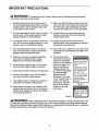
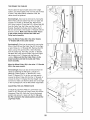
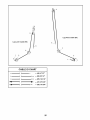
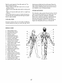
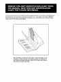
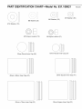
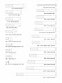
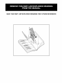
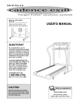
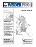
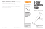
Model No. 831.159821
Serial No.
Write the serial number in the
USER'S MANUAL
space above for reference.
Serial Number Decal (under seat)
EXERCISE
EO
U
I
PM
ENT
HELPLINE!
!-800-736-6879
SEARS, ROEBUCK AND CO.
HOFFMAN ESTATES, IL 60179
CAUTION
Read all precautions and instructions in this manual before using
this equipment, Save this manual
for future reference,
. Visit our website at
www.weiderfitness.com
new products, prizes,
fitness tips, and much morel
TABLE OF CONTENTS
IMPORTANT PRECAUTIONS .............................................................
BEFORE YOU BEGIN ...................................................................
ASSEMBLY ...........................................................................
ADJUSTMENTS ......................................................................
WEIGHT RESISTANCE CHART ...........................................................
CABLE DIAGRAM .....................................................................
EXERCISE GUIDELINES ................................................................
ORDERING REPLACEMENT PARTS ................................................
FULL 90 DAY WARRANTY .......................................................
3
4
5
21
23
24
26
Back Cover
Back Cover
Note: A PART IDENTIFICATION CHART and a PART LIST/EXPLODED DRAWING are attached in the center of
this manual. Remove the PART IDENTIFICATION CHART and the PART LIST/EXPLODED DRAWING before
beginning assembly.
IMPORTANT PRECAUTIONS
WARNING:
To reduce the risk of serious injury, read the following
important precau-
tions before using the weight system,
Read all instructions in this manual and in
the accompanying literature before using the
weight system. Use the weight system only
as described in this manual,
11. Make sure that the cables remain on the pulleys at all times. If the cables bind while you
are exercising, stop immediately and make
sure that the cables are on all of the pulleys.
2.
It is the responsibility of the owner to ensure
that all users of the weight system are adequately informed of all precautions,
12. Always stand on the foot plate when performing an exercise that could cause the
weight system to tip.
3.
The weight system is intended for home use
only. Do not use the weight system in a commercial, rental, or institutional setting,
13. Always disconnect the lat bar from the
weight system when performing an exercise
that does not use the lat bar.
4.
Use the weight system only on a level surface. Cover the floor or carpet beneath the
weight system to protect the floor,
14. If you feel pain or dizziness at any time while
exercising, stop immediately and begin cooling down.
5.
Make sure all parts are properly tightened
each time the weight system is used.
Replace any worn parts immediately.
15. The warning decals
shown here have been
placed on the weight
system in the locations
shown on page 4. If a
decal is missing or
illegible, please call
our toll-free HELPLINE
at 1-800-736-6879,
Monday through
Saturday, 7 a.m. until
7 p.m. Central Time, to
order a free replacement decal. Place the
decal on the weight
system in the Iocation sh own.
6.
Keep children under the age of 12 and pets
away from the weight system at all times.
7.
Keep hands and feet away from moving parts.
8.
Always wear athletic shoes for foot protection when using the weight system.
9.
The weight system is designed to support a
maximum user weight of 300 pounds,
10. Never release the press arm, butterfly arms,
leg lever, leg press base, lat bar, ab strap, or
handle while weights are raised; the weights
will fall with great force.
• Misuseofthis product
mayresult_nserious
=n
jury.
• Readuser'smanual
and followall warnings
and operatinginstructions priorto use.
• Donot allowchildren
on or aroundmachine.
• Replacelabelif
damaged,illegible,or
removed.
Decal I
Decal 2
i WARNING:
Before beginning this or any exercise program, consult your physician. This
is especially important for persons over the age of 35 or persons with pre-existing health problems.
Read all instructions before using. SEARS assumes no responsibility for personal injury or property
damage sustained by or through the use of this product.
BEFORE YOU BEGIN
Thank you for selecting the versatile WELDER '_PRO
4100 weight system. The PRO 4100 weight system
offers a selection of weight stations designed to develop every major muscle group of the body. Whether
your goal is to tone your body, build dramatic muscle
size and strength, or improve your cardiovascular system, the weight system will help you to achieve the
results you want.
1-800-736-6879, Monday through Saturday, 7 a.m.
until 7 p.m. Central Time (excluding holidays). To help
us assist you, please note the product model number
and serial number before calling. The model number is
831.159821. The serial number can be found on a
decal attached to the weight system (see the front
cover of this manual).
Before reading further, please review the drawing
below and familiarize yourself with the parts that are
labeled.
For your benefit, read this manual carefully before
using the weight system. If you have additional
questions, please call our toll-free HELPLINE at
ASSEMBLED
DIMENSIONS:
Height:
Width:
Length:
Warning Decal 2
(One on each side
of the right upright.)
77 in.
81 in.
59 in.
Lat Bar
--
Butterfly Arm
/Press Arm
High Pulley Station
Left Side
Ab Pulley
Station
Warning
Decal 1
Backrest
Backrest
Right Side
Leg Press
Plate
Seat
Weight
Leg
__
Note: The terms "right side" and "left side" are determined relative to a person facing away from the weight system; they do
not correspond to right and left in the pictures in the manual.
4
SFoot
Low Pulley
Station
Plate
ASSEMBLY
• As you assemble the weight system, make sure
all parts are oriented as shown in the drawings.
Make Things Easier for Yourself
Everything in this manual is designed to ensure
that the weight system can be assembled successfully by anyone. However. it is important to
realize that the versatile weight system has
many paris and that the assembly process will
take time. Most people find that Dy setting aside
plenty of time. assembly will go smoothly.
• For help identifying small parts, use the PART
IDENTIFICATION CHART.
An Allen wrench
) and the following
tools (not included) are required for assembly:
• two adjustable wrenches
• one rubber mallet
Before beginning assembly, carefully read the
following information and instructions:
• one standard screwdriver
• Assembly requires two people.
• one Phillips screwdriver
• Place all parts in a cleared area and remove the
packing materials. Do not dispose of the packing
materials until assembly is completed.
• lubricant, such as grease or petroleum jelly,
and soapy water.
Assembly will be more convenient if you have a
socket set, a set of open-end or closed-end
wrenches, or a set of ratchet wrenches.
• Tighten all parts as you assemble them, unless
instructed to do otherwise.
FRAME ASSEMBLY
81
.
75
Before beginning assembly, be sure that you
have read and understand the information in
the box above.
Attach the Base Cap (28) to the Right Base (1)
with an M4 x 20mm Self-tapping Screw (77) and
an M5 Washer (50).
28
57
Attach the Center Base (67) to the Right Base (1)
with two M10 x 70mm Bolts (81), two M10
Washers (75), and two M10 Nylon Locknuts (70).
Do not tighten the Locknuts yet.
57
77
Insert four M10 x 65mm Carriage Bolts (57) up into
the Right Base (1).
.
33
Press two 50mm Square Inner Caps (33) into the
ends of the Left Base (2).
75_
81
Insert four M10 x 65mm Carriage Bolts (57) up into
the Left Base (2).
70
Attach the Left Base (2) to the Right Base (1) and
Center Base (67) with three M10 x 70mm Bolts
(81), three M10 Washers (75), and three M10
Nylon Locknuts (70).
67
33
57
57
Tighten the M10 Nylon Locknuts (70) used in
steps 1 and 2.
5
.
Attach the Base Plate (37) to the Left Base (2)
with an M10 x 135mm Bolt (58) and an M10
Nylon Locknut (70). Be sure that the texture
side is on top.
Attach the Left Upright (7) to the Left Base (2)
with the two indicated M10 x 65mm Carriage
Bolts (57) and two M10 Nylon Locknuts (70).
Attach the Left Leg (36) to the Left Base (2) with
the two indicated M10 x 65mm Carriage Bolts
(57) and two M10 Nylon Locknuts (70). Be sure
the large upper hole in the Left Leg is on the
side shown.
Do not tighten the M10 Nylon Locknuts (70)
yet.
36
e
Hole
ooo
_/7o
57
70
_/
.
Press a 50mm x 70mm Inner Cap (22) into the
top of the Right Leg (73).
Attach the Right Leg (73) to the Right Base (1)
with the two M10 x 65mm Carriage Bolts (57) and
two M10 Nylon Locknuts (70).
Attach the Right Upright (6) to the Right Base (1)
with the two indicated M10 x 65mm Carriage
Bolts (57) and two M10 Nylon Locknuts (70).
Do not tighten the M10 Nylon Locknuts (70)
yet.
22
7O
7O
oo?
57
1
57
6
37
5.
Attach the Right Seat Frame (5) to the Right Leg
(73) with two M10 x 85mm Bolts (60), two M10
Washers (75), and two M10 Nylon Locknuts (70).
5
6O
75
7O
Attach the Right Seat Frame (5) to the Right
Upright (6) with two M10 x 85mm Bolts (60), two
M10 Washers (75), and two M10 Nylon Locknuts
(70).
75
75
Do not tighten the M10 Nylon Locknuts (70)
yet.
75
.
Press a 50mm Square Inner Cap (33) into the
end of the Left Seat Frame (29).
75
60
57
Attach the Left Seat Frame (29) to the Left Leg
(36) with two M10 x 65mm Carriage Bolts (57)
and two M10 Nylon Locknuts (70).
29
Attach the Left Seat Frame (29) to the Left
Upright (7) with two M10 x 85mm Bolts (60), two
M10 Washers (75), and two M10 Nylon Locknuts
(70).
33
Do not tighten the M10 Nylon Locknuts (70)
yet.
.
Set two Weight Bumpers (83) over the indicated
holes in the Center Base (67). Insert the two
Weight Guides (20) into the holes. Attach the
Weight Guides to the Center Base with two M10 x
65mm Bolts (63), four M10 Washers (75), and
two M10 Nylon Locknuts (70).
83
83
r/ 70
70
63
.
Slide the eight Weights (72) onto the Weight
Guides (20) with the pin grooves on the side
shown.
Press the Weight Tube Bumper (32) into the bottom of the Weight Tube (82). Insert the Weight
Tube into the center hole in the stack of Weights
(72). Be sure the Weight Tube is oriented as
shown.
Lubricate the indicated holes in the Top Weight
(74). Slide the Top Weight onto the Weight
Guides (20), with the pin groove on the bottom.
.
Press two 50mm x 70mm Inner Caps (22) into
the ends of the Left Top Frame (3).
Attach the Left Top Frame (3) to the Left Upright
(7) with two M10 x 90mm Bolts (59), a Support
Plate (21), and two M10 Nylon Locknuts (70). Do
not tighten the Locknuts yet.
22
59
70
"7O
7
10. Press a 50mm x 70mm Inner Cap (22) into the
end of the Right Top Frame (8).
10
59
Attach the Right Top Frame (8) to the Right
Upright (6) with two M10 x 90mm Bolts (59), a
Support Plate (21), and two M10 Nylon Locknuts
(70).
22
Attach the Right Top Frame (8) to the Left Top
Frame (3) with two M10 x 70mm Bolts (81), two
M10 Washers (75), and two M10 Nylon Locknuts
(70).
Do not tighten the MIO Nylon Locknuts (70)
yet.
11.PressthetwoWeightGuideBushings(44)into
theCenterTopFrame(14).SlidetheCenterTop
FrameontotheWeightGuides(20).
11
AttachtheCenterTopFrame(14)tothe Right
TopFrame(8)withtwoM10x 70mmBolts(81),
twoM10Washers(75),andtwo M10Nylon
Locknuts(70).
7O
7O
81
81
AttachtheCenterTopFrame(14)tothe LeftTop
Frame(3)withtwoM10x 70mmBolts(81),two
M10Washers(75),andtwoM10NylonLocknuts
(7O).
75
Tighten all of the M10 Nylon Locknuts (70)
used in steps 3-11.
12
12. Press a 38mm Square Inner Cap (41) into the
Right Upright (6). Press a 50mm x 70mm Inner
Cap (22) into the Butterfly Frame (9).
22
Lubricate an M10 x 80mm Bolt (61) with grease.
Attach the Butterfly Frame (9) to the Right Top
Frame (8) with the Bolt and an M10 Nylon Locknut
(70). Do not overtighten the Locknut; the
Butterfly Frame must be able to pivot easily.
-'"
Lubricate
1
13. Lubricate an M10 x 50mm Bolt (62) with grease.
Attach the Pivot Bracket (48) to the Right Butterfly
Arm (11)with the Bolt and an M10 Nylon Locknut
(70). Do not overtighten the Locknut; the Pivot
Bracket must be able to pivot easily.
13
Lub rica te....__Tf
Press a 40mm x 50mm Inner Cap (23) into the
indicated end of the Right Butterfly Arm (11). Wet
the bottom end of the Arm with soapy water. Slide
a Large Foam Pad (19) onto the Arm.
26/'
/'//"
,"'/",/' 64
Slide a Foam Grip (76) onto a Press Handle (12).
Press a 25mm Round Inner Cap (24) into the end
of the Handle. Attach the Handle to the Right
Butterfly Arm (11) with two M8 x 16mm Bolts (64)
and two M8 Washers (26).
62
23
11
70
10
/' /
Slide the Large Foam Pad (19) down so that the
bottom of the Foam Pad is even with the bottom
of the Right Butterfly Arm (11).
Repeat this step with the Left Butterfly Arm
(10).
Q
ii
12
14. Lubricate an M10 x 80mm Button Head Bolt (97)
and both sides of two Plastic Washers (55) with
grease. Attach the Right Butterfly Arm (11) to the
Butterfly Frame (9) with the Bolt, the two Plastic
Washers, two Butterfly Caps (54), and an M10
Nylon Locknut (70). Do not overtighten the
Locknut; the Butterfly Arm must be able to
pivot easily. Be sure the indented sides of the
Plastic Washers fit over the welded bushing in
the Butterfly Arm.
14
Lubricate
97
Welded
Bushing
11
\
/ Lubricate
/
10
7O
Repeat this step with the Left Butterfly Arm
(10).
15. Attach the Bumper (25) to the Right Leg (73) with
an M4 x 20mm Self-tapping Screw (77) and an
M5 Washer (50).
15
73
23
Press two 40mm x 50mm Inner Caps (23) into
the ends of the Leg Lever (4).
Lubricate
7O
Lubricate an M10 x 60mm Bolt (63) with grease.
Attach the Leg Lever (4) to the Right Leg (73)
with the Bolt and an M10 Nylon Locknut (70). Do
not overtighten the Locknut; the Leg Lever
must be able to pivot easily.
16. Press a 50mm x 70mm Inner Cap (22) into the
top of the Leg Press Frame (30).
16
Lubricate an M10 x 80mm Bolt (61) with grease.
Attach the Leg Press Frame (30) to the Left Base
(2) with the Bolt and an M10 Nylon Locknut (70).
Do not overtighten the Locknut; the Leg Press
Frame must be able to pivot easily.
30
7O
61
;
10
Lubricate
CABLE
17
ASSEMBLY
38
17. IMPORTANT: While assembling the cables, do
not over tighten the Iocknuts attaching the pul,
leys; the pulleys must be able to turn freely.
Refer to the CABLE DIAGRAMS and CABLE ID
CHART on pages 24 and 25 for proper cable
routing and help identifying the cables.
75
Locate the High Cable (45). Route the Cable up
through the Left Top Frame (3) and around a
90mm Pulley (38). Attach the Pulley inside the
Top Frame with an M10 x 70mm Bolt (81), two
M10 Washers (75), two 13mm Spacers (34), and
an M10 Nylon Locknut (70).
45
7O
18
91
18. Route the High Cable (45) around a 90mm Pulley
(38) and down through the Left Top Frame (3).
Attach the Pulley and a Cable Trap (91) inside
the Top Frame with an M10 x 70mm Bolt (81),
two M10 Washers (75), two 13mm Spacers (34),
and an M10 Nylon Locknut (70). Be sure the
Cable Trap is turned to hold the Cable in the
groove of the Pulley.
75
34
\
38
7O
81
.45
3
Note: To complete this step, it may be necessary to loosen the indicated M10 Nylon
Locknuts (70). Retighten the Locknuts when
this step is completed.
19
19. Wrap the High Cable (45) around a 90mm Pulley
(38). Attach the Pulley to the single hole side of a
Double "U"-Bracket (56) with an M10 x 45mm
Bolt (66) and an M10 Nylon Locknut (70).
20. Note: The following drawings are shown from
the left side of the weight system, with the
Left Top Frame (3) removed for clarity.
2O
Wrap the High Cable (45) around a 90mm Pulley
(38). Attach the Pulley at the rear hole, inside of
the bracket on the Center Top Frame (14) with an
M10 x 45mm Bolt (66) and an M10 Nylon Locknut
(70).
38
66
__45
11
21. Wrap the High Cable (45) around a 90mm Pulley
(38). Attach the Pulley at the forward hole, inside
of the bracket on the Center Top Frame (14) with
an M10 x45mm Bolt (66) and an M10 Nylon
Locknut (70).
21
7O
_14
--45
38
J
22. Attach the end of the High Cable (45) to the
Small "U"-Bracket (79) with an M8 Washer (26)
and an M8 Nylon Locknut (71). Note: Do not
completely tighten the Nylon Locknut; it
should be threaded only two turns onto the
end of the Cable, as shown in the inset drawing.
22
Attach the Small "U"-Bracket (79) to the Weight
Tube (82) with an M8 x 45mm Bolt (69) and an
M8 Nylon Locknut (71). Do not overtighten the
Locknut; the Weight Tube should be able to
pivot in the "U"-Bracket.
23. Locate the Leg Press Cable (95). Attach the
Cable inside the Left Leg (36) with aM10 x 70mm
Bolt (81), two M10 Washers (75), two Long
Spacers (80), and an M10 Nylon Locknut (70).
75
8O
75
36
24. Wrap the Leg Press Cable (95) around a 90mm
Pulley (38). Attach the Pulley inside the Leg
Press Frame (30) with an M10 x 70mm Bolt (81),
two M10 Washers (75), two 13mm Spacers (34),
and an M10 Nylon Locknut (70).
24
34
95
81
12
7O
25. Route the Leg Press Cable (95) through the Left
Leg (36) and the Left Upright (7) as shown. Wrap
the Cable around a 90mm Pulley (38). Attach the
Pulley inside the Upright with an M10 x 70mm
Bolt (81), two MIO Washers (75), two 13mm
Spacers (34), and an MIO Nylon Locknut (70).
26. Wrap the Leg Press Cable (95) around a 90mm
Pulley (38). Attach the Pulley inside the bracket
on the Left Top Frame (3) with an M10 x 45mm
Bolt (66) and an M10 Nylon Locknut (70).
27. Attach the end of the Leg Press Cable (95) to the
"U"-Bracket (85) with an M8 Washer (26) and an
M8 Nylon Locknut (71). Note: Do not completely tighten the Locknut; it should be threaded
only two turns onto the end of the Cable, as
shown in the inset drawing.
27
/95
26
71
_-//-//-//-/
28. Locate the Butterfly Cable (46). Attach the
Cable to the Pivot Bracket (48) on the Left
Butterfly Arm (10) with an M8 x 16mm Shoulder
Bolt (78) and an M8 Nylon Locknut (71).
28
10
13
/
29. Wrap the Butterfly Cable (46) around a "V"-Pulley
(39). Attach the Pulley and a Long Cable Trap
(40) to the bracket on the Right Upright (6) with
an M10 x 60mm Bolt (65) and an M10 Nylon
Locknut (70). Be sure the Cable Trap is turned
to hold the Cable in the groove of the Pulley.
29
65
30. Wrap the Butterfly Cable (46) around a 90mm
Pulley (38). Attach the Pulley to the single hole
side of the other Double "U"-Bracket (56) with an
M10 x 45mm Bolt (66) and an M10 Nylon Locknut
(7O).
3O
56
31. Wrap the Butterfly Cable (46) around a "V"-Pulley
(39). Attach the Pulley and a Long Cable Trap
(40) to the bracket on the Right Upright (6) with
an M10 x 60mm Bolt (65) and an M10 Nylon
Locknut (70). Be sure the Cable Trap is turned
to hold the Cable in the groove of the Pulley.
31
65
46
\
39
32. Attach the Butterfly Cable (46) to the Pivot
Bracket (48) on the Right Butterfly Arm (11) with
an M8 x 16mm Shoulder Bolt (78) and an M8
Nylon Locknut (71).
32
78
46
11
48
71
14
33. Locate the Leg Lever Cable (96). Route the
eyelet end of the Cable through the Right Leg
(73) and attach it to the Leg Lever (4) with an
M10 x 25mm Shoulder Bolt (99) and an M10
Nylon Locknut (70).
33
96
34. Attach a 90mm Pulley (38) inside the Right Leg
(73) with an M10 x 70mm Bolt (81), two M10
Washers (75), two 13mm Spacers (34), and an
M10 Nylon Locknut (70).
99
34
34
,75
81
35. Route the Leg Lever Cable (96) through the Right
Upright (6) and around a 90mm Pulley (38).
Attach the Pulley inside the Upright with an M10 x
70mm Bolt (81), two M10 Washers (75), two
13mm Spacers (34), and an M10 Nylon Locknut
(70).
35
36. Wrap the Leg Lever Cable (96) around a 90mm
Pulley (38). Attach the Pulley and a Cable Trap
(91) to the second set of holes from the bottom of
the indicated Double "U"-Bracket (56) with an
M10 x 50mm Bolt (62) and an M10 Nylon Locknut
(70). Be sure the Cable Trap is turned to hold
the Cable in the groove of the Pulley.
36
15
37. Attach the end of the Leg Lever Cable (96) to the
other "U'-Bracket (85) with an M8 Washer (26)
and an M8 Nylon Locknut (71). Note: Do not
completely tighten the Nylon Locknut; it
should be threaded only two turns onto the
end of the Cable, as shown in the inset drawing.
37
t
38. Locate the Low Cable (47). Route the small ball
on the Cable through the cage on the Leg Press
Frame (30).
38
' "_-_\
38
Attach a 90mm Pulley (38) inside the Leg Press
Frame (30) with an M10 x 70mm Bolt (81), two
M10 Washers (75), two 13mm Spacers (34), and
an M10 Nylon Locknut (70).
34
81/J 75
39. Route the Low Cable (47) through the Left Leg
(36) and the Left Upright (7). Attach a 90mm
Pulley (38)inside the Upright with an M10 x
70mm Bolt (81), two M10 Washers (75), two
13mm Spacers (34), and an M10 Nylon Locknut
(70).
C
81
40. Wrap the Low Cable (47) around a 90mm Pulley
(38). Attach the Pulley and a Cable Trap (91) to
the lower set of holes in the indicated "U"-Bracket
(85) with an M10 x 50mm Bolt (62) and an M10
Nylon Locknut (70). Be sure the Cable Trap is
turned to hold the Cable in the groove of the
Pulley.
75
_70
_
16
91
70
41. Wrap the Low Cable (47) around a 90mm Pulley
(38). Attach the Pulley to the indicated bracket on
the Left Base (2) with an M10 x 45mm Bolt (66)
and an M10 Nylon Locknut (70).
66
2
42. Wrap the Low Cable (47) around a 90mm Pulley
(38). Attach the Pulley to the indicated bracket on
the Left Base (2) with an M10 x 45mm Bolt (66)
and an M10 Nylon Locknut (70).
38
43. Wrap the Low Cable (47) around a 90mm Pulley
(38). Attach the Pulley and a Cable Trap (91) to
the second set of holes from the bottom of the
43
indicated Double "U"-Bracket (56) with an M10 x
50mm Bolt (62) and an M10 Nylon Locknut (70).
Be sure the Cable Trap is turned to hold the
Cable in the groove of the Pulley.
38
44. Wrap the Low Cable (47) around a 90mm Pulley
(38). Attach the Pulley to the indicated bracket on
the Right Base (1) with an M10 x 45mm Bolt (66)
and an M10 Nylon Locknut (70).
_8
/
7O
17
45. Wrap the Low Cable (47) around a 90mm Pulley
(38). Attach the Pulley to the indicated bracket on
the Right Base (1) with an M10 x 45mm Bolt (66)
and an M10 Nylon Locknut (70).
I
45
66
46. Wrap the Low Cable (47) around a 90mm Pulley
(38). Attach the Pulley and a Cable Trap (91) to
the lower set of holes in the indicated "U"-Bracket
46
(85) with an M10 x 50mm Bolt (62) and an M10
Nylon Locknut (70). Be sure the Cable Trap is
turned to hold the Cable in the groove of the
Pulley.
47. Wrap the Low Cable (47) around a 90mm Pulley
(38). Attach the Pulley and a Cable Trap (91) to
the side of the Right Upright (6) with an M10 x
95mm Bolt (98), an M10 Washer (75), and an
M10 Nylon Locknut (70). Be sure the Cable Trap
is turned to hold the Cable in the groove of
the Pulley.
47
47
98
75
48. Wrap the Low Cable (47) around a 90mm Pulley
(38). Attach the Pulley and a pair of Pulley
Covers (92) to the Right Upright (6) with an M10
x 100mm Bolt (84), two M10 Washers (75), and
an M10 Nylon Locknut (70). Be sure the small
tabs on the Pulley Covers are on the side
shown, and the Cable is between the Pulley
and the rod on the Upright.
48
Small
Tabs
75
84
38
47
18
7O
SEAT
49
ASSEMBLY
49. Attach a Seat (16) to the Right Seat Frame (5)
with an M6 x 63mm Bolt (90), an M6 Washer
(35), and two M6 x 16mm Bolts (13).
Repeat this step with the other Seat (16) and
the Left Seat Frame (not shown).
50. Attach a Backrest (15) to the Right Upright (6)
with four M6 x 16mm Bolts (13).
50
Repeat this step with the other Backrest (15)
and the Left Upright (not shown).
13
13
51. Slide the Long Pad Tube (17) through the hole in
the Right Leg (73). Slide two Foam Pads (18)
onto the ends of the Pad Tube. Press two 19mm
51
Round Inner Caps (27) into the ends of the Pad
Tube.
18
27
Repeat this step with the Short Pad Tube (94)
and the Leg Lever (4).
73
52. Press a 50mm x 70mm Inner Cap (22) into the
indicated end of the Adjustment Tube (88).
52
87
Attach the Leg Press Plate (31) to the Adjustment
Tube (88) with an M8 x 65mm Bolt (89), two M8
Washers (26), and an M8 Nylon Locknut (71).
22
88
Attach the Adjustment Tube (88) to the Leg Press
Frame (30) with the Leg Press Pin (87). Be sure
the Pin is in the locked position around the
Leg Press Frame.
26
71
26
31
19
53. Insert the two Locking Pins (53) into the Butterfly
Frame (9). Attach the tether on the Pins to the
Butterfly Frame with an M4 x 9.5mm Self-tapping
Screw (68). Do not fully tighten the Screw.
53
53
54. Make sure that all parts have been properly tightened. The use of all remaining parts will be explained in
ADJUSTMENTS, starting on the following page.
Before using the weight system, pull each cable a few times to make sure that the cables move smoothly
over the pulleys. If one of the cables does not move smoothly, find and correct the problem. IMPORTANT" If
the cables are not properly routed, they may be damaged when heavy weight is used. See the CABLE
DIAGRAM on pages 24 and 25 of this manual for proper cable routing. If there is any slack in the
cables, you will need to remove it by tightening the cables; see TIGHTENING THE CABLES on page
22.
20
ADJUSTMENTS
This section explains how to adjust the weight system. See the EXERCISE GUIDELINES on page 26 for important information about how to get the most benefit from your exercise program. Also, refer to the accompanying
exercise guide to see the correct form for each exercise.
Make sure all parts are properly tightened each time the weight system is used. Replace any worn parts immediately. The weight system can be cleaned with a damp cloth and a mild, non-abrasive detergent. Do not use solvents.
ATTACHING THE ACCESSORIES
STATION
TO A PULLEY
Attach the Lat Bar (42) to the High Cable (45) with a
Cable Clip (52). For some exercises, the Chain (not
shown) should be attached between the Lat Bar and
the High Cable with two Cable Clips. Adjust the
length of the Chain between the Lat Bar and the
High Cable so the Lat Bar is in the correct starting position for the exercise to be performed.
42
The Handle (not shown) and Ab Strap (not shown)
can be attached in the same manner. The accessories can be attached to the Low Cable (not shown)
in the same manner.
CHANGING THE WEIGHT SETTING
To change the weight setting of the weight stack,
insert the Weight Pin (86) under the desired Weight
(72). Be sure to insert the Weight Pin until the bent
end of the Weight Pin is touching the Weights, and
turn the bent end downward. The weight setting of the
weight stack can be changed from 6 pounds to 106
pounds, in increments of 12.5 pounds. Note: Due to
the cables and pulleys, the actual amount of
resistance at each exercise station may vary from
the weight setting. Use the WEIGHT RESISTANCE
CHART on page 23 to find the actual amount of
resistance at each weight station.
J
CONVERTING THE BUTTERFLY ARMS
To use the Butterfly Arms (10, 11) as butterfly arms,
insert the Locking Pins (53) into the butterfly holes in
the Right Upright (6).
Butterfly
Holes
To use the Butterfly Arms (10, 11) as press arms,
insert the Locking Pins (53) into the press holes in the
Butterfly Frame (9).
9
11
X
Make sure that the Locking Pins (53) are fully
inserted into the same set of holes before performing any exercises.
Press
Holes
21
TIGHTENING THE CABLES
Woven cable, the type of cable used on the weight
system, can stretch slightly when it is first used. If there
is slack in the cables before resistance is felt, the
cables should be tightened.
See drawing A. Slack can be removed by moving the
90mm Pulley (38) and Cable Trap (91) to a higher set
of holes in a Double "U"-Bracket (56). Remove the
M10 Nylon Locknut (70) and the M10 x 50mm Bolt (62)
from the Cable Trap, the Pulley, and the Double "U"Bracket. Re-attach the Pulley and the Cable Trap to
the new set of holes in the Double "U"-Bracket with the
Bolt and Locknut. Make sure that the Cable Trap is
in the proper position and that the Cable and
Pulley move smoothly.
38
Move the 90mm Pulley (38) in the other Double
"U"-Bracket (56) in the same manner.
See drawing B. Slack can be removed by moving the
90mm Pulley (38) and the Cable Trap (91) to the higher set of holes in a "U"-Bracket (85). Remove the M10
Nylon Locknut (70) and the M10 x 50mm Bolt (62)
from the Cable Trap, the Pulley, and the "U"-Bracket.
Re-attach the Pulley and the Cable Trap to the higher
set of holes in the "U"-Bracket with the Bolt and
Locknut. Make sure that the Cable Trap is in the
proper position and that the Cable and Pulley
move smoothly.
79
Move the 90mm Pulley (38) in the other "U"-Bracket
(85) in the same manner.
See drawing B. Slack can also be removed from the
cables by tightening the M8 Nylon Locknuts (71)
attaching a cable to either "U"-Bracket (85), or the
Small "U"-Bracket (79). To do this, you may need to
remove the 90mm Pulley (38) from the "U"-Bracket, or
remove the Small "U"-Bracket from the Weight Tube
(not shown). Make sure that the cables are not too tight
or the Top Weight (74) will be lifted off the weight stack.
79
ADJUSTING THE LEG PRESS PLATE
To adjust the Leg Press Plate (31), remove the Leg
Press Pin (87) from the Leg Press Frame (30) and the
Adjustment Tube (88). Move the Tube to the desired
position and secure it in place with the Pin. Be sure
the Pin is turned to the locked position around the
Leg Press Frame.
31
22
WEIGHT RESISTANCE
CHART
The chart below shows the approximate weight resistance at each exercise station. "Top" refers to the 6 lb. top
weight. The other numbers refer to the 12.5 lb. weight plates. Weight resistance shown for the butterfly arm station is for each butterfly arm. Note: The actual resistance at each station may vary due to differences in
individual weight plates as well as friction between the cables, pulleys, and weight guides.
WEIGHT
HIGH
PULLEY
(Ibs.)
PRESS
ARM
(Ibs.)
LEG
PRESS
(Ibs.)
BUTTERFLY ARM
(Ibs.)
AB
PULLEY
(Ibs.)
LEG
LEVER
(Ibs.)
LOW
PULLEY
(Ibs.)
LeffTop
13
20
27
16
27
22
16
1
27
40
68
28
42
48
32
2
46
59
98
41
56
74
49
3
59
79
128
53
70
94
64
4
74
103
156
68
82
121
79
5
87
117
176
77
95
134
93
6
102
136
202
87
110
155
108
7
115
161
237
97
125
173
122
8
129
180
265
108
139
193
137
23
CABLE DIAGRAMS
The cable diagrams below show the proper routing of the High Cable (45), the Butterfly Cable (46), the Low
Cable (47), the Leg Press Cable (95), and the Leg Lever Cable (96). Use the diagrams to make sure that the
cables and the cable traps have been assembled correctly, tf the cables have not been correctly routed, the
weight system will not function properly and damage may occur. The numbers show the correct route for each
cable. Make sure that the cable traps do not touch or bind the cables.
2
3
Butterfly Cable (46)
\
High Cable (45)
6
11
Low Cable (47)
10
24
1
Leg Press Cable (95)
Leg Lever Cable (96)
1
2
CABLE ID CHART
-- (46) 47 3/7"
-- (96) 95 1/2"
7
7
c--=
ly
÷ ,,
_
-- (95) 148 1/4"
r_?.}
-- (47) 276 3/4"
¢_
-- (45) 116 3/4"
25
EXERCISE GUIDELINES
THE FOUR BASIC TYPES OF WORKOUTS
PERSONALIZING
Muscle Building
To increase the size and strength of your muscles,
push them close to their maximum capacity. Your muscles will continually adapt and grow as you progressively increase the intensity of your exercise. You can
adjust the intensity level of an individual exercise in
two ways:
• by changing the amount of weight used
• by changing the number of repetitions or sets performed. (A "repetition" is one complete cycle of an
exercise, such as one sit-up. A "set" is a series of
repetitions.)
Determining the exact length of time for each workout,
as well as the number of repetitions or sets completed,
is an individual matter, tt is important to avoid overdoing it during the first few months of your exercise program. You should progress at your own pace and be
sensitive to your body's signals, tf you experience pain
or dizziness at any time while exercising, stop immediately and begin cooling down. Find out what is wrong
before continuing. Remember that adequate rest and a
proper diet are important factors in any exercise program.
WARMING
The proper amount of weight for each exercise
depends upon the individual user. You must gauge
your limits and select the amount of weight that is right
for you. Begin with 3 sets of 8 repetitions for each
exercise you perform. Rest for 3 minutes after each
set. When you can complete 3 sets of 12 repetitions
without difficulty, increase the amount of weight.
YOUR EXERCISE PROGRAM
UP
Begin each workout with 5 to 10 minutes of stretching
and light exercise to warm up. Warming up prepares
your body for more strenuous exercise by increasing
circulation, raising your body temperature and delivering more oxygen to your muscles.
WORKING OUT
Toning
You can tone your muscles by pushing them to a moderate percentage of their capacity. Select a moderate
amount of weight and increase the number of repetitions in each set. Complete as many sets of 15 to 20
repetitions as possible without discomfort. Rest for 1
minute after each set. Work your muscles by completing more sets rather than by using high amounts of
weight.
Each workout should include 6 to 10 different exercises. Select exercises for every major muscle group,
emphasizing areas that you want to develop most. To
give balance and variety to your workouts, vary the
exercises from session to session.
Schedule your workouts for the time of day when your
energy level is the highest. Each workout should be
followed by at least one day of rest. Once you find the
schedule that is right for you, stick with it.
Weight Loss
To lose weight, use a low amount of weight and
increase the number of repetitions in each set.
Exercise for 20 to 30 minutes, resting for a maximum
of 30 seconds between sets.
EXERCISE FORM
Maintaining proper form is an essential part of an
effective exercise program. This requires moving
through the full range of motion for each exercise, and
moving only the appropriate parts of the body.
Exercising in an uncontrolled manner will leave you
feeling exhausted. On the exercise guide accompanying this manual you will find photographs showing the
correct form for several exercises, and a list of the
muscles affected. Refer to the muscle chart on page
27 to find the names of the muscles.
Cross Training
Cross training is an efficient way to get a complete and
well-balanced fitness program. An example of a balanced program is:
• Plan weight training workouts on Monday,
Wednesday, and Friday.
• Plan 20 to 30 minutes of aerobic exercise, such as
cycling or swimming, on Tuesday and Thursday.
• Rest from both weight training and aerobic exercise
for at least one full day each week to give your body
time to regenerate.
The repetitions in each set should be performed
smoothly and without pausing. The exertion stage of
each repetition should last about half as long as the
return stage. Proper breathing is important. Exhale
during the exertion stage of each repetition and inhale
during the return stroke. Never hold your breath.
The combination of weight training and aerobic exercise will reshape and strengthen your body, plus develop your heart and lungs.
26
Rest for a short period of time after each set. The
ideal resting periods are:
• Rest for three minutes after each set for a muscle
slowly as you stretch and do not bounce. Ease into
each stretch gradually and go only as far as you can
without strain. Stretching at the end of each workout
is an effective way to increase flexibility.
building workout.
• Rest for one minute after each set for a toning workout.
STAYING MOTIVATED
• Rest for 30 seconds after each set for a weight loss
workout.
Plan to spend the first couple of weeks familiarizing
yourself with the equipment and learning the proper
form for each exercise.
For motivation, keep a record of each workout, list the
date, the exercises performed, the weight used, and
the numbers of sets and repetitions completed.
Record your weight and key body measurements at
the end of every month. Remember, the key to
achieving the greatest results is to make exercise a
regular and enjoyable part of your everyday life.
COOLING DOWN
End each workout with 5 to 10 minutes of stretching.
Include stretches for both your arms and legs. Move
MUSCLE CHART
A.
B.
C.
D.
E.
F.
G.
H.
I.
J.
K.
L.
M.
N.
O.
R
Q.
R.
S.
T.
U.
V.
W.
Sternomastoid (neck)
Pectoralis Major (chest)
Biceps (front of arm)
Obliques (waist)
Brachioradials (forearm)
Hip Flexors (upper thigh)
Abductor (outer thigh)
Quadriceps (front of thigh)
Sartorius (front of thigh)
Tibialis Anterior (front of calf)
Soleus (front of calf)
RectusAbdominus (stomach)
Adductor (inner thigh)
Trapezius (upper back)
Rhomboideus (upper back)
Deltoid (shoulder)
Triceps (back of arm)
Latissimus Dorsi (mid back)
Spinae Erectors (lower back)
Gluteus Medius (hip)
Gluteus Maximus (buttocks)
Hamstring (back of leg)
Gastrocnemius (back of calf)
C
\
R
D_
S
J
"V
W
27
This chart is provided to help you identify the small parts used in assembly. The number in parenthesis below
each part refers to the key number of the part from the PART LIST in the center of this manual. Important:
Some parts may have been pre-assembled
for shipping. If you cannot find a part in the parts bags,
check to see if it has been pre-assembled.
Note: Assembly is divided into four stages: 1) frame assembly, 2) arm
assembly, 3) cable assembly, and 4) seat assembly. The hardware for
each stage is packaged separately. Wait until you begin each stage to
open the parts bag for that stage.
PART IDENTIFICATION
CHART--Model
No. 831.159821
M5 Washer
M6 Washer
M8 Washer
M10 Washer
R0403A
(50)
(35)
(26)
(75)
M10 Nylon Locknut
25mm Round Inner Cap (24)
40ram x 50mm Inner Cap (23)
50mm x 70mm Inner Cap (22)
(70)
M8 Nylon Locknut
19mm Round
(71)
Inner Cap (27)
38mm Square
50mm Square
Inner Cap (41)
Inner Cap (33)
M6 x 63mm Screw (90)
MIO x 60mm Bolt (65)
M8 x 65mm Bolt (89)
MIO x 50mm Bolt (62)
MIO x 65mm Bolt (63)
MIO x 45mm Bolt (66)
M10 x 70ram
M8 x 45ram
Bolt (69)
M10 x 65ram
MIO x 25mm Shoulder
M8 x 16mm Shoulder
Carriage
Bolt (57)
Bolt (99)
M10 x 80ram
Bolt (61)
Button
Bolt (97)
Bolt (78)
M10 x 80ram
M4 x 20ram
Bolt (81)
Self-tapping
Screw
Head
(77)
MIO x 85mm Bolt (60)
M8 x 16ram
Bolt (64)
M6 x 16ram
Bolt (13)
M4 x 9.5ram
Self-tapping
Screw
(68)
M10 x 90ram
Bolt (59)
M10 x 95ram
Bolt (98)
M10 x 100ram
Bolt (84)
M10 x 135mm
Bolt (58)
SAVE THIS PART LIST/EXPLODED
DRAWING
FOR FUTURE REFERENCE
PART LIST--Model
No. 831.159821
R0403A
Key No.
Qty.
Description
Key No.
Qty.
1
2
1
1
Right Base
Left Base
53
54
2
4
3
4
5
6
7
8
9
10
11
12
13
14
15
16
17
18
19
20
21
22
23
24
25
26
1
1
1
1
1
1
1
1
1
2
12
1
2
2
1
4
2
2
2
7
4
2
1
9
Left Top Frame
Leg Lever
Right Seat Frame
Right Upright
Left Upright
Right Top Frame
Butterfly Frame
Left Butterfly Arm
Right Butterfly Arm
Press Handle
M6 x 16mm Bolt
Center Top Frame
Backrest
Seat
Long Pad Tube
Foam Pad
Large Foam Pad
Weight Guide
Support Plate
50mm x 70mm Inner Cap
40mm x 50mm Inner Cap
25mm Round Inner Cap
Bumper
M8 Washer
55
56
57
58
59
60
61
62
63
64
65
66
67
68
69
70
71
72
73
74
75
76
77
78
4
2
10
1
4
6
2
6
3
4
2
9
1
1
1
68
7
8
1
1
42
2
2
2
27
28
29
4
1
1
19mm Round Inner Cap
Base Cap
Left Seat Frame
79
80
81
1
2
20
30
31
32
33
34
35
1
1
1
3
16
2
Leg Press Frame
Leg Press Plate
Weight Tube Bumper
50mm Square Inner Cap
13mm Spacer
M6 Washer
82
83
84
85
86
87
1
2
1
2
1
1
36
37
38
39
40
41
42
43
44
45
46
47
48
49
50
51
52
1
1
23
2
2
1
1
2
2
1
1
1
2
1
2
1
3
Left Leg
Left Base Plate
90mm Pulley
"V"-Pulley
Long Cable Trap
38mm Square Inner Cap
Lat Bar
Handgrip
Weight Guide Bushing
High Cable
Butterfly Cable
Low Cable
Pivot Bracket
Chain
M5 Washer
Handle
Cable Clip
88
89
90
91
92
93
94
95
96
97
98
99
#
#
#
#
1
1
2
6
2
1
1
1
1
2
1
1
1
1
1
1
Note: "#" indicates a non-illustrated
part. Specifications
Description
Locking Pin
Butterfly Cap
Plastic Washer
Double "U"-Bracket
M10 x 65mm Carriage Bolt
M10 x 135mm Bolt
M10 x 90mm Bolt
M10 x 85mm Bolt
M10 x 80mm Bolt
M10 x 50mm Bolt
M10 x 65mm Bolt
M8 x 16mm Bolt
M10 x 60mm Bolt
M10 x 45mm Bolt
Center Base
M4 x 9.5mm Self-tapping Screw
M8 x 45mm Bolt
M10 Nylon Locknut
M8 Nylon Locknut
Weight
Right Leg
Top Weight
M10 Washer
Foam Grip
M4 x 20mm Self-tapping Screw
M8 x 16mm Shoulder Bolt
Small "U"-Bracket
Long Spacer
M10 x 70mm Bolt
Weight Tube
Weight Bumper
M10 x 100mm Bolt
"U"-Bracket
Weight Pin
Leg Press Pin
Adjustment Tube
M8 x 65mm Bolt
M6 x 63mm Screw
Cable Trap
Pulley Cover
Ab Strap
Short Pad Tube
Leg Press Cable
Leg Lever Cable
M10 x 80mm Button Head Bolt
M10 x 95mm Bolt
M10 x 25mm Shoulder Bolt
User's Manual
Exercise Guide
Allen Wrench
Grease Packet
are subject to change without notice.
.<
¢0
0
0
rY
L9
L9
OL
/OL
9£
99
'E.
gL
Lg
ol
OZ
9£
OL
8
'
99
££
69
O: 9£'_0L/_;
SEARS
The model number and serial number of your WELDER _ PRO
4100 weight system are listed on a decal attached to the frame.
See the front cover of this manual to find the location of the
decal.
Model No. 831.159821
QUESTIONS?
If you find that:
• you need help assembling or
operating the WELDER _ PRO
4100 weight system
• a part is missing
• or you need to schedule repair
service
All replacement parts are available for immediate purchase or
special order when you visit your nearest SEARS Service
Center. To request service or to order parts by telephone, call the
toll-free numbers listed at the left.
When requesting help or service, or ordering parts, please be
prepared to provide the following information:
• The MODEL NUMBER of the product (831.159821)
• The NAME of the product (WELDER _*PRO 4100 weight system)
call our toll-free HELPLINE
1-800-736-6879
Monday-Saturday, 7 am-7 pm
Central Time (excluding holidays)
• The KEY NUMBER and DESCRIPTION of the PART (see the
PART LIST and EXPLODED DRAWING in the center of this
manual)
SEARS, ROEBUCK AND CO., HOFFMAN ESTATES, IL 60179
REPLACEMENT
PARTS
If parts become worn and need to
be replaced, call the following tollfree number
1-800-FON-PART
(1-800-366-7278)
FULL 90 DAY WARRANTY
For 90 days from the date of purchase, if failure occurs due to defect in material or workmanship in this
SEARS WEIGHT SYSTEM EXERCISER, contact the nearest SEARS Service Center throughout the
United States and SEARS will repair or replace the WEIGHT SYSTEM EXERCISER, free of charge.
This warranty does not apply when the WEIGHT SYSTEM EXERCISER is used commercially or for
rental purposes.
This warranty gives you specific legal rights, and you may also have other rights which vary from state
to state.
SEARS, ROEBUCK AND CO., DEPT. 817WA, HOFFMAN ESTATES, IL 60179
Part No. 189967 R0403A
Printed in China © 2002 Sears, Roebuck and Co.