1
Manual
Disclaimer
The information in this document is subject to change without notice and does not represent a
commitment on the part of Native Instruments GmbH. The software described by this document is subject to a License Agreement and may not be copied to other media. No part of this
publication may be copied, reproduced or otherwise transmitted or recorded, for any purpose,
without prior written permission by Native Instruments GmbH, hereinafter referred to as Native
Instruments.
“Native Instruments”, “NI” and associated logos are (registered) trademarks of Native Instruments GmbH.
Mac, Mac OS, GarageBand, Logic, iTunes and iPod are registered trademarks of Apple Inc.,
registered in the U.S. and other countries.
Windows, Windows Vista and DirectSound are registered trademarks of Microsoft Corporation
in the United States and/or other countries.
All other trade marks are the property of their respective owners and use of them does not imply any affiliation with or endorsement by them.
Document authored by: Native Instruments GmbH
Contact
NATIVE INSTRUMENTS GmbH
Schlesische Str. 29-30
D-10997 Berlin
Germany
www.native-instruments.de
NATIVE INSTRUMENTS North America, Inc.
6725 Sunset Boulevard
5th Floor
Los Angeles, CA 90028
USA
www.native-instruments.com
NATIVE INSTRUMENTS K.K.
YO Building 3F
Jingumae 6-7-15, Shibuya-ku,
Tokyo 150-0001
Japan
www.native-instruments.co.jp
NATIVE INSTRUMENTS UK Limited
18 Phipp Street
London EC2A 4NU
UK
www.native-instruments.com
© NATIVE INSTRUMENTS GmbH, 2015. All rights reserved.
Table of Contents
Table of Contents
1
Welcome to the REAKTOR Factory Library ................................................................... 17
2
Effects ...................................................................................................................... 18
2.1
Analogic Filter Box ...................................................................................................................... 18
2.1.1
Introduction ............................................................................................................... 18
2.1.2
Structure and Signal Flow ......................................................................................... 18
2.1.3
Modulation ................................................................................................................ 19
2.2
Anima ......................................................................................................................................... 20
2.3
Banaan Electrique ...................................................................................................................... 23
2.4
2.3.1
Introduction ............................................................................................................... 23
2.3.2
Getting Started .......................................................................................................... 24
2.3.3
Structure and Signal Flow ......................................................................................... 24
Classic Vocoder .......................................................................................................................... 25
2.4.1
Introduction ............................................................................................................... 25
2.4.2
Quick Start ................................................................................................................ 25
2.4.3
Structure and Signal Flow ......................................................................................... 25
2.4.4
The Vocoding Engine ................................................................................................. 26
2.5
Cyan ........................................................................................................................................... 26
2.6
Echomania ................................................................................................................................. 29
2.7
2.6.1
Introduction ............................................................................................................... 29
2.6.2
Quick Start ................................................................................................................ 29
2.6.3
Structure and Signal Flow ......................................................................................... 29
EnFX ........................................................................................................................................... 31
2.7.1
EnFX Delay 1.3 ........................................................................................................... 32
2.7.2
EnFX Distortion 1.3 .................................................................................................... 34
2.7.3
EnFX Filter 1.3 ........................................................................................................... 35
REAKTOR FACTORY LIBRARY - Manual - 4
Table of Contents
2.8
Fast FX ....................................................................................................................................... 37
2.9
FlatBlaster 2 ............................................................................................................................... 45
2.10
2.11
2.12
2.9.1
Introduction ............................................................................................................... 45
2.9.2
What’s New in 2.0.2? ................................................................................................. 46
2.9.3
Multi-band Compressor ............................................................................................. 46
2.9.4
Full-band Peak Limiter .............................................................................................. 47
Flatblaster .................................................................................................................................. 48
2.10.1
Introduction ............................................................................................................... 48
2.10.2
Quick Start ................................................................................................................ 49
2.10.3
Structure and Signal Flow ......................................................................................... 49
2.10.4
Frequency-Specific Compressor ................................................................................. 49
2.10.5
Full-Band Peak Limiter .............................................................................................. 50
Fusion Reflections ...................................................................................................................... 51
2.11.1
Introduction ............................................................................................................... 51
2.11.2
Quick Start ................................................................................................................ 52
2.11.3
Structure and Signal Flow ......................................................................................... 52
2.11.4
Diffusion Delays ........................................................................................................ 52
Grainstates FX ............................................................................................................................ 53
2.12.1
Introduction ............................................................................................................... 53
2.12.2
Quick Start ................................................................................................................ 54
2.12.3
Structure and Signal Flow ......................................................................................... 54
2.12.4
Additional Controls .................................................................................................... 55
2.12.5
MIDI Control ............................................................................................................... 55
2.13
Longflow ..................................................................................................................................... 56
2.14
Resochord ................................................................................................................................... 59
2.15
Space Master 2 ........................................................................................................................... 65
REAKTOR FACTORY LIBRARY - Manual - 5
Table of Contents
2.16
2.17
2.18
3
2.15.1
Introduction ............................................................................................................... 65
2.15.2
Input and Output Stage ............................................................................................. 66
2.15.3
Reflections ................................................................................................................ 66
2.15.4
Frequency Response .................................................................................................. 67
SpaceMaster ............................................................................................................................... 68
2.16.1
Introduction ............................................................................................................... 68
2.16.2
SpaceMaster 5.1 Surround ........................................................................................ 70
2.16.3
SpaceMaster Quad .................................................................................................... 71
2.16.4
SpaceMaster Stereo ................................................................................................... 72
Spring Tank ................................................................................................................................ 73
2.17.1
Introduction ............................................................................................................... 74
2.17.2
Quick Start ................................................................................................................ 74
2.17.3
Structure and Signal Flow ......................................................................................... 74
Two Knees Compressor ............................................................................................................... 75
2.18.1
Introduction ............................................................................................................... 75
2.18.2
Quick Start ................................................................................................................ 76
2.18.3
Structure and Signal Flow ......................................................................................... 76
Grooveboxes ............................................................................................................. 77
3.1
3.2
Aerobic ....................................................................................................................................... 77
3.1.1
Sound Engine ............................................................................................................ 78
3.1.2
Sequencer .................................................................................................................. 80
3.1.3
Master / Mixer ............................................................................................................ 81
Aerobic ....................................................................................................................................... 84
3.2.1
Introduction ............................................................................................................... 85
3.2.2
Sound Engine ............................................................................................................ 85
3.2.3
Sequencer .................................................................................................................. 87
REAKTOR FACTORY LIBRARY - Manual - 6
Table of Contents
3.2.4
3.3
Master/Mixer .............................................................................................................. 88
GoBox ......................................................................................................................................... 91
3.3.1
Introduction ............................................................................................................... 91
3.3.2
Quick Start ................................................................................................................ 92
3.3.3
Structure and Signal Flow ......................................................................................... 92
3.3.4
The Sequencer ........................................................................................................... 93
3.3.5
Morph ........................................................................................................................ 94
3.4
Krypt ........................................................................................................................................... 95
3.5
L3 ............................................................................................................................................... 103
3.5.1
Introduction ............................................................................................................... 103
3.5.2
Pattern Sequencer .................................................................................................... 104
3.5.3
Step Sequencer .......................................................................................................... 104
3.5.4
Sampler ..................................................................................................................... 106
3.6
Limelite ...................................................................................................................................... 108
3.7
Massive 1.1 ................................................................................................................................ 120
3.8
3.7.1
Introduction ............................................................................................................... 121
3.7.2
Control Section .......................................................................................................... 121
3.7.3
Modulation Section .................................................................................................... 125
3.7.4
Sequencer .................................................................................................................. 126
3.7.5
Sound Engine ............................................................................................................ 129
3.7.6
Snapper ..................................................................................................................... 134
3.7.7
Output ....................................................................................................................... 137
Newscool .................................................................................................................................... 139
3.8.1
Introduction ............................................................................................................... 140
3.8.2
Life Sequencer ........................................................................................................... 140
3.8.3
Newscool ................................................................................................................... 142
REAKTOR FACTORY LIBRARY - Manual - 7
Table of Contents
3.9
Random Step Shifter .................................................................................................................. 144
3.9.1
Introduction ............................................................................................................... 145
3.9.2
SQ2 ............................................................................................................................ 145
3.9.3
Sampler ..................................................................................................................... 146
3.10
Rhythmaker ................................................................................................................................ 149
3.11
Scenario ..................................................................................................................................... 157
3.12
3.13
3.14
3.11.1
Introduction ............................................................................................................... 157
3.11.2
Quick Start ................................................................................................................ 158
3.11.3
Structure and Signal Flow ......................................................................................... 159
3.11.4
Loading Samples ....................................................................................................... 161
3.11.5
Tips and Tricks .......................................................................................................... 161
Sinebeats 2 ................................................................................................................................ 163
3.12.1
Introduction ............................................................................................................... 163
3.12.2
Sequencer .................................................................................................................. 164
3.12.3
Noise Synthesizer ....................................................................................................... 165
3.12.4
Sine Synthesizers ....................................................................................................... 166
3.12.5
FX 1 & 2 ..................................................................................................................... 168
3.12.6
Mixer .......................................................................................................................... 169
3.12.7
EQ and Compressor ................................................................................................... 169
3.12.8
Master ....................................................................................................................... 170
3.12.9
Snapshot System ....................................................................................................... 170
Splitter ....................................................................................................................................... 172
3.13.1
Introduction ............................................................................................................... 173
3.13.2
Sequencer .................................................................................................................. 173
3.13.3
Splitter ...................................................................................................................... 175
Vectory ........................................................................................................................................ 178
REAKTOR FACTORY LIBRARY - Manual - 8
Table of Contents
4
3.14.1
Introduction ............................................................................................................... 179
3.14.2
Sample ...................................................................................................................... 179
3.14.3
Sequencer .................................................................................................................. 180
3.14.4
Grain Effect ............................................................................................................... 181
3.14.5
Sample Loader ........................................................................................................... 183
3.14.6
MIDI Controller ........................................................................................................... 183
Samplers .................................................................................................................. 185
4.1
4.2
BeatSlicer 2 ................................................................................................................................ 185
4.1.1
Introduction ............................................................................................................... 186
4.1.2
Global Section ........................................................................................................... 186
4.1.3
Loop Section .............................................................................................................. 187
4.1.4
Slice Parameters ....................................................................................................... 188
4.1.5
Modulation ................................................................................................................ 189
Memory Drum 2 .......................................................................................................................... 191
4.2.1
Introduction ............................................................................................................... 192
4.2.2
Global Parameters ..................................................................................................... 193
4.2.3
Sample & Edit ........................................................................................................... 193
4.2.4
Sample Parameters ................................................................................................... 195
4.2.5
Modulation ................................................................................................................ 196
4.3
Grainstates SP ............................................................................................................................ 198
4.4
Travelizer .................................................................................................................................... 199
4.5
4.4.1
Introduction ............................................................................................................... 199
4.4.2
Quick Start ................................................................................................................ 200
4.4.3
Structure and Signal Flow ......................................................................................... 200
Lurker ......................................................................................................................................... 202
4.5.1
Introduction ............................................................................................................... 203
REAKTOR FACTORY LIBRARY - Manual - 9
Table of Contents
5
Global ........................................................................................................................ 203
4.5.3
Sequencer .................................................................................................................. 204
4.5.4
Delay Units ................................................................................................................ 205
4.5.5
Filter .......................................................................................................................... 207
4.5.6
Master and Envelope ................................................................................................. 207
4.5.7
Additional Delay ........................................................................................................ 208
Sequenced Synthesizers ............................................................................................ 210
5.1
Akkord ........................................................................................................................................ 210
5.2
Atmotion ..................................................................................................................................... 218
5.3
BlueMatrix .................................................................................................................................. 224
5.4
5.5
6
4.5.2
5.3.1
Introduction ............................................................................................................... 224
5.3.2
Quick Start ................................................................................................................ 225
5.3.3
Structure and Signal Flow ......................................................................................... 225
5.3.4
The Sequencer ........................................................................................................... 227
5.3.5
Modulation ................................................................................................................ 229
Vierring ....................................................................................................................................... 231
5.4.1
Introduction ............................................................................................................... 231
5.4.2
Structure and Signal Flow ......................................................................................... 232
WaveWeaver ............................................................................................................................... 233
5.5.1
Introduction ............................................................................................................... 233
5.5.2
Quick Start ................................................................................................................ 234
5.5.3
The Sequencer ........................................................................................................... 235
Sequencers ............................................................................................................... 237
6.1
Spiral .......................................................................................................................................... 237
6.1.1
Introduction ............................................................................................................... 238
6.1.2
Using Spiral ............................................................................................................... 238
REAKTOR FACTORY LIBRARY - Manual - 10
Table of Contents
6.2
6.3
6.4
6.5
6.6
7
SQ16 ........................................................................................................................................... 241
6.2.1
Introduction ............................................................................................................... 242
6.2.2
Details ....................................................................................................................... 242
SQ8 ............................................................................................................................................. 243
6.3.1
Introduction ............................................................................................................... 243
6.3.2
Details ....................................................................................................................... 244
SQ 8x8 ........................................................................................................................................ 245
6.4.1
Introduction ............................................................................................................... 246
6.4.2
Details ....................................................................................................................... 246
SQP ............................................................................................................................................. 247
6.5.1
Introduction ............................................................................................................... 247
6.5.2
Details ....................................................................................................................... 248
SQX ............................................................................................................................................. 249
6.6.1
Introduction ............................................................................................................... 250
6.6.2
SnapSeq .................................................................................................................... 250
6.6.3
TrackSeq .................................................................................................................... 251
6.6.4
ToneGen ..................................................................................................................... 253
Sound Generators ...................................................................................................... 256
7.1
7.2
Metaphysical Function ................................................................................................................ 256
7.1.1
Introduction .............................................................................................................. 257
7.1.2
Quick Start ............................................................................................................... 257
7.1.3
Details ...................................................................................................................... 258
Skrewell ...................................................................................................................................... 262
7.2.1
Introduction ............................................................................................................... 263
7.2.2
Operation Modes ........................................................................................................ 263
7.2.3
Sound Engine ............................................................................................................ 263
REAKTOR FACTORY LIBRARY - Manual - 11
Table of Contents
7.2.4
7.3
8
Master Controls ......................................................................................................... 264
Space Drone ............................................................................................................................... 265
7.3.1
Introduction ............................................................................................................... 265
7.3.2
Sound Engine ............................................................................................................ 266
7.3.3
Reverb ....................................................................................................................... 267
Synthesizer ............................................................................................................... 269
8.1
8.2
8.3
8.4
2-Osc .......................................................................................................................................... 269
8.1.1
Introduction ............................................................................................................... 270
8.1.2
List of Controls .......................................................................................................... 270
Carbon 2 ..................................................................................................................................... 276
8.2.1
Introduction ............................................................................................................... 276
8.2.2
Oscillators ................................................................................................................. 277
8.2.3
Filter .......................................................................................................................... 279
8.2.4
Effects ....................................................................................................................... 280
8.2.5
Modulation Sources ................................................................................................... 282
8.2.6
Global Controls .......................................................................................................... 285
Carbon ........................................................................................................................................ 287
8.3.1
Introduction ............................................................................................................... 288
8.3.2
Quick Start ................................................................................................................ 288
8.3.3
Signal Flow and Structure ......................................................................................... 288
8.3.4
Modulation ................................................................................................................ 289
8.3.5
Global Parameters ..................................................................................................... 290
Carbon ........................................................................................................................................ 290
8.4.1
Introduction ............................................................................................................... 291
8.4.2
Quick Start ................................................................................................................ 291
8.4.3
Signal Flow and Structure ......................................................................................... 291
REAKTOR FACTORY LIBRARY - Manual - 12
Table of Contents
8.5
8.6
8.7
8.8
8.4.4
Modulation ................................................................................................................ 292
8.4.5
Global Parameters ..................................................................................................... 293
Equinoxe Deluxe .......................................................................................................................... 293
8.5.1
Introduction ............................................................................................................... 293
8.5.2
String Section ............................................................................................................ 294
8.5.3
Ensemble, KleinStein, and Delay Sections ................................................................. 294
FM4 ............................................................................................................................................ 296
8.6.1
Introduction ............................................................................................................... 296
8.6.2
Operator Sections 1-4 ................................................................................................ 297
8.6.3
FM Sources Section .................................................................................................... 299
8.6.4
LFO Section ................................................................................................................ 299
8.6.5
Voice Mode Section .................................................................................................... 300
8.6.6
Effects Sections ......................................................................................................... 301
Gaugear ...................................................................................................................................... 303
8.7.1
Introduction ............................................................................................................... 303
8.7.2
Overview .................................................................................................................... 304
Green Matrix ............................................................................................................................... 309
8.8.1
Introduction ............................................................................................................... 309
8.8.2
Quick Start ................................................................................................................ 310
8.8.3
Structure and Signal Flow ......................................................................................... 310
8.8.4
Modulation ................................................................................................................ 311
8.9
Grobian ....................................................................................................................................... 312
8.10
Junatik ........................................................................................................................................ 317
8.11
Kaleidon ..................................................................................................................................... 319
8.11.1
Introduction ............................................................................................................... 320
8.11.2
Quick Start ................................................................................................................ 320
REAKTOR FACTORY LIBRARY - Manual - 13
Table of Contents
8.12
8.11.3
Signal Flow and Structure ......................................................................................... 320
8.11.4
Global Parameters ..................................................................................................... 322
Lazerbass ................................................................................................................................... 323
8.12.1
Introduction ............................................................................................................... 324
8.12.2
Oscillator ................................................................................................................... 325
8.12.3
Group Attenuation ..................................................................................................... 325
8.12.4
Oscillator Phase ........................................................................................................ 326
8.12.5
Ratio Multiply ............................................................................................................ 326
8.12.6
Ratio Add ................................................................................................................... 327
8.12.7
Dispersion ................................................................................................................. 327
8.12.8
Partial Beating .......................................................................................................... 327
8.12.9
Visualization Area ...................................................................................................... 328
8.12.10
Brightness ................................................................................................................. 328
8.12.11
Periodic Filter ............................................................................................................ 329
8.12.12
Using the Modulation Matrix ...................................................................................... 331
8.12.13
Modulation Envelope ................................................................................................. 332
8.12.14
Modulation LFO .......................................................................................................... 332
8.12.15
Modulation Macro Controls ........................................................................................ 333
8.12.16
Panning/Master ......................................................................................................... 333
8.12.17
Master Envelope / Release Mode ............................................................................... 333
8.12.18
Global Pitch ............................................................................................................... 334
8.12.19
Gate Mode ................................................................................................................. 335
8.12.20
Glide .......................................................................................................................... 335
8.12.21
Pitch Mod. ................................................................................................................. 336
8.13
Nanowave ................................................................................................................................... 337
8.14
Oki Computer 2 ........................................................................................................................... 339
REAKTOR FACTORY LIBRARY - Manual - 14
Table of Contents
8.14.1
Introduction ............................................................................................................... 340
8.14.2
MIDI In ....................................................................................................................... 340
8.14.3
Oscillator ................................................................................................................... 341
8.14.4
Filter / Out ................................................................................................................. 343
8.14.5
Envelope, CC1, Sequencer and LFO ........................................................................... 343
8.14.6
Modulation Matrix ...................................................................................................... 345
8.15
Photone ...................................................................................................................................... 347
8.16
SoundSchool Analog ................................................................................................................... 369
8.17
8.18
8.19
8.16.1
Introduction ............................................................................................................... 369
8.16.2
Interface Areas and Control Elements ....................................................................... 369
8.16.3
Page B - Instrument Architecture .............................................................................. 377
Steam Pipe 2 .............................................................................................................................. 378
8.17.1
Introduction ............................................................................................................... 378
8.17.2
Steam ........................................................................................................................ 379
8.17.3
Pipe ........................................................................................................................... 380
8.17.4
Global Controls .......................................................................................................... 383
8.17.5
Space Master Deluxe ................................................................................................. 384
8.17.6
Input and Output Stage ............................................................................................. 384
8.17.7
Reflections ................................................................................................................ 385
8.17.8
Frequency Response .................................................................................................. 385
Steam Pipe ................................................................................................................................. 387
8.18.1
Introduction ............................................................................................................... 387
8.18.2
Quick Start ................................................................................................................ 388
8.18.3
Structure and Signal Flow ......................................................................................... 388
SubHarmonic .............................................................................................................................. 390
8.19.1
Introduction ............................................................................................................... 390
REAKTOR FACTORY LIBRARY - Manual - 15
Table of Contents
8.20
8.21
8.19.2
Voice .......................................................................................................................... 391
8.19.3
Vibrato ....................................................................................................................... 391
8.19.4
Amplitude and Modulation Envelope ......................................................................... 392
8.19.5
Sub Oscillator ............................................................................................................ 393
8.19.6
Formant Oscillator ..................................................................................................... 393
8.19.7
Mix and Output .......................................................................................................... 394
8.19.8
Reverb ....................................................................................................................... 394
Sum Synth .................................................................................................................................. 396
8.20.1
Introduction ............................................................................................................... 396
8.20.2
Quick Start ................................................................................................................ 397
8.20.3
Structure and Signal Flow ......................................................................................... 397
Titan ........................................................................................................................................... 399
REAKTOR FACTORY LIBRARY - Manual - 16
Welcome to the REAKTOR Factory Library
1
Welcome to the REAKTOR Factory Library
The REAKTOR Factory Library comes with more than 70 pre-built Ensembles, ranging from
synthesizers and effects to grooveboxes and sequencers. This classic and renowned selection
of musical tools unfolds more than ten years of legacy within electronic music. All Ensembles
are ready to use in your music and sound design projects, but their open Structures also allow
you to look behind the curtain and discover how they work.
REAKTOR FACTORY LIBRARY - Manual - 17
Effects
Analogic Filter Box
2
Effects
2.1
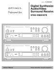
Analogic Filter Box
1.1 Analogic FIlter Box user interface
2.1.1
Introduction
The Analogic Filter Box sandwiches a rich and meaty distortion unit between two hearty analog-style filters to create a sound-shaping tool for every appetite. Juicy modulation is also provided on the side: An envelope, LFO, and envelope follower can be freely routed to the most
important filter and distortion parameters. Analogic Filter Box can handle everything from fat
disco-loop tweaking to full-on mangling of any sound source imaginable.
2.1.2
Structure and Signal Flow
The signal is routed from input to Filter 1, to the Distortion, to Filter 2, and then out.
REAKTOR FACTORY LIBRARY - Manual - 18
Effects
Analogic Filter Box
Both filters offer multiple operation modes. For the first filter, you can choose between Lowpass, Highpass, Bandpass, Peak EQ, and Notch filters, with a choice of a 12 or 24 dB/octave
slope per filter type. The second filter is designed for shaping the sound after the distortion, so
it offers four different lowpass filters, three bandpass filters, and a bandpass/lowpass combo.
Both filters were very carefully designed to produce warm, analog sounds even at extreme resonance and cutoff settings.
Beside the normal cutoff frequency control available in both filters, Filter 1 also provides fast
modulation of its frequency by an additional oscillator (which can itself be modulated by the
LFO, envelope, or envelope follower!).
The Distortion section between the two multimode filters also features multiple modes of operation. While the clipper mode provides a relatively harsh distortion sound and the saturator
mode results in warm overdrive, the several wrapping modes (marked by the name of the waveform used for wrapping) produce unique sounds from subtle to extreme.
An additional quantize mode converts the incoming signal into a step waveform, for familiar
bit-reduction effects to mimic the character of vintage samplers, for instance. A visual display
of the distortion function helps to see what's going on inside.
2.1.3
Modulation
Analogic Filter offers six modulation sources (A built-in LFO, envelope follower, enveloper,
MIDI note pitch, modulation wheel, and pitch bend wheel). The modulation sources and the
flexible matrix signal routing system at the bottom of this effect transforms it into an incredibly
powerful machine.
The modulation signal routing system provides a source selector for each parameter to be
modified; among those modifiable parameters are the cutoff frequencies and resonance settings of both filters and the distortion amount and symmetry control of the distortion section.
In addition to gate information from MIDI note-on events that can even be used to trigger the
filter, you can also use the pitch and mod wheels as modulation sources.
An internal LFO, envelope follower, and auto-trigger envelope can add movement to the sound
without the need any external MIDI controllers. The LFO offers different waveforms and can also be synchronized to the global tempo or MIDI clock (the small Unit knob syncs the LFO to
MIDI clock and sets the musical note-units that are shown under Freq). The Envelope Follower
calculates its modulation amount from the incoming signal: At high levels there is a high modulation level, and at low levels it's low. The Interval knob controls the response time to fast
REAKTOR FACTORY LIBRARY - Manual - 19
Effects
Anima
level changes. Use the cutoff controls of the internal highpass and lowpass filters to select a
specific frequency band of the incoming signal to trigger the envelope follower. The Envelope
is a standard attack-decay-sustainrelease envelope generator, triggered by MIDI note on events.
However, an additional auto-trigger feature allows it to be triggered by the incoming audio, settable with the Tresh slider.
It's even possible to combine any two MIDI controllers to make one dependent on the other for instance, to have the amount of LFO modulation dependent on MIDI pitch. You can define
custom mix modulation combinations in the Define Mix 1 and 2 areas as the bottom of the
instrument.
* You can play a sound through the built-in loop-player, through the realtime audio inputs, or
you can process audio in realtime by using Reaktor as an effect plugin. Please check your Reaktor or Reaktor Session user's guide for helpful information.
2.2
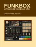
Anima
2.1 Anima user interface
Introduction
Anima is a polyphony-dependent filter bank, animated by an LFO that can produce complex
wave effects.
Input
<Level> Sets the input level, in dB. The meters show the post-fader input level.
REAKTOR FACTORY LIBRARY - Manual - 20
Effects
Anima
Filters
A single bandpass filter corresponds to every voice of polyphony. All of the filters are controlled
together, in the main XY display.
• <Y->Wdth> If ON, the Y coordinate of the Xy controller in the center of this panel modulates the width of the frequency band that is covered by the bandpass filters. If off, the Y
coordinate modulates the phase offset or starting point of the wave that determines the
amplitude of the bands. The "missing" parameter can be set with the "Wdth/Phse" knob.
• <Keyb> If ON, incoming midi notes shift the cutoff frequencies of the bandpass filters.
Note that the actual cutoff frequency as set by MIDI notes is not displayed in the XY panel.
• <Wdth/Phse> Width / Phase control. If the "Y-Wdth" button is off this knob controls the
width of the frequency band that is covered by the bandpass filters in semitones. If the
"Y-Wdth" button is on it controls the phase offset or starting point of the wave that determines the amplitude of the bandpass filters. Values between 0 and 1 set the phase between 0 and 360 degrees.
• <Waves> Sets the number of cycles of the wave that determines the amplitude of the
bandpass filters.
• <Resonance> Sets the resonance of the bandpass filters in dB. The amplification is compensated internally so the resonance controls only the narrowness of the bandpass filters.
• <Drive> Sets the amplification before the distortion unit. The amplification is compensated internally so it controls the amount of distortion.
• <XY Panel> The XY panel shows a graphical representation of the amplitude and frequency of all bandpass filters.
◦ Display: X->frequency of the filters
◦ Display: Y->amplitude of the filters
◦ Controller: X->center of the frequency range that is covered by the bandpass filters.
◦ Controller: Y->either the width of the frequency range or the phase offset of the wave
that determines the amplitude of the bandpass filters (depends on the "Y->width" button on the left).
REAKTOR FACTORY LIBRARY - Manual - 21
Effects
Anima
LFO
• <Sync> If ON, the LFO is synced to the global clock. Its length is then set in 16th notes.
The global clock can be started and stopped by the corresponding buttons in Reaktor’s
toolbox. If Reaktor is used as a plug in the clock of the host is used.
• <LFO Cycle> Sets the cycle length of the low frequency oscillator (LFO). The LFO modulates the phase offset of the wave that determines the amplitude of the bandpass filters.
If the "Snyc" button is on the length are set in 16th notes. If off the length is set in milliseconds.
• <Sine> Toggles the waveform of the LFO from triangle to sine wave.
• <Ampl> Sets the amplitude of the LFO.
• <Asym> Sets the amount of asymmetry of the LFO. E.g. a triangle waveform turns in a
sawtooth with a rising slope if the knob is turned fully clockwise. Counter clockwise it
turns into a sawtooth with a falling slope. In the center it remains a triangle waveform.
Output
• <Level> Sets the output level, in dB. The meters show the post-fader output level.
• <D/W>Dry / Wet control. It crossfades between the incoming signal (fully left) and the
processed signal (fully right).
• <Byps> Bypass switch which turns the effect off. When off, the CPU is no longer used.
REAKTOR FACTORY LIBRARY - Manual - 22
Effects
Banaan Electrique
2.3
Banaan Electrique
1.2 Banaan Electrique user interface
2.3.1
Introduction
Banaan Electrique is a sophisticated guitar and bass amp simulator with built in effects. It's
like having a pedal board full of vintage pedals and a vintage amp, with the added advantages
of not needing to cable anything together or risk electrocuting yourself by running too much
REAKTOR FACTORY LIBRARY - Manual - 23
Effects
Banaan Electrique
current through the amp. You can still get shocked by its lush sound, however. Naturally, Banaan is happy to eat whatever types of sounds you feed it, whether they're vocals, drum loops,
synths, or scallops.
2.3.2
Getting Started
Banaan Electrique was designed to be so easy that even guitar players can use it! Just play
some audio through it and let a rip.* Check out the presets to see the variety of tones that Banaan can achieve.
2.3.3
Structure and Signal Flow
The audio runs through Banaan Electrique linearly:
Input > mono gate > 3-band EQ > Compressor 1 > Amp Simulator > Phaser > Rotor > Dual
Delay > Reverb > Compressor 2
The incoming signal is converted to mono, amplified, gated, equalized and compressed to control the input's amplitude level and to enhance those sounds wanted to be in the recording,
getting rid of any unwanted noise. Then, a guitar amplifier is simulated, including distortion,
overdrive and filtering. Its output signal is sent to a rotor module, placing the mono sound in
the stereo field dynamically. This signal is then routed to a phaser effect and, afterwards, to a
stereo echo unit whose delay times can be synced to master tempo or MIDI clock. A high-quality reverb enhances the spatial sound once more, feeding its output into the final compressor.
Not all modules have to be active at the same time - in fact, it's a good idea to turn off any
modules that you're not using to save CPU. You can turn modules on and off with their respective Power buttons.
* You can play a sound through the built-in loop-player, through the realtime audio inputs, or
you can process audio in realtime by using Reaktor as an effect plugin. Please check your Reaktor or Reaktor Session user's guide for helpful information.
REAKTOR FACTORY LIBRARY - Manual - 24
Effects
Classic Vocoder
2.4
Classic Vocoder
1.3 Classic Vocoder user interface
2.4.1
Introduction
The Classic Vocoder was designed to faithfully emulate the well-known tones of singing robots
made popular in the seventies. The instrument combines a vocoding engine, a vintage-type
synthesizer, and a four-band dynamics processor for a warm, smooth sound.
2.4.2
Quick Start
The audio input is vocoded with the built-in synthesizer. Play some audio into the vocoder.*
You don't have to sing into it - the Classic Vocoder also gives great results with drum loops or
other sounds.
2.4.3
Structure and Signal Flow
Audio input 1 is the modulator, and is vocoded with the Classic 2-VCO synth, which is the carrier. The entire signal flow is mono. If you are using a stereo signal, only the left channel will
be used. The output of the vocoder is fed into the four-band normalizer to smooth-out the
sound and remove any uncomfortable signal peaks that could come with vocal sibilants or
drum transients.
REAKTOR FACTORY LIBRARY - Manual - 25
Effects
Classic Vocoder
2.4.4
The Vocoding Engine
Sonically, Vocoding uses the characteristics of one sound to control another. To achieve the
popular robotic-singing effect, a voice (technically called the modulator) is vocoded with a constant sound, such as a synth or string sound (the carrier). The frequency content of the voice is
split up into many different bands - the number of bands has an obvious impact on the sound,
with fewer bands leading to more synthetic voices, and higher bands make the voice easier to
understand. You can adjust the number of voices of the vocoder instrument to change how
many bands are used. Up to 128 voices (bands) are possible. All changes in number of bands
are immediately shown in the graphical display.
The amplitude of each frequency band of the voice is linked to the frequency bands in the
string or synth sound. The re-shaped bands of the carrier signal are mixed together, providing
the output signal of the vocoder.
If you're interested in vocoding, you may also want to do check out another NI product - the
VOKATOR. The VOKATOR features vocoding up to 1024 bands, a built in synthesizer and
granular sampler, and many high-end vocoding features. www.ni-vokator.com.
* You can play a sound through the built-in loop-player, through the realtime audio inputs, or
you can process audio in realtime by using Reaktor as an effect plugin. Please check your Reaktor or Reaktor Session user's guide for helpful information.
2.5
Cyan
3.2 Cyan user interface
REAKTOR FACTORY LIBRARY - Manual - 26
Effects
Cyan
Introduction
Like a traditional Chorus effect, Cyan uses a bank of modulated-delay units to add width,
depth and richness to the input signal. And due to painstaking attention to detail in the design
process, Cyan can reproduce classic chorus-type sounds with the finest sound quality. However, Cyan is far more than just a high-quality chorus unit. Indeed, due to its advanced features
such as tempo-synchronisation and extended delay modulation control, Cyan offers many new
and exciting sound-shaping possibilities.
Details
The effect's architecture consists of up to six independent stereo delay lines (see sections Distance, Intensity and LFO) that are fed with the incoming audio signal (see Input). Optionally,
the delay lines' output can be routed again to their input to establish an additional feedback
circuit (Feedback). After summing the delay lines' signal the sound is routed to a saturation
unit and an equalizer to dynamically and harmonically re-shape the chorused signal (Saturation and Equalizer). Finally, the signal is mixed with the unprocessed one and sent to the output (Mix Automation, Additional Mix and Output).
Section
Function
Power and Input
These two sections control whether the chorus is switched on or off and which signal
is used as input: The complete stereo signal, the left channel alone, or a mono mix of
both.
Distance, Intensity,
The Delay knob on the other hand adjusts the delay times offset, thus controlling the
phase variation applied to the chorused signal in respect to the unprocessed signal.
The Spread control additionally changes this offset slightly for each LFO independently to enhance this effect. The Intensity knob mainly controls the sound of the chorus:
It determines the amount by which the delay times vary.
and Feedback
After passing through the delay units, the signal is routed to the Feedback section
where it can be filtered (using the Colour knob to control the filter's frequency), and is
then mixed with dry signal. The FB amount knob is bi-polar: At the right there is normal feedback, at the left the feedback signal's phase is inverted; at mid position the
feedback is turned off.
REAKTOR FACTORY LIBRARY - Manual - 27
Effects
Cyan
Section
Function
LFO
Waveform and LFO determine the shape and number of low frequency oscillators.
Rate controls how fast the delay times are modulated by the low frequency oscillators.
This speed is displayed either in Hertz or, if MIDI Sync is enabled, in rhythmical values.
MIDI Sync is only available if Freq. Mode is set to ‘Phaselocked’, meaning that the
phase of the LFOs is linked to each other. If it is set to ‘Freerun’, the LFOs' phase can
be spread (like the delay time offset) by the Ph.Spread knob.
Ph.Shift controls the phase to which the oscillators are reset at synchronization events
that can be specified with the LFO Reset switch; the button below this menu can be
used to manually synchronize the oscillators.
Saturator and Equalizer
After the chorus section itself the audio signal can be saturated and equalized.
Mix automation and
output
Finally, the chorused signal is mixed with the unprocessed sound, defined by the Dry/
Wet balance knob position. Mix balance can also be automated by a ramp generator,
the speed of which is adjustable by the Speed knob. The ramp generator trigger source
can be selected at the left of the Att knob.
The small switch below the main Dry/Wet knob mutes the unprocessed audio, effectively converting the Dry/Wet knob into an amplifier for the processed signal. This is
especially useful when using Cyan as a send effect.
Tremolo enables amplitude modulation, synchronized to the delay time modulation.
The Stereo knob controls the spread of the audio within the stereo panorama.
REAKTOR FACTORY LIBRARY - Manual - 28
Effects
Echomania
2.6
Echomania
1.4 Echomania user interface
2.6.1
Introduction
Echomania is an advanced and spectacular-sounding delay box that excels at tight, temposynced rhythms. It includes two LFOs to to modulate the delay time and built-in EQ. The delay
time is handily synced to the global MIDI clock, for creating stretchy rhythmic effects. A drive
and noise circuit combined with a feedback offset control recreate vintage sounds. Get dubbing!
2.6.2
Quick Start
Play some audio through Echomania.* Flip through the snapshots and discover the gritty (or
crystalline) depths of Tapedelay.
2.6.3
Structure and Signal Flow
The delay time is set in 16th note increments, synced to the global MIDI clock. The Unit and
Divisor windows, to the right of the Time control, allow you to fine tune the beat division and
create different rhythmic feels—to be precise, the enumerator divided by the denominator
scales the delay time fraction.
REAKTOR FACTORY LIBRARY - Manual - 29
Effects
Echomania
There is also an LFO, with blendable sine/triangle/square/slow random waveshapes that is
hardwired to modify delay time. You can set the amount of time modulation with the Amount
knob. The Freq knob controls the rate of the LFO in 16th notes. The Unit knob divides the
speed of the global clock by the Unit amount. For example, if the Unit knob is set to "6", then
the LFO Freq amount will be in 16th notes. The Width control morphs between sine and pulselike, or, if the Tri button is engaged, triangle and saw tooth waveshapes. The starting phase of
the LFO can be adjusted positively or negatively using the Phse knob. If you engage the Snc
button, the right-side LFO can be phase-offset from the left side by the amount set with the
Right knob. This can create a variety of woozy stereo spinning and phasing effects.
The EQ module processes the delayed signal. It is essentially a parametric EQ that contains an
LFO identical to the one in the Delay module. You can create synchronized filter sweeps, fizzing hi-frequency delay tails, and all manner of dubby effects by boosting and modulating select frequency bands. The Eq Res control lets you dial in the peak width of the frequency,
while EQ Boost lets you crank it up.
Tapedelay's Feedback module provides an offset control, labeled FB > 1, which boosts and
shapes the feedbacl signal, making it seem to get louder and louder (but without degenerating
into uncontrollable noise).
The Mixer lets you add a tape saturation-like Dist Drive effect and Noise to give everything that
just-pulled-out-of-the-closet feeling.
The Dry Wet section allows you to balance the amount of dry and delayed signal. You can also
use the Tap buttons to select whether the delay tap comes before or after the saturation/noise
circuit.
* You can play a sound through the built-in loop-player, through the realtime audio inputs, or
you can process audio in realtime by using Reaktor as an effect plugin. Please check your Reaktor or Reaktor Session user's guide for helpful information.
REAKTOR FACTORY LIBRARY - Manual - 30
Effects
EnFX
2.7
EnFX
2.3 EnFX user interface
Introduction
EnFX consists of three separate effects: an envelope-follower filter, distortion, and delay. Even
though the effects are together in one ensemble, they can also be used independently. The ensemble is routed in series: Filter -> Distortion -> Delay. Each effect features a identical Input,
Envelope Follower, and Output sections. These sections will be explained first:
REAKTOR FACTORY LIBRARY - Manual - 31
Effects
EnFX
Input
<Level> Sets the input level, in dB. The meters show the post-fader input level.
Envelope Follower
An envelope follower isn t a dog that chases the postman. Instead, an envelope follower listens
to the incoming audio, and when the level of the audio exceeds a certain threshold, then a
simple HR (hold/release) envelope is triggered. This envelope can control different parameters,
depending on the effect. The result is an effect that wraps itself around the incoming audio for
an organic, natural sound.
• <On> Switches the envelope follower on or off to save cpu power.
• <Hold>, <Release> Set the hold and release values of a HR-envelope that is triggered by
a rising of the input level. It shapes the output of the peak detector. Lower values, i. e.
shorter hold and release times, result in a sharper response to level decays.
• <Mono> Switches between stereo mode (off) and mono mode (on). Use mono mode for a
more stable envelope. In stereo mode, the two incoming channels are processed seperately -a separate envelope of the left and the right channel is generated. In mono mode, both
channels are mixed together before extracting the envelope. ATTENTION: If a mono input
source is connected to both effect input channels, be careful using this switch: The envelope is already mono, so there’s no additional benefit; instead, by mixing, i. e. adding
both channels the signal is amplified and exceeds the normal range.
• <PkRel> Sets the release time of the amplitude peak detector. Lower values at the left
result in more sensitivity to smaller peaks (e. g. HiHats), higher values instead only detect
really high peaks like bass drums etc.
• <Smth> Sets the amount of smoothing of the shaping envelope. Higher values result in a
more smoothed signal following the envelope of the incoming signal.
• <Envelope Meter L & R> Show the output of the envelope follower section.
2.7.1
EnFX Delay 1.3
At the center the EnFX delay is a delay whose time is modulated by an envelope follower. It s
useful for very long delays due to internal feedback enhancements as well as for unique pitch
shifting. See the envelope follower info above for information about the envelope follower section.
REAKTOR FACTORY LIBRARY - Manual - 32
Effects
EnFX
• <Left> Sets the delay time of the left audio channel. The display below shows the delay
time in 16th notes according to the midi tempo. Internally, the linear output of the knob
is processed by a function mapping it onto a grid to allow very short decays as well as very
long decays. The grid also performs triplet division of the time (0.3333, 0.1667, 0.0833
etc).
• <-E+> Sets the amount of modulation and its polarity applied to the delay time of the left
channel. Turn to the right for a longer delay times at high envelope follower signals, turn
to the left for shorter delay times at high envlope follower signals. Use mid position to
switch the modulation off.
• <Right> Sest the delay time of the right audio channel.
• <-E+> Sets the amount of modulation and its polarity applied to the delay time of the left
channel. Turn to the right for a longer delay times at high envelope follower signals, turn
to the left for shorter delay times at high envlope follower signals. Use mid position to
switch the modulation off.
• <LP> Sets the cutoff freqeuncy of a lowpass filtering performed to the feedback signal.
• <HP> Sets the cutoff freqeuncy of a highpass filtering performed to the feedback signal.
• <Lift> Sets the maximum level lifting. Turn right to amplify very silent signals in the feedback tail, turn left to amplify only the louder signals. Use it to make very long and damped feedbacks audible.
• <Smth> Sets the amount of smoothing in the level lifting algotithm. Turn to the left for
smooth transistions, turn to the right for sharper and faster response to level changes.
• <Swap> Sets the amount and mode of channel swapping of the feedback signal. Turn to
the left for no swapping, i. e. the left channel remains the left one, the right channel the
right one. Turn to mid position for mono processing, i. e. both signals occur in both channels. Turn to the right for crossfading, i. e. the left channel signal becomes the right
channel signal and vice versa.
• <Fb> Sets the amount of feedback in the delay. More feedback leads to a decay with
more repeats.
• <Dry/Wet> Crossfades between the dry (unprocessed) signal at the left and the wet (processed) delayed audio at the right.
REAKTOR FACTORY LIBRARY - Manual - 33
Effects
EnFX
• <-E+> Sets the amount of modulation and its polarity applied to the dry/wet balance.
Turn to the right for a more wet signal at high envelope follower signals, turn to the left
for a more dry signal at high envlope follower signals. Use mid position to switch the modulation off. The yellow meter displays the actual value of the parameter modulated by —E
+.
Output
• <Level> Sets the output level, in dB. The meters show the post-fader output level.
• <D/W>Dry / Wet control. It crossfades between the incoming signal (fully left) and the
processed signal (fully right).
<Byps> Bypass switch which turns the effect off. When off, the CPU is no longer used.
2.7.2
EnFX Distortion 1.3
EnFX Distortion is a overdrive effect with a pre- and a post-distortion equalization filter whose
center freqeuncies are controlled by an envelope follower. Usefull for all kinds of overdive effects, but can also be used for guitar wahwah etc. due to the responce to level changes of the
incoming signal. In the distorion section, the left knobs belong to the "push" filter that modifies the signal before the distortion; the right knobs belong to the "pop" post-distortion equalizer. See the envelope follower info above for information about the envelope follower section.
• <rEs L& R> Set the amount of resonance of the peak eq filters.
• <Push> Sets the freqeuncy of the pre-distortion peak equalizer
• <Res> Sets the resonance of the pre-distortion peak equalizer.
• <-E+> Sets the amount of modulation and its polarity applied to the frequency of the predistortion peak equalizer. Turn to the right for a higher frequency at high envelope follower signals, turn to the left for lower freqeuncies at high envlope follower signals. Use mid
position to switch the modulation off. The yellow meter displays the actual value of the
parameter modulated by —E+.
• <Dist>Sets the amount of distortion. On high distortion levels the signal might tend to
fade. Increase the drive value to fade it back in.
• <Boost> Sets the amount of amplification performed to the freqeuncies set by the Push
and Pop knobs.
REAKTOR FACTORY LIBRARY - Manual - 34
Effects
EnFX
• <Drive> Sets the amount of overdrive amplification.
• <Pop>Sets the freqeuncy of the post-distortion peak equalizer.
• <-E+> Sets the amount of modulation and its polarity applied to the frequency of the
post-distortion peak equalizer Turn to the right for a higher frequency at high envelope
follower signals, turn to the left for lower freqeuncies at high envlope follower signals. Use
mid position to switch the modulation off. The yellow meter displays the actual value of
the parameter modulated by —E+.
• <Res> Sets the resonance of the post-distortion peak equalizer.
• <Dry/Wet> Crossfades between the dry (unprocessed) signal at the left and the wet (processed) distorted audio at the right.
• <-E+> Sets the amount of modulation and its polarity applied to the dry/wet balance.
Turn to the right for a more wet signal at high envelope follower signals, turn to the left
for a more dry signal at high envlope follower signals. Use mid position to switch the modulation off. The yellow meter displays the actual value of the parameter modulated by —E
+.
2.7.3
EnFX Filter 1.3
An envelope follower filter is traditionally used to create ªwah wah sounds, but the flexiblity of
EnFX s design makes much more experimental sounds possible. See the envelope follower info
above for information about the envelope follower section.
• <rate> Sets the rate of a slow random generator. The value displayed below shows the
time in milliseconds that goes by before another random event is generated.
• <Depth> Sets the depth of modulation, i. e. the amount by which the envelope follower
signal is modulated by the slow random generator. Turn right for more modulation.
• <Res> Set the amount of resonance, the left knob at the lower cutoff freqeuncy, the right
one at the higher freqeuncy. (See also <cut/pass>.)
• <Filter cutoff freq meter> Show the current cutoff freqeuncy. Here you can see also the
effect of modulation by the envelope follower and the slow random generator. Left represents a low freqeuncy, right a high freqeuncy. The meter on the left below the <LOW>
knob displays the frequency used in the lower filter, while the other one displays the freqeuncy of the higher filter. (See also <cut/pass>.)
REAKTOR FACTORY LIBRARY - Manual - 35
Effects
EnFX
• <-E+> Set the amount of modulation of the filter cutoff freqeuncies by the envelope follower ) whose signal before was modulated by the slow random generator). Turn left to
make the filter freqeuncy be reduced on high incoming envelopes, turn right for the opposite, i. e. high envelope signals increase the cutoff freqeuncy. The left knob modifies the
lower cutoff freqeuncy, the right one the higher freqeuncy. (See also <Cut/Pass>.)
• <Low> Sets the lower cutoff freqeuncy. (See also <Cut/Pass>.)
• <High> Sets the higher cutoff freqeuncy. (See also <Cut/Pass>.)
• <Cut/Pass> Crossfades between cut mode (left position) and pass mode (right position).
In cut mode, all freqeuncies below the lower freqeuncy set by <Low> and above the higher freqeuncy set by <High> are cut off, resulting in a bandpass filter whose boundaries
are specified by the lower and higher freqeuncy. In pass mode, all freqeuncies below the
lower freqeuncy set by <Low> and above the higher freqeuncy set by <High> are passed
through, resulting in a noth filter whose boundaries are specified by the lower and higher
freqeuncy.
REAKTOR FACTORY LIBRARY - Manual - 36
Effects
Fast FX
2.8
Fast FX
3.3 FAST FX user interface
REAKTOR FACTORY LIBRARY - Manual - 37
Effects
Fast FX
Introduction
Fast FX is a set of 6 different effects: Freeze, zZZzZ, Slicemanipulator, Gate, Delay and Filter.
These effects can be chained in a variety of ways offering a large range of sounddesign possibilities. However, Fast FX’s speciality is live performance. Not only are all controls designed to
be tweaked in real-time, but Fast FX features a special ‘live’ snapshot system – enabling any of
the 256 states to be instantly recalled via simple keyboard strokes. This ability to instantly
switch between sets is what really brings Fast FX to life.
Quick Start
The most important thing to note is that Fast FX does not use the standard REAKTOR snapshot
system. Instead it uses a special 256-slot system operated by the panel and computer / MIDI
keystrokes. The 256 snapshots are made up of 32 x 8 slot banks. Select bank by the using the
32-step Program Selector slider at the bottom of the panel, and select the slot by using the
QWERTUI Selector above.
When Flow is enabled, selecting a new bank or slot automatically loads the preset. Press Write
to save the current ensemble state to the selected bank/slot.
Fast FX is supplied with a Loop-player for a useful sound source in REAKTOR standalone
mode, but it can also process live input (e.g. when used as a plug-in in a host sequencer.) The
Loopplayer input is selected by default, but to enable the Live input press the In 1/2 button in
the Input section. Fast FX will now process the audio input from REAKTOR audio-in channels
1 and 2.
Global Controls
Section
Function
Input
Fast FX has two pairs of stereo inputs. The first pair of inputs are connected to the
Loopplayer instrument, whereas the second pair are connected to REAKTOR’s audioin ports. Enable the 1/2 button to select the second pair (i.e. for use with live audio
input, or when using Fast FX as a plug-in inside a host application).
Level and Mute control the input level.
Junction
This section allows configuration of the signal flow order between the 6 effects. Eight
possibilities are available in the drop-down menu.
REAKTOR FACTORY LIBRARY - Manual - 38
Effects
Fast FX
Section
Function
Output
Level and Mute control the output level. All effects can be bypassed simultaneously
with the Bypass button.
Mix
The mix section controls the overall mix between the dry input signal and the wet,
post FX signal. The mix is defined separately for low and high frequencies with the
Low and High knobs. Link synchronises the two knobs.
REAKTOR FACTORY LIBRARY - Manual - 39
Effects
Fast FX
The Effects
Section
Function
Freeze
The Freeze effect makes looping and scratching sounds.
Loop sets the loop length in musical time, from 1/16th to 4/1 (1 bar = 16/16th’s).
Spin determines how the loop length changes when the effect is enabled. A setting of
1/32 will result in a loop length that is 32 times shorter, a setting of 32/1 will result
in a loop length 32 times longer.
Spin Time determines the speed of loop length changing, and Jtr sets the delay time
jitter – the amount of slow, random variation.
zZzzZZ
This effect slices incoming sound into grains, and then slides the pitch, so that the
pitch of each successive grain is either decreasing or falling compared to the previous.
Slice A and Slice B set the length of first and second slices respectively, in 16th steps.
Length sets the grain length in milliseconds. Below, the knob labelled Mod sets the
amount of grain length modulation. Slide+ controls pitch slide, and the Mod knob below determines the amount of pitch modulation.
For both Length and Pitch modulation, a collection of pseudorandom, MIDI clock
synchronised patterns are used as the modulation source. The Rnd XY field is used to
select the current pseudo-random pattern (each pixel represents one of the 1920
available patterns).
Asym sets the grain size asymmetry between the left and right channels. Decay controls the dry signal decay time, the envelope is retriggered with each new slice (i.e. at
intervals according to the Slice A and Slice B controls).
REAKTOR FACTORY LIBRARY - Manual - 40
Effects
Fast FX
Section
Function
Slice Manipulator
This effect also slices the incoming sound, and then shifts the position and playback
direction of the slices.
Slice A and Slice B set the length of first and second slices respectively, in 16th steps.
The two slicers work on a rotating basis, so therefore the slice lengths alternate between the two settings.
The SncVar enables a mathematical formula to automatically rearrange and vary the
slices in time. Set to zero for no variation.
Rev A and Rev B enable reverse playback of the first and second slices.
Gate
This section features a 16-step sequencer that modulates the amplitude of the incoming signal. The horizontal slider above the sequencer display selects one of the 20
available patterns for the sequencer, and the lower horizontal slider sets the sequencer clock speed. The preset sequence can be varied by reducing the loop length with
the Length knob, or by varying the playback position with the PosVar knob. This control
applies one of 16 variation patterns to the sequence playback order.
Gate determines the length of the open gate, as a proportion of a sequencer step. Release sets the time the gate takes to close.
REAKTOR FACTORY LIBRARY - Manual - 41
Effects
Fast FX
Section
Function
Delay
The section features a stereo delay line with a modulated filter in the feedback path.
Delay sets the delay time in 16th steps, Fbck sets the feedback amount and Asym sets
the delay time asymmetry between the left and right channels.
Filter sets the centre frequency of the feedback filter. The cutoff is also modulated a
beat-synced LFO, controlled by the central XY field and Speed knob. The XY X axis
sets the LFO phase; the Y axis sets the modulation depth; and the Speed knob sets
the speed (cycles per bar).
Smth controls the speed that delay time changes (from the Delay / Asym knobs) are
applied, and also the crossfade speed of enabling/disabling the effect.
Filter
This section features a sequenced filter. The horizontal slider above the sequencer
display selects one of the 20 available patterns for the sequencer, and the lower horizontal slider sets the sequencer clock speed. Length sets the loop length of the sequencer. Mod defines how much the extent to which the sequencer modulates the filter cutoff.
Center and Reso set the filter cutoff and resonance respectively, and Width sets the filter width. Smth controls the speed that of changes to the cutoff frequency (from the
sequencer or the Center knob).
REAKTOR FACTORY LIBRARY - Manual - 42
Effects
Fast FX
Snapshot control
Section
Function
Q W E R TYU I
In Fast FX, the REAKTOR snapshot menu is not used for handling snapshots. Instead,
with live performance in mind, the snapshot handling is dealt with on the panel.
Fast FX has a total of 256 snapshot slots, represented by 32 x 8 slot programs. The
32 programs are selectable by the Program Selector at the bottom of the panel. Either
click on the selector itself, use the Prev and Next buttons, or press computer keys ‘L’
or ‘;’.
Within each program, the 8 sub-slots are selectable by the QWERTUI Selector. To select a slot, click on the selector, or press the associated computer keyboard key (i.e.
Q,W,E,R,T,Y,U,I) or MIDI note (60,62,64,65,67,69,71,72).
The total 256 slot data is stored in a large event table inside the structure. If you wish
to export snapshot files, simply save the table data by right clicking on the table display either beneath the QWERTYUI selector or the Program Selector.
Bookmark
The bookmark feature enables you to store your favourite presets numbers and quickly
access them by using the dropdown menu.
To set a bookmark to the current state, take a look at the POSITION display, then open
the Bookmark list properties, and create an entry there with a name of your choice,
and the value displayed in the position meter.
Flow and Write
When Flow is enabled, selecting a snapshot position (via either the QWERTUI or Program selector) automatically recalls the data. Disable this if you want to copy the current state to another slot (i.e. disable Flow, select the desired Slot and then press
Write).
Write writes the ensemble state to the current bank and QWERTUI slot.
REAKTOR FACTORY LIBRARY - Manual - 43
Effects
Fast FX
Loopplayer
Section
Function
Panel controls
This is an additional instrument for playing loops, it uses the REAKTOR Beatloop
module, and thus automatically stretches loops to the current tempo.
You can drop samples on the sampler window, or double click on it to open the REAKTOR map editor. Transpose should be set to 0 for all samples
Select the desired sample from the map using the Select knob. Loop Lng and Offset
and define the loop length, and position offset in 16th steps respectively. Pitch transposes the sample in semitones.
The Loopplayer has 16 different automatic variation patterns, these can be selected
with the Pos Variator knob.
Center and Reso set the filter cutoff and resonance respectively, and Width sets the filter width. The filter can be bypassed by pressing the Bps switch. Rnd Mrph determines
the amount to which a slow randomiser is applied to the filter cutoff.
Fit links sample pitch with time stretching, like a conventional sampler (i.e. the slower
the tempo, the lower the pitch).
Smooth controls the sampler grain smoothness, and Gain determines the output level.
Snapshot handling
The Loopplayer state is not saved in the Fast FX snapshot table, but pressing the Write
creates a snapshot in the Loopplayer instrument. Programs 1 to 16 are stored in bank
1 and programs 16 to 32 are stored in bank2. These are recalled when recalling snapshots on the Fast FX panel.
REAKTOR FACTORY LIBRARY - Manual - 44
Effects
FlatBlaster 2
2.9
FlatBlaster 2
4.1 The Flat Blaster 2 user interface
2.9.1
Introduction
The great final-stage mastering tool FlatBlaster 2 has been rebuilt using the new REAKTOR
Core features. This patch combines four frequency-specific compressors with a full-spectrum
peak-limiter to produce a high-end package for your multiband dynamics shaping needs. As it
does not introduce any delay it is not limited to mastering use but can also be applied on a per
channel basis. The controls might appear intimidating at first glance, but are actually straightforward when you examine the signal chain. The separately compressed bands get mixed together and then processed by a full-band peak limiter. Please note that the master bypass for
the complete patch is situated to the left above the X Over section.
REAKTOR FACTORY LIBRARY - Manual - 45
Effects
FlatBlaster 2
2.9.2
What’s New in 2.0.2?
Version 2.0.2 of Flatblaster 2 sports the following improvements:
• Lookaheads in compressors and limiter
• Smoother behaviour of envelope the followers
• Knee instead of saturation in the limiter
• Overall CPU consumption reduced
2.9.3
Multi-band Compressor
After the input stage the signal gets split into four independent frequency bands as defined by
the X Over section. Each frequency band gets processed by independent, identical compressors and can be independently muted, soloed and bypassed. Separate saturators for each band
make it possible, for example, to add punch and bite to the mids without affecting clarity in
the lower registers.
Section
Control
Function
Input
Input
Trims the input gain to prevent overload.
Bypass
Bypasses the complete effect. This is the master bypass switching off all
compressors and the Limiter.
High
Sets the crossover frequency between the High and Mid High compressor
bands.
Mid
Sets the crossover frequency between the Mid High and Mid Low compressor bands.
Low
Sets the crossover frequency between the Mid Low and Low compressor
bands.
X-Over
High, Mid High, Stereo
Mid Low and
Low CompresTresh
sors
Ratio
Sets stereo width of the frequency band. 0 is mono, 1 is original stereo,
2 is extra stereo.
Sets the point at which the compressor will begin to work (in db). Levels
below this threshold remain unprocessed.
Adjusts the ratio of the input level to the output level after compression.
REAKTOR FACTORY LIBRARY - Manual - 46
Effects
FlatBlaster 2
Section
Control
Function
Knee
This parameter adjusts how gradually the full amount of compression is
introduced. Think of it as a slope control for the attack time.
Sat
Drives the band into saturation.
Link
Activates stereo linking of the two input channels. When active, the compressor takes the max of the left and right
peak levels and uses it for both channels. This preserves a clean stereo
image and is lighter on CPU cycles.
2.9.4
Att
This dial adjusts the attack time. It is the time the compressor takes to
react to an above-threshold signal.
Rel
With this control you set the release time. This is the time the compressor takes to return the signal to normal when it falls below the compression threshold.
Out Gain
Sets the amount of amplification applied to the compressed signal of the
specific band before it gets mixed with the other bands.
Bypass
Bypasses the compressor for the respective band.
Mute
Turns the sound of the respective band off.
Solo
Turns all other bands off, leaving only the signal of the soloed band. Use
it to fine tune single compressor bands.
Full-band Peak Limiter
The peak limiter affects the full band signal. For clean mastering purposes we recommend a
limiter threshold setting of about -3 to -4 db and a peak setting at 0db. Should pumping effects be desired, adjust the threshold to more extreme values.
Control
Function
Thr
Adjusts the threshold of the limiter. Levels above this value get processed.
Peak
Adjusts the hard limit of the signal. No signal will exceed this limit.
Rel
This adjusts the release time. It is the time the limiter takes to return the signal to
normal when it falls below the limiting threshold.
Soft / Hard
Balances between soft saturation and hard clipping of the above peak signal.
REAKTOR FACTORY LIBRARY - Manual - 47
Effects
Flatblaster
Control
Function
Compare
Controls the amplification of the uncompressed signal if Bypass is active. If you want
compression without amplification set it to 0 and make sure there is no change in level when toggling the Bypass button.
Link
Activates stereo linking of the two input channels.
Bypass
Bypasses the Full Band Peak Limiter only, leaving the 4 compressors active.
2.10
Flatblaster
1.5 Flatblaster user interface
2.10.1
Introduction
Flatblaster is a high-end finalizing and multiband dynamic shaping tool. Flatblaster combines
four frequency-specific compressors with a full-spectrum peak-limiter. It is an excellent finalstep mastering plug-in, but it can also be used while mixing since it doesn't introduce any de-
REAKTOR FACTORY LIBRARY - Manual - 48
Effects
Flatblaster
lay to the signal. Each of the compressors has a saturator, so you could saturate just the uppermid frequencies, for instance, without muddying the bass. It also makes an excellent de-esser
and sibilant reducer.
2.10.2
Quick Start
Even though Flatblaster gives control over many sound-shaping parameters, there's no need to
be intimidated by its complexity. A full range of presets shows off its capabilities and gives
good starting points for tweaking the effect for your sound. Simply play some audio through
Flatblaster* and step throught the presets. Try experimenting with muting, soloing, and bypassing each individual band so you can carefully hear what the 'blaster's doing. Be careful
when adjusting the saturation of each band! The sound can potentially get very loud if you
don't first reduce the make-up gain (the knob labeled Gain to the right of the Sat knob).
2.10.3
Structure and Signal Flow
The input signal is divided into four bands - the three crossover frequencies are adjustable independently. Each frequency band is processed by an independent, identical compressor.
Each band can be muted, soloed, and bypassed (no compression). The signal is summed before going through a full-band peak limiter, which can also be independently bypassed. The
master bypass for the effect is located to the right of the input meters, above the crossover settings.
2.10.4
Frequency-Specific Compressor
Each of the four compressors are absolutely identical. In fact, they have to be! If they weren't,
then unwanted phase shifts could creep in. Each compressor gives control over saturation, saturation makeup gain, threshold, compression ratio, adjustable knee, attack, release, and output makeup gain. Note that the Ratio has to be higher than 0 for the compressor to have any
effect - at a Ration of 1 (maximum), the compressor acts as a limiter. The red meters show the
amount of peak reduction. The Attack and Release knobs control how the compressor responds
to transient signals.
REAKTOR FACTORY LIBRARY - Manual - 49
Effects
Flatblaster
2.10.5
Full-Band Peak Limiter
The peak limiter affects the full frequency range of the audio, after each of the four frequency
bands has been compressed separately. The Threshold slider controls when the peak limiter
will start working. With Threshold at 0, the peak limiter will have no effect. For mastering, it's
recommended to have the Threshold set to around -3 or -4 dB. Severe Threshold settings will
lead to pumping, which may or may not be desirable. The Attack and Release knobs control
how the peak limiter responds to transient signals. The final Peak slider sets the output level of
the signal. When Peak is set to its maximum 0 dB, then the audio will be as loud as possible.
There's really no reason to ever set Peak lower than this, unless you needed to ensure a certain
amount of headroom.
* You can play a sound through the built-in loop-player, through the realtime audio inputs, or
you can process audio in realtime by using Reaktor as an effect plugin. Please check your Reaktor or Reaktor Session user's guide for helpful information.
REAKTOR FACTORY LIBRARY - Manual - 50
Effects
Fusion Reflections
2.11
Fusion Reflections
1.6 Fusion Reflections user interface
2.11.1
Introduction
Fusion Reflections is a delay-based effect that can create early reflections, shimmering choruses, fluttering delays, and even ambient reverbs. Two distinct diffusion engines are chained together to create an extremely wide range of effects. Each finely-tuned diffusion engine consists
of four stereo modulation delays and an innovative graphical display that shows the actual delay time for each delay. Just five controls control the core parameters of each diffusion engine.
REAKTOR FACTORY LIBRARY - Manual - 51
Effects
Fusion Reflections
2.11.2
Quick Start
Play some audio through the effect* and select Preset 1 Long Decay Echo. This preset only
uses the Chor Fusion diffusion engine. Play with the Diff Dly knob - note how the graphic display constantly updates to show you the current delay times. Stop the incoming audio to listen
to the sound's decay. Play with Dly Mod and Speed to see what effect they have on the sound
and the graphic. Be sure to check out all the other presets to see how versatile this effect can
be!
2.11.3
Structure and Signal Flow
The sound passes through two diffusion engines serially. It's important to note that the two engines are similar but not identical - they each offer unique sound-shaping capabilities. The
first diffuser, Chor Fusion, is the simpler of the two and is designed for early reflections, choruses, and atmosphere. If offers a high and low shelf EQ, with a graphical display of the EQ
curve. The second diffusion engine, Echo Fusion, adds a feedback delay before the diffusion
delays. The diffusion delays in the Chor and Echo engines are identical. Echo Fusion is perfectly tailored to late reflections, long delays, and long reverbs. A highpass filter (HP) cuts the
low frequencies after the delay and before the diffusors, while a lowpass filter (LP) can reduce
the brightness at the last step. The input to the Echo Fusion engine can be switched between
the dry signal, and the signal coming out of Chor Fusion.
In the Mixer section the signals of Chor Fusion> and Echo Fusion are combined and mixed
with the dry signal. Each section can also be switched on or off to save CPU.
2.11.4
Diffusion Delays
Both the Chor and Echo Fusion engines contain identical diffusion delays. As mentioned
above, Echo fusion adds a single feeback delay before the diffusion delays, but the operation
of the diffusion delay section is identical per effect. Each diffusion delay consists of four stereo modulation delays and an innovative graphical display that shows the actual delay time of
each delay. The main delay time is controlled by the Diff Dly knob. The Dly Mod knob controls
the amount of delay time modulation by the internal LFOs. Speed controls the speed of the
LFO. Stereo sets the stereo spread of the delays, and Diffusion sets the inaccuracy of the delay
times. The sum effect of these five knobs is graphically shown in the display underneath,
where each "pendulum" represents the delay time of a single delay.
REAKTOR FACTORY LIBRARY - Manual - 52
Effects
Grainstates FX
* You can play a sound through the built-in loop-player, through the realtime audio inputs, or
you can process audio in realtime by using Reaktor as an effect plugin. Please check your Reaktor or Reaktor Session user's guide for helpful information.
2.12
Grainstates FX
1.7 Grainstates FX user interface
2.12.1
Introduction
Grainstates is a granular texture maker that works wonders for creating dense, breathing atmospheres. Taking advantage of Reaktor 4's grain cloud delay module, GrainStates lets you
create granular soundscapes in realtime. You can even freeze the live audio - imagine playing a
guitar into Grainstates, freezing the audio, then playing a counterpoint to the granular texture.
Eight scenes - each scene storing information about grain size, density, pitch, pitch spread,
and more - are sequentially recalled in sync with the master tempo. A dual-frequency delay
adds depth to the sound by letting you specify independent delay and feedback times for the
high and low frequencies.
Grainstates consists of two ensembles: GrainStatesFX and GrainStatesSP. GrainStatesFX is an
effect using the grain cloud delay that works on live input, while GrainStatesSP is centered
around the grain cloud sampler module. The FX ensemble has the advantages that you can
REAKTOR FACTORY LIBRARY - Manual - 53
Effects
Grainstates FX
easily process audio without loading anything into a sampler and you can freeze the incoming
audio stream - great for live performance! Since the sound passes through the ensemble, however, there's no way to save the sound data with the preset. GrainStatesSP stores the sample
with the preset so it can easily be recalled at a later time, but you must first load your sound
into the grain cloud sampler.
2.12.2
Quick Start
GrainStates FX: Start the system clock and run some audio through the ensemble.* You'll notice
a graphical representation of the sound "marching through" the granular buffer. To freeze the
buffer, press the Freeze button to the left of this graphical display. If you stop the system
clock, the sound will continue, but the scenes won't advance.
GrainStatesSP: Start the system clock and step through the presets. If you stop the system
clock, the sound will continue, but the scenes won't advance.
2.12.3
Structure and Signal Flow
At the heart of GrainStates is the granular grain cloud module. GrainStatesFX is based on two
(for true stereo operation) grain cloud delay modules, while GrainStatesSP is based on a single
grain cloud sampler module. Both the grain cloud delay and grain cloud sampler have identical
controls, with the grain cloud delay adding the ability to freeze the sound. All of GrainState's
controls (with the exception of the 2Band Delay) are used to control the grain cloud.
A master sequencer runs through eight scenes are run through sequentially, with each scene
providing control over various granular parameters. Every scene can have its own length, settable by the Ln slider, whose units are set in the Seq Control macro. You can also set the total
number of scenes (NrSt), and if you want to disable the scene sequencer simply click on "man"
and you can select a scene manually with the SelS knob.
Each scene provide control over pitch jitter (PJ: amount of pitch randomization, in semitones),
pitch shift (PS: in semitones), transposition (TP: in semitones), volume (Lvl), and an XY panel
lets you set two parameters graphically at once: The horizontal axis sets the start position of
the grain (relative to the graphical display on top of the internal buffer), while the vertical axis
sets the length of the grain. Three additional knobs provide control over the smoothness of
scene transitions, and the grain density smear (Smr).
REAKTOR FACTORY LIBRARY - Manual - 54
Effects
Grainstates FX
GrainStatesFX only: The sound is filtered by the Filtor macro with independently adjustably
highpass (HP) and lowpass (LP) frequencies. Res adjusts the resonance of both filters, while
Byps disables the filter.
The output of the filters is fed back into the grain cloud delay, with feedback independently
adjustable per scene with the FB slider to the right of the XY control. The feedback is only active then the grain cloud delay is not frozen. When the grain cloud delay is frozen, it ignores
any signal to its inputs.
The sound then passes through a 2Band Delay, which gives independent control over delay
time in sixteenth notes (StepsL and StepsH), feedback (FBL and FBH), and a filter-modulating
LFO. The cutoff and resonance of the filter that splits the two bands is determined by the Frq
and Res knobs. Finally, a D/W knob sets the mix level. To bypass the filter, simply set D/W to
zero.
2.12.4
Additional Controls
Global Params. In the global parameters, you can set the global attack and decay of the grains,
and the amount of pan jitter (stereo randomization). In GrainStatesSP, this is also where you
select the active sample, with Sel.
GrainStatesFX only: the Move macro controls a built-in ramp oscillator that controls the delay
time. The Steady knob is the amount of delay modulation - when at zero, then the ramp oscillator does not change the delay time.
2.12.5
MIDI Control
In addition to automated sequencer control, GrainStates also lets perform with a MIDI keyboard. In the MIDI macro, you have control over the MIDI functionality. If "m TP" is activated,
then MIDI notes will pitch the sound, like in a conventional sampler. In GrainStates, however,
all notes are the same length, regardless of pitch. When "mSel" is active, each scene is mapped onto a note pitch between 48 and 59 (only the white keys of a keyboard); by pressing one
of the notes the respective scene is selected. With the Split knob you can specify another keyrange that recalls scenes. "m-tg" toggles MIDI triggering of sound on and off. GrainStatesFX
only: "m-frz" lets you toggle the freeze effect on/off via MIDI.
REAKTOR FACTORY LIBRARY - Manual - 55
Effects
Longflow
GrainStatesSP only: If you play GrainStatesSP over MIDI, you can activate the envelope (env
macro) to also control the amplitude of the sound with MIDI, according to the settings of the
envelope.
* You can play a sound through the built-in loop-player, through the realtime audio inputs, or
you can process audio in realtime by using Reaktor as an effect plugin. Please check your Reaktor or Reaktor Session user's guide for helpful information.
2.13
Longflow
2.5 Longflow user interface
Introduction
Longflow is a delay effect with a finely-tuned feedback loop to create very slowly decaying echoes, or rhythmic grooves.
Input
<Level> Sets the input level, in dB. The meters show the post-fader input level.
Longflow
In Longflow, all controls that are vertically mirrored are separate controls for left and right. Left
is the top channel, and R is underneath. The following controls are mirrored — there is one
control each for the L and R channels:
REAKTOR FACTORY LIBRARY - Manual - 56
Effects
Longflow
• <Drive> Sets the amount of amplification performed to the left incoming signal. Use mid
position for no level change.
• <LoCut> Adjusts cutoff frequency of a 4-pole highpass filter. Together with the lowpass
filter that is controlled by the higher bounding frequency, they perform a bandpass filtering.
• <Reso> Sets amount of resonance for the filters.
• <HiCut> Adjusts cutoff frequency of a 4-pole lowpass filter. Together with the highpass
filter that is controlled by the lower bounding frequency, they perform a bandpass filtering.
• <Delay L, R> Sets the delay time. The display shows the delay time in 16th notes according to the MIDI tempo. Internally, the linear output of the knob is processed by a function
mapping it onto a grid to allow very short decays as well as very long decays. The grid also
performs triplet division of the time (0.3333, 0.1667, 0.0833 etc.).
The following controls effect both channels:
• <Rate> Sets the rate of a low freqeuncy oscillator whose output is modulating the higher
boundary freqeuncy of the filter. Turn right for higher rates, i. e. faster modulation.
• <Dpth> Sets the amplitude of a low freqeuncy oscillator whose output is modulating the
higher boundary freqeuncy of the filter. Turn right for higher amplitudes, i. e. more modulation of the freqeuncy.
• <Lift> Sets the maximum level lifting. Turn right to enhance very quiet signals, esp. in a
long feedback tail with decaying audio. Be careful with this knob as also quiet noise and
clicks etc. are amplified and become very audible. Its effect increases if the drive knobs
are turn to the left.
• <Swap> Sets the amount and mode of channel swapping of the incoming signal. Turn to
the left for no swapping, i. e. the left channel remains the left one, the right channel the
right one. Turn to mid position for mono processing, i. e. both signals occur in both channels. Turn to the right for crossfading, i. e. the left channel signal becomes the right
channel signal and vice versa.
• <Rate> Sets the rate of a low freqeuncy oscillator whose output is modulating the delay
time. Turn right for higher rates, i. e. faster modulation.
REAKTOR FACTORY LIBRARY - Manual - 57
Effects
Longflow
• <Dpth> Sets the amplitude of a low freqeuncy oscillator whose output is modulating the
delay time. Turn right for higher amplitudes, i. e. more modulation of the delay time.
• <Feedback> Sets the feedback level, i. e. the loudness of the delayed signal that is mixed
with the incoming signal and delayed once more.
• <Swap> Sets the amount and mode of channel swapping of the output signal. Turn to the
left for no swapping, i. e. the left channel remains the left one, the right channel the right
one. Turn to mid position for mono processing, i. e. both signals occur in both channels.
Turn to the right for crossfading, i. e. the left channel signal becomes the right channel
signal and vice versa.
Output
• <Level> Sets the output level, in dB. The meters show the post-fader output level.
• <D/W> Dry / Wet control. It crossfades between the incoming signal (fully left) and the
processed signal (fully right).
<Byps> Bypass switch which turns the effect off. When off, the CPU is no longer used.
REAKTOR FACTORY LIBRARY - Manual - 58
Effects
Resochord
2.14
Resochord
3.8 Resochord user interface
Introduction
Resochord imprints harmonic structures onto any input signal – including percussive sounds
with no existing harmonics. It essentially consists of 6 feedback units, which can be considered analogous to the strings of a guitar, which are effectively ‘plucked’ by the shape and
rhythm of the input signal. As each ‘string’ resonates at a different frequency, rich and luscious chords are generated – and thus remarkably, any input signal can be transformed into a
unique, MIDI playable instrument.
Quick Start
As an effect unit, Resochord requires an input signal. In REAKTOR standalone mode, the REAKTOR tape-player is an ideal source. To open the tape-player, click on the REAKTOR ‘View’
menu, and select, ‘Show Playerbox’, then load an audio file as desired.
REAKTOR FACTORY LIBRARY - Manual - 59
Effects
Resochord
There are various ways with which to control the pitch of the 6 resonators, as detailed later in
this manual. However, to play Resochord in real time from your MIDI keyboard, select Direct
Pitch (MIDI) from the MIDI & Logic control menu on the ensemble panel.
Signal-flow Overview
First the input signal passes through an optional high-pass filter and is then routed to the main
resonators. The output from the resonators is passed on to a high shelf equalizer (Refresh) and
a dynamic range controller (Norm) before it is mixed again with the dry, unprocessed input signal and sent to the output.
REAKTOR FACTORY LIBRARY - Manual - 60
Effects
Resochord
Section
Function
MIDI & Logic Control
The main menu in this section selects from various modes of controlling the pitch of
the 6 resonators. Regardless of the control method, the pitch of the resonators is always displayed in the 6 values at the top of the Chord Structure menu.
When Direct Pitch (MIDI) is selected, the pitch of resonators is determined by MIDI
note input. This mode enables live play as with any keyboard instrument.
Direct Pitch (Manual) enables the 6 large pitch knobs at the bottom of the Chord
Structure section.
The Slot modes allow the user to store and recall the pitch of the resonators in 6
memory slots. This offers an alternative method of live performance (especially for
those with lesser keyboard skills!), allowing the user to recall from the 6 predefined
pitch configurations as and when desired.
When Slot (Midi) is enabled, the 6 memory slots are recalled by pressing MIDI notes
C36, D38, E40, F41, G43, and A45. Alternatively, in Slot (Manual) mode, the 6 slots
can be recalled by the 6 slot buttons on the panel.
To store a pitch configuration to a slot, select Record to Slot, then select the desired
destination slot by clicking on the appropriate slot button. In Manual mode, firstly
configure the desired 6 pitches using the knobs in the Chord Structure section, and
then press Store. In MIDI mode, firstly select the desired slot, and then simply press
the desired notes on your MIDI keyboard.
Chord Structure
As mentioned above, the 6 values at the top of this section display the current pitches of the resonators. The 6 knobs at the bottom are used for defining the 6 pitches in
manual pitch modes.
The main window allows configuration of various parameters for the 6 resonators. Adjustable parameters are Lev (volume level), FB (resonator feedback amount), Cut (filter cutoff), Fine (fine pitch adjustment), LFO (amplitude modulation depth by the
LFO), and Pan (position in the left-right stereo field).
REAKTOR FACTORY LIBRARY - Manual - 61
Effects
Resochord
Section
Function
To select which parameters to edit, click on the button next to the parameter label.
Then click and draw in the main window to edit the parameter for the 6 resonators.
InitSel or InitAll reset the values for the 6 resonators for either the selected parameter, or all parameters respectively.
Input
Input defines the amplitude of the input signal (0 - 100%). The Clip lamp will light if
the input signal is too loud.
Highpass
This section applies a 12db highpass filter to each of the 6 resonators. The cutoff
frequency is linked to the pitch of each resonator, Cutoff sets the offset between each
filter cutoff and the actual resonator pitch (-40 to +40 semitones).
Placement defines the filter's position within the signal flow. It can be placed before
the main comb filter section (Pre) or after it (Post), or disabled altogether (Off).
Resonator
A resonator is essentially a feedback loop with a short delay time, the length of which
determines the resonator pitch. While the specific configuration of the 6 resonators is
defined in the Chord Structure section, the Resonator section allows configuration of
2 global parameters – the Feedback Filter mode (lowpass or notch) and the method of
Feedback Control, required to prevent overflow from the feedback. Sat and Clip offer
soft-curve, or hard-clipping of feedback above 0db, and both work on individual samples, whereas Limit operates more akin to an analog compressor, reducing the volume
of the feedback when the signal exceeds 0db.
Diffuse Feedback
The Diffuse Feedback unit applies an allpass filter to the feedback chain that adjusts
the signal's phase for interference effects.
Color sets the center frequency (26..8400 Hz) of the feedback's allpass filter. As the
filtered signal is added to the unfiltered one, some special interference effects become audible.
Amount sets the amount of diffuse feedback. This is a bipolar control – when centered there is no feedback, at the right there is normal feedback, and at the left the
feedback signal is inverted for special interference with the allpass filter.
REAKTOR FACTORY LIBRARY - Manual - 62
Effects
Resochord
Section
Function
Harmonics
This section adds additional harmonics to output of each resonator. In essence it is
an additional resonator stage (without feedback) for the output of each main resonators.
The Ratio knob adjusts the ratio between the original pitch and the additional harmonic pitch. It ranges from infinitely higher (at hard-left) to 1 octave higher (i.e.
twice as high) (at hard-right) than the main resonator pitch.
Refresh
Sets the amount of amplification (0db to 10db) applied to frequencies above 1 kHz.
Use this knob to ‘refresh’ dull sounding signals.
Norm
Enabling this section maximizes the volume of the output signal.
Output
W. Srce (Wet Source) determines whether the output signal is taken from the beginning of the comb filter's feedback loop (Pre), or from the end (Post). If the former,
the dry, unprocessed signal is more prominent in the wet signal.
Amp sets the amplitude of the wet signal before it is mixed with the dry signal.
D / W (dry / wet) defines the balance between the dry, unprocessed signal (left) and
the wet signal (right).
Global Pitch
Coarse and Fine shift the overall pitch of the resonators in semitones. PB sets the
pitch bend range in semitones, and NP! enables global pitch shifting by MIDI note
keys C60 to C96.
REAKTOR FACTORY LIBRARY - Manual - 63
Effects
Resochord
Section
Function
Envelope Follower
The envelope follower tracks the amplitude of the input signal, and then uses the derived signal to modulate resonator feedback, cutoff and colour.
Hold adjusts the length of the hold period of the envelope follower after an envelope
peak in the input signal (1 to 10000 msec), and Release adjusts the length of the
release period (1..10000 msec).
FB, Cut and Colour define the extent to which the envelope follower modulates resonator feedback, cutoff and diffuse feedback colour respectively.
Note that as that FB is unipolar, setting to hard-left results in no modulation, whereas Cut and Colour are bipolar, and thus setting to centre results in no modulation.
LFO
Rate specifies the oscillation rate of the LFO (0Hz to 3.6 Hz). Width sets the symmetry of the LFO shape.
Delay specifies the amount to which the LFO modulates the resonators delay time
(i.e. amount of vibrato). Ratio sets the amount of influence of the LFO on the Harmonics' Ratio.
REAKTOR FACTORY LIBRARY - Manual - 64
Effects
Space Master 2
2.15
Space Master 2
4.3 The Space Master 2 user interface
2.15.1
Introduction
The well-known Space Master series of reverb modellers has been updated for REAKTOR 5.
Based on several diffusion delays, Space Master 2 can produce a wide array of high-quality
natural or experimental ambiences. The patch’s efficient set of reverb parameters include an
early reflections section, a late reflections module and a post EQ. Dials for main reverb time,
control of balance between the two reflection stages, and between dry and wet signal round off
the controls.
REAKTOR FACTORY LIBRARY - Manual - 65
Effects
Space Master 2
2.15.2
Input and Output Stage
You can introduce an initial delay into the reverb signal with the predelay [Time] dial and control the predelay’s stereo position with the [Symmetry} knob. The [Early / Late Balance] slider
can be used to move the source in space – more early reflections bring the signal to the front
and more late reflections make it appear further back in space. At the end of the signal chain,
the [Dry / Wet] slider crossfades between the dry original signal and the processed sound.
Section
Control
Function
Predelay
Time
Sets an initial delay for the wet signal.
Symmetry
Introduces a difference into the delay times for the right and left predelay
channels. Use this to shift the signal around in the stereo image.
Early/Late
Balance
With this parameter you can set how much of the early and late reflections, respectively, can be heard in the output.
Dry / Wet
This controls the balance between dry and wet signal.
Mixing
2.15.3
Reflections
Use the two [Size] and [Diffusion] parameters to dial in the early and late stages of variable
density diffused reflections. The early stage commonly represents the direct response of the
virtual space, whereas the late reflections define the sound when the early reflections have
died away.
For dynamic reverb effects you can use the Modulation section. It offers an LFO routed to the
delay times with [Rate] and [Depth] control. The LFO can enhance your reverb signal by adding
liveliness.
Section
Control
Functions
Early/Late
Reflections
Size
Determines the range of space generated by the early or late reflections modules by adjusting delay time of the underlying diffusion delays. Higher values
give the impression of larger spaces.
Symmetry
Introduces a stereo shift into the generated reflections.
Diffusion
Adjusts the perceived density of the generated reflections. Dial for a sparser or
fuller reverb sound.
REAKTOR FACTORY LIBRARY - Manual - 66
Effects
Space Master 2
Section
Control
Functions
Reverberation This control alters the decay time of the reverb response.
Time
Modulation
2.15.4
Rate
Control of LFO frequency modulating the delay times.
Depth
This adjusts the LFO’s modulation depth. Higher values give you higher amplitude of the modulation.
Frequency Response
The two EQ sections serve slightly different needs. The Damping EQs are integrated into the
reflection stages and influence their frequency responses. The Post EQ acts on the main output of the patch should be used to color the overall sound.
Section
Control
Function
Frequency
Damping
Low Frequency
Low shelving filter that cuts into diffusion delay frequency response of both early and late reflections. Use the horizontal slider to adjust cutoff frequency and the vertical slider to adjust cut
or boost.
Damp
High Frequency
Damp
Post EQ
Low Frequency
Boost
High Frequency
Boost
High shelving filter that cuts into diffusion delay frequency response of both early and late reflections. Use the horizontal slider to adjust cutoff frequency and the vertical slider to adjust cut
or boost.
A low shelving EQ that acts on the main output of the reverb.
Use the horizontal slider to adjust cutoff frequency. The vertical
slider adjusts cut or boost.
A high shelving EQ that acts on the main output of the reverb.
Use the horizontal slider to adjust cutoff frequency. The vertical
slider adjusts cut or boost.
REAKTOR FACTORY LIBRARY - Manual - 67
Effects
SpaceMaster
2.16
SpaceMaster
1.8 Space Master 1 user interface
2.16.1
Introduction
The SpaceMaster series of reverbs breaks new ground in reverb modelers for Reaktor. Spacemaster uses two different Diffusion modules to achieve stunningly convincing room sounds.
And to fully exploit SpaceMaster's lushness, there are three versions - SpaceMaster stereo,
SpaceMaster Quad, and SpaceMaster 5.1 Surround.
Quick Start
To really get a feel for the kinds of lush atmospherics SpaceMaster can provide, it's a good
idea to either hook a beat looper or external sound source up to it, or, to utilize it in plugin
mode in your favorite audio sequencer. Stepping through the presets should give you a good
impression of the kinds of real and imaginary spaces SpaceMaster can emulate. Adjusting the
controls of the Early and Late Diffusion modules will have the most effect on the sound, and
will give you an idea of how the two main components interact in creating ambiences - especially since they can be arranged in serial or parallel signal paths.
REAKTOR FACTORY LIBRARY - Manual - 68
Effects
SpaceMaster
Structure and Signal Flow
This guide will use the Stereo SpaceMaster ensemble to outline the various controls for shaping the reverb signal, since most of them are the same among the three types of SpaceMasters.
Read on below to learn about the specifics of the Quad and Surround flavors of SpaceMaster
reverb.
REAKTOR FACTORY LIBRARY - Manual - 69
Effects
SpaceMaster
2.16.2
SpaceMaster 5.1 Surround
1.9 Space Master 5.1 Surround
The Surround version of SpaceMaster is effectively the same as the Quad version (↑2.16.3,
SpaceMaster Quad), except that it adds a Center channel. The PreDelay XY pad adds control
for the center channel. SpaceMaster Surround also adds an Output Gain section that allows
you to use precise metering to control the relative volumes of the Center, Sub, Front, and Sur-
REAKTOR FACTORY LIBRARY - Manual - 70
Effects
SpaceMaster
round reverb signals. The balance of Early/Late signal can also be adjusted for each channel
using the Mix module, which has familiar controls for wet/dry levels. Finally, SpaceMaster Surround does not include the EQ module found in the Stereo and Quad versions.
2.16.3
SpaceMaster Quad
1.10 Space Master Quad user interface
The SpaceMaster Quad ensemble works in the same way as the stereo version (↑2.16.4,
SpaceMaster Stereo), but it splits the reverb signal into four discrete outputs for using in a
four-speaker system. The signal for the forward speakers is referred to as the Front signal,
while the signal for the rear speakers is referred to as the Surround, or Sur, signal. In the Input
section, you can adjust the gain for Front and Sur signals to determine how much signal sources reaches each signal chain.
The PreDelay section is simplified from its stereo brother by use of an XY pad to finely adjust
Front and Surround L/R offset. The overall PreDelay time can be controlled by the Time fader.
The Early Diffusion section is also simplified, offering only Size and high frequency Cut controls for both Front and Surround diffusion signals.
The Late Diffusion module is effectively the same as the one found in SpaceMaster Stereo. Refer to the description above the learn how it works.
The Mix section allows you to balance the Front and Surround signal amount and to adjust the
wet/dry mix for each.
REAKTOR FACTORY LIBRARY - Manual - 71
Effects
SpaceMaster
2.16.4
SpaceMaster Stereo
SpaceMaster Stereo is composed of a PreDelay module, an Early Diffusion module, a Late Diffusion module, and a post EQ. The Diffusion modules can be combined together to create a
complex impression of space. By adjusting the balance of the Early and Late diffusion modules, you can precisely move the origin of the reflections from near to far (or front to back),
making SpaceMaster perfect for Surround mixing situations in which a truly room-filling reverb
can be created.
The Input section, at the fat left, allows you to trim the input gain to avoid overloading the audio signal. The input is next processed by the PreDelay. Use this to add an initial delay to the
wet signal. You can also use the L/R offset knob to add some perceived stereo width by altering
the delay time of the left-side single delay module. You can bypass the PreDelay with the Byps
button.
Next in the signal path, the Early Diffusion module, which is actually a series of up to 12 diffusion delays, provides the near reverb processing. The Size control allows you to determine
the range of space that the close reflections will be generated by. It changes delay time in milliseconds. The Diffusion knob lets you adjust the density of the reverb signal. To further adjust
the reverb depth of the Early Diffusion module, the Mode switch allows you to select 6 or 12
diffusion modules. Watch your CPU load carefully to make sure your computer can handle the
strain of processing with 12 (or 24) diffusion modules. The Damp knob controls the frequency
of a 1-pole low pass filter for attenuating high frequencies. As in the PreDelay section, clicking
the Byps button will take the Early Diffusion module out of the signal path.
The Routing switch, located between the Early and Late Diffusion modules, lets you determine
how the input signal will be routed through the two modules. The Ser button engages Serial
mode, where the Early Diffusion module is simply routed directly into the Late module. The
Par switch engages Parallel mode, allowing the Early and Late modules to maintain separate
signal paths, until they are mixed at the EQ module. You can also use the Early/Late knob to
balance the amount of early and late reverb signal. This is a great way to change the perception of location within a space, by shifting between the early and late reverb sounds (to make it
seem like a sound is moving around inside of the "room").
The Late Diffusion module provides the capabilities for creating a larger and more richly defined space. The Size and Diffusion knobs work the same way as those in the Early section, but
there a few new options. The RT knob controls a feedback loop, allowing you to stretch out the
apparent reverb time, or the time it takes for the echo to return to the point of origin. There are
REAKTOR FACTORY LIBRARY - Manual - 72
Effects
Spring Tank
also controls for high and low shelving EQs, called Hi Damp and Lo Damp, respectively, that
allow you to shape the frequency range of the reverb signal. You can modulate the delay time
and apparent position of the reverb signal by using the modulation controls. The Spin knob adjusts the amplitude of a sine wave LFO, while the Dizzy knob controls amplitude for a Slow
Random LFO. You can create complex modulations by adjusting the balance of sine wave and
random LFOs. The Freq knob controls the rate of both LFOs together. As in the Early section, 6
or 12 diffusion modules can be selected with the Mode switch. This section can also be bypassed with the Byps button.
Both the Early and Late Diffusion sections feed into the EQ. The EQ consists of stereo low
shelf, parametric, and high shelf filters. Starting at the left, the Lo knob lets you control attenuation or boost of the low frequency set with the Frq immediately above. The Mid knob controls the parametric EQ band. The Frq and Q knobs above it let you adjust the frequency and
bandwidth of the parametric. The Hi knob controls attenuation of the high shelf filter. Use the
Frq immediately above the Hi knob to adjust the frequency. As in the other modules, the EQ
can be taken offline with the Byps button.
Finally, the mixture of wet and dry signal can be adjusted to taste with the Mix knob in the
output section.
2.17
Spring Tank
1.11 Spring Tank user interface
REAKTOR FACTORY LIBRARY - Manual - 73
Effects
Spring Tank
2.17.1
Introduction
Spring Tank pays homage to the trashy, unrealistic spring reverbs of the past. While Spring
Tank isn't exactly a physical model of a spring, it goes a long way toward recreating the spring
reverb characteristics: dull, transducer-saturated, and boingy, with the familiar nonlinear resonating decay.
2.17.2
Quick Start
Spring Tank is meant to be an experimental effect, rather than a realistic one, play some audio
through the effect* and experiment! It allows control over the elements of the "spring's" morphology, so you can design your own spring.
2.17.3
Structure and Signal Flow
The input source is amplified or attenuated with the Level knob at the far left of the instrument. High levels here can introduce transducer saturation (which is not such a bad thing).
The signal is then fed into the spring tank. Here, you can adjust the spring's physical characteristics. The Damp knob sets high frequency damping for the spring. Turning the knob clockwise increases the damping. Stiffness, which mimics the flexibility of the spring, gives brighter, more resonant sounds at higher settings. The Shape knob allows you to crossfade between a
round spring shape to the left, and a rectangular one to the right. The round shape emphasized
a ringing sound, while the rectangular shape creates less ringing but a more diffuse sound.
The Thickness of the spring determines the virtual diameter of spring winding, and therefore
the overall length of the spring. Longer spring settings result in reduced brightness. The
Length setting reflects global length. Turn this up to increase the shattering decay sounds. The
Decay knob changes the length of the decays. It alters the amount of feedback in the system.
Switching the Mono button off engages an additional short delay in one channel, resulting in
the simulation of stereo.
The Suspension section allows you to mimic the type of spring suspension in the system. When
you turn the knob to the left, you increase the "softness" of the suspension material. This will
lengthen the decay rate of lower frequencies. What this is actually doing is adjusting the cutoff
REAKTOR FACTORY LIBRARY - Manual - 74
Effects
Two Knees Compressor
of a high pass filter in the feedback loop. Suspension will therefore also have an effect on the
sound of the Transducer saturation. The Color knob lets you adjust a global tone control. Turning this clockwise results in a brighter sound, and vice versa.
The Level knob controls the volume of the wet signal. You can adjust the balance of wet signal
to dry signal with the Mix knob. Finally, you can bypass the effect all together by clicking the
On button.
* You can play a sound through the built-in loop-player, through the realtime audio inputs, or
you can process audio in realtime by using Reaktor as an effect plugin. Please check your Reaktor or Reaktor Session user's guide for helpful information.
2.18
Two Knees Compressor
1.12 Two Knees Compressor user interface
2.18.1
Introduction
Two Knees Compressor is a simple compressor with an important quirk it has two separate adjustable thresholds and ratio controls. 2-Knees Compressor can perform as a precisely accurate
compressor/limiter, a distorting sound shaper, a transient modifier, or anything in between. It
includes a compression curve display to show the relationship between the amplitude of the
input signal and the amplitude of the processed signal.
REAKTOR FACTORY LIBRARY - Manual - 75
Effects
Two Knees Compressor
2.18.2
Quick Start
Play some audio through Two Knees*. Try to input a beat and run through the snapshots to
hear a clear example of how it can alter transients.
2.18.3
Structure and Signal Flow
Set the input level with the In fader to achieve 0 dB on the input meters. The top set of
Threshold and Ratio knobs refer to the upper threshold of the compressor. The upper compression ration is applied if the amplitude of the input signal exceeds the upper threshold. The ratio determines how many dB the signal must exceed the threshold to result in a 1dB increase
of the output signal. The lower threshold and ration controls are directly beneath the upper
controls. The lower compression ratio is applied if the amplitude signal is within the range between the upper and lower thresholds.
The Thresh setting shows up on the display just below the compression curve display. The upper threshold setting will be on the right side of the display and the lower will appear on the
left. This will help you to dial in your threshold range to get particular hard-knee or soft-knee
sounds. Try adjusting the degree of separation between the upper and lower thresholds and
watching the display to see where the compression crosses from sharp-angled hard-knee style
to rounded soft-knee.
You can adjust the attack time of the compression in milliseconds using the Attack knob. The
Attack setting determines how fast the compressor responds to (turns down, basically) a signal
that exceeds the threshold limits. Slower attack times tend to let more transients through. The
Release knob lets you set how fast the compressor returns to unity gain (or zero gain) after falling below the threshold limits. You can manipulate the apparent sustain time of some sounds
with the Threshold adjustment. Long release times tend to sound more "natural".
Finally, you can make up for gain reduction after compression by adjusting the Out level. You
can also bypass the compressor by turning off the On switch.
* You can play a sound through the built-in loop-player, through the realtime audio inputs, or
you can process audio in realtime by using Reaktor as an effect plugin. Please check your Reaktor or Reaktor Session user's guide for helpful information.
REAKTOR FACTORY LIBRARY - Manual - 76
Grooveboxes
Aerobic
3
Grooveboxes
3.1
Aerobic
2.1 Aerobic’s user interface
REAKTOR FACTORY LIBRARY - Manual - 77
Grooveboxes
Aerobic
Aerobic is a step sequencer that controls a virtual analogue drum synthesizer. The instrument
produces tight, innovative sounds far beyond the range of traditional drum computers. This,
combined with the sequencer’s capacities and the mixer’s flexible routing options, makes
Aerobic a versatile beat production environment that can be used in live performances.
The drum synthesizer contains six similar, independent units (selectable by the tabs at the top
of the panel). Each unit combines an oscillator and a noise section into one signal that can be
equalized before it is sent to the master mixer. The sequencer (in the middle of the panel) contains two tracks for each sound unit, selectable via the same tabs as the units themselves. The
filled rectangles within the sequencer’s display represent the unit’s trigger signals and their velocity; the unfilled rectangles form a modulation track whose signal can be used to change
nearly every parameter of the sound engine and mixer over time: Use the [Modulation] switch
in the unit’s master section to select the destination of the modulation. The master mixer provides classical mixing parameters for each unit (solo/mute, pan, and, of course, level), along
with controllers to adjust the complete ensemble’s reaction on MIDI messages. Each unit can
be triggered by a selectable MIDI note; on a more complex level, note messages can recall
complete ensemble snapshots.
3.1.1
Sound Engine
The drum synthesizer is built by two sound generators, an equalizer, and a master section that
also controls modulation routing. While the oscillator part (on the left side) is based on sine
waveforms with frequency modulation capacities, the noise part (on the right side) contains a
white noise generator with a multi-mode filter. The mixed signal is sent through an EQ and
(within the master section) a final saturator unit before it is passed on to the mixer.
Section
Control
Function
Oscillation
Envelope
Selects the operation mode of the envelope shaping the unit’s amplitude. [Lin]
activates a standard AD envelope whose transition times are controlled by the [Attack] and [Decay] knobs. When in [Roll] mode, this envelope is re-triggered fast
until the next beat; the [Attack] knob in this case also controls the re-triggering
frequency. [Roll+Lin] adds both signals of the modes described above. [Noise
Env] uses the envelope of the Noise section (see below).
Attack
Sets the time that passes until the amplitude envelope reaches its peak. In [Roll]
mode (see [Envelope]) the knob also controls the rate at which the envelope is retriggered.
REAKTOR FACTORY LIBRARY - Manual - 78
Grooveboxes
Aerobic
Section
Control
Function
Decay
Sets the time that passes after the amplitude envelope has reached its peak before it decays to silence.
Oscillator
Selects the operation mode of the oscillator. While [Sin] represents a standard
sine wave, [Sin2] activates a squared sine wave with a different frequency spectrum. Similarly, [FM2] selects the squared signal of [FM] which is generated by a
sine oscillator modulating the frequency of another one. (This frequency modulation does not interfere with the modulation controlled by [F-Mod], [F] and
[Fmod].) [Phase] uses the output of a phase oscillator.
F-Mod
Selects the source signal used to modulate the main oscillator’s frequency. While
[Osc Env] and [Noise Env] select the respective amplitude envelopes, the [Sine],
[Tri] and [Random] entries use independent oscillators whose frequency can be
adjusted with [Rate].
F
Sets the base frequency of the main oscillator.
FMod
Sets the amount of frequency modulation applied to the main frequency by the
selected source signal.
Rate
Sets the frequency of the independent oscillator modulating the main oscillator’s
frequency.
Mix
Mix
Sets the ratio of the oscillator section’s output and the noise section’s sound in
the signal that is passed on to the equalizer.
Noise
Envelope
Similar to [Oscillator][Envelope], applied to the noise generator’s filter.
Attack
Similar to [Oscillator][Attack], applied to the noise generator section.
Decay
Similar to [Oscillator][Decay], applied to the noise generator section.
Noise
Selects the operation mode of the noise section. [White] uses unfiltered noise,
[White Mod] modulates the noise generator’s algorithm by the noise section’s envelope signal.
Filter
Selects the type of 2-pole filter applied to the noise. Highpass, bandpass, and
lowpass filters are available, providing 24 dB damping per octave.
Freq
Sets the center frequency of the filter.
Peak
Sets the amount of modulation applied to the filter’s center frequency by the envelope.
Res
Sets the amount of filter resonance.
Hz
Sets the frequency of the equalizer.
EQ
REAKTOR FACTORY LIBRARY - Manual - 79
Grooveboxes
Aerobic
Section
Control
Function
dB
Sets the amount of volume boost (or cut) applied to the adjusted
frequency.
Master
3.1.2
Modulation
Selects the target of the sequencer’s modulation track. The modulation shows no
effect until the [Track] button is pushed.
Track
Activates the modulation of the target selected by the sequencer’s modulations
track.
Amp
Sets the amplitude of the signal before it is routed to the final shaper unit (see
[Shape]).
Shape
Selects the operation mode of the shaper unit. [Polysat], [Sinesat], and [Hypersat]
saturate the signal with tube-like effects; the effect increases the more the signal
is amplified before (see [Amp]). [Clean] doesn’t perform any compression; [Amp]
simply controls the amount of amplification before the signal is routed to the
master mixer.
Sequencer
The sequencer provides two tracks for each of the six drum synthesizer units: a gate pattern
and a modulation track. The gate pattern determines the trigger signals and their velocity. The
modulation track signal can be routed to any parameter of the sound engine (see [Sound Engine][Master][Modulation]). A roll mode bar provides three different roll modes for fast re-triggering of a drum sound.
Control
Function
Tempo
Selects the tempo of the track: Each step of the sequence can be interpreted as sixteenth
note, etc. Thus, the sequencer is always synchronized to the master MIDI clock; use the host
sequencer or REAKTOR’s internal MIDI clock to start the sequencer. (See also [Global Tempo].)
Global Tempo
Sets the [Tempo] value of all six tracks.
Swing
Sets the amount of swing, i.e. the amount by which every second step of the sequence is
delayed to shuffle the strict MIDI rhythm.
Roll Factors
Sets the number of times the trigger signal is repeated if the [Roll Mode] is set to the respective colors.
Init All
Deletes all sequence patterns and modulation tracks and sets [Swing] to its default values.
REAKTOR FACTORY LIBRARY - Manual - 80
Grooveboxes
Aerobic
Control
Function
Track
Selects the track that can be edited within the [Edit Display]
Step Count
Displays the number of the current step (1 to 16). If the gate is off, the number is dark; if
the gate is on, the number is light. This can be helpful when editing the modulation track.
Edit Display
Displays the trigger pattern (filled rectangles) as well as the modulation track (unfilled rectangles), depending on the [Track] setting. Clicking within the display allows the patterns to
be edited. High values of the trigger pattern represent high velocity; in the modulation track
they cause the modulated knob to turn to the right, and low values turn the knob to the left.
Roll Mode
Selects how often the trigger signal is sent. Normally, it is only sent once per beat; by clicking with the mouse one can step through three differently colored modes where the trigger
signal is sent more often (see [Roll Factors]).
Loop
Controls the length and position of the played sequence: Only those steps within the rectangle are used. Drag the ends of the rectangle to adjust the loop’s start and end points. A second, smaller bar represents the current read out’s position.
3.1.3
Master / Mixer
This section has two functions. First, it mixes the six drum synthesizers down to a single signal
– or to four signals if [Single Outs] is activated. Second, it controls the snapshots of the complete ensemble as the sound engine and the sequencer are slaved to this part of the instrument. An advanced recall system allows for fast changes of sound/pattern settings via a single
MIDI note, making the complex drums computer-controllable from a keyboard in live stage use.
Section
Controls
Function
Mixer
Level
Sets the volume of the sound unit.
Solo
Switches the sound unit to solo playing, i.e. mutes all other units.
Mute
Mutes the sound unit.
Pan
Positions the sound unit’s mono signal within the stereo field.
Wide
Enhances the spatial appearance of the sound unit.
Ext. Learn
Activates the learn feature. When pressed, the next MIDI note will be assigned to
this track and can be used as external trigger signal, in addition to the internal
gate signals of the sequencer. (See also [External].)
Output
Selects to which of the four stereo outputs the sound unit is routed. This shows
no effect until [Single Outs] is activated.
REAKTOR FACTORY LIBRARY - Manual - 81
Grooveboxes
Aerobic
Section
Controls
Function
Snapshot
Power
Switches the snapshot handling on or off.
Key
Turns on or off snapshot recall by external MIDI note messages. See [Root Note]
and [Root Snap] for details.
Quantize
Turns quantization of external MIDI notes on or off. When on, incoming MIDI
messages will be synchronized to a pattern that is selected by [Quantization Select].
Quantization Select
Selects the quantization pattern to which external MIDI messages can be
synchronized.
Snapshot
Recalls a snapshot of the master mixer. Since all other components are slaved to
this one, storing or recalling a snapshot here affects all other instruments, i.e. the
sound units and sequencer.
Root Snap
Sets the snapshot number recalled when the MIDI note adjusted by [Root Note]
is received; [Snap Via Key] has to be activated. The note above [Root Note] recalls the snapshot that follows on the [Root Snap] etc.
Root Snap
Learn
The first snapshot recalled after pressing this button will be used as new [Root
Snap].
Root Note
Sets the external MIDI note that, if [Snap Via Key] is on, recalls the snapshot adjusted by [Root Snap].
Root Note
Learn
The first MIDI note received after pressing this button will be used as new [Root
Note].
Store
Stores the current settings of the complete ensemble to the current snapshot
number (see [Snap]). If [Store To Next Snap] is activated, the subsequent snapshot number will be used to store the data. Any data previously stored there will
be overwritten. Therefore, one should start a completely new bank of snapshots
when working on a project.
Store +1
If activated, upon pressing [Store] the settings of the complete ensemble will not
be saved to the current snapshot as displayed by [Snap] but to the next one.
Master
Sets the master volume.
Velocity
Slaves the [Master] control to the velocity of incoming MIDI notes used to recall
snapshots.
Level
REAKTOR FACTORY LIBRARY - Manual - 82
Grooveboxes
Aerobic
Section
Controls
Function
Single Outs Switches on or off the sound units’ routing to different outputs. When off, all
sound units are mixed to one stereo signal; when on, there are four stereo outputs
to which the six sound units can be individually routed (see [Output]).
External
Switches on or off the triggering of the sound units by external MIDI notes. When
off, the sound units are only triggered by the internal sequencer. (See also [Ext.
Learn].)
REAKTOR FACTORY LIBRARY - Manual - 83
Grooveboxes
Aerobic
3.2
Aerobic
4.4 Aerobic’s user interface
REAKTOR FACTORY LIBRARY - Manual - 84
Grooveboxes
Aerobic
3.2.1
Introduction
Aerobic is a step sequencer that controls a virtual analogue drum synthesizer. The instrument
produces tight, innovative sounds far beyond the range of traditional drum computers. This,
combined with the sequencer’s capacities and the mixer’s flexible routing options, makes
Aerobic a versatile beat production environment that can be used in live performances.
The drum synthesizer contains six similar, independent units (selectable by the tabs at the top
of the panel). Each unit combines an oscillator and a noise section into one signal that can be
equalized before it is sent to the master mixer. The sequencer (in the middle of the panel) contains two tracks for each sound unit, selectable via the same tabs as the units themselves. The
filled rectangles within the sequencer’s display represent the unit’s trigger signals and their velocity; the unfilled rectangles form a modulation track whose signal can be used to change
nearly every parameter of the sound engine and mixer over time: Use the [Modulation] switch
in the unit’s master section to select the destination of the modulation. The master mixer provides classical mixing parameters for each unit (solo/mute, pan, and, of course, level), along
with controllers to adjust the complete ensemble’s reaction on MIDI messages. Each unit can
be triggered by a selectable MIDI note; on a more complex level, note messages can recall
complete ensemble snapshots.
3.2.2
Sound Engine
The drum synthesizer is built by two sound generators, an equalizer, and a master section that
also controls modulation routing. While the oscillator part (on the left side) is based on sine
waveforms with frequency modulation capacities, the noise part (on the right side) contains a
white noise generator with a multi-mode filter. The mixed signal is sent through an EQ and
(within the master section) a final saturator unit before it is passed on to the mixer.
REAKTOR FACTORY LIBRARY - Manual - 85
Grooveboxes
Aerobic
Section
Control
Function
Oscillation
Envelope
Selects the operation mode of the envelope shaping the unit’s amplitude. [Lin]
activates a standard AD envelope whose transition times are controlled by the [Attack] and [Decay] knobs. When in [Roll] mode, this envelope is re-triggered fast
until the next beat; the [Attack] knob in this case also controls the re-triggering
frequency. [Roll+Lin] adds both signals of the modes described above. [Noise
Env] uses the envelope of the Noise section (see below).
Attack
Sets the time that passes until the amplitude envelope reaches its peak. In [Roll]
mode (see [Envelope]) the knob also controls the rate at which the envelope is retriggered.
Decay
Sets the time that passes after the amplitude envelope has reached its peak before it decays to silence.
Oscillator
Selects the operation mode of the oscillator. While [Sin] represents a standard
sine wave, [Sin2] activates a squared sine wave with a different frequency spectrum. Similarly, [FM2] selects the squared signal of [FM] which is generated by a
sine oscillator modulating the frequency of another one. (This frequency modulation does not interfere with the modulation controlled by [F-Mod], [F] and
[Fmod].) [Phase] uses the output of a phase oscillator.
F-Mod
Selects the source signal used to modulate the main oscillator’s frequency. While
[Osc Env] and [Noise Env] select the respective amplitude envelopes, the [Sine],
[Tri] and [Random] entries use independent oscillators whose frequency can be
adjusted with [Rate].
F
Sets the base frequency of the main oscillator.
FMod
Sets the amount of frequency modulation applied to the main frequency by the
selected source signal.
Rate
Sets the frequency of the independent oscillator modulating the main oscillator’s
frequency.
Mix
Mix
Sets the ratio of the oscillator section’s output and the noise section’s sound in
the signal that is passed on to the equalizer.
Noise
Envelope
Similar to [Oscillator][Envelope], applied to the noise generator’s filter.
Attack
Similar to [Oscillator][Attack], applied to the noise generator section.
Decay
Similar to [Oscillator][Decay], applied to the noise generator section.
REAKTOR FACTORY LIBRARY - Manual - 86
Grooveboxes
Aerobic
Section
EQ
Control
Function
Noise
Selects the operation mode of the noise section. [White] uses unfiltered noise,
[White Mod] modulates the noise generator’s algorithm by the noise section’s envelope signal.
Filter
Selects the type of 2-pole filter applied to the noise. Highpass, bandpass, and
lowpass filters are available, providing 24 dB damping per octave.
Freq
Sets the center frequency of the filter.
Peak
Sets the amount of modulation applied to the filter’s center frequency by the envelope.
Res
Sets the amount of filter resonance.
Hz
Sets the frequency of the equalizer.
dB
Sets the amount of volume boost (or cut) applied to the adjusted
frequency.
Master
3.2.3
Modulation
Selects the target of the sequencer’s modulation track. The modulation shows no
effect until the [Track] button is pushed.
Track
Activates the modulation of the target selected by the sequencer’s modulations
track.
Amp
Sets the amplitude of the signal before it is routed to the final shaper unit (see
[Shape]).
Shape
Selects the operation mode of the shaper unit. [Polysat], [Sinesat], and [Hypersat]
saturate the signal with tube-like effects; the effect increases the more the signal
is amplified before (see [Amp]). [Clean] doesn’t perform any compression; [Amp]
simply controls the amount of amplification before the signal is routed to the
master mixer.
Sequencer
The sequencer provides two tracks for each of the six drum synthesizer units: a gate pattern
and a modulation track. The gate pattern determines the trigger signals and their velocity. The
modulation track signal can be routed to any parameter of the sound engine (see [Sound Engine][Master][Modulation]). A roll mode bar provides three different roll modes for fast re-triggering of a drum sound.
REAKTOR FACTORY LIBRARY - Manual - 87
Grooveboxes
Aerobic
Control
Function
Tempo
Selects the tempo of the track: Each step of the sequence can be interpreted as sixteenth
note, etc. Thus, the sequencer is always synchronized to the master MIDI clock; use the host
sequencer or REAKTOR’s internal MIDI clock to start the sequencer. (See also [Global Tempo].)
Global Tempo
Sets the [Tempo] value of all six tracks.
Swing
Sets the amount of swing, i.e. the amount by which every second step of the sequence is
delayed to shuffle the strict MIDI rhythm.
Roll Factors
Sets the number of times the trigger signal is repeated if the [Roll Mode] is set to the respective colors.
Init All
Deletes all sequence patterns and modulation tracks and sets [Swing] to its default values.
Track
Selects the track that can be edited within the [Edit Display]
Step Count
Displays the number of the current step (1 to 16). If the gate is off, the number is dark; if
the gate is on, the number is light. This can be helpful when editing the modulation track.
Edit Display
Displays the trigger pattern (filled rectangles) as well as the modulation track (unfilled rectangles), depending on the [Track] setting. Clicking within the display allows the patterns to
be edited. High values of the trigger pattern represent high velocity; in the modulation track
they cause the modulated knob to turn to the right, and low values turn the knob to the left.
Roll Mode
Selects how often the trigger signal is sent. Normally, it is only sent once per beat; by clicking with the mouse one can step through three differently colored modes where the trigger
signal is sent more often (see [Roll Factors]).
Loop
Controls the length and position of the played sequence: Only those steps within the rectangle are used. Drag the ends of the rectangle to adjust the loop’s start and end points. A second, smaller bar represents the current read out’s position.
3.2.4
Master/Mixer
This section has two functions. First, it mixes the six drum synthesizers down to a single signal
– or to four signals if [Single Outs] is activated. Second, it controls the snapshots of the complete ensemble as the sound engine and the sequencer are slaved to this part of the instrument. An advanced recall system allows for fast changes of sound/pattern settings via a single
MIDI note, making the complex drums computer-controllable from a keyboard in live stage use.
REAKTOR FACTORY LIBRARY - Manual - 88
Grooveboxes
Aerobic
Section
Controls
Function
Mixer
Level
Sets the volume of the sound unit.
Solo
Switches the sound unit to solo playing, i.e. mutes all other units.
Mute
Mutes the sound unit.
Pan
Positions the sound unit’s mono signal within the stereo field.
Wide
Enhances the spatial appearance of the sound unit.
Ext. Learn
Activates the learn feature. When pressed, the next MIDI note will be assigned to
this track and can be used as external trigger signal, in addition to the internal
gate signals of the sequencer. (See also [External].)
Output
Selects to which of the four stereo outputs the sound unit is routed. This shows
no effect until [Single Outs] is activated.
Power
Switches the snapshot handling on or off.
Key
Turns on or off snapshot recall by external MIDI note messages. See [Root Note]
and [Root Snap] for details.
Quantize
Turns quantization of external MIDI notes on or off. When on, incoming MIDI
messages will be synchronized to a pattern that is selected by [Quantization Select].
Quantization Select
Selects the quantization pattern to which external MIDI messages can be
synchronized.
Snapshot
Recalls a snapshot of the master mixer. Since all other components are slaved to
this one, storing or recalling a snapshot here affects all other instruments, i.e. the
sound units and sequencer.
Root Snap
Sets the snapshot number recalled when the MIDI note adjusted by [Root Note]
is received; [Snap Via Key] has to be activated. The note above [Root Note] recalls the snapshot that follows on the [Root Snap] etc.
Root Snap
Learn
The first snapshot recalled after pressing this button will be used as new [Root
Snap].
Root Note
Sets the external MIDI note that, if [Snap Via Key] is on, recalls the snapshot adjusted by [Root Snap].
Root Note
Learn
The first MIDI note received after pressing this button will be used as new [Root
Note].
Snapshot
REAKTOR FACTORY LIBRARY - Manual - 89
Grooveboxes
Aerobic
Section
Level
Controls
Function
Store
Stores the current settings of the complete ensemble to the current snapshot
number (see [Snap]). If [Store To Next Snap] is activated, the subsequent snapshot number will be used to store the data. Any data previously stored there will
be overwritten. Therefore, one should start a completely new bank of snapshots
when working on a project.
Store +1
If activated, upon pressing [Store] the settings of the complete ensemble will not
be saved to the current snapshot as displayed by [Snap] but to the next one.
Master
Sets the master volume.
Velocity
Slaves the [Master] control to the velocity of incoming MIDI notes used to recall
snapshots.
Single Outs Switches on or off the sound units’ routing to different outputs. When off, all
sound units are mixed to one stereo signal; when on, there are four stereo outputs
to which the six sound units can be individually routed (see [Output]).
External
Switches on or off the triggering of the sound units by external MIDI notes. When
off, the sound units are only triggered by the internal sequencer. (See also [Ext.
Learn].)
REAKTOR FACTORY LIBRARY - Manual - 90
Grooveboxes
GoBox
3.3
GoBox
1.13 GoBox user interface
3.3.1
Introduction
GoBox is a monophonic sampler specially designed for live use. It features some hands controls for altering patterns, sounds, and modulations during a performance. A series of event tables form an easy to use interface that make it easy to see what's going on. Apart from sample
modulation capabilities, there are a tempo-synced Filter Delay, a Mod Delay, and the Sync-ronizer module, which can play patterns of short samples metronomically.
REAKTOR FACTORY LIBRARY - Manual - 91
Grooveboxes
GoBox
3.3.2
Quick Start
Start the system clock and check out some of the presets. As the sequence plays, try adjusting
some of the sample modulation parameters, like Attack, Loop, or Octave. Try out the tap 'n'
drag slider located under the waveform display to manually modulate a sample as it plays.
3.3.3
Structure and Signal Flow
GoBox is a sequenced sampler of an unusual sort. Instead of playing loops it triggers one short
sample at a time, monophonically. This can lead to bizarre junky/funky beats, uncertain patterings, and minimalist dance floor workouts. Two event tables sequence the pitch and trigger
state of each of four sampler modules.
The Start point, Octave, and Pan position can be set using event tables for each of the samples. Start determines where in the sample the loop will start, while Octave tunes each sample
in octave steps. Pan lets you position the sample in the stereo field.
The samples have their amplitudes contoured by four ADR envelopes. The tables for these are
located in the second row in the sample modulation area. Overall volume for each of the four
sample channels can be set using the Gain control. The Reduktor performs sample rate-and bit
depth-reduction for each sample. Use this to add some dirt to your samples or to reduce them
to staticy noise. All of the envelopes can be scaled, that is, generally shortened or lengthened
in time, with the Scale button below the Morph XY pad. Use the Scale control to tighten up
beats or to make beats seem louder by increasing the overall decay and release times.
The Loop table controls how much of the sample loops as it is triggered beginning at the point
set by the Start control. Odd loop lengths can create stuttering and staccato rhythm effects.
After being contoured, the samples can be fed into the effects modules in differing amounts
with the Filter Delay and the Mod Delay tables. The Filter Delay's delay time is automatically
synchronized to the system clock in 16th notes. Filter frequency and resonance can be adjusted with the XY pad. Use the Envelope knob to modulate filter cutoff with the sample envelope.
A Mod Delay for chorus and reverb-like effects accompanies the Filter Delay. Two xy pads let
you adjust the Time/Feedback balance and the Amount/Rate of delay time modulation.
The Sync-ro-nizer module sits on the end of the signal chain after the effects. It offers two
synced sample players for generating simple, metronomic beats to help keep everything in line
and lock down your rhythms. Select a sample using the Select knob. The sample pitch can be
REAKTOR FACTORY LIBRARY - Manual - 92
Grooveboxes
GoBox
adjusted using the Tune control. The Style knob selects a timing value on a preset sample trigger grid (i.e. 1/8th notes, 1/16th notes, 1/32nd notes, etc). You can turn each sample on and
off using the mute buttons below the level meters.
3.3.4
The Sequencer
Event tables are used to sequence the pitch and trigger values for the sample loop module.
The Pitch table sets the pitch for each step of a 16th note grid. The Trigger table selects which
of the four possible samples plays on each step of the grid. You can place a rest into a sequence by selecting no sample for that point on the grid. As the clock runs, the sample selections play on the steps they are set for. A Transpose fader to the right of the Pitch and Trigger
tables shifts the pitch sequence up or down.
You can select a sample for each of the four samplers using the Choose table. Load new sample maps into the sampler module by double clicking on the waveform display. You can label
your sample categories by double clicking on the text field to the left of the Choose table and
typing in the corresponding areas.
The clock controls for running and modulating the sequence all appear in the upper left hand
corner. You can use the Scene knob to store sequencer and sample settings independently of
the snapshot menu. You can store up to eight scenes. The Reset selector allows you to determine when the sequencer will reset its start point to the step chosen with the Start selector.
From top to bottom, the sequence can be set to: reset every bar, reset every 2nd bar, reset every fourth bar, or no reset at all. The Grid selector, below Reset, is used to set the beat resolution of the sequence grid, i.e. 1/32, 1/16, 1/8, 1/4.
Set the length of the sequencer pattern using the Range selector. A range of "0" will mute the
sequencer. The T button will instantly switch the sequencer resolution to triplets of the chosen
grid value, introducing interesting rhythmic twists. The 1/2 button will set the sequence playback to half time. Since this is a "nondestructive" event, not changing the timing, goBox will
always stay on the beat. The Reverse switch, labeled by an arrow pointing to the left, has the
effect of reversing the sequence playback. This is also a "nondestructive" effect, instantly
switching on the beat back to forward play. The Bi-Directional sequence playback button, to
the right of Reverse, causes the sequence to alternate forward and reverse playback. Finally,
the Shuffle knob allows you to add varying degrees of swing to the sample triggering.
REAKTOR FACTORY LIBRARY - Manual - 93
Grooveboxes
GoBox
goBox can shift the sequencer patterns automatically to keep your beats fresh by using the Position Mod LFO. Position Mod is a low frequency square wave with adjustable width and rate
that modulate the current sequencer step position. You can specify the range of modulation in
sequencer steps by using the Steps control.
Along goBox's bottom edge are a variety of hands-on real-time sequence modulation controls.
The Skip buttons causes the sequencer to skip 1, 2, or 3 steps - adding dramatic rhythmic
variations. The Trig buttons cause the currently playing sample to retrigger, or roll, at 1/8,
1/16, or 1/ 32 notes. Try these buttons while the sequencer is running to drop rolls and trills
into the sequence as fills or turn-arounds.
The Hold button repeats the current sequence step when depressed. This is perfect for creating breaks to heighten drama in a performance. Porta introduces a small amount of pitch glide
to the samples. The Rev button creates a sort of reverse playback. The Legat button forces
consecutive sequencer steps with the same gate value NOT to retrigger the envelope. This
causes some samples not to sound on their sequencer steps, stripping back the beat.
3.3.5
Morph
The Morph pad allows you to make overall changes to goBox's settings with one easy to use XY
control. It can be used to momentarily transform your sequence and/or sample settings, or to
add small amounts of almost random change to your performance.
The Y-axis morphs the sequence parameters, while the X-axis handles the sampler parameters.
Clicking on the pad introduces the Morph effect at that position for as long as the mouse button is held down. Settings return to their previous positions when the mouse button is disengaged. Clicking the M On button holds the Morph setting as long as the button is on.
REAKTOR FACTORY LIBRARY - Manual - 94
Grooveboxes
Krypt
3.4
Krypt
3.4 Krypt user interface
Introduction
Krypt is a drum machine quite unlike any other. In essence, it consists of a granular sampler
and a six-channel sequencer featuring an intelligent pattern generation algorithm.
Quick start
Open the Krypt ensemble, and press play on the REAKTOR toolbar to start the clock. The sequencer will run and trigger the sampler unit. The sequencer features 6 channels, each of
which corresponds to the one of the 6 voices of the sampler. While the controls located in the
centre of the samplers’ panel are global and are applied to all 6 voices, 8 additional parame-
REAKTOR FACTORY LIBRARY - Manual - 95
Grooveboxes
Krypt
ters can be edited individually for each of the 6 voices. These 8 parameters are visualised in
the two value displays at the left and right of the central sampler unit. By adjusting the knobs
labelled ‘Mod’, these 8 special parameters can be dynamically modulated by velocity and the
two LFO’s. It is these special, dynamic parameters that are key to Krypt’s unique sound, and
when combined with the powerful pattern generation capabilities on offer, the ensemble offers
a completely unique automatic rhythm generation tool.
Overview
The ensemble consists of five instruments: Sequencer, a sequencer with 6 channels, which
drives Sampler, the main sound engine based on a 6-voice granular sampler; Snapshot, which
handles the sound sets; Playlist, used to automatically recall and sequence snapshots; and, finally, Randomise which generates random sequencer patterns and sampler configurations.
REAKTOR FACTORY LIBRARY - Manual - 96
Grooveboxes
Krypt
Section
Function
Sampler overview
Sampler is the sound engine of the Krypt ensemble, and in essence is a 6-voice granular sampler with a wide range of parameters. Certain parameters are static and global, in that they are applied to all 6 voices simultaneously, and cannot be modulated.
The remaining parameters are dynamic – they are defined individually for each voice,
and can be modulated by velocity and/or the LFO’s.
Sampler static parameters
Although the Krypt ensemble is preloaded with a large sample map, you may wish to
load your own samples. In this case, click on the main central window (which displays
the currently played sample) to open the REAKTOR map editor. As with the default
map, samples should be configured so that each MIDI key is assigned to a unique
sample, with a transposition of 0. Once the map is configured, adjust the First and
Last knobs so that they correspond to the highest and lowest MIDI note used in the
map. This is essential for sample selection modulation to operate correctly.
The sampler has two basic modes of operation, toggled by the Offset button. Enabling
Offset permits the modulation of the sample playback position, which is particularly
useful when using drum loop samples. In this mode, all samples are automatically
stretched to tempo by slicing the loop into a number of sections, as defined by the
Quan knob (Quantise).
Note that pitch modulation is not available in offset mode.
When Offset is disabled, the sampler works much like a ‘standard’ sampler, ideal for
maps consisting of single drum hits. In this mode, -P+ sets the pitch modulation
range in semitones. (This will be discussed in more detail in the dynamic parameters
section, as it relates to the dynamic pitch value.)
P (pitch) defines the base pitch of the sampler thus transposes all samples. P-jtr
(pitch jitter) defines the amount of random fluxuations in pitch in semitones, and T-jtr
(Time jitter) sets the amount of random fluxuation in sample playback position.
A-decay sets the decay time of the samplers’ amplitude envelope, and the sampler
output is then passed through a lowpass filter. The filter cutoff is determined by two
factors: the base cutoff value (a dynamic parameter -see the next section) and a second decay envelope, defined by the F-decay control. Reso sets the resonance of a lowpass filter.
REAKTOR FACTORY LIBRARY - Manual - 97
Grooveboxes
Krypt
Section
Function
The filter output is then routed through a reverb unit. The Reverb control mixes between dry (filter output) and wet (reverb output). Rdamp defines the extent of damping
of high and low frequencies inside the reverb unit.
Rev reverses all samples, and Smth enhances the smoothness of the grains.
REAKTOR FACTORY LIBRARY - Manual - 98
Grooveboxes
Krypt
Section
Function
Sampler dynamic
In addition to the static and global parameters described parameters above, the sampler features an additional 8 dynamic parameters that can be defined individually for
each of the 6 voices, and modulated by both velocity and the LFO’s.
The dynamic parameters are split into two groups – those concerning the sampler itself (sample select, pitch, speed and grain size) and those concerning the additional
effects applied to the sampler's output (pan, filter cutoff, reverb size and reverb level).
The base value of the dynamic parameters are edited using the two 6-voice Value displays. Click on the block at the side of the display to select which parameter to edit.
Then click and drag on the value display itself to edit parameter for the 6-voices. The
effect of mouse movements on the parameter values depends on the drawing mode.
Rnd results in randomly generated values, Drw allows each voice to be set individually
and Var shifts the values of all 6-voices while preserving the relative offset of each
voice.
The 8 Rnge knobs define the modulation range for the 8 dynamic parameters. So the
actual value for a given parameter is determined by the base value, and depending on
the modulation range, also the trigger velocity (see the sequencer section) and the
LFO output. The Phase (phase) knobs determines the relationship between velocity
and the base value, effectively rotating the effect of high and low velocities when the
knobs are set to hard right.
Clicking on Val instantly randomises all 6 voices for all 4 parameters. Mod randomises
the range and phase controls.
To enable either LFO, select a parameter to modulate from the Dest menu. Len sets
the length of 1 LFO cycle in bars, and Phs sets the phase offset of the LFO cycle.
Mute and Solo are available for all 6-voices. To mute a voice, click on the bar under
the left value display. To solo a voice, click on the bar under the right value display.
REAKTOR FACTORY LIBRARY - Manual - 99
Grooveboxes
Krypt
Section
Function
Sequencer
Press play on the REAKTOR toolbar to run the sequencer, it will now drive the sampler. Channels 1 to 6 of the sampler correspond to voices 1 to 6 of the sampler. Different velocity values affect the sampler instrument as described in the above section.
The maximum loop length of the sequence is determined by the menu in the top left
corner (16, 32 or 64 steps), and the loop range can be restricted further by clicking
and dragging on the loop bar above the main sequencer window.
The second menu in the top left sets the speed of the sequencer (in musical time),
and the third menu determines the playback direction and mode (-> forwards; <backwards, <-> both directions; <<->> both directions with edge steps twice; <?> random direction; <??> random previous or next step; ???? random step).
Rnd generates random values in the main sequencer window, each step being subject
to a randomise algorithm with a probability defined by the Prb knob. Only steps on the
selected channel, with edit mask enabled (the bar beneath the main window) are affected. Four edit masks are available (select on the bar next to let of the edit mask),
and in addition to drawing the edit mask directly with the mouse, the overall edit
mask can be inverted (Inv) or reset (Clr).
Shfl determines the extent to which a humanizing, shuffling algorithm is imposed onto
the beat. The algorithm effectively swings time forwards and back again on alternating
steps.
Off disables the sequencer.
REAKTOR FACTORY LIBRARY - Manual - 100
Grooveboxes
Krypt
Section
Function
Randomise
While some randomisation controls are available within the Sequencer and Sampler
instruments themselves, the main randomisation controls, allowing simultaneous randomisation of all parameters, and sophisticated sequence generation, are found in the
Randomise instrument.
Random, yet rhythmic, patterns can be generated with the Filler by virtue of three random ‘cycles’. While Lng adjusts the length of each cycle in steps, the Prb controls the
probability of steps being generated within the cycle length.
The cycles are combined and repeatedly across the entire length of the sequencer
when the Rnd button is depressed. By pressing R+, additional events will be added to
the current sequence, whereas, R- subtracts some events.
Pressing All (or shortcut key ‘R’) also results in writing the random sequence to the
sequencer, but also simultaneously triggers both sets of Mod and Val buttons in the
Sampler instrument (as described earlier). Smp (or shortcut key ‘S’) triggers the sample (left-side) Mod and Val buttons only, whereas Eff (or shortcut key ‘E’) triggers the
effect (right-side) Mod and Val buttons.
Snapshot and Playlist
While individual snapshots of the sampler and sequencer can be stored and recalled
via REAKTOR's internal snapshot handling, they can additionally be managed with the
Snapshot instrument.
Snapshots can be stored by pressing the Store buttons on the left (for the sequencer),
on the right (for the sampler) or in the middle (for both simultaneously). The knobs
labelled Seq and Smp select the destination snapshot number for the sequencer and
sampler respectively; Seq+Smp sets both to the same value simultaneously.
In addition to using the knobs, the Prev (or shortcut key ‘L’) and Next (or shortcut key
‘;’) buttons can also be used to move between snaps.
When Flow is enabled, changing the value of those knobs also results in recalling the
respective snapshot.
REAKTOR FACTORY LIBRARY - Manual - 101
Grooveboxes
Krypt
Section
Function
These features allow copy & paste of complete ensemble settings. To do this, enable
Flow and select the preset number you wish to copy with the central knob. Then, disable Flow and the select a destination snapshot to paste to. Finally, press the central
Store button to write to the slot.
The Playlist instrument can be used to program a sequence of particular snapshots for
both the sequencer and the sampler instruments. The loop bar, speed and direction
controls are similar to those found in the sequencer. The sequencer snapshot sequence is programmed in the upper row, and the sampler sequence in the lower row.
Press Run to enable the module.
REAKTOR FACTORY LIBRARY - Manual - 102
Grooveboxes
L3
3.5
L3
4.16 The L3 user interface
3.5.1
Introduction
L3 is a sequenced drum loop recycler: Load a loop, click some stuff, mangle the loop.
REAKTOR FACTORY LIBRARY - Manual - 103
Grooveboxes
L3
The instrument’s panel can be broken down into three sections. The top section contains a
pattern sequencer and global controls for pattern length and tempo swing. The middle section
has the main step sequencer where patterns can be edited (up to eight patterns can be programmed and arranged per snapshot). The lower section contains the sample playback engine
controls (including the sampler window where loops are loaded).
L3 is driven by the MIDI clock. This means that when used in the stand-alone version of REAKTOR, the play button on the REAKTOR toolbar must be pressed. When used as a plug-in,
L3 will only run when the host sequencer song is playing.
3.5.2
Pattern Sequencer
Each L3 snapshot consists of up to eight individual patterns labeled A through H. As you will
see on the panel, there are 16 [Pattern Selector Boxes] along the top each displaying a letter
(A to H). The pattern playback order depends on the arrangement of the letters displayed in
these 16 boxes. The leftmost box selects the pattern to be played for the first bar, the second
box selects the pattern for the second bar, and so on.
Control
Function
Pattern Selector Box- Controls the sequence of the patterns to be played one after another. Click and drag
es
vertically on any of the 16 boxes to select a pattern. Use the [Loop Area Bar] to determine the length and position of the loop.
Loop Area Bar
Defines the area of the [Pattern Selector Boxes] played in a loop. If only one box is
selected, only this pattern will be played; this can be useful to edit and audition a
pattern.
Bars per Pattern
Adjusts the number of bars in each pattern.
Beats per Bar
Controls the number of beats in each bar. A beat is interpreted as a quarter note;
each step represents a sixteenth note.
Swing
Sets the amount of shuffle, i.e. the amount of slight delay on off-beats.
3.5.3
Step Sequencer
Things get more interesting here. L3 features eight parameters which can be sequenced by
programming their value at each 16th. This is what turns old loops into new loops...
REAKTOR FACTORY LIBRARY - Manual - 104
Grooveboxes
L3
The most obvious of these eight parameters is slice order. This is displayed in the lower of the
two large windows (the [Slice Position Sequencer]). By clicking the mouse here you can rearrange slices of the original loop. The window is 16 steps high which means you can select the
first 16 slices of your loop. If the selected loop has more than 16 steps, use the [Scroll Bar] at
the left to see more slices. The right-mouse button has a function here too: it restores any step
to its default value (i.e. to the original slice order).
The upper window (the [Parameter Sequencer]) is for editing the remaining seven parameters:
gain, pan, pitch, reverse, roll, attack, and decay. Clicking the right-mouse button resets steps
to their default value.
Control
Function
Parameter
Controls the values of the various parameters for each sequencer step. Use the right
mouse button to reset a parameter to its default value.
Sequencer
Gain
Adjusts the gain of each slice.
Pan
Adjusts the position of each slice within the stereo field.
Pitch
Adjusts the pitch of each slice, i.e. its transposition in respect to the original pitch of
the sample file.
Reverse
Determines the playback direction. At minimum (the default setting), slices will play
forward as normal. At any other value they will play in reverse. At lower values, playback will start from near the end of the slice, whereas with higher values, playback
will start from nearer the beginning of the slice.
Roll
Causes the slice to retrigger repeatedly within each step. With higher values the slice
will retrigger more quickly.
Attack
Causes the loop volume to suddenly cut out and then fade back in. At maximum, the
fade in time is exactly 1 beat (i.e. four steps).
Decay
Modulates the envelope decay time. At center (default) decay time is unaffected. With
higher values the decay time is extended, and with lower values the decay time is reduced. (Therefore the effect depends on the envelope decay time setting controlled by
the [Decay] control of the [Sampler] section.)
Slice
Controls the order of the slices. Low values represent slices at the beginning of the
sample file, high values slices at its end. Thus, a line from the bottom-left to the topright results in normal playback order as defined by the sample file without any rearrangement.
Position
Sequencer
REAKTOR FACTORY LIBRARY - Manual - 105
Grooveboxes
L3
Control
Function
Scroll Bar
Scrolls the [Slice Position Sequencer] vertically. This can be useful if a long loop with
many slices is loaded: As the [Slice Position Sequencer] can only display sixteen vertical values, slices after the sixteenth cannot be controlled. Use this bar to scroll to
those higher values.
Edit Range Bar
Controls the area of steps within the [Slice Position Sequencer] onto which the edit
functions are applied. The edit functions are:
Reset Slices
Sets each step within the edit range to its default position.
Shift Up / Down
Shifts each step within the edit range up or down by one position.
Shift Left / Right
Rotates each step within the edit range to the left or right by one position.
Clear
Resets all steps within the edit range in both the [Slice Position Sequencer] and the
[Parameter Sequencer].
Copy
Copies all steps within the edit range of both the [Slice Position Sequencer] and the
[Parameter Sequencer] into an internal buffer.
Paste
Copies all steps from the internal buffer into the edit range of both the [Slice Position
Sequencer] and the [Parameter Sequencer].
3.5.4
Sampler
The main window is for loading loops and displays the currently selected waveform. After loading a loop, make sure it is selected using the [Sample Select] knob, and then check that the
detected tempo is correct (it’s displayed in the box to the left of the sample window). If incorrect, the tempo can be adjusted using the slider bar beneath. If the correct tempo cannot be
selected, then the loop is not an integer number of bars in length, in which case you cannot
use it.
All of the sampler controls in this section are stored per-pattern. Clicking a knob with the left
mouse-button writes to the current pattern only, whereas clicking with the right-button writes
to all eight patterns simultaneously (A to H). Also, double-clicking on a knob resets it to its
default position.
REAKTOR FACTORY LIBRARY - Manual - 106
Grooveboxes
L3
Control
Function
Sample Display
Displays the sample currently selected by [Sample Select]. Double-click to open REAKTOR’s Sample Map Editor and to load a sample file.
Tempo Control
Displays the automatically extracted tempo of the sample loop in beats per minute.
Use the slider to select a different value.
Sample Select
Selects a sample from the map within REAKTOR’s Sample Map Editor of the [Sample
Display].
Pitch
Transposes the overall pitch of the loop in semitones.
Stretch
Calculates the pitch at which one bar of the audio file will be the same length as one
bar of the actual current song tempo, and then transposes the loop accordingly. In
other words when ‘stretched’, there will be no gaps between slices (caused by the original loop tempo being slower than the current tempo), nor will slices be prematurely
truncated (caused by the original loop tempo being faster than the current tempo). It
is still possible to transpose the loop when the stretch button is active, but obviously
the loop will no longer be perfectly stretched to tempo. In other words, to be correctly
stretched the pitch knob must be set to zero.
Shape
Determines the compressor gain curve (see also [Smooth] and [Damp].)
Smooth
Reduces the amount of distortion by smoothing gain changes; it controls the attack
and release of the compressor. (See also [Shape] and [Damp].)
Damp
Attenuates high frequencies, reducing ‘grainy’ sounding compression artifacts. (See
also [Shape] and [Damp].)
Length
Sets the hold period (i.e. the length) of the envelope shaping each slice’s amplitude.
Decay
Sets the decay time of the envelope shaping each slice’s amplitude. This is the master
control that can be varied for each step independently.
Gain
Sets the output level for the current pattern.
REAKTOR FACTORY LIBRARY - Manual - 107
Grooveboxes
Limelite
3.6
Limelite
3.5 Limelite user interface
REAKTOR FACTORY LIBRARY - Manual - 108
Grooveboxes
Limelite
Introduction
Combining powerful sequencing options, a huge bank of samples, and an awesome array of effect processors, Limelite takes the beat-box concept to a whole new level.
Quick start
Limelite’s sound shaping possibilities are vast and complex, as reflected by the number of controls on the panel. However, those wishing to start programming beats straight away will need
to know a few essentials:
• All samplers and FX units can be quickly enabled or bypassed by clicking on the panel
label at the top of each section. When bypassed, the label will appear faded. Click again
to enable the section.
• The sequencer section contains 3 windows, the uppermost of which simply shows the current beat position. The middle window is for programming the main rhythm, (composed of
a kick, snare and hi-hat) -simply click the mouse in this window to toggle hits on or off,
and to toggle hit accent, click and hold the mouse button until the hit changes size.
The lower window is for editing 3 additional sequences - the Pod and Tie samplers, and a multi-purpose, freely-routable modulation sequence (Mod). To select which of the 3 sequences to
edit, click the mouse on the appropriate label next to the window.
Overview
Limelight’s panel can essentially be separated into 4 areas:
1.
The Sequencer and Remix sections are where the basic drum pattern is programmed.
2.
The Out section in the upper right, which allows final adjustment of the overall sound.
3.
The middle row of the panel, which houses the 5 samplers. Kick, Snare and Hat carry the
basic groove, which is then complimented by the two additional samplers – the Tie and
Pod.
4.
The bottom row of the panel, which contains a variety of FX processors.
REAKTOR FACTORY LIBRARY - Manual - 109
Grooveboxes
Limelite
Section/Control
Function
Sequencer section main window
The main window in the sequencer section is where the basic beat main window is
programmed (kick, snare and hat). Click the mouse inside this area to toggle hits on
or off. To toggle between normal and accented (i.e. louder) hits, click and hold the
mouse button.
Pattern sequencer
The main sequencer window has 4 patterns – A, B, C and D.
When Track is enabled, the main window will always follow and display the current
pattern (A, B, C or D) being played.
To select which to edit, click on the desired pattern in the top-left of the sequencer
area.
Patterns A, B, C and D can be arranged in any order by using the pattern sequencer,
(at the top-right of the sequencer section). Enable the pattern sequencer by clicking
on the on/off button, and click and drag on the adjacent number to set the sequence
length, (2 to 8 bars). Finally, click and drag on the 8 pattern letters to define the
pattern arrangement.
The Copy and Paste buttons allow any of the 4 patterns to be copied and pasted, either within or between snapshots. To clear the current pattern, click Paste while simultaneously holding a MIDI note.
REAKTOR FACTORY LIBRARY - Manual - 110
Grooveboxes
Limelite
Section/Control
Function
Tie, Pod and Mod
The Tie, Pod and Mod sequences can be edited in the lower window. To select which
of the 3 sequences to edit, click on the label to the left of the window. To reset a
sequence, click on the label while simultaneously pressing any MIDI note.
Note that unlike the Tie and Mod sequences, the Pod sequence is bi-polar. Both negative and positive values can be entered, for +/- pitch transposition for example.
When editing the pod sequence, double-clicking the mouse results in a centre (zero)
value. This will trigger the sample but yield no velocity modulation.
Note that the Tie, Pod and Mod sequences are independent of the main sequence.
While the main sequence has 4 patterns, which can be freely arranged, the Tie/Pod/
Mod sequences loop continuously and independently of the A/B/C/D pattern sequencer.
Remix section length controls
This remix section contains a variety of patterns for defining and rearranging the
main and Tie/Pod/Mod sequencers.
The length of the main pattern, and the Tie/Pod/Mod patterns can be set using the
controls at the bottom of the section (labelled Len, Tie, Pod and Mod). The start position can be edited with the value beneath the Len knob.
The 3 buttons beneath the Tie, Pod and Mod length knobs stretch the Tie/Pod/Mod
sequences to fit the length of the main sequence. So for example, if the main sequence is 16 steps long, and the Pod sequence is 32 steps with stretch is enabled,
the Pod sequence will run twice as fast as the main sequence. Similarly, if Pod
length is 8, it would run at half the speed of the main sequence.
REAKTOR FACTORY LIBRARY - Manual - 111
Grooveboxes
Limelite
Section/Control
Function
Pattern remixing
Typically drummers repeat a basic sequence with a variation on the th or 8th bar, for
example. The remix sections allow this style of play to be emulated without the need
for manually programming the variation pattern.
The Remix knob selects a pattern from the 127 pre-programmed variations. The rate
of the variation pattern (i.e. every other bar, every 4th bar, every 8th bar etc) can
then be set with the remix frequency knob (top-right).
When the Now! button is enabled, the remix frequency knob is overridden, and the
remixed pattern will play continuously. This is especially useful for when browsing
through the 127 patterns with the Remix knob.
<Shift> varies the remix pattern in one of two ways. Positive values shift the output
position of the remix patterns, whereas negative values shift the start position of the
remix patterns. Thus, bearing in mind that all remix patterns are 16 steps in length,
consider the example of pattern one (1,2,3,4,5,6,7,8,9,10,1,2,3,4,5,6). A shift value of 1 will increment all steps (resulting in 2,3,4,5,6,7,8,9,10,11,2,3,4,5,6,7). A
shift value of -1 will rotate all steps, so that step 16 is rotated back to the first step,
(resulting in 6,1,2,3,4,5,6,7,8,9,10,1,2,3,4,5).
Remix - Swing, ½
tempo and accent
controls
Swing determines the extent to which a humanizing, shuffling algorithm is imposed
onto the beat. The algorithm effectively swings time forwards and back again on alternating steps.
The 1 / 2 button halves the tempo (e.g. 120 becomes 60).
REAKTOR FACTORY LIBRARY - Manual - 112
Grooveboxes
Limelite
Section/Control
Function
Out
The controls in this section influence the overall master output of Limelite. Gain controls master volume, and Pitch defines global tuning (+/-12 semitones).
Dirt controls a distortion algorithm, while Norm enables a volume maximising algorithm. For the volume maximiser, Amp defines the maximum amount of volume maximisation, Rel determines the release time of a peak detector and Sm determines the
amount of slew (the speed) of shifts in gain. Loud, but harsh sounds will be obtained
with high gain (full-right) and fast Rel and Sm settings (hard-left). Better results will
usually be obtained with more modest settings.
Ext and FX buttons
Ext allows external input to be fed into the Pulp unit and FX processors.
Note that external input is always routed to Pulp if Pulp input is set to Ext, regardless
of the global Ext button.
The FX switch disables the samplers, so that Limelite can be used solely as an FX
unit, with lower CPU demand.
Note that the FX switch overrides the Ext switch setting – in that external input will
always be enabled.
REAKTOR FACTORY LIBRARY - Manual - 113
Grooveboxes
Limelite
The Samplers
Section
Function
Shared controls
Several controls are common to all samplers:
Gain and Pan determine mix volume and panning respectively.
Acc determines the range between lo and hi accented hits. Higher values result in
greater differentiation.
While the Solo buttons deactivates other samplers for solo auditioning, each sampler
can also be muted individually by clicking on the section label.
Wav selects the sample (each sampler has 128 samples) and Tune defines pitch
transposition.
Cut and Res define filter cutoff and resonance respectively. Select the filter type with
the LP / BP / HP knobs (for low-pass, band-pass and high-pass respectively).
Kick and snare
The Kick and Snare share identical controls, with the exception of the filters. The
kick has a lowpass filter and an optional low cut button to remove low frequencies.
The Snare features a filter which can operate in either lowpass, bandpass or highpass
mode (the knob next to cut selects which mode).
St defines sample start position; H and D determine the hold and release time of the
envelope respectively.
Sat determines the amount of saturation distortion, and the Shp knob controls a
sound shaper that can either ‘thin’ (left) or ‘fatten’ (right) samples. Sm controls the
amount of smoothing (effectively the attack and release time of gain changes). High
settings produce less undesirable artefacts at the expense of decreased sound shaping.
Mod routes the mod sequence to one of several parameters in the section – Wav (wav
selection), P (pitch), D (decay time), or Cut (filter cutoff). The Snare mod menu also
includes an entry for Flam time.
REAKTOR FACTORY LIBRARY - Manual - 114
Grooveboxes
Limelite
Section
Function
Hat
The Hat unit contains 2 samplers, one for open and one for closed hat samples.
Thus, there are 2 decay times -CD (closed decay) and OD (open decay). When Link is
enabled, the 2 samplers operate monophonically, in that triggering one will terminate
the other – thus emulating a real hi-hat on an acoustic drum kit.
The Mod menu is the same as with Kick and Snare.
Tie
Port determines portamento speed, and A defines envelope attack time. FM sets frequency modulation depth, and MP defines the pitch of the FM modulator oscillator.
The sample can be mixed with white noise using the Noise knob.
The Vel (velocity) menu selects the modulation destination for velocity. Velocity can
be routed to amplitude by adjusting the V>A knob (hard-left modulation, hard-right
for full modulation).
Pod
Zap controls FM depth, but unlike the Tie, the FM source is not an oscillator but a
decay envelope.
REAKTOR FACTORY LIBRARY - Manual - 115
Grooveboxes
Limelite
Pulp and FX
Section
Function
Pulp
Pulp is a signal generator that transforms the input signal (selectable by the central
knob) into a percussive-type output.
First the pitch and amplitude of the incoming signal are detected. The pitch range is
clipped with the Lo and Hi knobs, transposed by Tune and slewed by Port. Amplitude
is detected by a peak detector, controllable by the D (decay) knob.
The detected pitch is then routed to a sine oscillator and the filter cutoff of a noise
generator. The Osc knob fades between the sine oscillator (hard-left), the input signal
(centre) and the noise generator (hard-right).
Finally, the output is fed into a comb filter. FB determines the amount of feedback,
Freq determines the delay time, FM the delay time modulation amount (signal amplitude being the modulation source), and Cut defines the lowpass cutoff of the comb
filter. Comb cross-fades between oscillator output (hard-left) and the comb filter output (hard-right).
XFX overview
The XFX section contains a bank of 22 effects, and a recordable XY pad with which
to automate the 2 parameters of each effect. Some of the 22 effects also have a nonautomatable 3rd parameter, which can be set using the slider bar beneath the XY
panel. Details of parameters for each effect can be found in Appendix 1.
Press Play to enable automation playback, and while Rec is enabled, hold the mouse
button and move the mouse to write to the automation sequence. The XY automation
is stored in 2 x 64 data points, and Sm toggles between stepped or smoothed interpolation between each point. Spd determines automation speed and Len automation
length. When Spd is centred and Len is set to hard-right, the automation length will
last for exactly 4 times the kick/snare/hat sequence length.
Dly defines the input signal into the XFX section. At hard-left, the input signal comes
direct from the Samplers + Pulp unit. At hard-right, the input signal is the Delay unit
output. When Dly is centred, the XFX input is a 50/50 mix of the two. Correspondingly, the Dly knob also determines the amount to which the delay section output is sent
to the Mix (fx mixer) section. At hard-left, both xfx and delay output are sent to the fx
REAKTOR FACTORY LIBRARY - Manual - 116
Grooveboxes
Limelite
Section
Function
mixer, but at hard-right, only the xfx output is sent to the mix. Thus, in other words,
the Dly knob also cross-fades between xfx+delay parallel mixing and dly>xfx serial
mixing.
Lo and hi can be used to attenuate low and hi frequency elements of the xfx output.
Set both to hard-right for no attenuation.
Gain determines the overall output level.
Delay
The delay section is a stereo tempo-synced delay unit, with independent delay times
for the left and right channels. One and Two set the time (in 16th ticks) for the two
channels, FB determines the amount of feedback, and Gain the overall output level.
LFO controls the speed of a beat-synced LFO, set to hard-left for a cycle time of 4
bars, and hard-right for a cycle time of a 16th tick. FM determines the amount of
cutoff modulation via the LFO, whereas DM the amount of delay time modulation.
Width controls the amount of stereo separation.
Cut and Res define the cutoff frequency and resonance of a post-delay LP filter. Lo
enables damping of pre-delay low frequencies.
Mix
FX Mix cross-fades between the dry signal (pre XFX and delay) and the wet signal
(post XFX and delay).
When the Input button is enabled, the mod sequence determines the input level to
the XFX and delay. Clicking on the meter below the input button toggles between proportional or binary (i.e. on/off) modulation.
When Mix is enabled, mod is routed to the fx mix cross-fade position (as a proportion
of the current fx mix knob position, i.e. if mod = 1 then fx mix will equal the actual
fx mix knob position). Clicking on the meter below the input button toggles between
proportional or binary (i.e. on/off) modulation.
EQ
The EQ unit allows for boosting/attenuation of Hi, Mid and Lo frequencies. Set each
knob to centre for no change. The >-< knob shifts the frequency of the 3 bands.
Amp determines the amount of drive into a saturator distortion unit.
REAKTOR FACTORY LIBRARY - Manual - 117
Grooveboxes
Limelite
Section
Function
Filter
Cut defines the cutoff frequency of a 12db lowpass filter. Trk determines the amount
to which an envelope follower modulates the cutoff frequency, and Sm determines
the smoothness of the envelope follower. The mod sequence can be routed to cutoff
via the Mod knob.
Magic
Magic features a notch filter and a granular-pitch shifter. ::: defines the notch filter
cutoff, and the large slider at the bottom of the section controls the amount of pitch
shifting (centre for no shifting). Gr sets the pitch-shifter grain size. Mod and Rmx define the amount to which the mod sequence and the pattern remix position modulate
the pitch shifter respectively. Mix cross-fades between the dry and wet signals.
Appendix 1 – XFX Parameter Reference
X
Y
Additional
Highpass
Cutoff
Resonance
-
Bandpass
Cutoff
Resonance
LFO depth
Lowpass
Cutoff
Resonance
-
Phaser
LFO speed
Centre
LFO depth
Vowel
Cutoff 1
Cutoff 2
-
Flanger
LFO speed
LFO depth
Stereo
FM
Frequency
Depth
-
Reson
Envelopd mod
Delay
Stereo
Feedback
Pitch
Envelope length
Envelope shape
Reflex
Cutoff
Resonance
Speed
Reverb
Size
Decay
Mod
UFO
?!
?!
?!
Rainman
?!
?!
?!
Distort
Cutoff
Drive
-
Ringmod
Ringmod Pitch
Pitch 2
Mix 1 / 2
Lofi
Hz
Bits
-
Pitchshift
Grain
Pitch
-
REAKTOR FACTORY LIBRARY - Manual - 118
Grooveboxes
Limelite
X
Y
Additional
Gate
Decay
Threshold
Envelope shape
Chop
Decay
Envelope shape
-
Slice
Reverse rate
Pattern (1 to 16)
Pattern bank (A or B)
Freeze
Loop length
Pitch mod
Pitch mod depth / dir
Spin
Stereo
Depth
Length
Appendix 2 – MIDI / English QWERTY Keyboard Shortcuts
MIDI note
Qwerty
Remix now!
61
2
Half tempo
56
H
Kick on / off
60
Q
Snare on / off
62
W
Hat on / off
64
E
Tie on / off
65
R
Pod on / off
67
T
Pulp on / off
69
Y
Kick solo
48
Z
Snare solo
50
X
Hat solo
52
C
Tie solo
53
V
Pod solo
55
B
Pulp solo
57
N
XFX on / off
63
3
Delay on / off
66
5
Mix on / off
68
6
EQ on / off
70
7
REAKTOR FACTORY LIBRARY - Manual - 119
Grooveboxes
Massive 1.1
MIDI note
Qwerty
Filter on / off
73
9
Magic on / off
75
0
3.7
Massive 1.1
4.5 Massive user interface
REAKTOR FACTORY LIBRARY - Manual - 120
Grooveboxes
Massive 1.1
3.7.1
Introduction
This drum computer is “massive” in at least two ways. First, it contains a vast range of signalshaping capacities: samples in the six drum tracks don’t determine the instrument’s sound
(like in a standard drum machine), they only provide the material from which the beats can be
sculpted. Envelopes, filters, and a potent grain re-synthesis algorithm mangle the fundamental
sound until it is completely different, but still musical. Second, these versatile sound editing
features are combined with an advanced step sequencer offering copy and paste functionality,
three different roll types, a triplet mode, independent loop length for each of the six drum
tracks, three modulation tracks whose signal can be routed to nearly every parameter of the
sound engine – the list of features could be continued. Yet, those capacities are not hidden
behind an endless array of knobs and faders that prevent productive working. The panel is optimized for usability and fast access to all controllers, making Massive to a powerful sound design workstation. At the same time – thanks to a complex and glitch-free snapshot recall system – Massive can be used in live performances, or slaved to a master song sequencer that
changes the snapshots automatically (see [Snapper]). Three panel sets give access to Massive
and two related utilities. The default view shows Massive’s main panel alone, ready to program
a snapshot’s sound. The alternative view contains a small display of Massive, mainly focused
on the list of already existing snapshots, Snapper (the song sequencer), and a soundcard utility
to route the instrument’s signals to several output slots. A third view shows nothing: the instrument still works but does not consume CPU power to process the graphical user interface.
3.7.2
Control Section
4.6 The Control Section at the top of the instrument
On the left, an edit mode section defines how the various step sequencer displays react to
mouse actions. The copy and paste controls are here, too. Next to it a snapshot management
system allows for fast storage and recall, and also provides the link to an external song se-
REAKTOR FACTORY LIBRARY - Manual - 121
Grooveboxes
Massive 1.1
quencer (see [Snapper]). This section is followed by four edit pages. These control the tracks’
quantization and micro-timing, two effects, and an equalizer. Finally, there are three knobs to
control the output levels for the dry signal and both effects.
The effects section contains a delay unit and a gater. The delay consists of a sequenced input
level and a pre-delay high-pass filter, a post-delay low-pass filter with modulated cut-off frequency, and controls for feedback and pan. The gater is triggered each sixteenth or eight triplet note and remains open for an adjustable amount of time. This amount can be modulated by
one of the sequencer tracks, and is useful in subtle sound sculpting, e.g. enhancing the
sound’s transients in a drum’n’bass context.
Section
Control
Function
Edit
Edit Mode
Selects the way the various step sequencer displays react to mouse actions.
When [Draw] is selected, the mouse can set each step value (see also [Lock]
and [Sequencer][Value Display]). When [Copy] is activated, an area of steps
can be selected with the mouse that is automatically copied to the [Edit
Buffer]. In [Paste] mode the buffer’s data is copied back to any area selected with the mouse; if the paste area is longer than the buffer’s content, the
material to be pasted is looped. [Remote] enables the separate [Copy!] and
[Paste!] buttons.
Copy
If [Remote] is selected as [Edit Mode], pressing this button activates the
same behavior of the step sequencer displays as the separate [Copy] mode of
the [Edit Mode]. This button can easily be activated by pressing the {C} key
on the computer keyboard (i.e. MIDI note 52). Thus, one can quickly edit
the sequencers’ data with one hand on the keyboard and one on the mouse.
(See also [Paste!] and [Lock].)
Paste
If [Remote] is selected as [Edit Mode], pressing this button activates the
same behavior of the sequencer displays as the separate [Paste] mode of the
[Edit Mode]. This button can easily be activated by pressing the {V} key on
the computer keyboard (i.e. MIDI note 53). One can quickly edit the sequencers’ data with one hand on the keyboard and the other on the mouse.
(See also [Copy!] and [Lock].)
Lock
Keeps the mouse locked on the selected sequencer step in [Draw] mode (see
[Edit Mode]). This can also be activated by pressing the {Z} key on the computer keyboard (i.e. MIDI note 48).
Edit Buffer
Displays the content of the buffer into which data is copied in [Copy] mode
and that is used in [Paste] mode (see [Edit Mode]).
REAKTOR FACTORY LIBRARY - Manual - 122
Grooveboxes
Massive 1.1
Section
Control
Function
Snapshot
Snapshot
Mode
Selects whether the snapshots are only recalled via internal signals or if external control signals received at the instrument’s [Snap] port are recognized, too. (See also [Snapper].)
Snapshot
Number
Adjusts the snapshot slot whose data is loaded by pressing the [Snapshot
Load] button and to which the data is saved upon pressing the [Snapshot
Save] button.
Snapshot Bank Selects the bank of snapshots that is used by the complete snapshot management system.
Snapshot Save
Stores the current controllers’ settings to the slot specified by [Snapshot
Number] and [Snapshot Bank]. By the smaller buttons (labeled – and +) at
the left and right of the button the current instrument’s data can be saved to
the previous or next snapshot. There is no undo for this function.
Snapshot Load Loads the preset selected by [Snapshot Number] and [Snapshot Bank]. The
previous or next snapshot can be loaded using the smaller buttons (labeled –
and +) at the left and right of the load button. This is particularly useful in
live situations.
Snapshot List
Provides a list of all adjustable snapshots of the currently selected snapshot
bank. Clicking on an entry loads the entry’s data.
Randomization Sets all parameters of the sequencer tracks and effects to random values.
The sequencers’ data and the tracks’ level controls are not randomized.
Quantization
and Timing
Quantization
Select
Selects one of twelve quantization presets. Horizontally, each preset ranges
over sixteen steps; the higher the displayed vertical value, the more delay is
applied to this step. The first preset, for example, alternates between low
and high values, so each second step will be delayed, resulting in a standard
off-beat shuffle. The presets only define relative times; the effective delay
time at maximum values is set by the [Master Shuffle] and [Track Shuffle]
controls.
Master Shuffle
Adjusts the maximum delay time. This delay time is scaled for each track individually by the [Track Shuffle] control.
Grid
Controls the grid of the step sequencer displays. It has no effect on the instrument’s sound.
Track Shuffle
Scales the delay time of the [Master Shuffle] control for each track individually. At maximum value the respective track uses the main delay time; at the
minimum value there is no delay.
REAKTOR FACTORY LIBRARY - Manual - 123
Grooveboxes
Massive 1.1
Section
Delay
Gater
Control
Function
Track Timing
Adjusts the static micro-delay (of up to 35 milliseconds) for each track.
Input Modulation
Selects the modulation track that controls the level of the effect’s input.
High steps in the modulation track represent full amplitude, at minimum
step values the input is muted.
Highpass Frequency
Adjusts the cut-off frequency of the high-pass filter that is applied to the input signal before it is sent to the delay unit itself.
Delay Time
Sets the delay time. There are three vertical control boxes: the topmost adjusts the delay time for the left channel and the middle one adjusts the right
channel. The bottom control switches between sixteenth notes and eighth
triplets as fundamental unit of the delay times.
Feedback
Amount
Controls the amount of feedback.
Lowpass Frequency
Sets the frequency above which the signal will be dampened.
Modulation
Amount
Sets the amount of modulation applied to the [Lowpass Frequency] (see also
[Modulation Rate]).
Modulation
Rate
Controls the speed of modulation applied to the [Lowpass Frequency]. The
modulations source is a triangular LFO.
Lowpass Resonance
Adjusts the resonance of the lowpass filter.
Pan
Places the delay’s signal within the stereo field.
Gate Display
Shows the current values of the gate length (horizontal axis) and the output
level (vertical axis).
Quantization
Selects the trigger event quantization, switching between sixteenth notes
and eighth triplets.
Length
Sets the gate length; the higher this value, the longer the gate remains open
after a triggering event (see also [Quantization]).
Length Modulation
Selects the modulation track that modulates the value adjusted by [Length].
Release
Sets the release time of the gate.
REAKTOR FACTORY LIBRARY - Manual - 124
Grooveboxes
Massive 1.1
Section
EQ
Output
3.7.3
Control
Function
Output Modulation
Selects the modulation track that controls the level of the effect’s output.
High steps in the modulation track represent full amplitude, at minimum
step values the output it muted.
Shuffle
Scales the amount of shuffle applied to the effect unit. This is independent
of the main quantization pattern and is bound to a standard off-beat shuffle.
Low Frequency Sets the frequency below which all frequencies will be amplified/dampened
by a low shelf equalizer (see also [Low Boost]).
Low Boost
Controls the amount of amplification or dampening applied to the low frequencies.
High Frequency
Sets the frequency above which all frequencies will be amplified/dampened
by a high shelf equalizer (see also [High Boost]).
High Boost
Controls the amount of amplification or dampening applied to the high frequencies.
Boost Reset
Sets both boost controls to their default values.
Delay Level
Adjusts the output level of the delay effect. This is independent of the [Main
Level].
Gater Level
Adjusts the output level of the gater effect. This is independent of the [Main
Level].
Main Level
Adjusts the output level of the main signal that is not processed by an effect
unit.
Modulation Section
The three step sequencers of this section don’t trigger samples - they are modulation sources
which change sound engine parameters on the six sample sequencers.
4.7 The Modulation section
REAKTOR FACTORY LIBRARY - Manual - 125
Grooveboxes
Massive 1.1
Each of the modulation tracks is identified with a color that can be selected within the various
modulation source selection controls (e. g. below the [Transpose] control of the Master section). Normally, you adjust the modulation amount below the source selection control of the
modulated parameter.
Control
Function
Track Select
Switches between modulation track 1 (blue), 2 (green) and 3 (orange).
Sequencer
Display
The modulation tracks’ step sequencers act like the one described in the [Sequencer] section; the only difference is the absence of a roll mode.
Half Tempo
Switches between normal and half speed of the respective track read out: when pressed,
each step is interpreted as an eight note; otherwise each step is interpreted as a sixteenth
note.
3.7.4
Sequencer
4.8 The Sequencer section
REAKTOR FACTORY LIBRARY - Manual - 126
Grooveboxes
Massive 1.1
Each of the six sequencer tracks provides two main areas: the main display with the individual
steps and the smaller triplet control bar below. The triplet control bar groups every four sixteenth steps into a unit. If the triplet control bar is yellow, the steps above will be interpreted
as sixteenth notes. If it is red, the steps are played as eighth triplets (and the last of the four
steps becomes inactive).
Track Control Area
Function
Main Display
Displays the main gate sequence. The height of each step represents its velocity
and can also be used as modulation source. With the left mouse button, the values
can be drawn, copied or pasted depending on [Edit][Edit Mode]. With the right
mouse button, the loop start can be set by clicking in the low part of the display. By
clicking in the high part, the loop length can be adjusted. In the middle of the display, the right mouse button adjusts the roll mode of each step.
Triplet Control Bar
Controls whether a group of four steps (1-4, 5-8, etc.) is interpreted as sixteenth
notes or as eighth triplet. In the latter case, each fourth step is not played.
The display is handled with the mouse:
• With the left mouse button, the steps and their velocity can be drawn, copied or pasted,
depending on [Edit][Edit Mode]; a gate signal triggering the track’s sampler unit is only
sent at non-zero steps (see also [Always] in the sound engine).
• With the right mouse button, the loop start can be set in the lower area of the main display, and the loop’s length in the upper area. In the middle, on the steps, the right mouse
button adjusts the roll mode of each step through right-clicking and pulling the cursor up
or down on a step. There are three roll modes that change their meaning depending on
the triplet control.
Triplet Control Bar
Step Roll Mode
Resulting Length of a Step
yellow
No roll
Sixteenth notes
Roll 1
Thirty-second notes; the step is triggered twice
Roll 2
Thirty-second triplets; the step is triggered three times.
Roll 3
Thirty-second triplets with pauses; at odd steps, the first and
third note of the triplet is played, at even steps the second
note. Thus, if two subsequent steps are set to this roll mode, a
sixteenth triplet is played.
No roll
Eighth triplets.
red
REAKTOR FACTORY LIBRARY - Manual - 127
Grooveboxes
Massive 1.1
Triplet Control Bar
Step Roll Mode
Resulting Length of a Step
Roll 1
Sixteenth triplets; the step is triggered twice.
Roll 2
Thirty-second triplets; the step is triggered four times.
Roll 3
Similar to Roll 2.
At the top end of each track there is a control for adjusting the loop length, indicated by a
small red number. Right-click and drag the mouse to select the loop area. A small marker indicates the current read-out position within the loop. A small white bar marks the current readout position of the sequencer track.
REAKTOR FACTORY LIBRARY - Manual - 128
Grooveboxes
Massive 1.1
3.7.5
Sound Engine
4.9 The sound engine
The sound engine contains a master section and six independent sampler units. It is located to
the right of the modulation section; it sets global sample select offset and scales other parameters for all samplers simultaneously. If, for example, [Master][Transpose] is set to 12, all
transpose controls of the six drum tracks are scaled to a range of 12 semitones; if the master
control is set to 0, transposition is switched off for all tracks.
REAKTOR FACTORY LIBRARY - Manual - 129
Grooveboxes
Massive 1.1
The parameters that control the samplers are grouped across five pages. The main page contains the sampler module itself where you load sample files; on the panel it is represented by
the sample’s waveform. Further controls select the sample from the map and adjust the pitch
shift. The envelope section controls the sample’s amplitude. The parameters of this page can
be used to fine-tune the sample, particularly the influence of the gate velocity on attack and
decay times. The start section adjusts the sample playback starting point. The filter section
contains a low-pass and a high-pass filter whose sound can be smoothly cross-faded. The grain
section, finally, controls the grain re-synthesis of the sampler; it is only available in the upper
three sampler tracks. Here the frequency at which the sample is re-triggered can be controlled
as [Speed]. At high values the sample is re-triggered so fast that only a very short part of it is
heard, creating a familiar grain re-synthesis sound. Use the [Sampler][Start] control to modulate the grain sound.
Section
Control
Function
Master
Sample Select
Adjusts an offset for all [Sampler][Sample Select] controls of the six
independent sampler tracks.
Sample Select Modulation Source
Selects the modulation track that modulates the [Sampler][Select]
parameter. (See also [Sample Select Modulation Amount].)
Sample Select Modulation Amount
Controls the amount of modulation applied to the [Sampler][Select]
parameter by the track selected in [Sample Select Modulation
Source].
Transpose
Adjusts an offset for all [Sampler][Transpose] controls of the six independent sampler tracks. (See also [Transpose Scale].)
Transpose Modulation
Source
Selects the modulation track that modulates the [Transpose] parameter. (See also [Transpose Modulation Amount].)
Transpose Modulation
Amount
Controls the amount of modulation applied to the [Transpose] parameter by the track selected in [Transpose Modulation Source].
Decay Scale
Scales all decay times for each sampler track with the [Sampler][Decay] control.
Decay Scale Modulation Selects the modulation track that modulates the [Decay Scale] paSource
rameter. (See also [Decay Scale Modulation Amount].)
Decay Scale Modulation Controls the amount of modulation applied to the [Decay Scale] paAmount
rameter by the track selected in [Decay Scale Modulation Source].
Cutoff Scale
Scales all filters cut-off frequencies for each sampler track with the
[Sampler][Cutoff] control.
REAKTOR FACTORY LIBRARY - Manual - 130
Grooveboxes
Massive 1.1
Section
Control
Function
Drive Scale
Scales all pre-filter saturation drive amounts for each sampler track
with the [Sampler][Drive] control.
Transpose Scale
Scales all sample transpositions for each sampler track with the
[Sampler][Transpose] control. (See also [Transpose].)
Speed Scale
Scales all speed controls for each of the three upper sampler tracks
with the [Sampler][Speed] control.
Reset
Restores the values of all sampler tracks and the master section to
default values.
Page Select
Sample
Selects the page displayed on the panel, controlling the [Sound Engine][Sample] section. The [Main] page contains the following parameters: [Select], [Transpose] and [Reset]. The [Envelope] page contains
the following parameters: [Mute by Track], [Velocity], [Decay], [Dynamic Attack] and [Dynamic Decay]. The [Start] Page contains the
[Start] parameter. The [Filter] page contains the following parameters:
[Drive], [Filter Power], [Cutoff], [Resonance], [Low-pass / High-pass
Crossfade] and [Reset]. The [Grain] page is only available for two of
the six sampler tracks; it contains the following parameters: [Speed],
[Grain] and [Reset]. The controls for [Pan], [Send Level] and [Track
Level] are available in every page. Additional modulation controls are
available for some of the controls mentioned above.
Sample Map Editor
Displays the currently selected sample. Double-click with the left
mouse button to open Reaktor’s sample map editor. One of the map’s
samples can be selected with the [Sample Select] control.
Sample Select
Selects the track’s sample played upon a trigger signal of the step sequencer. (See also [Sound Engine][Master][Sample Select].)
Sample Select Modulation Source
Selects the source that modulates the [Sample Select] parameter.
(See also [Sample Select Modulation Amount].)
Sample Select Modulation Amount
Adjusts the amount of modulation applied to the [Sample Select] parameter by the source selected in [Sample Select Modulation Source].
Transpose
Sets the amount of transposition applied to the selected sample. For
the upper three sampler tracks this transposition does not affect the
sample’s playback speed (due to the underlying grain resynthesis algorithm); for the three lower sampler tracks it also changes the playback speed. (See also [Sound Engine][Master][Transpose] and [Sound
Engine][Master][Transpose Scale].)
REAKTOR FACTORY LIBRARY - Manual - 131
Grooveboxes
Massive 1.1
Section
Control
Function
Transpose Modulation
Source
Selects the source that modulates the [Transpose] parameter. (See also [Transpose Modulation Amount].)
Transpose Modulation
Amount
Adjust the amount of modulation applied to the [Transpose] parameter by the source selected in [Transpose Modulation Source].
Always
If switched on, the pitch modulation (see [Transpose Modulation
Amount]) is always active; if switched off, new modulation events are
only recognized when the triggering gate is open.
Velocity
Adjusts the amount of influence of the sequencer’s gate velocity on
the sample’s amplitude. Turn to the left for no influence, i.e. constant
maximum amplitude at every gate value; turn to the right for a complete mapping of the gate value onto the sample’s amplitude.
Decay
Sets the decay time of the amplitude envelope triggered by a gate
event. (See also [Dynamic Decay] and [Sound Engine][Master][Decay
Scale].)
Dynamic Attack
Sets the amount of modulation by the source selected by [Dynamic
Source] applied to the attack time of the amplitude envelope. Turn to
the left for no modulation; turn to the right for long attack times at
low modulation signals.
Dynamic Decay
Sets the amount of modulation by the source selected by [Dynamic
Source] applied to the decay time of the amplitude envelope. Turn to
the left for no modulation; turn to the right for long decay times at
high modulation signals. (See also [Decay].)
Dynamic Source
Selects the source track that modulates the amplitude envelope’s attack time and the [Decay] parameter.
Mute By Track
Selects the mute track. If the specified track receives a gate signal,
this track’s gate is closed. The feature is particularly useful for programming hi-hats, e.g. the first track plays a closed hi-hat and the
second one plays an open hi-hat -- since both tracks mute each other,
an open hi-hat sound will be muted when the closed hi-hat sample is
triggered. There is also a bypass option to exclude the track from muting.
Start
Controls the sample playback start position upon a trigger signal.
REAKTOR FACTORY LIBRARY - Manual - 132
Grooveboxes
Massive 1.1
Section
Control
Function
Start Modulation
Amount
Adjusts the amount and polarity of modulation applied to the read-out
starting point. The value adjusted by [Start] is used as minimum offset: at normal modulation (values at the right), the modulation
source’s value is simply added to the [Start] value, scaled by the
modulation amount of this control. At inverse modulation (values at
the left), however, the modulation source’s value is not subtracted
from the offset, but the amount is inverted and added to the offset: At
high modulation signals there is less modulation than at low modulation signals.
Start Modulation Source Selects the sequencer track whose signal modulates the [Start] parameter.
Drive
Sets the amount of pre-filter saturation drive. (See also [Sound Engine][Master][Drive Scale].)
Cutoff
Controls the cut-off frequency of the track’s filter. (See also [Sound
Engine][Master][Cutoff Scale].)
Cutoff Modulation
Source
Selects the sequencer track whose signal modulates the [Cutoff] parameter.
Cutoff Modulation
Amount
Sets the amount of modulation applied to the [Cutoff] parameter by
the source selected by [Cutoff Modulation Source].
Resonance
Sets the resonance of the track’s filter.
Mode Crossfade
Fades between the unfiltered signal (at the left), the signal of a highpass filter (at mid position) and a lowpass filter signal (at the right).
Both filters use the parameters adjusted by [Cutoff] and [Resonance].
Speed
Sets the speed at which the sample is re-triggered and the playback
is looped back to the position defined by the [Start] parameter. As the
sampler’s playback speed remains constant, the played length of the
sample is reduced at high re-triggering frequencies; finally only grains
of the original sample are heard. The starting sample grain can be selected by the [Start] parameter.
Speed Modulation
Source
Selects the sequencer track whose signal modulates the [Speed] parameter.
Speed Modulation
Amount
Sets the amount of modulation applied to the [Speed] parameter by
the source selected by [Speed Modulation Source].
REAKTOR FACTORY LIBRARY - Manual - 133
Grooveboxes
Massive 1.1
Section
3.7.6
Control
Function
Reset
Sets all controls of the respective controller page to their default values. Clicking with the right mouse button resets the parameters on all
controller pages.
Pan
Positions the track’s signal within the stereo field.
Pan Modulation Source
Selects the sequencer track whose signal modulates the track’s [Pan]
parameter.
Send Level
Sets the volume of the track’s signal that is sent to the delay effect
(upper control) and the gater effect (lower control).
Track Level
Sets the volume of the track’s signal that is routed to the main output.
Solo/Mute
The left mouse button switches the track’s signal on or off. Doubleclicking with the left mouse button switches all tracks on. Clicking
the right mouse button solos the track (i.e. it plays alone).
Snapper
4.10 Snapper user interface
Snapper is an additional instrument that works as a song sequencer. It synchronizes to the
global MIDI clock and automatically recalls snapshots of the slaved instrument, i.e. Massive.
As Massive‘s snapshot management system is optimized for fast snapshot loading, the patterns
are loaded immediately, with no interruptions of the audio output. (Be sure to set the [Snapshot Mode] control to external!) Complete songs can be built using Snapper‘s snapshot timeline.
The instrument has several horizontal rows of controls. The most important one contains the
snapshot numbers to be recalled (third from the bottom). A new recall event can be created by
double-clicking with the left mouse button into an empty area of the row; double-clicking an
REAKTOR FACTORY LIBRARY - Manual - 134
Grooveboxes
Massive 1.1
existing marker deletes it. Each marker can be dragged horizontally with the left mouse button
along the time axis; by dragging with the right mouse button the snapshot number to be recalled can be altered.
Below this main row there is the display row; here, dragging with the left mouse button moves
the area to be displayed above while the right mouse button changes the length of the displayed area. Above the main snapshot row there is the loop bar that defines the read-out loop
as well as the edit area of the edit functions (see [Copy] etc.). Additionally, there is a small
marker to position the read-out pointer manually; its position indicates the place where the
readout starts after a MIDI clock reset (i.e. not after a MIDI continue event).
In the top and bottom rows, finally, several values are displayed numerically, always in the format of bar : quarter : sixteenth note. There are also buttons to copy and paste sequencer data,
to zoom the currently displayed loop, to disable recall (during sequence editing) and to switch
the sequencer on or off. The sequencer is bound to the MIDI clock, so Reaktor‘s global clock or
an external sequencer‘s clock has to be running for Snapper to work.
Control
Function
Host
Turns Snapper into slave mode. A host program (like Logic or Cubase) can send MIDI program change events to select Massive snapshots. In this case, Snapper’s song sequence is
bypassed. The host’s track containing the MIDI program change events should be played a
few milliseconds (depending on the host) before all other tracks to ensure correct timing
within Massive.
Zoom Loop
Zooms the sequence display (see [Display Marker]) to the current loop area (see [Loop
Marker]).
Previous Zoom
After zooming the display to the loop area with [Zoom Loop], this button returns the display to the previous zoom factor.
Zoom All
Displays the complete song sequence.
Start Position
Displays the position at which the sequencer starts running upon a MIDI start event. This
position can be edited by using the [Start Marker].
Current Position
Displays the current position of the sequence read-out.
Run Switch
Switches the sequencer on or off. When on, the instrument reacts to MIDI clock events
(e.g. from Reaktor’s global clock) like start, stop and continue.
Loop Start
Displays the start of the playback loop area. This position can be edited by the [Loop
Marker].
REAKTOR FACTORY LIBRARY - Manual - 135
Grooveboxes
Massive 1.1
Control
Function
Loop Length
Displays the length of the playback loop area. This position can bed edited by the [Loop
Marker].
Start Marker
Displays the position at which the sequencer starts running upon a MIDI start event. This
can be altered by dragging the marker with the left mouse button.
Loop Marker
Displays the playback loop. When the read-out pointer reaches the end of the loop area, it
is set back to the loop’s beginning. The loop’s start can be changed by dragging the marker with the left mouse button, dragging with the right mouse button changes its length.
Sequence Edit
Defines the sequence of snapshot recall events. A new event can be created by doubleclicking an empty area of the sequence with the left mouse button; double-clicking on an
existing marker deletes it. The markers can be selected and moved along the horizontal
time axis with the left mouse button. The snapshot number can be adjusted With the right
mouse button. The position and snapshot number of the currently selected marker are displayed as [Recall Position] and [Recall Snapshot] at the bottom of the instrument; they
can also be edited there.
Display Marker
Shows the area of the complete song that is shown within the [Sequence Edit] display.
With the left mouse button the start position (also displayed at the left of the row) can be
moved, with the right mouse button the display length can be adjusted (its end is displayed numerically at the right of the row). The [Zoom Loop] button sets the [Display
Marker] to the position and length of the current loop (see [Loop Marker]).
Copy
Copies the snapshot sequence of the current loop area into the internal clipboard.
Paste
Pastes the snapshot sequence stored in the internal clipboard into the current loop area.
Clear
Deletes all snapshot recall markers within the current loop area.
Recall Position
Displays the position of the currently selected snapshot recall event. A snapshot recall
event can be selected within the [Sequence Edit] display with the left mouse button.
Recall Snapshot
Displays the snapshot number that is recalled by the currently selected snapshot event.
REAKTOR FACTORY LIBRARY - Manual - 136
Grooveboxes
Massive 1.1
3.7.7
Output
4.11 Massive's output utility
This utility controls the routing of Massive’s output ports to the soundcard. There are six stereo
pairs of output channels. Each one can output an individual track, the mixed master stereo
signal or a group submix. The group submix can be any combination of the six tracks (e.g. the
hihat tracks).
REAKTOR FACTORY LIBRARY - Manual - 137
Grooveboxes
Massive 1.1
Control
Function
Master Level
Adjusts the master level of the complete ensemble. The ensemble is automatically muted
when the MIDI clock is stopped.
Preset Select
Selects one of the instrument’s presets. Those presets are normal instrument snapshots,
so the list of presets can be extended individually.
Group
Defines the tracks whose signal is mixed to a group signal. This group signal can then be
routed to one of the outputs. Each track can be selected or deselected with the mouse.
Outputs
The six stereo output slots are connected to Reaktor’s soundcard output. Each slot can
route an individual track, the group submix, or the complete mix to the soundcard for external mixing.
REAKTOR FACTORY LIBRARY - Manual - 138
Grooveboxes
Newscool
3.8
Newscool
4.12 The Newscool user interface
REAKTOR FACTORY LIBRARY - Manual - 139
Grooveboxes
Newscool
3.8.1
Introduction
Newscool is a REAKTOR classic– now it’s completely rebuilt, with an innovative sequencer (at
the top) and the characteristic sound engine (at the bottom). The engine consists of a tone
generator on the left and a multi-effect unit on the right. The signal is produced by eight parallel oscillator units whose parameters are modulated extensively. The effect unit parameters –
providing pitch shifting, delay and filter - are similarly modulated.
The sequencer is based on the Life model developed by John Conway in the 1970s. A twodimensional pattern is processed in steps: An element of the pattern becomes alive (dark in
this implementation) in the following step if three of its eight neighbors are alive in this step; it
remains alive in the subsequent one if two or three neighbors are alive in the current one – else
it dies (and becomes a light square again). Several patterns emerge over time by this set of
rules: Gliders move over the grid, crosses oscillate in several phases, some objects remain stable and don’t change from step to step while others remain unstable forever. These patterns
trigger the sound engine, generating “lively” sequences.
3.8.2
Life Sequencer
As explained above the sequencer proceeds from one step to the next one by a set of Life rules
that translate the current pattern into the following one. The two-dimensional Life pattern is
mapped onto the eight channels of the tone generator by the grid of the [Performer Display]:
By using the [Wrap X/Y] controllers this mapping can be modified smoothly. The [Sensitivity]
knob also interacts with the trigger signals.
Within the [Board Display] Life patterns can be loaded from a bank of factory presets. These
patterns can be altered, or you can build completely new ones. The [Board Display]’s content
can be copied to the [Performer Display] manually, at the beginning of the Life evolution or at
the beginning of each loop.
Control
Function
Loop Display
Shows the process of the loop steps. (See also [Run] and [Length].)
Offset
Sets an offset in steps to the sequencer read-out.
Length
Adjusts the length of the loop in steps. Since the pattern of the [Board Display] can be
copied automatically to the [Performer Display] at the beginning of each loop cycle,
the loop length controls how often the performer resets to the initial pattern.
REAKTOR FACTORY LIBRARY - Manual - 140
Grooveboxes
Newscool
Control
Function
Step
Selects the step length of the life sequencer in MIDI units, e.g. selecting a sixteenth
calculates a new pattern life phase each sixteenth of the MIDI clock.
Run
Switches the life process on or off. When on, each MIDI clock step (see [Step]) generates a new phase of the pattern according to the life rules (see the instrument description); the result is displayed in the [Performer Display]. The MIDI clock has to be running, or else this button shows no effect.
Next
Calculates the next life sequencer phase independently of the MIDI clock.
Copy
Selects at which point the pattern of the [Board Display] is copied to the [Performer
Display]: manually (by pressing the [To Performer] button), at the start of the sequencer when the [Run] button is pressed, or at the beginning of each loop cycle (see
[Length]).
To Performer
Copies the pattern of the [Board Display] to the [Performer Display].
To Board
Copies the pattern of the [Performer Display] to the [Board Display].
Board Display
This is a buffer where life patterns can be loaded from the preset list (see [Presets]),
edited, or randomly generated. You can draw patterns directly into the display with the
mouse.
Presets
Selects a pattern from a list of factory presets, which can then be loaded into the
[Board Display] by pushing the [Load] button.
Load
Copies a pattern from the list of factory presets into the [Board Display].
Clear
Deletes the current pattern of the [Board Display].
Random
Randomly generates a pattern within the [Board Display].
Size X/Y
Sets the size of the [Board Display]. When the pattern is copied to the [Performer Display], the size parameters are also adapted to the performer.
Performer
Shows the current life phase; its pattern is also used to calculate the next phase. It
cannot be edited, patterns can only be copied to it from the [Board Display] (see also
[Copy] and [Length]). The grid behind the pattern is used to map the two-dimensional
pattern onto a one-dimensional rhythmic sequence (see [Wrap X/Y]).
Display
Wrap X/Y
Controls the projection of the pattern onto the audible sequence; the ratio between
horizontal and vertical wrap parameters is visible as a grid within the [Performer Display].
REAKTOR FACTORY LIBRARY - Manual - 141
Grooveboxes
Newscool
Control
Function
Offset
Adds an offset to the [Wrap X/Y] parameters, thus altering the sequence by shifting it
in time.
Sensibility
Determines how many trigger signals are generated from the pattern of the [Performer
Board]. Turn to the right for dense trigger sequences, turn to the left for the opposite
effect.
3.8.3
Newscool
The sound engine consists of a tone generator (in the parameter list below referred to as TG)
and a multi- effect unit. Both achieve their characteristic sounds via vast modulation of their
parameters by two simple LFOs. Those parameters control eight independent synthesizer tracks
that are triggered by the [Life Sequencer]; each of the tracks can be muted. The [Random]
button sets all those parameters to random values; within the [TG / Effect] Poly Control] areas
they can be controlled manually. The parameter shown within these displays is selected using
[TG / Effect Parameter Select] controls.
Control
Function
TG Poly Control
Sets the parameters for the tone generator. There are eight bars, one for each track;
the value can directly be drawn into the display. The parameter displayed is selectable
by [TG Parameter Select].
TG Mute Track
Switches the tracks’ tone generators individually on or off.
TG Parameter
Selects which parameter of the tone generator is displayed and edited within [TG Poly
Control]. There are six parameters available: Pitch, Kick Amount, Frequency Modulation Amount, Ring Modulation Amount, Decay Time and Amplitude.
Select
TG Parameter
Modulation
TG Modulation
Displays the modulation value for each parameter; by clicking into the display the
modulation of the respective parameter can be switched on or off. For modulation, a
sine LFO is used (see [TG Modulation Rate/Depth/Phase]).
Sets the speed of modulation in sequencer steps.
Rate
TG Modulation
Sets the amount of modulation.
Depth
TG Modulation
Sets the phase of the sine LFO.
Phase
REAKTOR FACTORY LIBRARY - Manual - 142
Grooveboxes
Newscool
Control
Function
Pitch
Sets the absolute range of the pitch modulation. This is a bipolar control: turn the
knob to the left for inverse modulation and to the right for normal modulation. There
are individual (relative) values for each track adjustable in the [TG Poly Control].
FM
Sets the absolute amount of frequency modulation. There are individual (relative) values for each track adjustable in the [TG Poly Control].
Decay
Sets the absolute decay time. There are individual (relative) values for each track adjustable in the [TG Poly Control].
Drive
Sets the amount of saturation drive applied to the tone generator’s signal.
Effect Poly
Sets the parameters for the tone generator. There are eight bars, one for each track;
the value can directly be drawn into the display. The parameter displayed is selectable
by [Effect Parameter Select].
Control
Effect Mute Track
Switches the tracks’ effect units individually on or off.
Effect Parameter Se- Selects which parameter of the effect unit is displayed and edited within [Effect Poly
lect
Control]. There are six parameters available: pitch shift amount, pitch shift grain size,
pitch shift delay time, filter frequency, decay time, and amplitude.
Effect Parameter
Modulation
Displays the modulation value for each parameter; by clicking on the display the modulation of the respective parameter can be switched on or off. A sine LFO is used for
modulation (see [Effect Modulation Rate/Depth/Phase]).
Effect Modulation
Rate
Sets the speed of modulation in sequencer steps.
Effect Modulation
Depth
Sets the amount of modulation.
Effect Modulation
Phase
Sets the phase of the sine LFO.
Filter
Sets an absolute offset to the effect’s filter frequency, shifting the individual values of
each track that can be edited in the [Effect Poly Display].
Feedback
Sets the level of the signal that is routed from the effect’s output back to its input.
Decay
Sets an absolute offset to the effect’s decay time, shifting the individual values of
each track that can be edited in the [Effect Poly Display].
Mix
Controls the ratio between the unprocessed, dry sound (at the left) and the effect’s
wet signal (at the right).
Level
Sets the instrument’s master level.
REAKTOR FACTORY LIBRARY - Manual - 143
Grooveboxes
Random Step Shifter
Control
Function
Mute
Mutes the complete instrument.
Random
Randomly sets all parameters of each track within [TG Parameter Display] and [Effect
Parameter Display].
3.9
Random Step Shifter
4.17 The Random Step Shifter’s user interface
REAKTOR FACTORY LIBRARY - Manual - 144
Grooveboxes
Random Step Shifter
3.9.1
Introduction
Random Step Shifter uses intelligent pseudo-random principles to cut-up and rearrange sample loops, on-beat, in real-time. There’s an intuitive three-part sequencer that triggers sample
playback. It also modulates sample selection, positional offset, and playback pitch. In addition, these modulations can be mangled by various pseudo-random sequences. This instrument
will create new sample loops for you very easily! You can load in any loop, just keep in mind
that you need to cut the loops accurately so that they play correctly when they are looped over
their entire length.
3.9.2
SQ2
The Randomstepshifter contains a simple step-sequencer. It consists of three parts, the [Select], [Offset], and [Pitch] sequencers. Each of the parts has two tracks - the trigger track at
the bottom of the sequencer, and the modulation track above. The trigger tracks can be used
independently from the modulation tracks but you can’t modulate without a trigger. In other
words, you can trigger the envelope without sending any modulations, but not vice-versa. In
the [Envelope] section you can choose which of the three trigger tracks is used for starting the
envelope. The trigger events of the [Offset] track can also be used to reset sample offset. The
modulation tracks can be used to modulate the sample player’s main parameters. These are
the [Select] parameter for sample selection, the [Offset] parameter for controlling the start position in the currently selected sample, and the [Pitch] parameter controlling pitch of sample
playback.
Control
Function
Loop bar
The bar above the sequencer grid represents the sequencer’s loop region. Right-click
(ctrl-click for Mac users) to set length. Left-click and drag to move.
Modulation
Click on the grid to create modulation events. Drag the mouse up or down to set the
level. These events are wired to the [Sample select], [Sample offset], and [Pitch] modules, respectively. They can be used to modulate the parameters of the respective modules in a controlled or randomly varied way. These parameters are sample selection,
sample offset, and pitch of playback. Right-click (ctrl-click if you’re on a Mac) to delete
the event, along with its trigger event. You will automatically create [Trigger] steps associated with the modulation events. See [Trigger tracks] for more information. Drag the
modulation bar completely down to have a trigger event without modulation output. The
three tracks can be selected with three buttons below the sequencer ([Select], [Offset],
and [Pitch]).
tracks
REAKTOR FACTORY LIBRARY - Manual - 145
Grooveboxes
Random Step Shifter
Control
Function
Trigger track
Click to create events that trigger the [Envelope]. Drag down the corresponding modulation event to zero if you want a sole trigger without modulation. All three trigger tracks
can be used to start the envelope. Use the respective buttons in the [Envelope] section
to choose which track will do it. Furthermore, the [Offset] trigger track can reset the
sample offset if the [Seq] button in the [Sample offset] section is active.
Select /
Pitch
These buttons switch the view to show the three tracks of the sequencer. The modulation part of the [Select] track is wired to the [Sample Select] module, the modulation
part of the [Offset] track is wired to the [Sample Offset] module and the modulation
parts of the [Pitch] track is wired to the [Pitch] module.
Copy
Copies the current loop region into the clipboard.
Paste
Pastes the pattern clipboard into the current pattern.
Rand
Randomizes the current loop region.
Clear
Clears the current loop region.
Zoom Level
Click and drag mouse up or down to zoom in and out of the currently displayed pattern.
Offset /
(16 st, 32 st,
64 st)
Clock divider
(1/6, 1/8,
Choose between different clock divisions. This speeds up or slows down the pattern but
retains a metric relationship to the original speed. You get original speed with the 1/16
setting.
1/12, 1/16,
1/24, 1/32)
Run
3.9.3
Starts and stops the sequencer.
Sampler
At the heart of the Randomstepshifter lies the sample player. Just load your pre-cut loops into
the sample map and the patch will rearrange them. You are free to use the modulation events
from the three [Sequencer] tracks to control the parameters for [Sample select], [Sample offset] and [Pitch], or to let these three parameters be randomly varied. Activate random mode
(the [Rnd] buttons) and adjust the three [RAND] knobs to get different pseudo-random results.
Try moving the [QNTZ] knob in the [Sample offset] module while the sequencer runs for interesting dynamic sample cut-up in real-time. Please make sure that all samples in the sample
map have a transposition value of 0.
REAKTOR FACTORY LIBRARY - Manual - 146
Grooveboxes
Random Step Shifter
Section
Control
Sample select Rand
Sample offset
Pitch
Function
This knob selects one of the pseudo-random sequences. Each incoming value from the modulation track is transformed in a pseudo-random way.
Seq / Rnd / Off
These three buttons switch the modulation modes for the [Select] parameter. Choose between direct modulation by the modulation track,
random variation based on the modulation track, and no modulation.
Select
Sets the base for sample selection via the modulation track. This is
the sample that gets played when [MOD] is inactive.
FIRST
Defines the start point of the range for sample selection in the sample map.
LAST
Sets the end point of the range for sample selection in the sample
map.
RAND
This knob selects one of the pseudo-random sequences. Each incoming value from the modulation track is transformed in pseudo-random
way.
Seq / Rnd / Off
These three buttons switch the modulation modes for the [Offset]]
parameter. Choose between direct modulation by the modulation
track, random variation based on the modulation track, and no modulation.
MOD
Switches the modulation input from the sequencer on for the [Sample offset] module.
Offset
Sets the base offset in the sample. This is the offset that is applied
when [MOD] is inactive.
QNTZ
Controls sample offset quantization. 1 = 1/16th, 2= 1/8, 4 = 1/4,
etc.
Smth
Controls for re-synthesis smoothness of sample playback. This alters
the sound when introducing extreme pitch settings.
RAND
This knob selects one of the pseudo-random sequences. Each incoming value from the modulation track is transformed in a pseudo-random way.
Seq / Rnd / Off
These three buttons switch the modulation modes for the [Pitch] parameter. Choose between direct modulation by the modulation track,
random variation based on the modulation track, and no modulation.
Env
REAKTOR FACTORY LIBRARY - Manual - 147
Grooveboxes
Random Step Shifter
Section
Output
Control
Function
MOD
Switches on the sequencer’s modulation for the [Pitch] module.
Pitch
Sets the transposition of the sample. This is the transposition applied
when [MOD] is inactive. This interacts with the [RANGE] control and
is independent from tempo as long as [Fit] is inactive.
RANGE
Sets the range of bipolar sample transposition in semitones. A value
of 12 gives you a transposition range from -12 to +12 semitones.
Fit
When active, the pitch follows the tempo changes of sample playback, like in a conventional sample player.
Attack
Sets the attack time of an ADSR envelope triggered by the sequencer
events.
Decay
Sets the decay time of an ADSR envelope triggered by the sequencer
events.
Sustain
Sets the maximum level the envelope will reach.
Release
Sets the time that passes until the envelope is completely faded out
after it has reached the sustain level.
Sel / Offs / P
Selects the trigger input for the envelope. It can be the trigger track
from the select-, offset-, or pitch track, respectively.
on
Switches the envelope on or off.
Mute
Mutes sound output from the sample player.
Gain
Controls the main volume of the sample player.
REAKTOR FACTORY LIBRARY - Manual - 148
Grooveboxes
Rhythmaker
3.10
Rhythmaker
2.6 Rhythmaker user interface
REAKTOR FACTORY LIBRARY - Manual - 149
Grooveboxes
Rhythmaker
Introduction
Rhythmaker is a sequenced drum machine that can also be played over MIDI. It is composed
of a single 8 channel sequencer and eight sound generators: kick, snare, two percussion modules, and a four-voice tom generator. The system clock needs to be running for the sequencer
to run. To use Rhythmaker as a MIDI controlled percussion module, simply play MIDI notes C1
to G1, which correspond to the following map:
• C1: Kick
• C#1: Snare
• D: Percussion 1
• D#: Percussion 2
• E: Toms 1
• F: Toms 2
• F#: Toms 3
• G: Toms 4
Since this ensembles contains many similar controls, repetitive structures are explained only
once. For instance, the <Lev>, <Power> and <Mute> controls in the drum panels are explained
only once as they occur in each drum module.
Sequencer
The eight channel event table sequencer controls each of the eight percussion generators. The
tempo of the sequencer is controlled by the system clock. The sequencer supports odd time
signatures, randomization, and shuffle.
• <96/> Sets the division factor for the clock frequency. The internal clock produces 96
events per beat - each event makes the sequencer proceed to the next step. Using every
event would result in a seqeuncer with a 96th grid. However, if only every sixth event is
used, the seqeuncer has a traditional 96 / 6 = 16th grid. The speed and rhythm of the
seqeuncer can easily be changed by modifying the this control. A value of 6 translates to
a 16th notes, 12 is 8th notes, 8 gives you 8th triplets, etc.
• <steps> Sets the number of steps in one bar
• <from> Sets the offset in the event table in bars, i. e. the first bar that is used.
REAKTOR FACTORY LIBRARY - Manual - 150
Grooveboxes
Rhythmaker
• <bars> Sets the number of bars to be displayed and looped
• <View> When off, only the selected channel (see <chsel>) is displayed and can easily be
edited; when on, all nine data rows of the seqeuncer are shown.
• <loop> Turns the loop mode on or off. When on, the loop length is set by <bars> and
starts at bar <from>.
• <all X> When off, only the currently playing bar is displayed; when on the complete loop
is shown.
• <chsel> Selects the channel to be edited (see <View>).
• <Event Table> Contains the seqeuncing events. Deselect <View> to leave 2D mode for editing of data.
• <R> This small vertical XY control to the right of the sequencer randomizes values in the
event table. <R> either randomizes the events in the current channel <ChSel> or, when
<all> is selected, all channels.
• <all> When on, adjusting <R> results in filling the visible area of the Event Table with
randomized values. When off, clicking into <R> only alters the current channel <ChSel>.
• <shfl> Sets the amount of shuffle, i. e. the amount of delaying quantization.
Kick
• <Sens> Sets the sensibility of the module to incoming gate events. At low values, varying
velocity of the gate signal doesn t effect the sound much, while at higher values, velocity
modulates amplitude and pitch.
• <Pitch> Sets the fundamental pitch.
• <fFreq> Shows the fundamental pitch of the kick drum in Hz
• <Fenv> This value is added to the fundamental pitch to calculate the initial pitch when
the kick drum is triggered. The pitch will glide down to the fundamental pitch, with the
glide speed set by <Fdec>.
• < Fdec > Sets the time time of the pitch slide.Technically speaking, this sets the decay
time of a DR-envelope whose output is added to the fundamntal pitch; by increasing this
value, it will take longer for the envelope to get to the fundamental pitch set by <Pitch>.
REAKTOR FACTORY LIBRARY - Manual - 151
Grooveboxes
Rhythmaker
• <Shpe> Crossfades between the a modified frequency envelope and the unmodified one
(see <Crve> and <Cres>). Turn left for the unmodified envelope.
• <Cres> and <Crve> modify the envelope used to interpolate between the initial und fundamental pitch (see <fENv> and <fDEc>) by a 2-pole filter that acts as a smoother.
• <Gain> Sets the amount of overdrive distortion.
• <Dist> Sets the amount of quantizing distortion.
• <Cut> Sets the cutoff frequency of a 2-pole filter, used after the distortion modules.
• <Res> Sets the resonance of the filter.
• <Hold> Sets the hold value of a HR-envelope to control the amplitue of the kick drum
• <Rel> Sets the release value of the HR-envelope.
• <Level> Sets the output level.
• <On> Turn the whole instrument on / off. When off, CPU is saved, but there is a slight
delay in turning the instrument on again. For quick muting and unmuting, it s better to
use <Mute>.
• <Mute> Instantly mutes the whole instrument, but the CPU is still used.
Snare
The Snare module uses spectral synthesis to allow hand-drawable frequency response curves.
By using Reaktor s polyphony, the Snare module has 64 partials. You can change the sound of
the snare by changing the number of voices. Naturally, fewer voices means that less CPU will
be needed, but the sound of the snare will be less complex.
• <Sens> Sets the sensibility of the module to incoming gate events. At low values, varying
velocity of the gate signal doesn t effect the sound much, while at higher values, velocity
modulates amplitude and pitch.
• <Pitch> Sets the fundamental pitch.
• <Wdth> Sets the snare s frequency range.
• <Level, Attack, Delay> Selects which spectral envelope table to edit.
REAKTOR FACTORY LIBRARY - Manual - 152
Grooveboxes
Rhythmaker
• <Event Table> Shows the spectral envelope for either the Level, Attack, or Delay. The horizontal access corresponds to frequency (lowest = <Pitch>, highest = <Pitch>
+<Wdth>).Vertial axis is the amplitude at that frequency. (-40 ... 0 db -for "level" channel, 0 ... 60 db for "attack" and "decay" channels).
• <Color> Filters the snare. Minimum values are more thin, while maximum values are more
rich.
• <Filter> Selects the filtertype for <Color> — 12 pole or 24 pole.
• <Res> Filter resonance for <Color>.
• <Pan> Stereo panning.
• <Level> Sets the output level.
• <On> Turn the whole instrument on / off. When off, CPU is saved, but there is a slight
delay in turning the instrument on again. For quick muting and unmuting, it s better to
use <Mute>.
• <Mute> Instantly mutes the whole instrument, but the CPU is still used.
Percuss 1 and 2
• <Sens> Sets the sensibility of the module to incoming gate events. At low values, varying
velocity of the gate signal doesn t effect the sound much, while at higher values, velocity
modulates amplitude and pitch.
• <Pitch> Sets the basic pitch. It sets the basic pitch of the multi-sine oscillator at the
heart of the synth whose parameters are modulated by eight triangular oscillators. These
eight oscillators are controlled by the knobs <FF>, <AF>, <Fdst>, <Adst> and <Dpth>.
• <FF> Sets the main pitch of the four triangular oscillators used to modify the freqeuncies
of the basic multi-sine oscillator. This pitch is modified by adding different multiples of
<Fdst> to get the effective pitch
• <AF> Sets the pitch of the four triangular oscillators used to modify the amplitudes of the
basic multi-sine oscillator. This pitch is modified by adding different multiples of <Adst>
to get the effective pitch
• <Fdst> Sets the distance (the step) between the pitches of the four freqeuncy modulating
triangular oscillators (see also <FF>).
REAKTOR FACTORY LIBRARY - Manual - 153
Grooveboxes
Rhythmaker
• <Adst> Sets the distance (the step) between the pitches of the four amplitude modulating
triangular oscillators (see also <AF>).
• <Dpth> Sets the amplitude of the frequency modulating triangular oscillators.
• <Fenv> This value is added to the fundamental pitch to calculate the initial pitch when
the drum is triggered. The pitch will glide down to the fundamental pitch, with the glide
speed set by <Fdec>.
• < Fdec > Sets the time time of the pitch slide.Technically speaking, this sets the decay
time of a DR-envelope whose output is added to the fundamntal pitch; by increasing this
value, it will take longer for the envelope to get to the fundamental pitch set by <Pitch>.
• <Cut> Sets the cutoff frequency of the filter.
• <Res> Sets filter resonance.
• <L/H> Sets the balance betwen lowpass (left) and highpass (right) filter.
• <Shpe> Crossfades between the <Crve> modified amplitude envelope and the unmodified
one (see <cRVe>). Turn left for the unmodified envelope.
• <Crve> Sets the cutoff frequency of a 1-pole filter used to smooth the amplitude envelope.
• <Adec> Sets the decay of a DR-envelope used to control the amplitude of the synth.
• <sPRd> Sets the position of the synth in the stereo field. The position is modified by the
velocity of the gate signal: the more quiet the note, the more centered the sound is.
• <Level> Sets the output level.
• <On> Turn the whole instrument on / off. When off, CPU is saved, but there is a slight
delay in turning the instrument on again. For quick muting and unmuting, it s better to
use <Mute>.
• • <Mute> Instantly mutes the whole instrument, but the CPU is still used.
Toms 1,2,3,4
• Unlike the other three synth modules (Kick, Snare, and Percuss), the Toms module is
four-voice polyphonic. Four channels in the sequencer are dedicated to sequencing the
toms.
REAKTOR FACTORY LIBRARY - Manual - 154
Grooveboxes
Rhythmaker
• <Sens> Sets the sensibility of the module to incoming gate events. At low values, varying
velocity of the gate signal doesn t effect the sound much, while at higher values, velocity
modulates amplitude and pitch.
• <Tune> Sets the main pitch which is modified by <offset 1 - 4> to get the effective pitches of the four toms. Technically speaking, this pitch is used to control the cutoff freqeuncy of a 2-pole filter whose self-oscillation is used as sound source of the synth (see also
<kNCk> and <Decay 1 - 4>).
• <Tune offset 1 - 4> Sets the offset values of the four independent toms that are added to
the main pitch controlled by <tune>.
• <kNCk> Sets the attack, decay and release value of an ADR-envelope. This envelope is
used as impulse input for the self-oscillating filter.
• <Fenv> This value is added to the fundamental pitch to calculate the initial pitch when
the drum is triggered. The pitch will glide down to the fundamental pitch, with the glide
speed set by <Dec1>, <Brk>, and <Rlse>. Unlike the frequency envelopes in the other
synths, Toms uses a DBR (decay break release) envelope instead of a simple DR (decay
release) one.
• <Dec1> Sets the first decay value of the DBR-envelope.
• <Brk> Sets the break level of the DBR-envelope.
• <Rlse> Sets the second decay and release value of the DBR-envelope.
• <Decay 1 - 4> Sets the decay time of the four toms. These values control the resonance
of the self-oscillating filter, Lower resonance results in less self-oscillation which results
in a shorter decay time.
• <Pan 1 - 4> Set the position of the four toms in the stereo field.
• <Level> Sets the master output level.
• <Mute 1 - 4> Instantly mutes toms 1-4, but the CPU is still used.
• <On> Turn the whole instrument on / off. When off, CPU is saved, but there is a slight
delay in turning the instrument on again. For quick muting and unmuting, it s better to
use <Mute>.
• <XY-Panel> Displays a visualization of the amplitude of the four toms.
REAKTOR FACTORY LIBRARY - Manual - 155
Grooveboxes
Rhythmaker
Mixer
Each drum module has its own channel in the mixer. <solo> washes your dishes, <mute>
paints your walls, and the little knob under the channel name does your laundry.
Saturator
A three band saturator adds volume and depth to the mix before the output.
• <Gain> Sets the amount of overdrive distortion.
• <Split> Sets the cutoff freqeuncy of the main 2-pole filters used to get 3 bands of the
input sound: one processed with a lowpass filter, the second with a bandpass and the
third with a highpass. After filtering, each band is saturated separately.
• <Reso> Sets the resonance of the 2-pole filter (see <Split>).
• <low> Sets the amplification value of the low frequencies.
• <mid> Sets the amplification value of the middle frequencies.
• <high> Sets the amplification value of the high frequencies.
• <ON> Turns the effect on or off.
REAKTOR FACTORY LIBRARY - Manual - 156
Grooveboxes
Scenario
3.11
Scenario
1.14 Scenario Ensemble interface
3.11.1
Introduction
Scenario is a complete live-performance environment with realtime timestretching, performance-oriented effects, and memory and instant recall of thousands of scenes. Have you ever
played live with a computer and been frustrated that you don't have enough control over the
audio? Or - at the oppositve end of the spectrum - have you ever been performing and been
overwhelmed with the possibilities? Scenario solves both of these seemingly opposing problems in an elegant and ingenious way.
REAKTOR FACTORY LIBRARY - Manual - 157
Grooveboxes
Scenario
First, let's take a look at what Scenario is, and then we'll see why it's an ideal live-performance
tool. Scenario consists of a Loop Engine that contains four identical time-stretching loop players that fits each loop to the system tempo. Each loop player lets you perform in realtime with
the loop length, loop start, pitch, and animated filter. A powerful performance-oriented effects
block is also included, which lets you do things never possible before since the Scene Effects
and Loop Engine are controlled by the same sample-accurate system clock. For instance, you
can reshuffle and even reverse the music, rhythmically gate the sound exactly on the beat, create super-tight loops, and more. The Miniseq instrument can shuffle and reorder each loop.
Just draw a pattern into Miniseq, then activate the shuffle function by clicking the small button in the Loop Engine at the bottom of each loop player.
And now, the kicker: All of Scenario's settings can be stored into a "scene". You can store more
than sixteen thousand scenes in the built-in Scene Memory. Scenes can be recalled sequentially for "one-touch" performance, but you still have full control over all parameters within
each scene. That's what makes Scenario so revolutionary - it gives you the power to lay out an
entire live set in advance so you're assured that things go smoothly. Not only you determine
when to advance to the next scene (this would be quite boring!), but you also have complete
control over every scene. You can adjust the pitch of the loops, the loop length, the filtering,
and the effects - every single parameter on the screen. When it's time, switch to the next
scene, and - Bam! - it comes in perfectly on the beat, every knob perfectly recalled, including
the effects.
3.11.2
Quick Start
For an easy tour of what Scenario can do, take a look at the demo live-set that is included in it.
Start the system clock from the toolbar - you should hear some music now - and then after a
few bars, press the Next button on the Scene Memory instrument on the bottom. You just advanced to the next scene. Keep on pressing Next every few bars - notice that every single parameter of Scenario is updated, including all effect settings. Feel free to play with any of the
knobs to see how they influence the sound. Notice that each effect must be first enabled in
order to hear it simply click on each effect's Enable button. You can only hear a cell when it's
active - to activate or mute a cell, simply click on the button below that cell's level meters.
REAKTOR FACTORY LIBRARY - Manual - 158
Grooveboxes
Scenario
3.11.3
Structure and Signal Flow
The Scene Loop Engine makes all the noise. It consists of four identical loop players and a
handy bar/beat counter so you can always keep track of where you are without having to count:
The three marching bars on top denote the number of 4-bars, bars, and beats. Every sixteen
bars it's reset to zero. The summed output of all four loopers goes through the Scene Effects,
and then to the output.
Let's take a look at an individual looper in the Scene Loop Engine. Each looper gives precise
control over the loop length, pitch, and filter of the loop. The tempo of the loopers are all
synchronized to the master system clock, whose tempo is settable in the toolbar. The audio will
stretch or compress in realtime to fit at the given tempo. The time stretching algorithm is very
high tuned for rhythmical material. SampleSel selects which loop to play. Each looper can hold
a Map of 128 different loops, and SampleSel simply selects the desired loops. See the section
below, "Loading Samples," for more information on how to easily load your sounds into "Scenario." Offset controls the sample start time, in sixteenth notes - where the sample will start
from at the downbeat. LoopLng sets the loop length, also in sixteenth notes. Pitch lets you
modify the pitch of the sample without changing its time. Wdth, Filter, Reso, rnd, and Bps all
control the looper's internally-animated filter. The filter is a bandpass consisting of two twopole filters (a high-pass filter that cuts the lows, and a low-pass filter that cuts the highs). The
width between the two filters is controlled by Wdth, and the combined resonance of both filters
is set by Reso. Filter sets the center frequency of the two filters, and Bps bypasses the filter
completely. Rnd controls how animated the filter is. If set to zero, then the filter will stay at
the frequency set by Filter. But if Rnd is high, then the filter will slowly move around to create
movement. Fit changes the pitch of the loop to "fit" it to the current tempo, just like a turntable changes the pitch when it slows or speeds a record up. Finally, two more controls: Gain
controls the volume of the looper, and the unlabelled button underneath the level meters activates (on) or mutes (off) the track. The small button underneath this activation button activates the retrigger sequencer (Miniseq).
The output of the Scene Loop Engine gets fed into the Scene Effects block. Scene Effects consists of four effects (Loop, Slicemanipulator, InfinityFFB, and Gate), routed serially, and a
master two-channel crossfader. The first effect is a looper - it simply loops the incoming audio,
but it does it very precisely. The Loop knob controls how long the loop will be (in bars), and
the Loop button activates and deactivates the loop. Slicemanipulator is an extremely unusual,
yet performance-friendly effect. It divides the audio into "slices" then lets you rearrange and
even reverse the audio in time. Split controls how many slices there will be per bar. Shift A
REAKTOR FACTORY LIBRARY - Manual - 159
Grooveboxes
Scenario
moves even slices forward in time (in sixteenth notes), while Shift B moves odd slices forward.
Rev A reverses the even slices, while Rev B reverses the odd slices. Enable turns the effect on
or off.
InfinityFFB is a delay effect with a finely-tuned feedback path. This means that you can freely
perform with the Delay, Feedback, and Filter knobs without risk of overloading or running into
distortion. Delay sets the delay time in sixteenth notes, while Smth controls how smooth
changes in delay time will be. Fback sets the amount of feedback within the delay, while Filter
controls the filter frequency of a filter built into the delay feedback path. Wdth and Reso also
control that filter - the structure of this filter is also a dual-two pole filter like the filter for each
looper channel. Enable turns the effect on or off. The last effect, Gate, rhythmically gates the
audio with the frequency set by Freq (in sixteenth notes). Offs sets the latency of the gate - a
higher offset value lets more audio through before the gate kicks in. Hold controls how long the
gate will be open for - at small values hardly any audio will pass through. The usual Enable
button turns the effect on or off. Finally, we have a two band crossfader as a master dry/wet
control. We have independent control over the high and low frequency ranges. Low controls the
mix of the low frequencies, and High controls the highs. When the crossfader is fully up, the
effect is active for that frequency range.
The third instrument is the Miniseq, where you can draw in a retrigger sequencer for the Loop
players. All loop players share the same sequence, but the retrigger sequencer can be turned
on and off for each Loop player independently. The small bottom-most button underneath each
Loop player activates the retrigger sequencer. The bottom-central Hold and Smooth knob adjust the hold time and smoothness (envelope time) of the retrigger sequencer for all loops.
The fourth instrument in Scenario is the Scene Memory, the brain that doesn't make any
sound. This brain stores all scenes into a giant table. Don't be frightened by the complex-looking table - it's there just to show if a scene has information in it or not. The current scene is
shown in two ways: by the read-only PartN and SceneN numerical displays to the bottom left,
and by the two draggable rectangles above the table. You can change the scene in two ways:
By pressing Prev/Next to go the previous or next scene, respectively, or by dragging on one of
the two rectangles above the table to go directly to a specific scene. There are two settings to
adjust the size of the table: Parts and Scenes. The total number of scenes is Part * Scenes each part can contain from 16 to 128 scenes. Since there can also be from 16 to 128 parts,
you can adjust the size of the scene memory from 128 (16 * 16) to 16,384 (128 * 128). Generally, depending on the style of music, 128 scenes should be sufficient for a 30 to 60 minute
live set. Working with high numbers of scenes has the disadvantage that the draggable part
and scene-selector rectangles (above the scene memory table) become very small. The Write
REAKTOR FACTORY LIBRARY - Manual - 160
Grooveboxes
Scenario
button (all the way on the right) does exactly what you'd expect - the current positions of every
parameter is magically written into the table at the current scene position. The Flow button is
an important feature in organizing your scenes - when Flow is on, anytime you go to a new
scene (either with the Prev/Next buttons or with the draggable scene and part selectors above
the table), then the new scene will be immediately active. This is probably what you want for
live performance, but Flow can be turned off for when you're composing your set. With flow off,
when you go to a new scene, it does not load. This is very useful for copying and pasting
scenes from one location to another.
3.11.4
Loading Samples
The most convenient way to load samples into Scenario is with the Browser. Simply double
click on the visual display of the sample to enter the sample map editor. If you want to clear
the map to start fresh, simply double twice on the delete button. Using drag and drop, just
load your samples into the sample map editor. You probably don't want to use the graphical
keyboard sample map editor unless you're very careful to align one sample per key. The textbased sample map editor will take care of this automatically. Please see your user's manual for
more helpful information about loading samples and using the sample-map editor.
Because of Scenario's advanced time-stretching algorithm, all samples must first be analyzed
before they can be used. When you drag the samples into the sample-map editor, it will first
analyze them for you. You will then be asked if you want to save the analysis data into the
samples
- it's recommended to do so, so you don't have to analyze them again the next time the live set
is loaded.
3.11.5
Tips and Tricks
There are many tricks you can use Scenario for. No one every said you had to use it live, either.
You can also use it in the studio to create complete tracks with.
Filter-splitting - create one track out of four. You can take advantage of Scenario's filters to
combine several tracks into one. Like the bass drum from one track and the synth from another
and the high hat from a third? Use Scenario to create track mutations. Simply load a different
loop into each of Scenario's loop players in the Loop Engine, and tweak the filter settings to
focus on a different frequency range in each loop.
REAKTOR FACTORY LIBRARY - Manual - 161
Grooveboxes
Scenario
Make good quality loops. Loops have to be cut exactly to 1, 2, 4, 8, 16, etc bars in order for
the beat looper to play them correctly. The loops can be at any tempo, however, and Scenario
will automatically fit all loops to the same tempo. All common sound editing programs let you
bounce audio with exact bar sizes, so check your manual for detailed information.
Make good scenes, then freely improvise. For an effective live performance, it often pays to
spend a lot of time making good scenes, and having a good flow between the scenes. You can
copy and paste scenes in the Scene Memory simply by activating a scene by going to that
scene with Flow enabled, then by turning off Flow and going to the position you want to write
the scene to. Press Write, and you just copied and pasted a scene from one part to another.
When performing, you can be assured that if any live improvisation gets out of hand, you can
just go to the next scene and everything will be on track again.
Use the two-band crossfader in the Scene Effects. The two-band crossfader is a well-kept secret for music played on a powerful PA system. By only effecting the high frequencies, the
bass stays clear and doesn't get muddy.
MIDI control. Any of the Scenario's parameters can be MIDI controlled. Due to its complex internal structure (using internal OSC communication between the three instruments), you can't
use MIDI learn on the parameters, or they will not be remembered by the Scene Memory any
more. If your MIDI controller is programmable, such as a Peavey PC1600 (www.peavey.com) or
Bitsream (www.wave-idea.com), then it's better to program your MIDI controller instead of using MIDI learn.
Saving live sets. Each live set should be saved as its own ensemble so it can be recalled with
all samples and scene memories intact.
REAKTOR FACTORY LIBRARY - Manual - 162
Grooveboxes
Sinebeats 2
3.12
Sinebeats 2
4.13 The Sinebeats 2 user interface
3.12.1
Introduction
The REAKTOR library classic Sinebeats has undergone an overhaul for REAKTOR 5. Sinebeats
is a beatbox based on three sine oscillators and a noise generator. Its synthetic nature in combination with the flexible effects section has made Sinebeats a classic for electronic sequence
production. Each of the four instruments features a sequencer and individual sound parameters including distortion and filter. Two flexible filters and two delays which are fed via a send/
return feature in the mixer add even more motion to the generated beats.
In its new incarnation, Sinebeats got an enhanced mixer with the possibility of routing the individual sound units to single outputs, a two-band equalizer, and a simple compressor for the
sum. The sequencers got updated with individual looping, individual clock settings, and the
REAKTOR FACTORY LIBRARY - Manual - 163
Grooveboxes
Sinebeats 2
possibility to introduce rolls for every step. You can also record the pitch information via MIDI
input. Modulation of sound parameters has undergone a major overhaul, the sine instruments
now have multimode filters, and all the instruments now sport an individual overdrive section
and an equalizer. A valuable addition to the effects section are the two modulation sequencers
that provide dynamic effects sequencing. Also, there is a new snapshot system that enables
you to trigger complete snapshots including the sequencer tracks via MIDI note triggers and in
sync with the global tempo.
3.12.2
Sequencer
Each of the four instruments is equipped with its own 16-step sequencer with 2 tracks. The
first contains the triggers for the sound units. The second track sends modulation data which
can modulate different sound parameters in the instrument. A great addition to your sequencing options is the roll/slide track of the sequencer. You can define 2 different rolls per sound
unit that can be assigned to individual steps and you also can introduce pitch slides between
steps. The sequencer functionality also allows various direction modes, individual tempo settings and individual loop control. Pitch recording via MIDI input has also been added. If you
want to hear Sinebeats without triggering the snapshots via MIDI notes (see [Snapshot system]), you have to switch off [Velocity] in the [Master] section.
Control
Function
Sound units
Switch the view between the [Noise] percussion and the four [Sine] synthesizers and
their corresponding sequencers.
Rec
Activates velocity/modulation recording
Hit [Rec] and let the sequencer run. Then play notes on your keyboard to write triggers
and velocity values for the instruments. For the [Sine] units the note pitch information
will be written into the [Pitch dials].
Recording does not delete existing events. They remain untouched as long as no new data is coming in via MIDI.
Run
Starts or stops the sequencer.
Pitch dials
Dial in the desired note pitch per step for the [Sine] units. Ypu can also record the values via midi note input (see [Rec]). These are not available for the [Noise] unit.
Init
Completely initializes the displayed unit’s sequencer. This includes deletion of the modulation and velocity tracks, and, in the case of the [Sine] sequencers, resets the Pitch
dials.
REAKTOR FACTORY LIBRARY - Manual - 164
Grooveboxes
Sinebeats 2
Control
Function
Direction
Choose between four different direction modes: forwards (->), backwards (<-), and two
ping-pong modes (<->, inverted: >-<).
Tempo
Choose an individual tempo for the currently displayed unit sequencer. These are clock
division settings that always keep the sequencer in sync with the global tempo.
Loop bar
The bar above the sequencer grid is for setting up a loop region for the currently displayed sequencer. Drag the start or the end to change length and drag the bar to change
position.
Random
Randomizes the modulation- or velocity track of the displayed unit sequencer, respectively.
Track selector
Switches the view between the modulation- and the velocity track.
Event grid
Click into the grid and drag up or down to create modulation events or velocity triggers.
Right-click (ctrl-click if you’re on a Mac) to delete events.
Roll settings
Assign the roll speeds for three freely assignable roll mode colours (yellow, blue and
red). You can assign roll overdrive values between 2-times and 16-times. In case of the
[Sine] units, the red roll is used for pitch slides only.
Roll and
The bar below the sequencer grid is for defining roll modes for the individual steps. Leftclick to create a roll and repeat the click to change the mode. Right-click (ctrl-click if
you’re on a Mac) to delete the roll. You can define three roll modes under [Roll settings].
For the [Sine] unit sthe red mode always stands for a pitch slide, with the [Nois] instrument you can freely define it as a third roll mode.
slide modes
3.12.3
Noise Synthesizer
The noise unit features a simple envelope for controlling the volume. You can stack the different outputs of the multi-mode filter and you can also adjust the parameters cutoff, resonance
and envelope modulation intensity. Release, cutoff and resonance can be modulated by the
second sequencer track. An overdrive / bit reduction effect and a small equalizer are also at
your disposal.
Control
Function
Amp-release
Release time of the amplitude envelope.
Release mod
Bipolar (-/+) amount for the modulation track output of the sequencer, altering release
time. This can be initialized with the [init mod] button.
Init mod
Initializes all [MOD] controls of the [Noise] unit.
REAKTOR FACTORY LIBRARY - Manual - 165
Grooveboxes
Sinebeats 2
Control
Function
Filter stack
Switches for the output of six different filters. The outputs can be stacked. Since the addition of six signals can produce clipping, the overall level of the instrument will be divided
by the number of activated filter signals.
Drive switch
The [Drive] section reduces bit depth and sample rate of the signal, and includes a saturator. Switch on or off with the power button.
Drive
Controls overdrive intensity.
Bit
Controls bit depth reduction.
EQ switch
Switches the 1-band equalizer on or off.
Freq
1-band EQ frequency.
Amt
Bipolar EQ cut / boost. -/+ 24 db.
Cutoff
Filter frequency of the noise filter. Shown in pitch values.
Cutoff mod
Bipolar (-/+) amount for the modulation track output of the sequencer, altering the cutoff
frequency. Can be initialized with the [init mod] button.
Reso
Resonance of the noise filter.
Reso mod
Bipolar (-/+) amount for the modulation track output of the sequencer, altering the resonance. Can be initialized with the [init mod] button.
3.12.4
Sine Synthesizers
The three sine instruments are structured identically. Each of them features a release parameter for the decay time, a pitch parameter and a simple pitch envelope with an intensity- and a
release parameter. Here you can modulate the intensity of the pitch envelope and the decay
time. Pitch can also be slurred with variable glide. As with the noise instrument, you can use
an overdrive / bit reduction effect and a small equalizer. You also get a multi-mode filter with
variable cutoff and resonance. Both parameters can be targets of the modulation track of the
sequencer.
Control
Function
Amp-release
Release time of the amplitude envelope.
Release mod
Bipolar (-/+) amount for the modulation track output of the sequencer, altering release
time. Can be initialized with the [init mod] button.
REAKTOR FACTORY LIBRARY - Manual - 166
Grooveboxes
Sinebeats 2
Control
Function
Init mod
Initializes all mode controls of the [Sine] unit.
Glide
Controls glide time. This only works when the sequencer reaches a red [Roll] step. Refer
to the description of the sequencer.
Octave
Master octave of the Sine unit.
Tune
Pitch for the sine oscillator of the Sine unit.
Fine / Integer
Toggles pitch control of the sine oscillator between fine and integer mode. In fine mode
the range of the dial is +/- 100 cents. These get added to or substracted from the integer
value chosen in integer mode.
Penv
Controls the amount of a percussive pitch envelope applied to the sine oscillator.
Penv mod
Bipolar (-/+) amount for the modulation track output of the sequencer, altering pitch envelope amount. Can be initialized with the [init mod] button.
Prel
Controls the release time of the pitch envelope.
Prel mod
Bipolar (-/+) amount for the modulation track output of the sequencer, altering pitch envelope release time. Can be initialized with the [init mod] button.
Drive switch
The [Drive] section reduces bit depth and sample rate of the signal. Switch on or off with
the power button.
Drive
Controls overdrive intensity.
Bit
Controls bit depth of the sound. Reduce to introduce harsh aliasing.
Eq switch
Switches the 1-band equalizer on or off.
Freq
Control of EQ frequency.
Amt
Bipolar EQ cut / boost. -/+ 24 db.
FilterMode
Click multiple times to switch through the available filter modes. You can choose between low-pass high-pass and band-pass.
Cutoff
Filter frequency of the noise filter. Depicted in pitch values.
Cutoff mod
Bipolar (-/+) amount for the modulation track output of the sequencer altering the cutoff
frequency. Can be initialized with the [init mod] button.
Reso
Resonance of the multi-mode filter.
Reso mod
Bipolar (-/+) amount for the modulation track output of the sequencer, altering the resonance. Can be initialized with the [init mod] button.
REAKTOR FACTORY LIBRARY - Manual - 167
Grooveboxes
Sinebeats 2
3.12.5
FX 1 & 2
You get 2 effects units that receive their input from the sends of the [Mixer]. The effects units
are identical and offer a stereo delay with an integrated resonant multimode filter, feedback
and a return level dial. The filter cutoff can be modulated by an integrated three-waveform,
tempo-synced LFO. Both effects units have a small step-sequencer including loop- and tempo
control that allow for bipolar modulation of the filter parameters, of [Return level], and [Feedback].
Control
Function
DLY / R
Delay Time for the right channel. Units are beats per echo.
DLY / L
Delay Time for the left channel. Units are beats per echo.
CUT
Cutoff frequency of the multimode filter.
CUT MOD
Switches on modulation of the cutoff frequency by the effects unit’s modulation sequencer.
RES
Resonance control of the multimode filter.
RES MOD
Switches on modulation of the resonance by the effects unit’s modulation sequencer.
Filter mode
Click multiple times to switch through the available filter modes. You can choose between
low-pass high-pass and band-pass. Right-click (ctrl-click if you’re on a Mac) to choose the
low-pass mode directly.
TEMPO
Dial in the tempo of the LFO. Units are fractions of one bar in quarter notes.
TEMPO MOD
Switches on modulation of the LFO tempo by the effects unit’s modulation sequencer.
AMT
Control of LFO modulation depth.
AMT MOD
Switches on modulation of the LFO depth by the effects unit’s modulation sequencer.
LFO waveform
Choose between sine, pulse and triangle for the LFO waveform.
Modulation sequencer
Click into the sequencer and drag the mouse up and down to change the value of the bipolar sequencer steps. The sequencer output can be routed to the filter [Cutoff] frequency,
filter [Resonance], LFO [Tempo], LFO [Amount], and [Feedback].
RANDOM
Click to randomize the steps of the modulation sequencer.
Loop bar
With the loop bar you can define a region in the sequencer that gets repeated. Drag the
start or the end to change length and drag the bar to change position.
REAKTOR FACTORY LIBRARY - Manual - 168
Grooveboxes
Sinebeats 2
Control
Function
DIR
Choose between four different direction modes: forwards (->), backwards (<-), and two
ping-pong modes (<->, inverted: >-<).
TEMPO
Via this menu you can choose a tempo for the effects unit’s modulation sequencer. These
are clock division settings that keep the sequencer always in sync with the global tempo.
3.12.6
Mixer
The four-channel mixer provides control over [Pan], [Volume], and two effects [sends]. It has a
routing system, allowing you to send the different channels either to the master stereo bus or
into up to 4 individual stereo busses. This output routing system has to be activated in the
[Master] section. The four stereo channels are identical in function and carry the signals of the
[Noise] synthesizer and the three [Sine] synthesizers.
Control
Function
Power
Switches the respective channel on or off. Use to mute single or multiple sound units.
PAN
Dial in the position of the respective sound unit in the stereo field.
VOL
Volume of the respective sound unit.
FX 1
Send level to effects unit 1.
FX 2
Send level to effects unit 2.
Output
Click multiple times to choose the 4 available stereo busses. Works only if [use single outs] is
activated in the [Master] section. Also, this is sensible only if your sound hardware has multiple outputs, or if you route the individual outs of Sinebeats into further REAKTOR instruments. Right-click (ctrl-click if you’re on a Mac) to reset to outputs 1 / 2.
busses
3.12.7
EQ and Compressor
With Sinebeats 2 you also get a little effects section that works on the sum. In terms of signal
flow it sits between the [Mixer] and the [Master] section. A two-band shelving equalizer and a
simple compressor help to spice up the sum of your Sinebeats tracks.
Section
Control
Function
EQ
EQ Power
Switches the sum-EQ on or off.
F-LOW
Frequency of the low-band shelving EQ. Units are Hz.
REAKTOR FACTORY LIBRARY - Manual - 169
Grooveboxes
Sinebeats 2
Section
Compressor
3.12.8
Control
Function
LOW AMT
Cut or boost for the low-band shelving EQ (+/-20 db).
F-HIGH
Frequency of the high-band shelving EQ. Units are Hz.
HIGH-AMT
Cut or boost for the low-band shelving EQ (+/-20 db).
Compressor power
Switches the sum compressor on or off.
comp
Dial in the threshold and ratio of compression. These two parameters are combined into one.
speed
Control for the release time of the compressor.
soft
If on, the compressor works in soft-knee mode, meaning that the ratio increases gradually to the selected [comp] level. If off, the compression is applied to only to signals above the threshold.
Master
The Master section provides control over master volume, a switch for velocity sensitivity of triggering the sequences via MIDI input, and a toggle for activation of the multiple output routing
system.
Control
Function
Master
Controls the master volume of the patch.
Velocity
Toggles velocity sensitivity for triggering of snapshots via MIDI. If you want to hear Sinebeats’ output without MIDI triggering switch this control and the [Snap via key] toggle off.
Use single
outs
Activates the three additional stereo outputs. You can route sound into them with the [Mixer].
3.12.9
Snapshot System
The snapshot system is a new feature of Sinebeats 2, enabling you to store and recall snapshots from within the patch. The most intriguing feature of this module is the [snap via key]
function. When this is active you can trigger complete stored sequences including all sound
units via incoming MIDI note data. This happens glitch-free and in real-time. Use it to trigger
Sinebeats sequences in a live situation via a MIDI controller. You can also trigger sequences
from another sequencer.
REAKTOR FACTORY LIBRARY - Manual - 170
Grooveboxes
Sinebeats 2
Control
Function
On
This is the bypass switch for the snapshot calling/storing system.
Snap via key
Enables snapshot calling via pitch input.
Start note
Dial in the note that mapping of snapshots across the keyboard starts with.
Learn start note
The first MIDI note value received after pressing this button will be used as new [Start
note].
Start snap
Sets the snapshot number that is recalled when the MIDI note adjusted by [Root Note] is
received; [Snap Via Key] has to be actiavted.
Learn start snap
The first snapshot recalled after pressing this button will be used as new [Start snap].
Key-sync
Incoming MIDI notes are quantized at the given resolution relative to the global tempo.
Key sync on / off
Enables / disables key-sync of snapshot calling. This quantizes the start of the next triggered snapshot to a metric value between 1/16th and whole notes.
SnapShot
Choose a snapshot number to store to.
Store
Stores the current settings of the complete ensemble to the current snapshot number
(see [Snap]). If [Store+1] is activated, the subsequent snapshot number will be used to
store the data. Any data stored there before will be overwritten. Therefore, one should
start a complete new bank of snapshots when working on a project.
Store+1
If activated, upon pressing [Store] the settings of the complete ensemble will not be
saved to the current snapshot as displayed by [Snap] but to the subsequent one.
REAKTOR FACTORY LIBRARY - Manual - 171
Grooveboxes
Splitter
3.13
Splitter
4.18 The Splitter user interface
REAKTOR FACTORY LIBRARY - Manual - 172
Grooveboxes
Splitter
3.13.1
Introduction
The Splitter is a sonically flexible sequenced sample-player. Geared towards granular beat production, it can also be used for melodies or padwork. The main idea behind this sequencer /
sample-player combo are the 16 sample slots. You can assign different fragments of the selected sample with individual settings for all parameters to the different slots above the waveform display. You can also assign individual MIDI notes.
3.13.2
Sequencer
4.19 Sequencer user interface
The monophonic sequencer delivers classic step-sequencing in a very useable package. It offers 16 parallel tracks where each track represents one of Splitter’s sample slots (see also
[Splitter] below). The leftmost sample slot corresponds to the bottom track, the rightmost sample slot corresponds to the top track. A note placed on the track triggers the respective slot;
the vertical bar crossing the note represents its velocity; the horizontal bar, its length.
By clicking with the left mouse button on an existing note one can alter its position on the horizontal time axis or shift it to a different track vertically. Clicking an empty area with the left
mouse button creates a new note, double-clicking deletes an existing one. A note’s velocity
(vertical movements) and length (horizontal movements) can be adjusted by clicking with the
right mouse button.
REAKTOR FACTORY LIBRARY - Manual - 173
Grooveboxes
Splitter
Beside the notes sequencer there is an additional modulation sequencer. Here, a value can be
adjusted for each step of the timeline; this value can be used as modulation source within the
[Splitter] instrument.
Finally, a complete song sequencer is also implemented: at the top of the instrument’s panel
the currently displayed and edited pattern can be selected (A – D). To the right of the pattern
select a pattern sequence can be programmed to automatically switch the patterns during
playback.
Control
Function
Zoom Level
Selects the number of steps shown within the main [Pattern Edit] display.
Quantization
Selects the rhythmical unit at which the steps of the sequencer are interpreted. The
units are always bound to the global MIDI tempo.
Pattern Select
Selects one of the four patterns A/B/C/D to be shown within the main [Pattern Edit] display. If [Song Seq] is off, this also selects the pattern to be played (see also [Loop Bar]).
Song Edit
Switches the edit mode of the song sequence on or off (see also [Sequence Edit]).
Sequence Edit
If [Song Edit] is on, one can program a sequence of patterns by dragging the pattern
symbols with the left mouse up and down. The complete song sequence is repeated continuously. Empty steps within the sequence are omitted.
Song Seq
Switches the song sequencer on or off.
Run
Switches the complete sequencer on or off. If on, the sequencer synchronizes itself to
the global MIDI clock. Thus, the MIDI clock has to be running to make this sequencer
work.
Pattern Copy
Copies the currently selected pattern (see [Pattern Select]) into the internal clipboard.
Pattern Paste
Pastes the contents of the internal clipboard into the currently selected pattern (see
[Pattern Select]).
Pattern Init
Deletes all notes of the currently selected pattern (see [Pattern Select]) and resets the
modulation sequence. As this cannot be undone, the button must be double-clicked to
delete the content.
Pattern Rec
Switches recording of MIDI note input to the sequencer on or off.
Pattern Edit
Displays the currently selected monophonic pattern (see [Pattern Select]). Depending on
the [Notes/Modulation Switch] sixteen note tracks or a modulation curve is displayed.
The pattern can be edited with the mouse or recorded via MIDI (see [Pattern Rec]).
REAKTOR FACTORY LIBRARY - Manual - 174
Grooveboxes
Splitter
Control
Function
Notes/Modulation
Switch
Switches between displaying the note tracks or the modulation curve of the currently selected pattern.
Loop Bar
Selects the range of the current pattern that is played back. This range is stored for each
pattern independently, so each can have a different length. Use the left mouse button to
position the loop. The length can be adjusted with the right mouse button (Mac: ctrlclick).
Loop Copy
Copies the currently active loop into the internal clipboard.
Loop Paste
Pastes the contents of the internal clipboard into the currently active loop.
Loop Clear
Initializes the note tracks and the modulation curve within the range of the currently active loop.
Loop Rand
Sets the note tracks and the modulation curve within the range of the currently active
loop to random values.
3.13.3
Splitter
The granular sample-player enables you to load samples and trigger defined parts of them with
individually stored settings for envelope, pitch, speed and grain length via the built-in sequencer or MIDI input. You also have a tempo-syncable LFO and some control over routing
modulations and quantizing sample playback parameters.
Section
Control
Function
Slots
Edit
If active, you can change the parameters of the selected slot (see [LFO],
[Modulation], [Shape], [Envelope] and [Output]). Also, an incoming MIDI
note value is assigned to the selected slot. You can also assign notes with
the mouse (see [Slots]).
Slots
If [Edit] is active, you can change the slot’s parameters and change the
assigned MIDI note by clicking into the slot and dragging up or down.
You can also assign MIDI notes via MIDI in (see [Edit])
Copy
Copies all parameters of the selected slot.
Paste
Pastes the slot clipboard into the selected slot, overwriting all the slot’s
parameters.
Waveform
Right-click on the title bar of the waveform display to access the sample
map menu (ctrl-click for Mac users). When in Edit mode, you can set the
red sample-start line by clicking on the waveform.
Samples
Display
REAKTOR FACTORY LIBRARY - Manual - 175
Grooveboxes
Splitter
Section
Control
Function
Control
Speed Mode
These settings affect the [Speed] parameter of all sample slots. In free
mode the speed can be dialed in freely; in grid mode it is quantized to
16th note values.
Grain Mode
These settings affect the [Grain] parameter of all sample slots. In free
mode the grain length can be dialed in freely; in grid mode it is quantized to 16th note values; in note mode the grain length is quantized to
steps corresponding to the 127 MIDI notes.
Length
Shows the length (in 16ths) of the sample currently selected from the
sample map.
Pitch
Shows the sample’s pitch deviation from original pitch when played at
the current tempo.
Speed
Shows the sample’s pitch deviation when played at the current tempo. 1
represents original speed.
Speed
Adjusts the frequency of the Low Frequency Oscillator.
snc
Activates synchronization of the LFO to the song tempo.
Waveform
With this menu you can choose between six different LFO waveforms
(sine, sawtooth, reverse sawtooth, pulse, and two random modes).
LFO
Routes the LFO to different parameters. Choose which parameter of the
sample-player gets modulated by the LFO’s oscillations. Target parameters are [Offset], [Pitch], [Speed], and [Grain].
LFO Dpth
This control determines how much the LFO affects the chosen parameter.
Seq
Routes the modulation track of the sequencer to different parameters.
Choose which parameter of the sample-player is modulated by the Modulation track. Target parameters are [Offset], [Pitch], [Speed], and [Grain].
Seq Dpth
This parameter determines how much the modulation track of the sequencer affects the target parameter.
Sample start point
(waveform display)
You set the start point of the sample fragment by clicking into the waveform display. It is indicated by a red line.
Speed Switch
Binds the sample’s playback speed to the song tempo. The effect is similar to speeding up or slowing down a record player.
Pitch Switch
Binds the sample’s playback pitch to the song tempo. The effect is similar to speeding up or slowing down a record player.
LFO
Modulations
Shape
REAKTOR FACTORY LIBRARY - Manual - 176
Grooveboxes
Splitter
Section
Envelope
Out
Control
Function
Rev
When active, the sample-fragment is played in reverse, starting from the
set start point.
OfsQntz
When active, the [Offset] parameter works quantized to 16ths.
Select
Selects a sample from the sample map.
-offs+
This dial offsets the sample start of the currently edited sample-fragment.
Pitch
Transposes the pitch of sample playback independently from speed. 0 is
original pitch.
-fine+
Fine-tunes the sample-fragment transposition.
Speed Knob
Sets the speed of sample playback independently from pitch. 1 is original tempo, 2 is double speed. This interacts with the [Speed Factor] control.
Speed Factor
With this dial you can multiply the [Speed] control value by a factor. Use
it to change the range of the [Speed] knob.
Grain
Control of grain length. This interacts with the [Grain Factor] control.
Grain Factor
With this dial you can multiply the [Grain] control value by a factor. Use
it to change the range of the [Grain] knob.
Attack
Sets the time that passes until the amplitude envelope reaches its peak
after triggering.
Hold
Sets the time the envelope stays at its peak value before it moves to the
release phase.
Release
Sets the time that passes until the amplitude envelope is completely faded out after the hold period has ended.
Amp
Sets the maximum level the envelope will reach. This gets modulated by
velocity if [VelSns] is on.
Gain
Sets Splitter’s master volume.
Mute
Mutes Splitter’s audio output.
REAKTOR FACTORY LIBRARY - Manual - 177
Grooveboxes
Vectory
3.14
Vectory
4.20 The Vectory user interface
REAKTOR FACTORY LIBRARY - Manual - 178
Grooveboxes
Vectory
3.14.1
Introduction
Vectory is an aggressive sample destruction unit. It consists of a sampler (on the left side) with
vast re-arranging capacities whose signal is fed into a grain multi-effect (on the right side) that
re-synthesizes the sound.
This structure is optimized for live use, with low-level REAKTOR Core DSP. Complete settings
for sample loops, re-arrangements, and grain effects can be recalled by moving the markers
within the large square selection displays – changes occur instantly and with no audio dropout. The effect unit even offers morphing between two settings.
The sample is loaded in a sub-instrument of Vectory called Sample Loader. Press Ctrl+2 to
open its panel; to return to the main Vectory display press Ctrl+1. Only one sample can be
loaded at a time. However, this sample can be quite long and contain several discrete loops.
The second panel set also contains a further sub-instrument labeled Controllers. This is designed to automate Vectory’s parameters via MIDI / VST.
3.14.2
Sample
This section at the top-right of the panel selects the sample material from the Sample Loader.
By using the large square markers one of sixteen slots can be selected; each slot contains the
data of the sample loop’s beginning, measured from the start of the sample file in bars and
sixteenth.
Control
Function
Sample
Selects the active sample loop slot; each slot stores independent values for [Bar] and
[Offset]. Those two parameters control the starting point within the loaded sample; thus,
they define the sample material being played, which is then subject to re-arrangement by
the [Sequencer] section. The length of the loop within the sample is controlled by [Sequencer][Meter] and [Sequencer][Unit].
Selection
Display
Write
Stores the current values of [Bar] and [Offset] into the current slot.
Slot
Displays the number of the active slot in the [Selection Display].
REAKTOR FACTORY LIBRARY - Manual - 179
Grooveboxes
Vectory
Control
Function
Bar
Sets the starting point of the sample readout. This control adjusts the number of bars to
be skipped in the sample file. (See also [Sample Loader][Bar] and [Sequencer][Position].)
Offset
Sets the starting point of the sample readout. This control adjusts the number of sixteenth steps that are added to the number of bars set by the [Bar] control. (See also
[Sample Loader][Tempo] and [Sequencer][Position].)
3.14.3
Sequencer
The sequencer contains two sections: The [Seq Select] part chooses one of several sequencer
settings; each setting is defined within the main [Sequencer] part that fills the left side of the
instrument’s panel. The sequencer pattern is mapped onto the sample material selected in the
[Sample] section.
Control
Function
Sequence
Selects the active sequencer pattern. There are sixteen slots in each bank. (See also
[Bank].)
Selection
Display
Bank
Selects the bank from which the [Selection Display] loads the sequencer pattern. There
are eight banks available.
Position
Defines the rearrangement pattern. The sequence is read in sixteenth steps from left to
right; the vertical axis sets the offset from the sample readout starting point for each step
in sixteenths; e.g. a scale from the bottom-left to the top-right represents the normal
sample readout while a scale from the bottom-right to the top-left results in inverse readout: first the last sixteenth of the sample, then the one before the last etc. The starting
point of the sample readout is controlled within the [Sample] section.
Reverse
Defines whether the sixteenth note selected by the [Position] pattern is played from the
end to its beginning or in its normal playback direction.
Amplitude
Adjusts the amplitude for each sequencer step.
Hold
Adjusts the hold time for each sequencer step. (See also [Release].)
REAKTOR FACTORY LIBRARY - Manual - 180
Grooveboxes
Vectory
Control
Function
Stretch
Lengthens the sample at this sequencer step. The higher the value, the more it is stretched – the first square represents a ratio of 2:1, the next one is 3:1, etc. The sample is
stretched by a grain re-synthesis algorithm; therefore, the grain pitch and grain frequency
parameters of the [Grain Effect][Parameter Display] will greatly affect the sound of
stretched steps. As the sequence moves on without being influenced by the stretch, parts
of the stretched sample that do not fit in the step are cut (at a ratio of 2:1 the second
half will be cut, etc.) See also [Slur].
Slur
Ties stretches over consecutive sequencer steps. If slur is off, the stretch will be re-triggered at each sequencer step; if it is switched on, the stretch will be continued. This also
affects the [Reverse] function.
Pitch
Adjusts the pitch shift for each sequencer step. The values set here are relative ones; the
absolute range of shifting is controlled by [Range].
Meter
Controls the loop length in steps; the step length is adjusted by [Unit].
Unit
Sets the rhythmic unit (fourth, eighth or sixteenth, according to the current MIDI tempo)
used as step for the [Meter] control.
Release
Adjusts the release time after each sequencer step’s hold period. (See also [Hold].)
Range
Sets the absolute pitch range available for the sequencer steps. To actually adjust the
pitch in each step, use the [Pitch] pattern, which exerts relative control over pitch. With
higher [Range] values, identical [Pitch] patterns produce more drastic pitch shifts.
Rotate
Sets an offset to the sequencer readout.
Copy
Copies the current sequencer pattern into a buffer that can be read out by pushing the
[Paste] button. A complete pattern can easily be duplicated or moved by selecting another slot with [Sequencer Select][Selection Display] and [Sequencer Select][Bank] before
pasting the buffer.
Paste
Pastes the buffer’s data into the current sequencer pattern, overwriting the old values.
(See also [Copy].)
3.14.4
Grain Effect
This section controls the multi-effect placed after the sampler and the re-arrangement sequencer. The separation between sound generator and effect unit is only true for the panel; internally, those sections are closely interrelated. For example, both the frequency modulation
REAKTOR FACTORY LIBRARY - Manual - 181
Grooveboxes
Vectory
and the grain resynthesis parameters show no results within the effect unit, but inside the
sampler itself; they are placed here because they impact the instrument’s sound as much as
the other effect parameters.
There are two slots named A and B containing two different sets of effect unit settings. The
[Morph] control interpolates between both settings for smooth transitions in live use.
Control
Function
Parameter Display
Shows the currently active effect parameters. If [Morph] is set completely to the left or
right – thus selecting either the A settings or the B settings and not an interpolation –
the parameters can also be edited. There are eleven parameters: FM Pitch, FM Amount,
Bias, Pre-Quantize EQ Frequency, Pre-Quantize EQ Amount, Distortion (overdrive saturation), Sample Rate Reduction (frequency quantization), Post-Quantize EQ Frequency,
Post-Quantize EQ Amount, Grain Pitch, Grain Frequency. Their technical meaning cannot be explained here in detail; their influence on the sound, however, can easily be
heard when changing the values.
Grain
Adjusts the amount of randomness applied to the grain synthesis. The lower the value,
the more constant is the frequency at which new grains are generated.
Random
Copy
Copies the current effect parameter setting into a buffer that can be read out with the
[Paste] button. The data can easily be moved to another storage position by selecting
another parameter slot with [Morph], [A/B Selection Display] and [A/B Bank] before
pasting.
Paste
Copies the buffer’s data into the current parameter setting, overwriting old values. (See
also [Copy].)
Morph
Interpolates between the parameter settings selected with [A Selection Display] and [B
Selection Display]. Move the marker completely to the left to activate and edit preset A;
move it completely to the right to activate and edit preset B. Moving the marker in the
space between gradually morphs from one preset to the other; during morphing no editing of the preset settings is possible.
Preset A
Selects the slot whose parameter settings are active (and editable if [Morph] is moved
completely to the left). Each bank has sixteen slots. (See [A Bank].)
Bank A
Selects the bank from which the [A Selection Display] loads its data. Eight banks are
available.
Preset B
Selects the slot whose parameter settings are active (and editable if [Morph] is moved
completely to the right). Each bank has sixteen slots. (See [B Bank].)
REAKTOR FACTORY LIBRARY - Manual - 182
Grooveboxes
Vectory
Control
Function
Bank B
Selects the bank from which the [B Selection Display] loads its data. Eight banks are
available.
Drive
Adjusts the amount of compression applied to the final output signal. High values represent high compressor thresholds; all audio data below this threshold will be amplified.
3.14.5
Sample Loader
The [Sample Loader] imports audio material. Only one sample can be loaded, but you can assign playback for different loops and parts.
Control
Function
BPM
Sets the tempo of the loaded sample in beats per minute. This should be done accurately – three small boxes to the right of the main BPM box allow you to set the tempo
with three decimals – as this value is used to calculate the positions within the sample
file (see [Sample][Bar] and [Sample][Offset]).
Start
Adjusts an offset in milliseconds at the beginning of the sample file that is skipped by
all calculations concerning positions within the sample file.
Bar
Sets the number of sixteenth notes (according to the tempo adjusted in [BPM]) within
one bar (see [Sample][Bar]).
3.14.6
MIDI Controller
This sub-instrument of Vectory provides various automation possibilities to control the parameters via MIDI or VST. Five MIDI continuous controllers can be selected as modulation sources
[Control A] to [Control E]. Additionally, two two-dimensional sources are available as [XY1] and
[XY2]; they are controlled by two MIDI Ccs, one for the horizontal movements, the other one for
vertical ones. [XY2] can also be controller via the MIDI pitch. Those modulation sources can be
assigned to various parameters of Vectory within the [Assignment] section of the sub-instrument.
Controls
Function
Control A .. E
Selects the MIDI CC number that is referred to as [Control A] to [Control E] respectively.
XY1
Selects the MIDI CC number that controls the horizontal position of the marker.
X
REAKTOR FACTORY LIBRARY - Manual - 183
Grooveboxes
Vectory
Controls
XY2
Function
Y
Selects the MIDI CC number that controls the vertical position of the marker.
X
Selects the MIDI CC number that controls the horizontal position of the marker.
Y
Selects the MIDI CC number that controls the vertical position of the marker.
Note
Switches between MIDI CC mode (off) and MIDI note mode (on). In MIDI note mode, the
position of the marker is controlled by the pitch of incoming MIDI events. The pitch adjusted by [Origin] selects the first position, the next pitch selects the second position etc.
Origin
Sets the MIDI pitch that selects the first position of the marker if [Note] is on.
Assignments
The four square displays [Sample / Sequence / A / B Selection Display] of the main instrument can be controlled by all seven modulation sources; all other parameters only
provide the five one-dimensional sources [Control A] to [Control B].
REAKTOR FACTORY LIBRARY - Manual - 184
Samplers
BeatSlicer 2
4
Samplers
4.1
BeatSlicer 2
4.14 Beatslicer 2 user interface
REAKTOR FACTORY LIBRARY - Manual - 185
Samplers
BeatSlicer 2
4.1.1
Introduction
BeatSlicer 2 will separate any waveform into smaller component ‘slices’, which can then be individually tweaked by adjusting pitch, envelope and FX settings. BeatSlicer 2 is designed primarily for drum-loop manipulation, but the extensive range of parameters offers creative possibilities with any material. For a quick start, right-click (PC) / {Ctrl}-click (Mac) on the large
central window, select ‘File’, ‘Load data into table …’ and then choose an audio loop from your
sound library. The loop will be scanned and MIDI notes from C-2 (by default) will be assigned
to the detected slices.
BeatSlicer 2 is designed to be programmed with MIDI controllers. To assign a MIDI controller
to a parameter, use the MIDI learn function on the XY modules on the panel, e.g. the [Pitch]
control. You can also assign MIDI controllers to certain other controls that use Multi Picture
modules, such as the [Shape] on/off control. To do this, right click on the module and select
‘show in structure’. Then assign a MIDI controller to the hidden button module beneath the
Multi Picture module. Be aware that whenever BeatSlicer 2 receives an event from an assigned
MIDI controller, it will write to the memory of whatever slice is currently selected. This can be
a problem with certain hosts, which send extra MIDI controller data to plug-ins on initialization
or when stopping/starting playback. Or it can be a problem if you accidentally move a MIDI
controller yourself… The safest thing to do is take regular snapshots of your loop settings.
With the exception of the audio loop itself, all global and per-slice parameters are saved in the
host plug-in edit buffer. This means that if you do not change the loaded loop, you do not need
to save a new copy of the ensemble. However, as you’ll most likely work with different loops in
different songs, you should always use the REAKTOR autosave feature. This will create a new
copy of the BeatSlicer 2 ensemble and save it with your song.
4.1.2
Global Section
The master controls are located at the top of the instrument panel. They control global settings
that are applied to the complete sample loop and not to individual slices. Note that both pitchbend and velocity can be assigned to slices individually using the modulation matrix, in which
case it is probably best to set the global knobs to zero.
BeatSlicer 2 has four output channels. By default, these are used as two stereo output channels, but can be used as 4 discrete mono channels by enabling the [Mono] button.
REAKTOR FACTORY LIBRARY - Manual - 186
Samplers
BeatSlicer 2
Control
Function
Power
Switches the complete instrument on or off. Technically, this mutes the output; the instrument is still on and consumes CPU power.
Mono
Switches the mono mode on or off. If on, there are four single outs; if off, there are two
stereo outputs. (See also [Out][Pan] and [Out][Out Port].)
Root
Selects the root key for the loop – i.e. the first slice will be assigned to this key,
(60=Middle C, 48 C-1 etc.).
Pitchbend
Determines the amount by which the pitchbend wheel affects the pitch of the entire
loop.
Velocity
Specifies the amount by which note-on velocity affects amplitude for all slices.
Gain
Controls the overall output level in decibels.
Tune
Transpose the pitch of the entire loop in semitones
Clear
Resets all settings of the current slice to their default values.
Copy
Copies all settings of the current slice to an edit buffer (see also [Paste]).
Paste
Copies all settings from the edit buffer into the current slice (see also [Copy]).
4.1.3
Loop Section
The large window displays the waveform of the current loop; it is also the place to load loop
files. BeatSlicer 2 can slice loops by employing a transient detection algorithm, or by dividing
the loop into equal-length sections. With either method, adjusting the Sens (sensitivity) knob
will result in more or less slices. To slice the loop into equal length sections, ensure that the
BPM button is active, and that the detected tempo (displayed at the bottom of the loop section) is correct. If the tempo isn’t correct, even when adjusted by clicking on the + and - buttons, then the loop will not be an integer number of bars. In this case, you should use the transient detection method (deactivate the BPM button).
Click anywhere on the loop window to select (and audition) selected slices. You can either edit
slices individually, or you can choose to edit all slices simultaneously by right clicking on the
window. The indicator in the top-left of the Loop section displays the MIDI note assigned to
the current slice.
REAKTOR FACTORY LIBRARY - Manual - 187
Samplers
BeatSlicer 2
Control
Function
Waveform
Shows the waveform of the current loop. To load a different loop, right-click (PC) / ctrlclick (Mac) on the upper part of the window (where the filename is displayed) and select
‘File’, ‘Load data into table …’.
Display
Zoom Bar
Scrolls the viewable area across the entire loop. Click the right mouse button on this
scrollbar to zoom in or out.
MIDI Note
Displays the MIDI note number that is triggering the currently selected slice.
Track
If activated, the received MIDI notes not only trigger the playback of the slices, but also
select them for editing.
Solo
If activated, only the currently selected slice can be triggered by MIDI notes.
Sensitivity
Adjusts the amount of slices. If [BPM Switch] is on, this determines whether the loop is
sliced into eighth notes, sixteenth notes or thirty-second notes; if the switch is off, the
knob controls the sensitivity of the transient detection algorithm.
BPM Switch
Toggles between automated transient detection (off) and a slicing of the loop into parts
of equal length (on).
BPM Control
Adjusts the tempo of the loop. A tempo is extracted from the length of the sample file;
by using the [+] and [-] controls this value can be modified.
4.1.4
Slice Parameters
This section below the waveform display adjusts the parameters of the currently selected slice.
These parameters control the slice’s start position and length, its transposition, an amplitude
envelope, a hybrid compression / distortion unit entitled [Shape], and a filter. By clicking their
headlines, the [Envelope], [Shape] and [Filter] part of the section can be switched on or off.
Note that the envelope section, if switched off for each slice, can still be used as a modulation
source.
Section
Control
Function
Position
Start
Adjusts the start position of the current slice.
Length
Adjusts the length of the current slice.
Transpose
Determines the amount of transposition and its direction – up or down.
Reverse
Switches between forward and reverse playback of the current slice.
Pitch
REAKTOR FACTORY LIBRARY - Manual - 188
Samplers
BeatSlicer 2
Section
Control
Function
Envelope
Attack
Specifies the time taken to reach full amplitude, as a proportion of slice
length. Thus, if set to 50%, the envelope will reach peak value halfway
through the slice.
Decay
Determines decay time and shape as a proportion of the time remaining after
the attack phase. At maximum, the envelope will sustain at full amplitude for
the entire slice (or the remainder of the slice after the attack phase). When between 50% and maximum, the envelope consists of a sustain phase followed
by a decay phase. At less than 50%, there is no sustain period, just a decay
stage.
Pre
Increases the compressor input level.
Shape
Determines the compressor gain curve.
Smooth
Reduces the amount of distortion by smoothing gain changes as it controls the
attack and release of the compressor.
Drive
Saturates the output signal.
Mode
Selects the operation mode of the filter unit. Low-pass, band-pass and highpass modes are available.
Cut-off
Sets the center frequency of the filter.
Resonance
Sets the resonance of the filter at the cut-off frequency.
Gain
Adjusts the output level in decibels
Aux Send
Sets the level of the auxiliary output port of the instrument.
Pan
Controls the position of the sound within the stereo field.
Out Port
Selects the output of the instrument to which the slice’s sound will be routed.
Depending on the global [Mono] switch either two stereo ports or four mono
ports are available.
Shape
Filter
Out
4.1.5
Modulation
BeatSlicer 2’s advanced modulation routing allows various parameters to be modulated by a
variety of sources (both MIDI and internal). In both modulation sections (A and B) the lefthand box displays the current source, and the right-hand box displays the current destination.
Click and drag vertically to change the source or destination. The slider bar in between speci-
REAKTOR FACTORY LIBRARY - Manual - 189
Samplers
BeatSlicer 2
fies the amount (and direction) by which the source modulates the destination. For example, to
assign velocity to amplitude, select ‘Vel’ as the source, ‘Amp’ as the destination, and set the
slider bar to the full right-hand position.
Some modulation sources have a variation denoted by ‘/H’. This option samples the value of
the source when triggered. Try assigning the Pitchbend wheel to Pan and repeatedly trigger the
sample while modulating the Pitchbend wheel. Change the source to ‘PB/H’ and listen for the
difference.
Section
Control
Function
Polarity/Range
Mix Sources
Vel
MIDI note on velocity.
Unipolar
PB
MIDI pitchbend wheel.
Bipolar
PB/H
MIDI pitchbend wheel, sampled at note-on.
Bipolar
CC1
MIDI controller 1 (the modulation wheel).
Unipolar
CC1/H
MIDI controller 1, sampled at note-on.
Unipolar
CC7
MIDI controller 7 (the volume slider).
Unipolar
CC7/H
MIDI controller 7, sampled at note-on.
Unipolar
Env
Envelope generator.
Unipolar
Rnd
Random value generator.
Bipolar
Amp
Slice amplitude
(-100% to +100%)
Pan
Stereo pan
(-100% to +100%)
P
Slice pitch
(-12 to +12 semitones)
Len
Slice length
(-100% to +100%)
Drv
Overdrive amount
(-60 to +60 decibels)
Cut
Filter cutoff
(-120 to +120 semitones)
Aux
Aux send level
(-100% to 100%)
Destinations
REAKTOR FACTORY LIBRARY - Manual - 190
Samplers
Memory Drum 2
4.2
Memory Drum 2
4.15 Memory Drum 2 user interface
REAKTOR FACTORY LIBRARY - Manual - 191
Samplers
Memory Drum 2
4.2.1
Introduction
Memory Drum 2 is an advanced sampler that enables the independent configuration of up to
128 samples in a compact, easy-to-use interface. Specifically designed for drum sampling, it
features an attack-hold-decay envelope, a range of effects, multiple output channels, and complex modulation options. The intuitive interface allows drum kits to be constructed quickly and
easily, yet the extensive range of sound-design options offer vast creative possibilities for generating new sounds from your existing samples.
For a quick start, double-click on the sampler window, open the REAKTOR sample map editor,
and load Memory Drum 2 with a few drum samples. As you trigger the samples from your keyboard, notice that the green box in the Edit section moves to indicate the current MIDI note.
Any parameter that you adjust will be stored for that MIDI key. For example, press a MIDI note
and then adjust the Envelope attack and decay time. Now press another key, and adjust some
parameters for that sample, and so on …
Memory Drum 2 is designed to be programmed with MIDI controllers. To assign a MIDI controller to a parameter, use the MIDI learn function on the XY modules on the panel. You can
also assign MIDI controllers to some parameters that use Multi Picture modules, such as the
‘Shape’ on/off button. To do this, right click on the module and select ‘show in structure’.
Then assign a MIDI controller to the hidden button module beneath the Multi Picture module.
(You can also assign controllers to the Bank and Sample controls in the Sample section in this
way, allowing you to browse through the sample map using MIDI controllers.)
Be aware that whenever Memory Drum 2 receives an event from an assigned MIDI controller, it
will write to the memory of whatever sample (or samples) are currently selected. This can be a
problem with certain hosts, which send extra MIDI controller data to plug-ins on initialization
or when stopping/starting playback. Or it can be a problem if you accidentally move a MIDI
controller… The safest thing to do is take frequent snapshots of your drum kit configuration.
With the exception of the sampler map configuration, all parameters are saved in the host
plug-in edit buffer. This means that if you do not change the sample map, you do not need to
save a new copy of the ensemble. But if you make any changes to the sample map, you should
use the REAKTOR autosave feature. This will create a new copy of the Memory Drum 2 ensemble and save it with your song. When in doubt, use the autosave feature to avoid data loss.
REAKTOR FACTORY LIBRARY - Manual - 192
Samplers
Memory Drum 2
4.2.2
Global Parameters
The master controls are located at the top of the instrument panel. They adjust the instrument’s global settings, which affect all loaded samples. Note that both pitchbend and velocity
can be assigned to samples individually using the modulation matrix, in which case it is probably best to set the global knobs to zero.
Control
Function
Power Switch
Mutes the entire instrument. This does not switch the instrument off to save CPU power.
Mono
When activated, the instrument provides four independent mono channels as output ports;
otherwise, it offers two stereo ports.
Bank Number
Sets the number of sample banks. See the [Edit and Sample] section for details.
Shift
Transposes MIDI note input up or down as required.
Pitchbend
Determines the amount that the pitchbend wheel affects the pitch of the entire kit.
Velocity
Specifies the extent to which note-on velocity affects amplitude for all samples.
Tune
Transpose the pitch of the entire drum kit in semitones.
Gain
Controls the overall output level in decibels.
Clear
Resets all parameters of the current note to their default values.
Copy
Copies all parameters of the current note to an internal buffer.
Paste
Copies all parameters of the internal buffer to the current note.
4.2.3
Sample & Edit
The [Edit] section displays the sample map: Each slot represents a MIDI note; if this MIDI
note is received, the sample selected within the [Sample] section is triggered. As there is a
maximum of 128 different MIDI notes, normally only 128 samples can be loaded into a REAKTOR sample map.
However, the two selection controls above the waveform display of the [Sample] section – entitled [Bank Select] and [Sample Select] – override this limitation. The best way to explain this
is by example. Imagine you have a total of 512 drum sounds on your hard disk (this is just a
hypothetical example!), and you wanted to load them all into Memory Drum so that they are all
readily available for selection. Start by setting the number of banks to four (using the bank
REAKTOR FACTORY LIBRARY - Manual - 193
Samplers
Memory Drum 2
knob in the global section). Next, load the first 128 samples (using the sample map editor),
assigning them to MIDI notes 0 to 127, and from velocity 1 to velocity 31. Then load the next
128 samples to MIDI notes 0 to 127, from velocity 32 to 63. Repeat this process for the remaining two ‘banks’ of 128 samples. You can now select any sample in the map by using the
[Bank Select] and [Sample Select] lists on the panel. Although initial map creation is timeconsuming, it can be extremely useful once set-up. Imagine having 128 kick drums loaded into the first bank, 128 snares loaded into the second bank, 128 hi hats into the third bank and
so on... This can enable quick and easy kit creation, and convenient auditioning of samples on
the fly.
Section
Control
Function
Edit
Sample Map
Selects the current MIDI note slot for editing. You can select a range of notes
to edit simultaneously by clicking the right mouse button and dragging the
mouse. Double-clicking on this bar automatically selects all notes for simultaneous editing (double-click again to return to the previous selection)
Display
Sample
Zoom Bar
Scrolls the viewable area across the entire MIDI note range. Clicking the right
mouse button on this scrollbar cycles between 3 different zoom states.
MIDI Note
Displays the current MIDI note selected for editing within the [Sample Map
Display].
Track
If activated, the received MIDI notes not only trigger the playback of the sample, but also select them for editing.
Solo
If activated, only the currently selected sample can be triggered by MIDI notes.
Bank Select
Selects the bank from which the [Sample Select] controller picks a sample.
Sample Select
Selects the sample that is played when the currently active MIDI note is received (see also [MIDI Note] and [Sample Map Display]).
Sampler
Displays the wave file selected by [Sample Select]. You can also load new files
into REAKTOR’s internal sample map editor here.
Start Position Adjusts the start position within the sample file.
Reverse
Switches between forward and reverse playback of the sample.
Pitch
Transposes the sample up or down in semitones.
REAKTOR FACTORY LIBRARY - Manual - 194
Samplers
Memory Drum 2
4.2.4
Sample Parameters
In this section you can adjust the parameters and effect settings of the currently selected sample (see [Edit][Sample map Display]). There is an envelope controlling the sample’s amplitude,
a lo-fi distortion effect, a compression / saturation unit labeled [Shape], a multi-mode filter
and a final output part. [Lofi], [Shape] and [Filter] can be toggled on and off for the selected
sample by clicking the respective section’s title.
Section
Control
Function
Envelope A
Sustain/
If activated, the envelope remains at full amplitude after the attack time
until the MIDI gate signal is closed; then the decay time is interpreted as
release time.
Release Mode
Lofi
Shape
Filter
Out
Attack
Specifies the time taken to reach full amplitude.
Hold
Specifies the time held at full amplitude.
Decay
Specifies the time taken for amplitude to fall back to zero.
Hertz
Adjusts the re-sampling frequency in Hertz.
Bit
Adjusts the bit depth of the re-sampling algorithm.
Mix
Crossfades between the unprocessed, dry signal and the processed, wet
sound.
Noise
Crossfades between the re-sampled signal and a noise generator to be
mixed with the unprocessed sound.
Pre
Increases the compressor input level.
Shape
Determines the compressor gain curve.
Smooth
Reduces the amount of distortion by smoothing gain changes as it controls
the attack and release of the compressor.
Drive
Saturates the output signal.
Mode
Selects the operation mode of the filter unit. You can choose between lowpass, band-pass and high-pass filter modes.
Cut-off
Sets the center frequency of the filter.
Resonance
Sets the resonance of the filter at the cut-off frequency.
Gain
Adjusts the output level in decibels.
REAKTOR FACTORY LIBRARY - Manual - 195
Samplers
Memory Drum 2
Section
4.2.5
Control
Function
Aux Send
Sets the level of the auxiliary output port of the instrument.
Pan
Positions the sound within the stereo field.
Out Port
Selects the output of the instrument to which the slice’s sound will be
routed. Depending on the global [Mono] switch either two stereo port or
four mono ports are available.
Voice Group
By default, REAKTOR rotates voices to minimize voice-stealing. However in
the context of drums, voice-stealing can often be desirable. Consider the
example of a pair of open and closed high-hat samples – you may want
these two samples to share the same voice, so that the triggering the openhat sample truncates the closed-hat sample and vice versa. Please note
that voice groups will only work effectively if: (1) the highest group number
in use does not exceed the number of voices in the instrument properties,
(which is four by default); and (2) all samples are manually assigned to a
voice group (rather than a mixture of auto and manual voice assignments).
Modulation
Memory Drum 2’s advanced modulation routing allows various parameters to be modulated by
a variety of sources. Beside the MIDI sources – like the modulation wheel and the pitchbend
control – there are two envelopes and an LFO. ([Envelope A] is hard-wired to the amplitude of
the sample playback but can also be used as freely assignable modulation source.) Some modulation sources have a variation denoted by ‘(hold)’. This option samples the value of the
source when triggered. Try assigning the Pitchbend wheel to Pan and repeatedly trigger the
sample while moving the Pitchbend wheel. Change the source to ‘Pitchbend/H’ and listen to
the difference.
Section
Control
Function
Envelope B
Shape
Morphs the envelope shape from concave (at low values) to linear (at center) to
convex (at high values).
Attack
Specifies the time taken to reach full amplitude.
Decay
Specifies the time taken for amplitude to fall back to zero.
Waveform
Selects the waveform of the low frequency oscillator.
LFO
REAKTOR FACTORY LIBRARY - Manual - 196
Samplers
Memory Drum 2
Section
Control
Function
Operation
Mode
In [Hz] and [Sync] modes, the LFO phase is reset every time the note is triggered,
the only difference being that the frequency is quantized to tempo in [Sync]
mode. In [Lock] mode, the LFO frequency snaps to the MIDI tempo and the LFO
phase gets locked to the MIDI song position.
Speed
Sets the rate at which the LFO oscillates.
Phase
Sets the phase to which the LFO is reset when triggered by note events.
In each modulation section (A, B and C) the top box displays the current source, and the bottom box displays the current destination. Click and drag vertically to change the source or destination. The slider bar specifies the amount (and direction) to which the source modulates the
destination. For example, to assign velocity to amplitude, select ‘Velocity’ as the source, "Amp"
as the destination, and set the slider bar to the full right hand position.
Section
Control
Function
Polarity/Range
Sources
Velocity
MIDI note on velocity.
Unipolar
Pitchbend
MIDI pitchbend wheel.
Bipolar
Pitchbend
(hold)
MIDI pitchbend wheel, sampled at
note-on.
Bipolar
CC1
MIDI controller 1 (the modulation
wheel).
Unipolar
CC1 (hold)
MIDI controller 1, sampled at note-on.
Unipolar
CC7
MIDI controller 7 (the volume slider).
Unipolar
CC7 (hold)
MIDI controller 7, sampled at note-on.
Unipolar
Env A
Envelope generator A.
Unipolar
Env B
Envelope generator B.
Unipolar
LFO
The LFO.
Bipolar
(except Sqr+ & Ramp)
Destination
LFO (hold)
The LFO, sampled at note-on.
Bipolar
Rnd
Random value generator.
Bipolar
Amp
Slice amplitude
(-100% to +100%)
Pan
Stereo pan
(-100% to +100%)
REAKTOR FACTORY LIBRARY - Manual - 197
Samplers
Grainstates SP
Section
Control
Function
Polarity/Range
Pitch
Slice pitch
(-12 to +12 semitones)
Start
Sample start position
(-1 to +1)
Env A Attack
Envelope A attack time
(approximately -10 to
+10 seconds)
Env A Decay
Envelope A decay and hold time
(-100% to +100%)
Hz
Lofi resampling frequency
(-100 to +100 semitones)
Drive
Overdrive amount
(-60 to +60 decibels)
Cut
Filter cutoff
(-120 to +120
semitones)
4.3
Aux
Aux send level
(-100% to 100%)
Env B Amp
Envelope B amplitude
(-100% to 100%)
LFO Amp
LFO amplitude
(-100% to 100%)
Grainstates SP
See 1.1.7.
REAKTOR FACTORY LIBRARY - Manual - 198
Samplers
Travelizer
4.4
Travelizer
1.15 Travelizer user interface
4.4.1
Introduction
Travelizer is the latest version of the classic granular texture maker. Travelizer lets you scrub
through any sample using the grain cloud module. It can be played over MIDI, allowing you to
create ethereal pads and leads. Travelizer differs from its earlier versions because grain length
can be quantized to 16th notes, allowing textures and granular rhythms to be synced to MIDI
clock.
REAKTOR FACTORY LIBRARY - Manual - 199
Samplers
Travelizer
4.4.2
Quick Start
Step through the presets with the system clock on and feel free to experiment! Try using the
travel xy pad to control sample playback position and grain length while a sample is playing. If
you click on the pad, the volume Attack-Release envelope will trigger and start the sound.
Click the Gate button to continuously trigger the volume envelope so you can make adjustments while the sample is looping.
4.4.3
Structure and Signal Flow
Travelizer granulates any sample loaded into it, giving you a variety of controls over the quality
of the granulation. The sample grains pass through a 3-voice Resonator with independent controls for tuning and the capability to track midi notes. The Resonator is followed by a stereo
delay with paired with a high-pass filter. An attack-release envelope allows you to contour the
loudness of the sound.
Travelizer's grain cloud module allows you to break the sample down into grains, specifying
certain qualities of the sound, like grain size and smoothness.
The Pitch module has controls to tune the sample and set whether it will track incoming MIDI
notes. The MIDI switch turns note-tracking of sample pitch on. The Jitter control introduces
small amounts of pitch modulation. The Slide switch next to this makes the sample pitch glide
from note to note. Slide intensity can be positive or negative. An LFO allows you to modulate
Travelizer's pitch - turn it on and off with the small switch above the Shp fader. The LFO can
be crossfaded between triangle wave and sine wave shapes with the Shp fader. Clicking and
dragging on the Amount and Rate x-y pad lets you adjust modulation depth and speed. The
LFO can be set to retrigger on MIDI gate events with the Gate button.
The Position module allows you to modulate the playback position of the sample.
You can smoothly, or roughly, sweep through the sample using a crossfadeable sine/triangle
LFO like the one in the Pitch module. The Inertia control allows you to smooth out the LFO
movement, in effect limiting its swing. The Jitter control adds small amounts of random position modulation to achieve a glitchy rhythmic edge. Like the Pitch LFO, the Position LFO can
be retriggered by MIDI gate events by clicking the Gate button.
REAKTOR FACTORY LIBRARY - Manual - 200
Samplers
Travelizer
The Smoothness control lets you adjust volume crossfading between sample grains. A high
Smoothness amount will result in a more defined sound with less obvious granulation. The lower the Smoothness control is set, the more granulated the output will sound.
The sample is now fed into the Resonator. The Resonator uses three voices to create tuned atmospheric and spatial effects. Each of the three voices can be tuned in semitones relative to
each other. Clicking the MIDI switch lets you control the root pitch using MIDI notes. You can
control damping and decay of the Resonator with the xy pad. A rhythmic loop can be turned
into a harmonic soundscape by manipulating the damping and decay controls and creating
chords with the voice tunings.
From the Resonator, the sample passes through the Delay module, which includes a high-pass
filter. You can use this to manipulate the sonic character of the sample before it hits the delay
by removing low frequencies with the filter. The Delay xy pad lets you set 16th note-quantized
delay times for the left and right channels.
Finally, an attack-release envelope allows you to contour the loudness of your sound. Use the
sample control to select a sample or double-click on the grain cloud module to load your own.
REAKTOR FACTORY LIBRARY - Manual - 201
Samplers
Lurker
4.5
Lurker
4.2 Lurker’s user interface
REAKTOR FACTORY LIBRARY - Manual - 202
Samplers
Lurker
4.5.1
Introduction
Lurker is a hybrid effect capable of classic phaser sounds, spring reverbs and feedback echoes
– but most of all it transforms any incoming signal into stunning rhythmic sequences, mangling pitches and re-arranging the sound. This is technically possible because all those effects
are based on a delay unit (and this instrument is an extremely versatile one).
Four internal sequencer tracks are the most prominent feature. They allow for fast, visual creation of musical patterns that you can use to modulate parameters such as delay times of the
two independent delay units. Those times can be set in sixteenth note multiples (for tempobased effects) or in milliseconds (for comb filter-like effects that map a new pitch onto the signal). A filter, a gating envelope generator, and a final delay further enrich the sound.
4.5.2
Global
This top section of the instrument panel contains three parts: the input control (at the left),
the snapshot management (in the middle), and the shuffle control (at the right).
The input control provides a simple sampler to load files and re-trigger their playback
synchronized to the sequencers. The level of external signals can be controlled here. The snapshot handling and the shuffle system are identical to those of Massive; see that instrument’s
manual for further details.
Section
Control
Function
Input
Loop Switch
Controls the events that re-trigger the sampler. If on, the sampler starts playback at the file’s beginning when the loop controlled by [Length Control] and
[Unit Select] is returning to its origin; if off, the sampler is re-triggered only
when the global MIDI clock starts playing.
Length Control
Sets the length of the loop that controls the sampler’s re-triggering if the
[Loop Switch] is on. (See also [Unit Select].)
Unit Select
Selects the rhythmical unit on which [Length Control] is based. This unit refers to the global MIDI clock.
Sampler
Displays the currently active sample (see [Sample Select]). Double-click to
open the Sample Map Editor where sample files can be loaded and organized.
REAKTOR FACTORY LIBRARY - Manual - 203
Samplers
Lurker
Section
Control
Function
Sample Select
Selects one of the samples loaded into the [Sampler].
Sample Pitch
Transposes the selected sample. This also affects the samples playback
speed. (An octave up or down sets the playback to double or half speed respectively.)
Internal Level Controls the amplitude of the sampler.
External Level Controls the amplitude of the external signal.
External Mute Disables the external input.
Snapshot
Shuffle
External Display
Shows the level of the external signal.
Snapshot
Store
With the left mouse button, a snapshot slot number can be selected; by
pressing the right mouse button, the current instrument settings (including
all sequencer data) are stored into this snapshot slot.
Snapshot Recall
Displays a list of the available snapshots; selecting a snapshot with the
mouse recalls all its data, including sequences.
Snapshot
Mode
Selects whether the snapshots are only recalled internally or if external control signals received at the instrument’s [Snap] port are recognized, too. This
allows connection to a master song sequencer.
Quantization
Selects one of twelve quantization presets. Each preset ranges over sixteen
steps; the higher the value within the display, the more delay is applied to
this step. The first preset, for example, alternates between low and high values, so every second step will be delayed, resulting in a standard off-beat
shuffle. The presets only define relative times; the effective delay time at
maximum values is set by the [Shuffle] control.
Select
Shuffle
4.5.3
Scales the preset of the [Quantization Select] control. Turn to the left for no
quantization – independent of the selected preset –, to the right for full delay
times.
Sequencer
There are two step sequencers (tracks [A] and [B]) and two tracks that glide from step to step
([C] and [D]). Each sequencer provides individual control over length and speed.
REAKTOR FACTORY LIBRARY - Manual - 204
Samplers
Lurker
Control
Function
Length Control
Sets the length of the loop that can be edited within the sequencer display in steps.
(See also [Unit Select].)
Unit Select
Selects the rhythmic unit with which each step of the sequencer track is interpreted.
This refers to the global MIDI clock.
Sequencer
Defines and displays the track’s rhythmic pattern.
4.5.4
Delay Units
Two identical delay units form Lurker’s core. They can be used either in parallel or serially.
Each offers independent delay times for the left and the right audio channels, both defined as
multiples of sixteenth notes or in milliseconds. At the left of the controls that adjust the delay
times, their modulation can be controlled; even the depth of modulation is subject to modulation, resulting in complex interactions of several modulation patterns. The knobs at the delay
time controls’ right define the channel swap, the amount of feedback and the feedback’s filtering.
Control
Function
Depth
Sets the amount of modulation applied to the delay time. This is independent of the static delay time and ranges from no modulation (at the left) to a
modulation of about 260 milliseconds (at the right). The modulation signal is
selected by the [Modulations Source] control below. (See also [Depth Modulation Amount].)
Modulation Source
Selects the sequencer track that modulates the delay time. The amount of
modulation at maximum modulation signals is controlled by [Depth].
Depth Modulation Amount
Adjusts the amount of modulation of the [Depth] control. Turn to the left for
inverted modulation (i.e. there is much modulation at low modulation signals
and vice versa), to a mid position for no modulation and to the right for normal modulation. High values at the right result in very much modulation of
the [Depth] control, increasing its maximal modulation amount to approx.
2400 milliseconds. The signal that actually modulates the [Depth] control is
selected below.
Depth Modulation Source
Selects the sequencer track that modulates the modulation depth. The
amount of modulation is controlled by [Depth Modulation Amount].
REAKTOR FACTORY LIBRARY - Manual - 205
Samplers
Lurker
Control
Function
Modulation Slur
Sets the amount of interpolation applied to subsequent steps of the modulation track. Turn to the left for no interpolation and fast delay time changes,
to the right for soft and slow ramps between different states.
Modulation Invert
Inverts the modulation signal i.e. if on, the modulation signal is not added to
the static delay times controlled by [Quantized Delay Time Left / Right] and
[Millisecond Delay Time Left / Right], but subtracted.
Quantized
Sets the static delay time of the left channel (upper control) and right channel (lower control) respectively in multiples of sixteenth notes of the global
MIDI clock. The actual delay time is calculated from the sum of this value,
the delay time adjusted by [Millisecond Delay Time Left / Right] and the
modulation signal (see [Depth]),
Delay Time
Left / Right
MillisecondDelay
Time Left / Right
Channel Swap
Amount
Channel Swap
Modulation Source
Sets the static delay time of the left channel (upper control) and right channel (lower control) respectively in milliseconds. The actual delay time is calculated from the sum of this value, the delay time adjusted by [Quantized
Delay Time Left / Right] and the modulation signal (see [Depth]),
Controls the modulation applied to the interaction of the left and right feedback signal. At low modulation signals the left channel’s feedback signal is
routed again to the left channel; at mid modulation values both channels are
mixed to a mono sound that is fed back into both channels identically; at
high modulation signals the channels are swapped and the left channel’s signal is routed to the right channel (and vice versa). This control scales the
modulation signal, i.e. at mid position high modulation signals are mapped
to mid modulation signals; at the complete left there is no modulation and
no channel swapping. The modulation signal is selected below.
Selects the sequencer track that modulates the channel swap. The amount of
modulation is controlled by [Channel Swap Amount].
Cutoff
Sets the cut-off frequency of the low-pass filter within the feedback loop.
Reset
Sets all controllers of the delay unit to their default values.
Feedback Amount
Controls the amount of feedback.
Bypass Switch
Toggles between the dry, unprocessed signal (when on) and the wet, delayed
signal.
REAKTOR FACTORY LIBRARY - Manual - 206
Samplers
Lurker
Control
Function
Mode Select
Switches between parallel and serial modes. In parallel mode, both delay
units receive the same input signal and the [Crossfade] control can crossfade
between their output signals. In serial mode, the signal enters the upper delay unit and is then routed to the lower unit.
Crossfade
Mixes between the sound of the upper and lower delay unit when [Mode Select] is set to parallel.
4.5.5
Filter
The filter is placed after the two delay units. The low-pass filter’s cut-off frequency and resonance can be edited (you can adjust left and right channels independently); the cut-off can
also be modulated by one of the four modulation tracks.
Control
Function
Cutoff
Adjusts the cut-off frequency of the filter. The horizontal axis controls the left channel,
the vertical axis the right one.
Cutoff Modulation
Sets the amount and polarity of the modulation applied to the low-pass filter’s cut-off
frequency.
Amount
Cutoff Modulation
Selects the modulation track that is used to modulate the filter’s cut-off frequency.
Source
Resonance
Adjusts the resonance of the filter. The horizontal axis controls the left channel, the vertical axis the right one.
Reset
Sets all controllers of the filter to their default values.
4.5.6
Master and Envelope
The master section simply controls the instrument’s output level before its signal passes to the
additional delay. The [Env] control enables an envelope generator that is triggered by one of
the two step sequencer tracks. This can be used to gate the instrument’s signal.
Section
Control
Function
Master
Output
Controls the instrument’s main output level.
Bypass
Mutes the effect and directly routes the input signal to the output.
REAKTOR FACTORY LIBRARY - Manual - 207
Samplers
Lurker
Section
Envelope
4.5.7
Control
Function
Envelope Amount
Adjusts the influence of the envelope generator on the output amplitude.
Turn to the left for complete independence. Turn to the right for full
shaping of the amplitude by the envelope.
Source Select
Selects one of the two step sequencers to be used as trigger signal. (See
also [Gate Threshold].)
Gate Threshold
Controls which steps of the selected modulation track are used as trigger
signals. All steps with values below the one adjusted by this control are
ignored.
Velocity Amount
Controls the influence of the trigger gate’s height (i.e. velocity) on the
envelope’s amplitude. Turn to the left for full amplitude with every trigger signal, turn to the right to map the step’s value onto the envelope’s
amplitude.
Velocity Attack
Controls the amount of modulation applied to the envelope’s attack time
by the triggering step’s velocity. At low velocities (i.e. low step values)
the attack time is increased if the knob is turned to the right. At left positions the velocity doesn’t affect the attack time. This is independent of
the [Velocity] control.
Velocity Decay
Controls the amount of modulation applied to the envelope’s decay time
by the triggering step’s velocity. At low velocities (i.e. low step values)
the decay time is decreased if the knob is turned to the right. At left positions the velocity doesn’t affect the decay time. This is independent of
the [Velocity] control. (See also [Decay].)
Decay
Sets the static decay time of the envelope that can be modulated by the
triggering step’s velocity (see [Velocity Decay]).
Additional Delay
The delay unit after the output section allows for further manipulation of the signal. It is similar to the main delay units, but the delay times can’t be modulated and the channels can’t be
swapped; instead, there is a high-pass filter within the feedback loop. As a special feature, the
ratio between dry, unprocessed signal and wet, delayed sound can be modulated by one of the
modulation tracks.
REAKTOR FACTORY LIBRARY - Manual - 208
Samplers
Lurker
Control
Function
Quantized
Sets the static delay time of the left channel (upper control) and right channel
(lower control) respectively in sixteenth note multiples of the global MIDI clock.
The actual delay time is calculated as the sum of this value and the delay time
adjusted by [Millisecond Delay Time Left / Right].
Delay Time
Left / Right
Millisecond Delay Time
Left / Right
Sets the static delay time of the left channel (upper control) and right channel
(lower control) respectively in milliseconds. The actual delay time is calculated as
the sum of this value and the delay time adjusted by [Quantized Delay Time Left /
Right].
Feedback Amount
Controls the amount of feedback.
Highpass
Sets the cut-off frequency of the high-pass filter within the feedback loop.
Lowpass
Sets the cut-off frequency of the low-pass filter within the feedback loop.
Mix Modulation Source
Selects the sequencer track modulating the ratio between dry, unprocessed signal
and wet, delayed sound (see [Mix]).
Mix
Controls whether the ratio between dry, unprocessed signal (heard at mid position) and wet, delayed sound (at the right). Turn to the left to use the sequencer
track selected by [Mix Modulation Source] as control: At high modulation levels
the wet sound is passed on; at low values, the dry signal.
REAKTOR FACTORY LIBRARY - Manual - 209
Sequenced Synthesizers
Akkord
5
Sequenced Synthesizers
5.1
Akkord
3.1 Akkord user interface
Introduction
Akkord is a hybrid additive / FM synthesizer, featuring an original tone generation engine combining 3 oscillators, a harmonics generator and flexible wave shaping options. The rich and
distinctive sound is enhanced by a range of internal effects, and animated by 2 feedback envelopes and beat-syncable LFOs. Further, the ensemble features a unique chord sequencer with
which to drive this powerful synthesiser.
REAKTOR FACTORY LIBRARY - Manual - 210
Sequenced Synthesizers
Akkord
Global controls
Section
Function
Synth settings
Akkord is a polyphonic synthesiser, but it can optionally operate monophonically by
enabling the Mono button. In this mode, when multiple MIDI notes are pressed simultaneously, the lowest note is used.
VelAtt sets the extent to which the envelopes attack time is influenced by velocity
(softer velocity results in longer attack times). Set to hard-left for no influence.
Porta switches between one of two portamento modes. When the button is off, playing notes legato-style triggers pitch glide, but when the button is on, pitch glides every time a note is played. Time sets the portamento time (from no glide at hard-left to
very slow at hard-right).
Key and Fine transposes the note input in semitones, and PBnd sets the pitchbend
range in semitones.
Envelopes 1 and 2
Envelope 1 is hard-wired to amplitude, but like Envelope 2, it can also be freely assigned to other parameters using the drop-down menus in the other sections.
The 2 envelope controls are identical -Attack, Decay and Release set the times of the
respective stages and the Sustain knob sets the level of the sustain stage.
When the envelope Delay sections are enabled, the envelope signal is fed through a
tempo-synced feedback-delay unit, creating more complex, rhythmic envelope
shapes. Delay sets the delay time in 16th steps, and Return controls the amount of
feedback.
LFO 1 and 2
The two (identical) low frequency oscillators can be used as modulation sources for
the oscillators, the Harmonics / Shaper section and the filter.
Five waveforms are available – Sin (sine); Tri (triangle); Pls (pulse); Rnd1 (slow random waveform) and Rnd2 (random waveform).
REAKTOR FACTORY LIBRARY - Manual - 211
Sequenced Synthesizers
Akkord
Section
Function
When Sync is enabled, the LFO cycle is retriggered on each MIDI note (phase start
position is set with the Phase knob). The BPM switch enables the LFO speed to be set
in cycles- per-bar, and the Fade switch enables LFO fading in and out (fade time is
set using the Fade knob).
Freq specifies the LFO speed (in either cycles-per-bar, or cycles-per-second) and
Width adjusts the waveform shape.
Tone Generation
Section
Function
Main and modulation
oscillators
Main Osc selects the main oscillator waveform, and Mod Osc selects the modulator
oscillator waveform. Five identical shapes are available for both oscillators -Par (parabolic waveform), Tri (triangle), Saw (Sawtooth), Pls (Pulse) or Imp LP (lowpass filtered impulse).
Sub oscillator
The Sub Osc section provides an additional oscillator to be mixed with the Main Oscillator. The upper menu selects the waveform, and the Gain knob determines the
sub oscillator output level.
The lower menu selects a pitch modulation source, and Mod specifies the modulation
amount.
-Oct+ enables the oscillator pitch to be transposed, in octaves (+/- 3).
REAKTOR FACTORY LIBRARY - Manual - 212
Sequenced Synthesizers
Akkord
Section
Function
Noise oscillator
The noise oscillator is a second additional oscillator, offering 5 different types of
noise to be mixed with the main and sub oscillator output.
The upper drop-down menu selects the noise type from 1 of 5 choices – Noise (white
noise); Rnd Mono (monophonic random sample-and-hold noise, more sharp); Rnd
Poly (polyphonic random sample-and-hold noise, more smooth); Geiger (produces
clicks at random intervals); Geiger Poly (produces polyphonic clicks at random intervals).
Gain defines the noise output level.
The Colour knob allows fine adjustment of the noise generator. The effect of the colour knob depends on the noise type selected - in Noise mode, the colour knob controls the balance between low and high frequencies; for the Rnd modes it determines
the frequency of the random waveform; and in the Geiger modes, it defines the impulse density.
The Colour parameter can be modulated – select a modulation source from the lower
drop-down menu; and set the amount of modulation with the Mod knob.
Pitch and Amplitude
The section labelled PM (pitch modulation) above the modulation main/mod oscillator menus provides a low frequency sine oscillator dedicated to oscillator pitch modulation (for main, mod and sub oscillators). When the PM power switch is enabled,
Depth defines the amount of pitch modulation and Rate sets the LFO speed. The LFO
is polyphonic and each new MIDI note resets the phase.
Similarly, the section labelled AM provides a dedicated amplitude modulation LFO.
(The amplitude modulation is applied after the Harmonics & Shaper section.)
REAKTOR FACTORY LIBRARY - Manual - 213
Sequenced Synthesizers
Akkord
Section
Function
Harmonics/Shapers
This section is where the mod oscillator modulates the main oscillator to create additional harmonics. This section also offers several wave shaping distortion algorithms.
Harm determines the amount of harmonic distortion of the oscillator signal (main,
sub and noise) via the modulation oscillator. The harmonic distortion is created by
applying a small delay to the signal and modulating the delay time via the modulation oscillator.
Shaper determines the amount of wave-shaping distortion. Five distortion modes are
available from the drop-down menu in the top-left corner of this section. In If Pulse
then Width mode, the shaper knob sets the pulse width of the main, mod or sub oscillators (if any of them are set to pulse). Falling slope mirror mode inverts falling signals; Slope to Sign converts rising signals to a static +1 signal and fallings signals to
a static –1 signal (similar to a pulse wave); Parabolica runs the signal through a parabolic function; and Sign converts positive signals to a static +1 signal and negative
signals to a static -1 signal.
Note that selecting shaper bypass from the shaper mode menu bypasses the shaper
only – harmonics distortion cannot be bypassed.
Env and LFO control the amount of modulation of both the Harm and Shaper parameters via the envelopes or LFOs. The particular modulation source can be selected via
the drop down menus at the left.
HR/SR mixes between harmonic distortion only and harmonics plus shaped signal. If
shaper is set to bypass then this control mixes between harmonic distortion and the
dry input signal.
Filter
Six filter types are available, selectable by the drop-down menu in the top-left. Allpass 1 is a 1-pole allpass phase shifter; Allpass 2 is a 1-pole allpass with feedback
and delay, and a more pronounced phase shifting effect; LP2 is a 2-pole lowpass filter; LP4 is a 4- pole lowpass filter; HP2 is a 2-pole highpass filter and HP4 is a 4pole highpass filter.
REAKTOR FACTORY LIBRARY - Manual - 214
Sequenced Synthesizers
Akkord
Section
Function
Cutoff determines the filter cutoff frequency, and Reso determines the filter resonance. Ktr (key track) sets the amount of influence of MIDI note on cutoff frequency.
The middle drop-down menu selects an envelope modulation source, which corresponds to the Env depth knob. Similarly, the lower menu selects an LFO modulation
source, which corresponds to the LFO depth knob.
Effects section
Section
Function
Phaser
Center determines the phaser centre frequency; Depth determines the amount of frequency modulation; and Rate defines the frequency modulation rate.
The frequency modulation is conducted by 4 internal LFOs, and the Phase knob determines the phase offset between them.
FB defines the amount of feedback, and Flange enables flanger mode (a small delay
is applied to the feedback signal).
Mix crossfades between the input and the wet signals.
Chorus / Tremolo
This section features a stereo chorus/tremolo effect, which splits the input signal into
high and low frequency bands and then modulates them independently.
Centre sets the pitch at which low and high bands are divided, and D Lo and D Hi set
the delay time for the low and high bands. Rate sets the modulation rate; Phase determines the amount of phase offset between the internal LFOs; D Mod controls the
amount of delay time modulation; and A Mod controls the amount of amplitude modulation.
Mix crossfades between the input and the wet signals.
REAKTOR FACTORY LIBRARY - Manual - 215
Sequenced Synthesizers
Akkord
Section
Function
Delay
A stereo, tempo-synced delay unit with feedback-filter.
Del L and Del R set the delay time for the left and right channels in 16th steps. Fb
sets the amount of feedback.
The feedback path features both a high-pass and a low-pass filter. The HP and LP
knobs define the respective cutoff frequencies.
Mix crossfades between the input signal and the wet, delayed signal.
EQ, O-Drive
The Low and High knobs set the frequency of a pair of low and high shelf EQ units,
for which the Boost knobs determine the amount of frequency attenuation/amplification The Drive knob determines the amount of signal amplification before a saturator
unit.
The Sequencer
The Akkord ensemble also features a powerful 8-pattern, 32-step, polyphonic chord sequencer.
As the sequencer is driven by the MIDI clock, please ensure that the play button is pressed on
the REAKTOR toolbar.
The 8-patterns (labelled A to H) can be selected by clicking on the pattern selector at the top
of the main Sequencer section. Click once on the pattern selector to select a single pattern to
play/edit, or click and drag to select a range of patterns to loop.
Beneath the pattern selector lies the 32-step sequencer (the central display). Each of the 32
steps can store up to 32 notes. Click on any of the 32 steps to be able to edit with the note
editor (bottom display). In the note editor, you can either create chords by drawing individual
notes by hand, or by selecting a chord from the Chords list, enabling the chord generator (press
On), and then clicking on the root note in the editor.
The order of the 32 steps can also be rearranged. To move steps, click and drag in the 32-step
sequencer display (the middle display).
REAKTOR FACTORY LIBRARY - Manual - 216
Sequenced Synthesizers
Akkord
On the right hand side are Copy and Paste controls for both the 32-step sequencer (to allow
copying and pasting between patterns) and the note editor (to allow copying and pasting between steps). Pressing the arrow buttons shift the notes up and down the keyboard on the selected step.
The Octave transposes MIDI output, and the Gate knob determines the length of sustain for
notes (in 16th steps).
REAKTOR FACTORY LIBRARY - Manual - 217
Sequenced Synthesizers
Atmotion
5.2
Atmotion
2.2 Atmotion user interface
REAKTOR FACTORY LIBRARY - Manual - 218
Sequenced Synthesizers
Atmotion
Introduction
Atmotion was designed to create moving sounds like pads, atmospheres, and special effects.
Osc amplitude, FM modulation amount, and filter cutoff are controlled by LFOs and sequencers to be modified rhythmically. Many different types of sounds are possible in addition to atmospheric sounds, such as percussive sounds, pads, and leads with slight and subtle LFO /
sequencer modulation.
Signal Flow and Overview
Atmotion consists of two identical oscillator->filter->flanger sections. Each section has three
step sequencers, which are hard wired to oscillator level, frequency modulation (FM) amount,
and filter cutoff. After the flangers, the two sections are mixed, put through a traditional ADSR
amplitude envelope, then sent through a chorus and dual-band delay effect:
[osc1]-[filter1]-[flanger1]
and
[osc2]-[filter2]-[flanger2]
sent through
[envelope]-[chorus]-[dual-band delay]-[out]
There is also a lfo modulating the fm depth and the pulse width; its controls are to be found in
instrument panel. All modulation sources are monophonic, so all voices are modulated the
same. Each of the 6 event sequencers are followed by an envelope and an event feedback delay that modify the modulating signals, using a structure as follows. It s important to remember
that the envelope and delay only operate on the EVENTS that the sequencers output.
[sequencer]-[envelope]-[delay]-[oscillator level]
[sequencer]-[envelope]-[delay]-[FM depth]
[sequencer]-[envelope]-[delay]-[filter cutoff]
REAKTOR FACTORY LIBRARY - Manual - 219
Sequenced Synthesizers
Atmotion
The envelope is triggered if the difference between to consequent sequencer steps is greater
than the threshold set by the "thrsh" knob. Before, the sequencer output can be smoothed using the "Glide" knob. Both signals -the one modified by the envelope and the smoothed one can be mixed using the "envd" knob. The pattern length of each sequencer can be adjusted
with the slider below its display. These controls can be found on the Instrument panel.
The "tmod" and "lmod" sliders fade the modulation of the seqeuncesr (tmode) and the lfos
(lmod) in and out to softly control their effect on the sound. They are also controlled by midi.
Programming new sounds, some things sould be kept in mind:
• Use the "pat" knob to select a new and empty row in the seqeuncer tables. If you modify
the existing table values, also the sound of the old snapshots (that use that data) will be
modified.
• The sequencers are controlled by the global clock that has to be running to start the seqeuncers.
Sequencers
Each of Atmotion s six sequencers operates identically.
• <Table> Displays the modulation data. Data can be graphically edited.
• <Slider> Sets the length of the modulation data sequencer, in 16th notes.
• <Glide> Smooths the modulation data.
• <Env> Controls the mix between the triggered envelopes and raw modulation data.
• <Del> Controls the mix between the we/dry event delay. Left is the dry signal, and right is
the wet (delayed) signal.
Further sequencer parameters can be found in the Instrument panel (double click on Atmotion's title bar to go to the instrument panel): The <Env> and <Del> controls appear in both
the Ensemble (main) view and Instrument panel.
• <Thrs> Sets the envelope trigger threshold (the difference between two sequence steps)
• <A> Sets the triggered envelope attack time.
• <D> Sets the triggered envelope decay time.
• <Ste> Sets the delaytime of the event delay, in 16th notes.
REAKTOR FACTORY LIBRARY - Manual - 220
Sequenced Synthesizers
Atmotion
• <FB> Sets the feedback of the event delay.
• <C/Dv> 1/96 clock divisor. Reaktor s internal clock sends out values every 1/96th note. A
<c/Dv> value of 6 would therefore correspond to 1/16th notes. A value of 12 corresponds
to 1/8th notes, etc. This control is useful for odd-time sequences.
Oscillators
Atmotion's two oscillators are identical. They feature a choice of four waveforms, transposition,
detuning, and have an FM operator as well.
• <Transpose> Transposes the oscillator against the MIDI pitch.
• <Detune> Sets the detuning of the oscillator, in cents.
• <Sin> Selects a sine wave as the oscillator waveform.
• <Tri> Selects a triangle wave as the oscillator waveform.
• <Pls> Selects a pulse wave as the oscillator waveform, with pulse width modulateable by
the LFO.
• <Saw> Selects a sawtooth wave as the oscillator waveform.
• <Mod Amt> Sets the amount of FM modulation by the event table sequencer.
• <FM Offset> Sets the transposition of the FM operator in semitones.
• <FM Det> Sets the detuning of the FM operator, in cents.
• <Width> Sets the pulsewidth of the pulse wave.
LFOs
Further oscillator parameters can be found in the Instrument panel (double click on Atmotion's
title bar to go to the instrument panel). These three parameters control an LFO, which is hardwired to pulse width modulation and/or vibrato
• <Freq> Sets the speed of the LFO in 16th notes.
• <WM> Sets the LFO pulsewidth modulation depth
• <Vbr> Sets the LFO vibrato depth.
REAKTOR FACTORY LIBRARY - Manual - 221
Sequenced Synthesizers
Atmotion
Filters
The filters comprise band-pass, high-pass, and low-pass modes, with five types of low-pass filter to round things out. The dbl filter engages two serially-connected low-pass filters; Cut2 and
Res2 adjust cutoff and resonance offset for the second filter. The fb mode allows you to control filter feedback with the FB knob. From the main ensemble panel, the following parameters
can be adjusted:
• <Mod Amt> Sets the amount of filter cutoff modulation by the event table sequencer.
• <Cutoff> Sets filter cutoff.
• <Res> Sets filter resonance.
• <lp> Selects lowpass filter mode. Actual filter type is set from the Instrument panel.
• <bp2> Selects a 2-pole band pass filter.
• <hp2> Selects a 2-pole high pass filter.
• <bp4> Selects a 4-pole band pass filter.
From the Instrument panel, the following additional controls are available:
• <LPType> Selects which lowpass filter to use in <lp> filter mode:
◦ <cs> Lowpass filter with a characteristic that resembles the Yamaha cs-15 filter
◦ <dbl> Distorting 24dB/oct filter.
◦ <fb> Lowpass Filter with feedback
◦ <p52> Pro-52 filter.
◦ <2pol> 12dB/octave standard lowpass filter.
• <Cut2> Sets second filter s cutoff. Only active in <dbl> lowpass filter mode.
• <Res2> Sets second filter s resonance. Only active in <dbl> lowpass filter mode.
• <FB> Sets feeback of <fb> filter.
• <KTrk> Sets filter keytracking. Value = 0: cutoff frequency not affected by note pitch;
Value = 1: cutoff frequency tracks note pitch exactly
REAKTOR FACTORY LIBRARY - Manual - 222
Sequenced Synthesizers
Atmotion
Dual Band Delay
The two oscillater/filter/flanger chains are merged and then sent through a dual-band delay.
The dual band delay effect first divides the sound into two frequency bands: Low and High.
Each band has separate delaytime and feedback contols. Two LFOs modify the resonance and
cutoff of the splitting filter.
• <Res> Sets the resonance of the filter that divides the sound into two bands.
• <Res Depth> Sets the depth of the LFO that modulates the resonance of the splitting filter.
• <Res Spd> Sets the speed of the LFO that modulates the resonance of the splitting filter.
• <Split Freq> Sets the middle frequency that divides the sound into two bands.
• <Split Depth> Sets the depth of the LFO that modulates the cutoff of the splitting filter.
<Split Spd> Sets the speed of the LFO that that modulates the cutoff of the splitting filter.
Each band of the delay operates identicaly:
• <Feedback> Sets amount of feedback for the frequency band.
• <Time> Sets delay time of the frequency band, in 16th notes.
REAKTOR FACTORY LIBRARY - Manual - 223
Sequenced Synthesizers
BlueMatrix
5.3
BlueMatrix
1.16 BlueMatrix user inetrface
5.3.1
Introduction
BlueMatrix is an incredible-sounding sequenced synthesizer with a classic analog-style sound
engine and an integrated pitch, gate, and modulation sequencer whose capabilities rival those
of many standalone programs. Its sound engine features two multiple-waveform oscillators, a
multi-mode filter, multi-mode distortion, and finally a second multi-mode filter. A beat-synced
delay and a diffusion delay round out the effects. The full-featured sequencer offers independent control over gate and pitch for smooth pitch glide, and also offers four channels of graphi-
REAKTOR FACTORY LIBRARY - Manual - 224
Sequenced Synthesizers
BlueMatrix
cal modulation sequencing. A complete modulation matrix lets you flexibly route the two envelopes, LFO, four channels of sequenced modulation, and the usual MIDI controllers to every
important synth engine parameter.
5.3.2
Quick Start
Start the system clock and step through the presets! Feel free to experiment with the synth
controls - try changing oscillator pitch or cutoff frequency, for instance. If you draw in the tables, you will permanently change that preset if you save the ensemble, so it's probably better
to read the Sequencer section of this guide first.
5.3.3
Structure and Signal Flow
BlueMatrix's synth engine is based on traditional analog-style synthesis. It has two unique oscillators, and a sound-shaping section consisting of Filter 1 > Distortion > Filter 2. Both Blue
Matrix and its polyphonic, MIDI-playable brother Green Matrix are created from Reaktor 4's
Classic Modular macro library which puts the sound quality and capabilities of the classic
modular synths into your computer. For more information on building your own instruments
with the Classic Modular macro library, please check your Reaktor 4 user's guide. The Classic
Modular library is included on the Reaktor 4 CD.
Osc1 and Osc2 each offer a different waveform selection. Osc 1 offers the traditional sawtooth,
pulse, triangle, sine, and impulse waveforms, while Osc 2 lets you choose between bipolar
ramp, bipolar pulse, pulse, parabolic, and noise. The bipolar waveforms' shape can be modified in realtime with the small Shape knob. Osc 1 can be frequency modulated by Osc 2 for
FM sounds (with the small FM knob and switch above), while Osc 2 can be ring modulation by
Osc 1 for metallic and "gong" sounds (with the small Ring switch). Osc 1 can also be synced to
Osc 2, with the choice between hard, soft, and MIDI gate-activated modes. Since Osc 1 and 2
each offer unique features, they can both be switch on or off to save CPU with the small switch
on the right. The base pitch and fine tuning of each oscillator is done with their respective
Pitch and Fine knobs.
The two oscillators feed into Filter 1 which offers a choice of 12 or 24 dB/octave lowpass,
highpass, bandpass, peak EQ, and notch modes. Cutoff and Reson adjust the cutoff frequency
and resonance, respectively, and the FM knobs controls how much Osc 1 or Osc 2 will frequency-modulate the cutoff frequency (settable with the small switch to the right of the FM
knob). Pkey determines how the filter tracks the pitch of the notes from the sequencer. When
REAKTOR FACTORY LIBRARY - Manual - 225
Sequenced Synthesizers
BlueMatrix
Pkey is set to 1, then the filter cutoff will exactly follow the pitch of the sequencer notes,
meaning that higher notes will be brighter, and lower notes will be duller. If set to zero, then
the cutoff frequency won't change. The other knobs, GainC, Limit, F foll, and Rel all control
the fine-tuned shaping of the filter across the frequency and resonance spectrum. GainC controls how much loudness reduction will be applied at high resonance values. Limt, F foll, and
Rel control a built-in resonance limiter to avoid unwanted harmonic thumps with high resonance values.
The Distortion section between the two multimode filters also features multiple modes of operation. While the clipper mode provides a relatively harsh distortion sound and the saturator
mode results in warm overdrive, the several wrapping modes (marked by the name of the waveform used for wrapping) produce unique sounds from subtle to extreme.
A visual display of the distortion function helps to see what's going on inside. Note that the
same Filter 1 > Distortion > Filter 2 section of Blue Matrix is available as an effect in the Analogic Filter Box.
Filter 2 is similar in layout to Filter 1, but its primary function to to further shape the sound
after the Distortion unit. There are a choice of four lowpass filters, two bandpass filters, and a
combined bandpass/ lowpass filter (BL4). In addition to the controls you're now familiar with
from Filter 1, Filter 2 also offers the additional possibility to trigger self-resonance with a built
in click. The Click knob controls how loud the click is, and the Vel knob determines how the
click responds to velocity.
After Filter 2, the sound passes serially through two delay-based effects: The Beat Sync delay
and the Diffuser Chorus. Note that extended versions of these excellent effects are available in
the Fusion Reflections and Echomania ensembles. The Beat Sync delay's large Delay knob sets
the delay time in sixteenth notes. The Div knob to its right divides the delay time to create dotted and triplet times, while the display above the Div knob shows the actual delay time. For
instance, a Delay of seven sixteenths and a Div of two will produce a delay time of
3.5 sixteenths. The small Q switch turns quantization on and off in respect to modulation coming from the sequencer - yes, it is possible to sequence the delay time! You can find more information on the sequencer below. Smth sets an internal smoother on the delay time. Naturally, feedback sets the feedback level, while the HP P and LP P set the frequency of a highpass
and lowpass filter in the feedback path. The delay time can be modulated with an internal
LFO, with A (amplitude) controlling the amount of modulation, P (pitch) controlling the frequency, and L-R controlling the stereo spread.
REAKTOR FACTORY LIBRARY - Manual - 226
Sequenced Synthesizers
BlueMatrix
The Diffuser Chorus consists of four stereo modulation delay. The main delay time is controlled
by the Diff Dly knob. Diff sets the inaccuracy of the delay times to "spread" the sound. Like the
Beat Sync delay, an LFO with similar controls modulates the delay time.
5.3.4
The Sequencer
Blue Matrix's sequencer consists of three areas where sequencer data can be drawn in - the
uppermost handles the pitch of the notes in the sequence, the field below displays the trigger
and velocity information of those notes, and the last one contains four independent tracks
where additional modulation data can be stored and edited. There are a number of horizontal
and vertical control bars for zooming, selecting the length of the sequence, and selecting the
"edit" range for commands such as randomize, quantize, and copy/paste/insert.
Important Note!! As the complete sequencer is based on Reaktor's event tables, please note
that the table data and snapshot data are independent of each other. The snapshots correctly
store the position of all knobs relating to the sequencer, but they don't store any of the table
data. Naturally, it is possible for each snapshot to have its own sequence, but you must take
tare that the global Seq knob is set to the same number as the current snapshot. Otherwise, if
different presets share the same table Seq, you could end up changing a table sequence and
inadvertently changing the sound of all other snapshots that use the same table. If each snapshot has its unique Seq number, you will avoid this problem. Please note, however, that table
data is excluded from the snapshot functions such as morph, randomize, and compare. To be
really safe, if you spent a lot of time working on a sequence that you love, save the entire ensemble using the Save As… command.
Pitch-table: To the right of pitch edit-table are three vertical bars. The first is the vertical
zoom/scroll bar. Clicking and dragging near the top or bottom of this bar will act as a zoom,
while dragging in the middle of the bar scrolls the display. The next vertical bar sets the trigger
threshold. Any notes below this threshold won't be triggered. The third bar sets the edit range.
The edit range can be extended by clicking and dragging near the top or bottom, or the edit
range can be dragged up or down by clicking and dragging in the middle of it. An additional,
horizontal editor bar is provided to select notes in time. The copy/paste/cut/ insert functions to
the right of the vertical bars do the usual functions (for the area defined by the horizontal and
vertical edit bars), with a couple neat tricks. P Inc sets how much the pitch will be incremented when data is inserted or pasted, in semitones. If you wanted to transpose a figure by five
REAKTOR FACTORY LIBRARY - Manual - 227
Sequenced Synthesizers
BlueMatrix
semitones, for instance, simply arrange the horizontal and vertical edit bars to cover the length
of that figure, hit copy, then insert. Likewise, V inc sets the velocity increment of pasted or
inserted data.
Randomizing and Quantizing data: In addition to copying and pasting the range denoted by the
edit bars, you can also randomize data within this range. Simply click on Rand, and the edit
areas will be filled with random pitches whose properties are determined by the Hold, Retrig,
and N. On functions. Data in the edit range can also be quantized with the Quant button, with
resolution set by Step. An undo function is available for copy/paste, randomizing, quantization,
clear, and recording data into the table.
Gate table and Glide: Underneath the Pitch table is a table where you can draw in gate (noteon) events. The height of the event corresponds to velocity. Note that in Blue Matrix's sequencer, pitch and gate are separate. The sequencer still sends out pitch information even if there is
no gate signal. The means that you can create custom glides. The Glide time is set with the
small Glide knob to the left of the pitch table. Small values of glide mean the oscillator pitch
reflects what's shown in the pitch table. Large glide values create a ramp, or smoothing, from
one pitch to the next. In Leg (Legato) mode, then glide is only active for overlapping notes.
Modulation Table: The third table in the sequencer is a four channel modulation sequencer,
where you can independently draw and edit four different modulations. You can route the modulations to synth parameters in the matrix modulation section. Similar to the pitch sequencer,
to the right of the mod sequencer there are three vertical bars, each with a different function.
The first one is a zoom/scroll bar. The second selects the vertical edit range, while the third bar
selects which channel of modulation is shown in the display. You can either view and edit a
single channel, or you can view (but not edit) all four channels simulta-neously. To switch between these two modes, simply click on the View button underneath the three vertical control
bars. When there is a vertical grid shown, then you can draw in your modulation data. After
drawing in a shape, click on View again and you will see the two-dimensional representation,
where blue represents minimum values and red represents high values. In two-dimensional
mode, you can view all four modulation channels simultaneously.
Global loop length and zoom controls: Underneath the modulation table are three horizontal
global control bars that affect all tables. The first one is the edit-range bar, that is also linked
to the edit range bar for the pitch table. The middle horizontal bar is the sequence loop length
bar. Similar to the other controls you're now familiar with, this bar can be resized by dragging
near the beginning or end, and can be moved by dragging in the middle. You can set the quan-
REAKTOR FACTORY LIBRARY - Manual - 228
Sequenced Synthesizers
BlueMatrix
tize value for the loop bar with the Bar control to its left. The bottom-most bar is the horizontal
zoom/range bar, which operates the same as all the other zoom/ range bars: dragging the beginning or end acts as zoom, and dragging the middle scrolls.
Recording data into the sequencer: It's possible to save MIDI data sent to the instrument, e. g.
by a keyboard. The Rec> buttons at the left of the data fields select and activate the different
sequencer parts for recording. Note that both upper data fields can only be recorded together
(as MIDI events always contain both pitch and trigger information) while each modulation track
can be recorded separately. The actual recording starts when the Rec button is pushed. If at
this moment another region of the sequence is playing than the region selected by the horizontal edit bar, the W lamp will light up to mark the sequencer's waiting status; when the global
read-out pointer enters the edit region, the R lamp is will light to show that the instrument is
recording.
Two hints for using the tables:
1.
If you accidentally draw into a table, you can always use the table's Undo command.
2.
Use the global copy and paste commands to work on a copy of a sequence, or to build a
new sequence up from an existing one. Set the horizontal edit bar (either the one under
the pitch table or the modulation table, they're always linked) to the length of the entire
sequence.
5.3.5
Modulation
Blue Matrix features two identical standard ADSR envelopes and a single LFO that syncs to
tempo. Both envelopes are velocity sensitive: Vel>A sets how much the velocity will affect attack time, while Velo sets how much velocity will control the amplitude of the entire envelope.
The speed of the LFO can be set in musical note values, or freely. When Unit is set to 0, then
the Frequency of the LFO is set in Hz. When Unit is set to any other value, the frequency of
the LFO takes on the musical units set by Unit. For example, if Unit is 96 and frequency is 1,
then the LFO will be set to the very fast speed of 1/96th note per cycle. The display underneath the Freq knob depends on how Unit is set: if Unit is set to 0, then the display automatically shows values in Hz, and if Unit is set to a musical value, then the Freq display will automatically update. Width and Phase control the shape of the LFO, which can be selected by the
switch to the right. Key S determines if the LFO will synchronize to note-on events, as delivered by the sequencer.
REAKTOR FACTORY LIBRARY - Manual - 229
Sequenced Synthesizers
BlueMatrix
All of Blue Matrix's modulation sources are routed in a comprehensive modulation matrix: The
LFO, two envelopes, four modulation channels from the sequencer, and typical MIDI controls
like mod/pitchbend/velocity can be routed to synthesizer destinations using the comprehensive
modulation matrix. Switch to the "B" view of the synth to see the modulation matrix. You can
easily switch to the B view by clicking the B button in the title bar of the synth. You can route
the modulation to the following synth parameters: Oscillator pitch (osc 1, osc 2, or osc 1 + 2),
osc 1 FM, osc 2 shape, osc ½ mix, filter cutoff (osc 1, osc 2, or osc 1
+ 2), filter 1 FM, filter resonance (1 or 2), envelope parameters, and even distortion, delay
time, and delay feedback. In short, nearly everything!
The modulation sources (LFO, envelope, sequencer modulation, etc) are arranged vertically.
The modulation destinations (synth parameters such as filter cutoff, oscillator pitch, etc) are
arranged vertically. Simply activate the switches for the combination you'd like to modulate.
Underneath each modulation column is a switch to turn the modulation on or off, and a knob
to set the modulation amount.
REAKTOR FACTORY LIBRARY - Manual - 230
Sequenced Synthesizers
Vierring
5.4
Vierring
1.17 Vierring user interface
5.4.1
Introduction
Vierring is a creative rhythm generator where you can run any audio through and get percolating percussive patterns. Vierring divides the incoming audio into four frequency bands, and
each band can be graphically sequenced for amplitude and ring modulation. Two delay effects
enhance the output.
REAKTOR FACTORY LIBRARY - Manual - 231
Sequenced Synthesizers
Vierring
5.4.2
Structure and Signal Flow
Before sound enters the Vierring ring modulation engine, the filters in the Freq Shift section
split up the sound into four bands. Hicut and locut will remove high and low frequencies respectively, while the three band pass (BP) knobs set the crossover points to create four frequency ranges.
The controls for each of the four band are identical. Lev sets the volume of the band, and Pan
controls the position in the stereo field. The BW and Res controls set the parameters for the
band pass filter used to feed audio into the band. The RM button turns ring modulation on,
and the RM knobs adjusts the amount of ring modulation. You can adjust the attack and decay
characteristics of the trigger envelope with the att and dec knobs, respectively. The Length-64
parameter sets the pattern length of that band. Note that it's possible to have an 8-step lowband, and a 7-step midband, for instance!
With the event table to the right of the band controls, you can sequence he amplitude and ring
modulation amount (top sequence) and the effect send (bottom sequencer). The 1<>2 and
wetL knobs determine to which delay the signal to, and the volume of the wet signal. The snd
and viaT2 knobs adjust the amount of delay send, and the amount of delay send as specified
by the second table. Underneath the two tables is a small horizontal bar that shows the frequency range that that band represents.
In the Global section, you can set the active set of tables with the Pattern knob. The attack,
dec, res, and BW knobs perform the same function as the similarly-labeled knobs in each
band, but they act globally. Note that the filter bandwidth and the global filter frequency can
be modulated by the graphical mod sequencer.
* You can play a sound through the built-in loop-player, through the realtime audio inputs, or
you can process audio in realtime by using Reaktor as an effect plugin. Please check your Reaktor or Reaktor Session user's guide for helpful information.
REAKTOR FACTORY LIBRARY - Manual - 232
Sequenced Synthesizers
WaveWeaver
5.5
WaveWeaver
1.18 WaveWeaver user interface
5.5.1
Introduction
The WaveWeaver ensemble uses wavetable synthesis to produce a range of subtle or harsh
tones and rhythmic pads. The oscillator in WaveWeaver is actually several sets of short, looping
soundfiles, each used as an oscillator waveform. The soundfiles in each wavetable can be can
be blended into each other, and you can use an XY pad to simultaneously select among them
REAKTOR FACTORY LIBRARY - Manual - 233
Sequenced Synthesizers
WaveWeaver
and modify the loop start point. A built-in sequencer with scale correction allows you to create
some unique, shifting grooves. MoDelay and FilterDelay let you add some effects to your
sounds.
5.5.2
Quick Start
WaveWeaver's wavetable, which can be extensively modulated and morphed in tone, feeds
through a distortion circuit and a bit reducer before joining an auxiliary sine wave oscillator
and a noise source at the 4-pole low pass filter. After the filter, the signal travels through the
ModDelay and the FilterDelay. Along the way, an LFO, two ADSR envelopes, and the sequencer
modulate the wavetable and filter.
The Wavetable Oscillator section, in the upper left corner, is where the controls for sound generation are located. There are actually two wavetables, which can be detuned from one another
for a wider sound. You can crossfade between the various soundfiles of the waveset and set
loop start points by moving the cursor in the XY pad. Soundfiles are located on the vertical, or
Y, axis and the start is on the horizontal, or X, axis. The Octave knob to the left of the Wavetable pad lets you set the octave shift for both the main oscillator pair and the auxiliary oscillator. The Interval knob, immediately below this, controls the pitch shift, in semitones, of the
second wavetable. The Detune knob allows you to fine tune the interval of the two oscillators.
You can also set the amount of pitch glide for the oscillators using the Glide knob.
The four knobs to the right of the XY pad control the intensity and polarity of different modulation sources that can have an effect on the wavetable. At the top, the W< Mod >S knob sets
the amount of position modulation within the waveset when turned to the left, and modulates
the selection of the soundfile when turned to the right. Below this knob, the - Envelope +, Gate +, - and LFO + knobs control the mixing of the various modulation sources. You could, for
example, mix the negative output of the filter envelope with the positive output of the LFO to
modulate soundfile selection. The signal from the wavetable passes through a distortion circuit
and a bit reducer. The Drive and LoFi knobs control control the amount of processing by these
effects. In addition, the wavetables can be frequency modulated by the auxiliary sine wave oscillator, for extreme FM sounds. You can set the amount with the FM knob. Pressing the Gsync
switch causes the two wavetable oscillators to trigger in sync with one another on gate signals.
Otherwise the oscillators start at their current free-running position. Playing with the Drive, LoFi, and FM controls can yield a variety of sounds ranging from spiky to metallic to liquid.
REAKTOR FACTORY LIBRARY - Manual - 234
Sequenced Synthesizers
WaveWeaver
Before reaching the filter, the wavetables can be mixed with the aux sine wave, which features
tuning relative to the main oscillators in octaves, and a noise source with adjustable filter color
and envelope decay. The sine oscillator can ring modulate the wavetables, and the resulting
signal can also be mixed into the filter input with the Ringmod level knob.
All of these sources are fed into a 4-pole low pass filter, whose cutoff frequency and resonance
can be set with the Filter XY pad. Much like in the Wavetable section, the knobs along the
right edge of the Filter XY pad control the amount of positive or negative filter modulation from
the envelope, LFO, and gate signals.
These modulation sources reside on the right side of the ensemble. The LFO allows you to mix
sine, triangle, and square wave shapes to achieve complex modulations. LFO frequency and
waveform symmetry can be controlled with the Rate and Symm knobs, respectively. You can
also set the start point of the LFO wave when it is retriggered using the Phase knob. When the
Gysinc button is switched on, the LFO is retriggered with each gate signal; it restarts at the
point in the waveform set by the Phase knob.
An ADSR envelope modulates the wavetable and/or the filter frequency. Another ADSR controls
the amplitude contour.
The final elements in the signal chain are the MoDelay and the FilterDelay. The MoDelay produces dimensional chorus and flanging sounds with its delay time LFO. The Time/FB XY pad
allows you to smoothly adjust delay time and feedback. The Amt/Rate XY pad lets you set the
amount and frequency of the LFO modulating delay time.
The FilterDelay is a tempo-synced delay with a resonant low pass filter to alter the sound output. You can change the filter cutoff and resonance with the Cut/Res XY pad. Since the delay
time is automatically synced to the system clock, you can use the Time knob to change delay
time by beat divisions.
5.5.3
The Sequencer
The three-part sequencer is started and tempo-controlled by the global MIDI clock. Swing can
be added with the Shuffle control. You can adjust the sequence start point and loop length
with the Start and range knobs. Pressing the Reset button in the Clock section forces the sequence to reset itself to the position determined by the Start knob. The Skip knob sets the
number of steps in the sequencer's event table left out after each time the sequence advances.
REAKTOR FACTORY LIBRARY - Manual - 235
Sequenced Synthesizers
WaveWeaver
The Bidir and Inv buttons change the order in which the sequence steps play back. Bidir causes the sequence to run forward, then backward, while Inv inverts the playback order. These
controls are extremely useful for nondestructively altering the character of a sequence in performance, for example. You can also modulate the current playback position of the sequencer
over time with the two Position Mod LFOs. Each can have the modulation amount inverted and
have control over LFO waveform symmetry with the Symm knobs.
The top sequencer row controls the length of each note. The middle row lets you program a
pitch sequence, while the bottom row sets gate value, which is wired to effect velocity, or volume, for each step. The pitch can be offset to transpose the sequence using the Pitch knob.
Engaging the MIDI switch next to Pitch allows you to transpose the base pitch of the sequence
and play chords with a MIDI keyboard. You can use these controls to create complex, modulating arpeggiations. The Scale Correction section gives you the option of mapping pitch data onto a specific scale, for example a c major or pentatonic scale, or a Dorian mode. This can create subtle and moving effects when you transpose the sequence pitch using a keyboard.
REAKTOR FACTORY LIBRARY - Manual - 236
Sequencers
Spiral
6
Sequencers
6.1
Spiral
4.28 Spiral user interface
REAKTOR FACTORY LIBRARY - Manual - 237
Sequencers
Spiral
6.1.1
Introduction
Spiral was initialy developed for REAKTOR ANIMATED CIRCUITS. Purely a MIDI instrument, it
does not create any sound by itself: it is used as drone-like sequencer for other instruments,
and its generative algorithms create fractal melodies that merge mathematics with music. To
understand the way Spiral works have a look at the picture above. It shows the Ensemble’s
panel within REAKTOR, focused on a central circular display. Several objects are located
around the display’s center, each with a specific distance. Each object has a specific speed
that determines how fast it rotates around the center.
The rotating objects turn into music by triggering MIDI notes. Each time an object passes a
virtual pick-up line at the top of the display it creates a note according to the object’s specific
pitch, and velocity settings. By attaching any sound generator that listens to MIDI events to
Spiral, you can create any type of sound with this experimental sequencer. Nearly all other
controls you see within the panel are used to control how pitch, velocity and rotation speed are
assigned to the various objects. There is a pitch correction mechanism (for use if you prefer a
minor scales for example) Also there is a more general section that determines the rotation’s
main speed as well as quantization to a MIDI clock (so that the melody remains synchronized
to other MIDI events within REAKTOR).
6.1.2
Using Spiral
There are four main areas within the panel: Pitch Correction on the left side, Spiral, Pitch and
Velocity on the right, with the central display and Clock positioned in the center.
Clock
The controls of the clock section determine in which way Spiral reacts to an incoming MIDI
clock signal. This signal is created by REAKTOR. As the same clock signal is sent to all instruments, it automatically synchronizes their rhythmical activities.
• Speed: Controls how fast the objects rotate around the center, correlating to the MIDI
Clock. It influences the rotation speed of all objects simultaneously and can therefore be
used to increase or decrease the general density of notes: The faster an object rotates, the
earlier it triggers a new note by passing the virtual pick-up line.
• Quant: Determines to which rhythmical grid all notes are quantized, e.g. a sixteenth note.
Whether quantization is active or not depends on the Depth control.
REAKTOR FACTORY LIBRARY - Manual - 238
Sequencers
Spiral
• Depth: Specifies to which extent trigger events are delayed in order to match the rhythmical quantization grid. At a minimum value, a note is triggered immediately when an object
passes the virtual pick-up line. At a maximum value, the trigger signal is delayed until the
MIDI clock reaches the next full quantization value, e.g. the next full sixteenth note. This
control can become very effective when using values just below the maximum: The rhythmical grid will become audible, but it will be interpreted with slight inaccuracies due to
human interpretation and perception.
Pitch Correction
With the controls of this section, the generated notes can be re-organized so that they fit a musical scale. As explained above, each rotating object has a specific pitch value which is used
when triggering a note. These pitch values can be adjusted within the Pitch tab (explained below), yet these values come from the chromatic scale: They contain all twelve pitch classes (c,
c#, d, d# and so on). Often, Spiral’s melodies become more musically usable when restricting
the pitch classes to a traditional scale like the major scale, where only seven distinct classes
are used (c, d, e, f and so on).
• Scale: Determines the scale to which all pitch values are mapped. Major and Minor are
commonly known, but all others can also be used when the actual scale is undefined.
They can be treated as colors that are blended onto the melodies.
• Root: Specifies the root pitch of the scale. For example if Scale is set to major, a value of
“C” will result in a C major scale (C, D, E, F and so on). Consequently, C# will use a C#
major scale (C#, D#, E#, F# and so on).
Spiral, Pitch, Velocity
These three tabs control the values for rotation speed (Spiral tab), pitch and velocity are assigned to each object. Within the Spiral tab the number of rotating objects can be controlled
as well.These values are the main controls to manipulate the fractal melodies of the Spiral ensemble. Note that their usage is simpler than their detailed explanation. If the following descriptions don’t help, just try experimenting!
• Spiral Objects: Controls the number of objects rotating around the display’s center. The
higher the number the higher the density of notes triggered by the Spiral sequencer.
REAKTOR FACTORY LIBRARY - Manual - 239
Sequencers
Spiral
• Spiral Spiral: Controls how much the individual objects differ in speed. The higher the value, the faster fast objects will rotate while slow objects will remain slow. This can be used
to increase the “chaos” of a melody. However as it strongly interacts with the Step control
it needs to be used experimentally, together with the other parameters.
• Spiral Step: Controls the difference in speed between two adjacent objects. Higher values
result in more complex melodies. Technically speaking, all objects are aligned along a
line. The Step parameter defines how much faster the next object within this line is, in
relation to its predecessor. However, at a maximum level (which is defined by the Spiral
parameter) the Step value is inverted, so that the next object is slower than its predecessor. At the minimum speed level, the Step value is inverted again, so that objects become
faster again - and so on, until all objects have a specific speed. High Step levels increase
the frequency of those inversion points, and thus the melody’s variation.
• Spiral Shift: Controls the initial object’s speed from which all other speed values are derived, dependent on the Step control. It can be used to create a variation of an existing
melody.
• Pitch Pitch: Controls the pitch range of the melody. High values result in a very widespread melody, while low values concentrate all objects’ pitch values around the central
pitch.
• Pitch Spread: Controls the pitch range of the melody. High values result in a very widespread melody, while low values concentrate all objects’ pitch values around the central
pitch.
• Pitch Step: Controls the difference in pitch between two adjacent objects. Higher values
result in more complex melodies. All objects are aligned along a line and The Step parameter defines by how many semitones the next object’s pitch is above its predecessor’s. At
a maximum level (which is defined by the Spread parameter) the Step value is inverted so
that the next object has a lower pitch than its predecessor. At the minimum pitch level
(also defined by the Spread parameter), the Step value is inverted again, so that objects
become higher. This process continues until all objects have a specific pitch. High Step
levels increase the frequency of those inversion points and therefore the melody’s variation also.
• Pitch Shift: Controls the initial object’s pitch (from which all other pitch values are derived
dependent on the Step control) in relation to the central pitch. It can be used to create a
variation of an existing melody.
REAKTOR FACTORY LIBRARY - Manual - 240
Sequencers
SQ16
• Velocity Velocity: Controls the central velocity of the melody. The velocity values of all objects are grouped around this center. Increase or decrease this value to change the whole
melody’s volume.
• Velocity Spread: Controls the velocity range of the melody. High values result in a very
widespread velocity range, while low values concentrate all objects’ velocity values around
the central velocity value.
• Velocity Step: Controls the difference in velocity between two adjacent objects. Higher values result in more complex melodies. All objects are aligned along a line and The Step
parameter defines how much louder the next object is in relation to its predecessor. At a
maximum level (which is defined by the Spread parameter) the Step value is inverted,
therefore the next object is quieter than its predecessor. At the minimum velocity level
(again defined by the Spread parameter), the Step value is inverted again so that objects
become louder. This process continues until all objects have a specific velocity. High Step
levels increase the frequency of those inversion points and therefore the melody’s variation also.
• Velocity Shift: Controls the initial object’s velocity (from which all other velocity values are
derived dependent of the Step control) in relation to the central velocity. It can be used to
create a variation of an existing melody.
6.2
SQ16
4.29 SQ 16 user interface
REAKTOR FACTORY LIBRARY - Manual - 241
Sequencers
SQ16
6.2.1
Introduction
The SQ16 sequencer delivers classic step-sequencing in a very useable package. It features 16
notes tracks with velocity control plus additional modulation tracks, a song mode, and the ability to record incoming MIDI notes.
6.2.2
Details
Section
Control
Function
Control
Song Seq
Toggles song mode on and off. When on, the pattern defined under [Song
Sequence] is played. When off, the currently selected pattern is played and
looped.
Zoom Level
Choose whether 16, 32, or 64 steps are displayed. This has no influence on
the notes played.
Notes
Displays the notes track of the sequencer. Click the notes grid to create
notes, right-click to delete notes (ctrl-click for Mac users). Note length depends on the quantization settings on the top right side of the sequencer.
Velocity
Displays the sequencer’s velocity track. Each note in the notes grid has a velocity bar in the velocity track. Drag with the mouse to change the levels.
Modulation
Displays the sequencer’s modulation track. Enter the desired modulation
steps by dragging with the mouse. Quantized in 16ths.
Pattern
A/B/C/D
When not in song mode (see [Song Seq]), the selected pattern is played and
looped.
Song Sequence
Song Edit
The edit button enables you to assign patterns to the [Pattern Slots].
Pattern
When [Song Edit] is active, click into a pattern slot and drag the mouse up /
down to select the desired pattern.
Slots
Global con- Loop Bar
trols
The brown bar above the sequencer grid represents the loop region. Rightclick (ctrl-click for Mac users) to set length and left-click and drag to move.
Run
Switches sequence playback on or off.
Q’96 / Q’32 /
Q’16
Quantization setting for the note-length resolution. Q’96 means 96th resolution, Q’32 is 32th resolution, and Q’16 is 16th resolution.
REAKTOR FACTORY LIBRARY - Manual - 242
Sequencers
SQ8
Section
6.3
Control
Function
Copy
Copies the currently selected notes or modulation events into the clipboard.
Paste
Pastes the pattern clipboard into the current pattern.
Select
Toggles select mode on or off. When on, you can select multiple notes in the
notes track by clicking or by dragging a square around them. You can also
select a range of the modulation track.
Rec !
Switches on note recording via MIDI in.
Init !
Deletes all pattern notes and resets the modulation track events to zero.
(You need to double click on it!)
SQ8
4.30 The SQ 8 user interface
6.3.1
Introduction
The SQ8 is your standard building block for rhythmic step-sequencing. It sports a clean interface: 4 patterns with 8 tracks (consisting of 64 steps each). You also get variable looping,
shuffle, reverse play, and multiple viewing options. On top of that, you can chain 16 patterns
together into a song.
REAKTOR FACTORY LIBRARY - Manual - 243
Sequencers
SQ8
6.3.2
Details
Section
Control
Function
Mode
Song Seq
Toggles the song mode on and off. If on, the pattern sequence defined under [Song Sequence] is played. If off, the currently selected pattern is played and looped.
Pattern
A/B/C/D
When not in song mode (see [Song Seq]), the selected pattern is
played and looped.
Song Sequence
Song Edit
The edit button enables you to assign patterns to the [Pattern
Slots].
Pattern Slots
When [Song Edit] is active, click into a pattern slot and drag the
mouse up / down to select the desired pattern.
Global con- Pattern view / Track view
trols
Click on [All] to see the complete pattern with all tracks. Click on
any button to the left of a track to view the track exclusively. In
track view you can also change the velocity of the individual notes.
Loop Bar
The darkish green bar above the sequencer grid represents the sequencer’s loop region. Right-click (ctrl-click for Mac users) to set
length and left-click and drag to move.
Notegrid
Click into the grid to add or delete note events.
Sel
Toggles note select mode on or off. When on, you can select an
area of the note grid to be cleared, copied from, or pasted to. This
works in all viewing modes.
Copy
Copies the content of the current pattern.
Paste
Pastes the pattern clipboard into the current pattern, overwriting
all events.
Rec !
Switches on note recording via MIDI in.
Clr
Deletes all selected notes of the pattern.
Zoom Level
Click and drag mouse up or down to zoom in and out of the currently displayed pattern.
(16 st, 32 st,
64 st)
REAKTOR FACTORY LIBRARY - Manual - 244
Sequencers
SQ 8x8
Section
Control
Function
Clock divider
Chooses between different clock divisions. This speeds up or slows
down the pattern but retains a metric relationship to the original
speed. You get original speed with the 1/16 setting.
(1/6, 1/8,
1/12, 1/16,
1/24, 1/32)
6.4
Rev
Toggles reverse play on and off. The direction is reversed by pattern mirroring.
Stepshifter
This menu determines the playback mode. --- is normal, 1324 and
1432 let the steps swap their positions, <?> plays in random direction, <??> randomly jumps to the previous or next step, ????
jumps to a completely random step.
Shffl
Shuffle function. Click and drag mouse up or down to select the
amount of shuffle.
Run
Starts and stops the sequencer.
SQ 8x8
4.31 The SQ 8x8 user interface
REAKTOR FACTORY LIBRARY - Manual - 245
Sequencers
SQ 8x8
6.4.1
Introduction
The SQ 8x8 is a small step-sequencer with a twist. You put events in a grid and drag a rectangle around a group of them by right-clicking and dragging (ctrl-click when you’re on a Mac).
This rectangle defines the sequencer’s loop area, controlling what gets played line-wise. You
can change this area in realtime. Think of it as a two-dimensional loop-bar. Some nice realtime
step-shifting and shuffle features are also part of the package.
6.4.2
Details
Control
Function
Mute
Mutes the sequencer output.
Notegrid
Click the grid to add or delete note events. Click and drag the mouse up or down to
change velocity. Right-click (ctrl-click for Mac users) and drag to define the loop-area.
Clock divider
Choose between different clock divisions. This speeds up or slows down the pattern but
retains a metric relationship to the original speed. You get original speed with the 1/16
setting.
(1/6, 1/8, 1/12,
1/16, 1/24, 1/32)
Shffl
Shuffle function. Click and drag mouse up or down to adjust the amount of shuffle.
X - playback
modes
-- - walk normally
X - +/- random step in X direction
XX - +/- random step in whole X row
Y - playback
modes
-- - walk normally
Y - +/- random step in Y direction
YY - random in whole column
R!
Randomizes the current loop area.
Clr
Clears the current loop area.
Copy
Copies the content of the current loop area.
Paste
Pastes the pattern clipboard into the current loop area, overwriting all events.
REAKTOR FACTORY LIBRARY - Manual - 246
Sequencers
SQP
6.5
SQP
4.32 The SQP user interface
6.5.1
Introduction
The SQP is a piano roll-style sequencer covering a very wide midi note-range. You can enter
notes via the mouse or record incoming MIDI notes. If you want to input longer events with the
mouse, just click and drag the start or end of an existing note. Move events by clicking and
dragging them around. When [Select] is on you can move selected events as a group.
REAKTOR FACTORY LIBRARY - Manual - 247
Sequencers
SQP
6.5.2
Details
Section
Control
Function
Control
Song Seq
Toggles song mode on and off. If on, the pattern sequence defined under
[Song Sequence] is played. If off, the currently selected pattern is played
and looped.
Quantization
Controls the quantization of note events. Choose between quantization in
16th, 24th and 32th. You can also switch off quantization.
Zoom Level
Choose whether 16, 32, or 64 steps are displayed. This has no influence
on the notes played.
Velocity
Displays the sequencer’s velocity track. Each note in the notes grid has a
velocity bar in the velocity track. Drag with the mouse to change the levels.
Select
Toggles select mode on and off. If on, you can select note events by clicking them or by dragging a square around them.
Copy
Copies the currently selected events.
Pste
Pastes the pattern clipboard into the current pattern.
Rec !
Switches on note recording via MIDI in.
Init !
Deletes all note events of the pattern. (Needs to be double clicked!)
Pattern
A/B/C/D
When not in song mode (see [Song Seq]), the selected pattern is played
and looped.
Song Sequence
Song Edit
The edit button enables you to assign patterns to the [Pattern Slots].
Pattern Slots
When [Song Edit] is active, click into a pattern slot and drag the mouse up
or down to select the desired pattern.
Global controls
Loop Bar
The blue bar above the sequencer grid represents the sequencer’s loop region. Right- click (ctrl-click for Mac users) to set length and left-click and
drag to move.
Run
Starts and stops the sequencer.
REAKTOR FACTORY LIBRARY - Manual - 248
Sequencers
SQX
6.6
SQX
4.33 SQX user interface
REAKTOR FACTORY LIBRARY - Manual - 249
Sequencers
SQX
6.6.1
Introduction
This ensemble enlarges the collection of sequencer instruments supplied with Reaktor 5. It
provides four tracks designed to trigger drum sounds. Each track is bound to a maximum
length of eight quarters; however – this is what makes the instrument special - each quarter
can be subdivided into an individual number of smaller steps, giving access to complex, polyrhythmic beat programming.
The ensemble also contains an additional song sequencer that can be used to automatically
recall snaps of the sequencer to build large-scale patterns. Finally, a small but versatile percussive tone generator demonstrates the sequencing capacities.
6.6.2
SnapSeq
4.34 SnapSeq user interface
The snap sequencer recalls a maximum of 16 different snapshots of the dependent instruments TrackSeq and ToneGen (see below). They are recalled according to the line defined by
the steps 1 to 16. Upon a MIDI start signal the playback begins at the step defined by the
Start control and loops back to this point after a number of steps to be set with the Length
controller. The duration of each step is regulated by the Unit control. The Run button switches
the snap sequencer on or off. The sequencer is synchronized to the MIDI songposition; therefore, there has to be a MIDI clock signal (e.g. the global Reaktor clock) to make this instrument work.
The SnapSeq recalls its own snapshots. By doing so, however, both other instruments are also
controlled: although they are complete instruments with their own snapshot management (that
can both be used without SnapSeq), in this ensemble they are placed within the SnapSeq instrument‘s structure; thus they are slaved to the master snapshot management of SnapSeq.
This also enables the feature to create a set of sequences and a set of drum sounds independently as snapshots of the subordinated instruments. A variety of combinations can be saved as
snapshots of the SnapSeq and can then be recalled by the snap sequencer.
REAKTOR FACTORY LIBRARY - Manual - 250
Sequencers
SQX
Control
Function
Run
Switches the snap sequencer on or off. If on, MIDI clock signals are recognized.
Unit
Defines the length of each step as a multiple of bars. Each bar is made up of 96 MIDI
clock ticks, interpreted as 96th notes: a bar represents four quarters. This length is divided by the lower value of the control, the result is multiplied by the upper value. For
instance, a setting of 3 (in the upper field) and 2 (in the lower one) results in dividing
the bar by two – each step will last for two quarters – and then multiplying it with five,
so that, finally, each step of the snap sequencer will last for six quarters.
Step 1 to 16
Controls the sequence of recalled snapshots.
Start
Controls the step at which the playback begins upon a MIDI clock start event.
Length
Defines the length of the playback loop. It adjusts the number of steps after which the
playback jumps back to the snap controlled by Start and begins again.
6.6.3
TrackSeq
4.35 TrackSeq user interface
This is the main part of the ensemble. Each of the four parallel tracks (named A to D) triggers
one of the four channels of the ToneGen instrument (also called A to D). A track is made up by
eight parts normally interpreted as quarters (this can be changed by the Clock control); the
Loop control above the main edit area defines which parts are played back when the MIDI
clock is running. Each part can contain three, four, six or eight steps, adjustable for each part
individually by the Subdivision controls. A step‘s bar height represents the velocity of this step
that can be used inside the ToneGen instrument to modulate the ensemble‘s sound.
REAKTOR FACTORY LIBRARY - Manual - 251
Sequencers
SQX
There are several additional edit features. The Copy and Paste buttons can be used to duplicate the current loop area at a different position or within a different track. The Randomize
button sets all steps of the current loop area to random velocities; if the Gate button is switched on, only steps that already have a velocity above zero are randomized to preserve the rhythmical structure. The Set button sets all parts of the current track to the selected division factor. Except the Run, Copy and Paste buttons all controls are bound to one of the four tracks
and can be set to individual values.
Control
Function
Run
Switches the track sequencer on or off. When on, MIDI clock signals are recognized.
This is independent of the snap sequencer’s Run control.
Clock
Controls the speed at which the track is played back. A value of one represents normal
speed: each part is interpreted as a quarter note according to the global MIDI tempo.
Lower values slacken the tempo (at a value of 0.5 the sequence is played at half speed,
i.e. each part lasts for two quarters), higher values accelerate the read-out (at a value of
2 each part represents a eighth note).
Set /Steps
Pushing the Set button resets all parts of the track to the subdivision adjusted by the
Steps control.
Track Select
Selects one of the four tracks named A to D. Each track is hard-wired to the respective
channel of the ToneGen instrument.
Loop Control
Controls the length (right mouse button) and position of the loop (left mouse button).
This area is played back when the sequencer is working; additionally, it defines the area
that is modified by the Copy, Paste and Randomize buttons.
Sequence Edit
Edits the main sequence. Each step triggers a sound of the ToneGen instrument if its
velocity is higher than zero. The steps‘ velocity can be used to shape the respective
channel‘s sound. A yellow bar represents the current read-out position during playback.
Subdivison
Sets the number of steps available per part. As the length of each part is fixed (depending on the Clock control), a higher number of steps also accelerates the read-out, e.g. at
a Clock value of one a Subdivison value of three interprets each step as eighth triplet, a
value of eight results in 32th notes.
Trigger Display
Shows the trigger signals that are sent to the four channels of the ToneGen instrument.
Copy
Copies the content of the current loop area to an internal buffer. This buffer is not
bound to a specific track and can also be used to copy between them.
Paste
Pastes the content of the internal buffer to the current loop area. This buffer is not
bound to a specific track and can also be used to copy between them.
REAKTOR FACTORY LIBRARY - Manual - 252
Sequencers
SQX
Control
Function
Shuffle
Sets the amount of delay applied to each second step. At Subdivision values of four this
results in standard swing shuffle; at other Subdivisions this produces more experimental
rhythmic shifts.
Randomize
Sets the steps within the loop area to randomize velocities. This function uses Density
and Gate as parameters.
Density
Controls the density of the rhythmic pattern generated when pressing the Randomize
button.
Gate
If switched on, only steps with a velocity above zero are randomized; if off, every step
within the loop area is set to new velocity.
6.6.4
ToneGen
4.36 ToneGen user interface
This instrument audibly illustrates the programming capacities of the track sequencer; however, its sound quality exceeds that of a mere demonstration instrument. It consists of four identical channels, connected to the four tracks of the TrackSeq instrument. Each channel contains (on the instrument‘s panel from top to bottom) a trigger envelope; a noise generator
whose signal is shaped by the trigger envelope; a high quality resonant filter (based on Reaktor‘s Core Technology) attracted by the envelope/noise signal; and, finally, an output section.
Each channel‘s sound can additionally be routed to a second stereo output where further effect
instruments can be chained.
REAKTOR FACTORY LIBRARY - Manual - 253
Sequencers
SQX
Section
Control
Function
Envelope
Decay
Sets the decay length of the envelope triggered by the TrackSeq instrument. After
this period, the Release time starts; thus, the envelope is divided into two parts
with individual duration and slope.
Release
Sets the length of the release that starts after the decay period of the envelope has
ceased. Thus, the envelope is divided into two parts with individual duration and
slope.
Velocity
Switches on or off the influence of the trigger signal’s velocity on the envelope’s
amplitude.
Noise
Sets the amount of noise that is mixed to the envelope signal. Turn to the left for
no noise and the pure envelope signal; turn to the right for a noise signal shaped
by the envelope. This signal is used to attract the resonant filter, so different
amounts of noise result in very different resonance sounds.
Color
Shapes the filtering of the noise; in each Filter Mode this control cross-fades between two characteristic settings of the filter. This control can be modulated by the
trigger signal‘s velocity (see Velocity).
Noise
Filter Mode Selects one of three filter types that can be used to shape the noise generator’s
output. A fourth entry turns the noise signal off; the Noise control then only dampens the envelope signal instead of mixing it with a noise sound.
Resonator
Velocity
Controls the amount of influence of the trigger signal’s velocity on the Color control.
Invert
Inverts the polarity of modulation applied to the Color control by the trigger signal‘s
velocity.
Resonance
Sets the amount of self-oscillation (i.e. resonance) of the filter.
Frequency
Sets the frequency of the filter; at high Resonance settings, this frequency is audible as a distorted sine sound.
Filter Mode Cross-fades between a lowpass (at the left), a bandpass (at mid position) and a
highpass filter’s output.
Output
Envelope
Sets the amount of modulation applied to the Frequency control by the trigger envelope.
Invert
Inverts the polarity of modulation applied to the Frequency control by the trigger
envelope.
Saturate
Thickens the channel’s signal, i.e. quiet sounds are amplified and loud ones are
slightly distorted.
REAKTOR FACTORY LIBRARY - Manual - 254
Sequencers
SQX
Section
FX
Out
Control
Function
Gain
Sets the amplification of the channel within the output signal’s mix.
Pan
Controls the channel’s position within the stereo panorama.
FX
Controls the routing of the signal. At the left, the signal is sent to the normal output ports of the instrument; at the right the signal is sent to the additional effect
output.
Mute
Mutes the channel’s signal in the output mix.
Level
Sets the level of the effect signal.
Mute
Mutes the effect signal.
Level
Adjusts the main output level.
Mute
Mutes the main output signal.
REAKTOR FACTORY LIBRARY - Manual - 255
Sound Generators
Metaphysical Function
7
Sound Generators
7.1
Metaphysical Function
9.3 Metaphysical Function user interface
REAKTOR FACTORY LIBRARY - Manual - 256
Sound Generators
Metaphysical Function
7.1.1
Introduction
More than ‘just another’ synthesiser, Metaphysical Function offers a truly engaging audio/visual
experience. By taking full advantage of REAKTOR’s complete freedom to innovate, experiment
and express, it offers a sound design tool quite unlike any other, with a vast and unique sonic
palette ranging from beautiful soothing tones to dark, disturbing soundscapes.
7.1.2
Quick Start
Metaphysical Function constantly generates sound from the moment the ensemble is opened,
until it is closed. Pressing notes on your MIDI keyboard does not stop or start notes, or control
pitch in the way you might expect.
Instead, the key to controlling Metaphysical Functions unique sound lies with the 32 automatable faders, which control a variety of parameters, including the amplitude and pitch of the
oscillators, and the settings of the FX units.
Each fader has two modes of operation – static or automated. While static simply operates like
a traditional fader, automated requires some explanation. To enable automation mode, press
the button directly beneath the slider. The sliders will now begin playback of the last recorded
automation sequence. In automation mode, the playback position is displayed underneath automation button. When it reaches the end of the sequence, it will loop back to the beginning.
The playback position display also functions as a recording arm button. Click it once to enter
recording mode – the display will flash. Now place the mouse cursor over the fader, and while
depressing the mouse button, move the mouse cursor. Notice that the position indicator will
stop flashing and will instead display the recording position as a proportion of the available recording time. When you have finished recording, release the mouse button. The position indicator will return to recording arm state and resume flashing. Click it once to return to playback
mode – the newly recorded sequence will now commence playback.
Two of the automated faders, labelled P1 and P2, are dedicated to pitch modulation. They can
be assigned to any or all of the oscillators using the pitch modulation matrix, which is positioned above section A and B, either side of the P1 and P2 faders. Click the All button to route
the fader to all oscillators, or assign them individually by clicking on the buttons above the oscillator icons. Automation data is saved and recalled with snapshots as with other knob and
fader settings.
REAKTOR FACTORY LIBRARY - Manual - 257
Sound Generators
Metaphysical Function
7.1.3
Details
Signal-flow overview
Metaphysical Function features two independent signal generation sections named A and B.
Section A features three sine waves, a triangular wave, a bipolar-pulse wave, and a lowpassfiltered noise generator. Section B is composed of two sine waves, a triangular wave, a pulse
wave, a bipolar pulse wave and a two-mode noise generator.
The oscillators in each section are summed and then amplified, and then passed through a
12db filter. The output of the section A and B filters are then combined, both additively and
by ring-modulation. The mix section is used to cross-fade between the summed signal and the
ring-modulated signal. Metaphysical Function also features a sampler module, the output of
which is mixed with the combined output of sections A and B.
The signal is then passed through the Master Filter, the EQ unit, the Spin module, and then
the Resochord and Reverb effects. The signal is then amplified according to the main volume
control. The main XY display visualises the post-Spin output.
Sections A, B, and Sampler Module
Control
Function
Oscillator Level,
Pitch and Shape
The amplitude of each oscillator can be controlled by the row of automatable faders in
each bank.
Above the amplitude faders are knobs to define the base pitch of each oscillator – the
upper knob sets the pitch in semitones and the lower knob is for fine adjustment. For
the noise oscillators, the knob determines lowpass-filter cutoff.
Additionally, the shape of certain oscillators (triangle and pulse) can be defined.
Filter
The oscillators are summed and passed through a 12db lowpass filter (controlled by
the Cutoff and Reso knobs). When the Slave button is depressed, the cutoff knob is
overridden by the master filter cutoff. (The main filter is located in the FX section at
the top left of the panel).
REAKTOR FACTORY LIBRARY - Manual - 258
Sound Generators
Metaphysical Function
Control
Function
Section Level
The overall Level of each section can be controlled and automated using the large faders either side of the waveform display.
Sampler module
Samples can be selected using the Select knob, and playback pitch can be defined by
the Pitch and Fine knobs. Either P1 or P2 can be routed to the sample pitch via Mod.
Loop range can be defined using the bar below the sampler
Pitch Routing Matrix
Section/Control
Function
P1 and P2
These 2 faders can be used to control the pitch of the oscillators, the sampler and the
Resochord effect. Movements can be recorded by mouse movements as with the other
sliders, but also via MIDI input by enabling the MIDI button. Glide time can be set
with the adjacent knobs.
Individual and All
buttons
To the left and right of the central P1 / P2 faders are controls for routing them to the
oscillators in section A and B respectively. Click the All button to route to all oscillators in the section simultaneously, or click on the Individual buttons to assign oscillators one-by-one.
Mix section
Section/Control
Function
Mix controls
The central fader crossfades between the two mix types: left for A+B (summed) and
right for AxB (ring-modulated). The A+B knob offsets the B section level relative to
the A section in the summed mixing. The AxB knob controls the overall volume of the
ring-modulated mix (ring-modulation tends to be quieter than summed mixing).
Waveform display
The phase offset of the X and Y axis can be adjusted by clicking on the screen and
dragging the mouse – in effect rotating the image. Zoom amplifies or attenuates the
input signal.
REAKTOR FACTORY LIBRARY - Manual - 259
Sound Generators
Metaphysical Function
FX section
Section/Control
Function
Filter
The filter cutoff and resonance can both be controlled and automated by the Cut and
Res faders.
LP-HP crossfades between the lowpass filter [at the left] and the highpass filter [at the
right].
Mix crossfades between the unprocessed signal [at the left] and the filter output [at
the right].
Distortion
Mix crossfades between the unprocessed signal [at the bottom] and the distorted signal [at the top]. Drive determines the extent of the distortion.
EQ
Hi determines high frequency shelving cut/boost. Set to the centre for no change.
Similarly, Low determines low frequency shelving cut/boost.
Spin
A delay effect, containing controls for left (T1) and right channel (T2) delay time and
feedback (FB). The effect can be used for traditional delay sounds, for spreading the
sound within the stereo panorama field, and for delay-modulation sounds (similar to
pitch shifting).
Resochord
The Resochord uses 6 parallel delay lines, each at differing delay times representing
the notes of a chord. This in effect imposes an additional harmonic structure onto the
input signal.
The preset list selects from 20 chord types. Delay feedback is the sum result of the
FB knob and FB fader. The overall delay time is offset in semitones via Pitch, Fine and
either P1 or P2 via Mod.
Mix crossfades between the dry signal [at the bottom] and the Resochord output [at
the top].
REAKTOR FACTORY LIBRARY - Manual - 260
Sound Generators
Metaphysical Function
Section/Control
Function
Reverb
The preset list selects from 6 room types. Order determines the serial routing order of
signal through the Resochord and Reverb units, (after the Spin module). Select Pre to
route the post-spin signal through the Reverb first, then Resochord. Select Post to
route through the Resochord first, then Reverb.
Mix crossfades between the dry signal [at the bottom] and the Reverb output [at the
top].
Volume
Volume determines the overall level, and Width determines the amount of stereo
spread.
Additonal Controls
Control
Function
Restart
When this button is activated, starting or ending any automation recording will restart
all sliders. Pressing the button below will restart all sliders immediately (which simulates recalling a snapshot).
Speed
The overall automation speed can be set to one of four levels by clicking on this button.
Randomize
Randomizes all controls.
Mute
Mutes the output.
REAKTOR FACTORY LIBRARY - Manual - 261
Sound Generators
Skrewell
7.2
Skrewell
4.37 Skrewell’s user interface
REAKTOR FACTORY LIBRARY - Manual - 262
Sound Generators
Skrewell
7.2.1
Introduction
Skrewell is an intuitive and visual sound design workstation whose soundscapes can range
from meditative atmospheres to crackling harshness. Its sound engine uses eight parallel oscillator sections (channels) that blend into a single, complex signal. This unique construction
means that its interface is unlike that of a classic additive/subtractive synthesizer. The [Draw]
edit mode allows for standard value adjustment for each channel’s parameters. The parameters
are represented by eight vertical bars (one bar for each oscillator section), which control the
channels’ oscillators, integrated filters and feedback delays. The [Wrap] and [Rand] edit modes
provide special ways of altering your chosen parameter across all eight channels simultaneously. The Skrewell unit structure – and therefore the available parameters for each channel – is
different in each of the three operation modes. Four main knobs manipulate the sound globally, mainly by mapping the individual channels’ parameters. Additionally, a large display visualizes the audio output as Lissajous figure.
7.2.2
Operation Modes
There are three operation modes, each one based on a unique tone generator system. In Implant Quad mode, each channel consists of a pulse oscillator with subsequent feedback delay;
within the delay line a normalizer and a filter alter the signal. Xung Tekh is similar, except the
filter is placed before the feedback delay. Subtotal uses a parabolic waveform instead of the
pulse waveform and omits the filter completely. The parameters of the tone generators are adjusted in the [Sound Engine] section.
Control
Function
Operation Mode
Selects the main way of operation.
Randomize All Ch.
Sets all parameters of all channels to random values. The [Output Volume] should be
lowered to prevent unexpected bursts of noise.
7.2.3
Sound Engine
This section adjusts the parameters of the tone generators. Depending on the [Operation Mode]
setting, a list of the currently available parameters is in the [Parameter Select] display. The selected parameter can then be edited within the [Edit Area], where each bar represents one of
the eight parallel oscillator units that form the tone generators.
REAKTOR FACTORY LIBRARY - Manual - 263
Sound Generators
Skrewell
Control
Function
Function
Switches between the various parameters that control the channels. Depending on the
[Operation Mode], there are different sets of available parameters. The values of the
selected parameter are displayed for each oscillator section in the [Edit Area].
Edit Mode
Selects in which way the instrument interprets mouse movements within the [Edit
Area]. [Draw] allows direct adjustment of each bar. [Wrap] lowers / raises all bars simultaneously, keeping their ratio constant. If a value exceeds the value range it is mirrored. [Rand] performs random changes on all eight bars.
Edit Area
Displays the selected parameter, with one bar representing the parameter’s value for
each of the eight channels. Mouse movements within this area alter those values, controlled by the [Edit Mode].
Display Control
Scales the Lissajous display.
7.2.4
Master Controls
These master controls either scale the settings of the [Sound Engine] section (e. g. [Delay
Time]) or adjust additional tone generator parameters (e. g. [Flow Amount]). As they affect all
eight channels of the tone generators simultaneously they can be used to alter the overall
sound.
Control
Function
Oscillator Pitch
Modifies the pitch of all channels. Technically, it controls a mapping function that
modulates the values adjusted within the [Edit Area] for each channel. Only very high
individual settings will result in high pitches if turned to the left, while less high values will be mapped onto low pitches; move to the right for the opposite effect.
Filter Cutoff
Modifies the filter cutoff frequency of all channels; see [Oscillator Pitch] for technical
details.
Delay Time
Modifies the delay time of all channels; see [Oscillator Pitch] for technical details. By
turning the knob to the left the delay times can be dramatically shortened, resulting in
comb filter-like effects.
REAKTOR FACTORY LIBRARY - Manual - 264
Sound Generators
Space Drone
Control
Function
Flow Amount
Adjusts various amounts of modulation, depending on the selected [Operation Mode],
e.g. frequency modulation amount, amplitude modulation amount etc. Like the [Oscillator Pitch], this knob maps the individual channel’s value. Turn to the left for less
modulation and more inertia, turn to the right for the opposite effect.
Output Volume
Sets the master output volume. As slight variations of Skrewell’s parameters might result in extreme volume changes, this control should be handled carefully. There is an
additional [Mute] button at the knob’s left.
7.3
Space Drone
4.38 Space Drone user interface
7.3.1
Introduction
SpaceDrone generates atmospheric pads which range from light rain or howling wind noises to
deep and uncanny space sounds. Technically, the instrument is based on 96 parallel voices
spread across the frequency spectrum. Each voice consists of a noise generator; the signal’s
amplitude is shaped by an envelope, its frequency content gets modified by a bandpass filter,
and finally it gets positioned in the stereo field.
REAKTOR FACTORY LIBRARY - Manual - 265
Sound Generators
Space Drone
7.3.2
Sound Engine
The parameters of the sound engine are in the A panel of the instrument. They control the
noise generators, their subsequent bandpass filters, the amplitude shaping envelope and corresponding triggering algorithm, and the pan, gain and damping of the signals.
Control
Function
Attack
Sets the time that passes until the amplitude envelope reaches its peak after triggering.
The [Density] knob controls speed at which the envelope is re-triggered.
Decay
Sets the time that passes until the amplitude envelope completely fades out after it has
reached its peak. The [Density] knob controls speed at which the envelope is re-triggered.
Pitch
Sets the amount by which the amplitude envelope modulates the voice’s pitch, i. e. the
bandpass filter’s center frequency. Turn to the left for inverse modulation – the higher
the envelope signal, the lower the pitch. Turn to the right for the opposite effect.
Resonance
Sets the bandpass filter’s resonance.
Fundamental
Adjusts the fundamental frequency, i. e. the pitch of the lowest voice.
Offset
Sets the offset of the filter harmonics: All voices are harmonics of the fundamental frequency (see [Fundamental]); all harmonics below the one adjusted here are skipped.
Speed
Controls the rate at which a LFO modulates each voice’s frequency randomly.
Amount
Sets the amount by which the voice’s frequency is changed by the random LFO.
Density
Sets the speed at which each voice’s amplitude envelope is re-triggered.
Random
Sets the randomness of the re-triggering events. Turn to the left for completely regular
re-triggering; turn to the right to give each voice a slightly varied re-triggering speed.
Dynamic
Sets the dynamic range of the amplitude envelope. Turn to the left to bind every voice to
a constant maximum level; turn to the right to allow some (randomly picked) voices to be
quieter.
Pan
Sets the rate at which each voice is rotated within the stereo field.
Random
Sets the randomness of the panning speed. At high values each voice has a slightly different pan rate.
Damp
Sets the amount of damping applied to high frequencies.
Gain
Sets the amount of amplification applied to each voice independently.
REAKTOR FACTORY LIBRARY - Manual - 266
Sound Generators
Space Drone
7.3.3
Reverb
4.39 Space Drone’s reverb unit
The reverb unit is contained within the panel’s B view. It can further enhance the spatial character of the atmospheric pads. When not in use it should be turned off by the [Power] control
to save CPU power. Although it is built completely within the new and efficient REAKTOR core
layer, it is designed to produce high-quality reverberation sounds.
Control
Function
Size
Sets the size of the virtual reverberation room.
Symmetry
Places the signal in the virtual reverberation room. Turn to the left or right to move the
signal away from the center.
Diffusion
Sets the amount of diffusion of the reverb signal. Turn to the right for a less echoic
sound.
Release
Adjusts the time that passes before the reverberation sound has decayed.
Spin
Sets the amount of modulation applied to the reverb. Technically, the modulation affects the delay time of the delay modules on which the reverb is build.
Frequency
Sets the rate of the LFO used as modulation source (see [Spin]).
High Cutoff
Sets the cutoff frequency of the lowpass filter that is damping the high frequencies.
REAKTOR FACTORY LIBRARY - Manual - 267
Sound Generators
Space Drone
Control
Function
High Damp
Sets the amount of damping applied to the frequencies above the [High Cutoff] frequency.
Low Cutoff
Sets the cutoff frequency of the highpass filter that is damping the low frequencies.
Low Damp
Sets the amount of damping applied to the frequencies below the [Low Cutoff] frequency.
Mix
Crossfades between the unprocessed, dry signal (at the left) and the reverberated, wet
sound (at the right).
Power
Switches the reverb unit on or off. Turn off to save CPU power if the reverb is not
used.
REAKTOR FACTORY LIBRARY - Manual - 268
Synthesizer
2-Osc
8
Synthesizer
8.1
2-Osc
4.40 2-OSC user interface
REAKTOR FACTORY LIBRARY - Manual - 269
Synthesizer
2-Osc
8.1.1
Introduction
2-Osc, finally, is a synthesizer based on the classical subtractive model: oscillator – filter – effect and vast parameter modulation capacities. This particular implementation of the concept
features two parallel oscillators, two serial filters and a final stereo delay effect unit as well as
three envelope generators, two low frequency oscillators and, additionally, an arpeggiator.
Like in the FM4 instrument the technical implementation is more interesting than the underlying synthesis concept. All Oscillator section modes are built completely within Core, providing
anti-aliased sine, triangular, pulse and sawtooth waveforms as well as two special modes (Buzz
and 2Saw). The second oscillator block also features soft synchronization, i.e. the oscillator is
not always re-triggered when the first oscillator‘s signal rises above zero but only at certain
phase states of the second oscillator. The Filter sections contain an additional saturation level
that helps to tightly control the filter‘s resonance; the internal filter processing uses over-sampling for more accurate sounds. (The second filter is a Ladder filter: a lowpass filter that provides resonance also when using its 1-pole mode with 6 dB damping per octave.) The envelope
generators and both LFOs provide similar high-end features; see below for details.
8.1.2
List of Controls
The instrument’s panel is rather simple and similar to any analogue-like subtractive synthesizer. Particular features of the sections are explained with the relevant controls.
Section
Control
Function
Range
Osc 1 / 2
Pitch
Controls the frequency of the oscillator as offset to the pitch triggered by a MIDI Note On event in semitones. (See also [Key].)
-60...+60
Fine
Controls the oscillator’s frequency in cent. This value is added to the
[Pitch] control.
-.5... +0.5
PW
Controls the pulse width of the [Pulse] waveform (50% at a value of -1...+1
0) and the phase offset of the second sawtooth wave in [2Saw] mode
(Pulse Width)
(180 degrees at a value of 0).
REAKTOR FACTORY LIBRARY - Manual - 270
Synthesizer
2-Osc
Section
Ring Mod
Control
Function
Range
Waveform
Selects one of the waveforms. Beside the well known forms there is
the [2Saw] mode within the first Oscillator section that consists of
two sawtooth oscillators of the same frequency whose phase offset
can be controlled by the [Pulse Width] knob. The second Oscillator
section provides a [Buzz] mode that uses a random waveform which
is re-triggered at the pitch‘s frequency.
-
Key
Available only within the second Oscillator section this disables the
on / off
MIDI pitch following. The oscillator is set to a fixed frequency adjusted by the [Pitch] control, interpreted as offset to MIDI note 60 (C3).
Synchronize
Available only within the second Oscillator section this control ad0...1
justs the amount of soft synchronization. At a value of 0 there is no
synchronization, at a value of 1 there occurs normal hard sync, i.e.
the second oscillator is reset to its initial phase each time the first
oscillator‘s signal rises above zero. In between soft synchronization is
used, e.g. at a value of 0.33 the second oscillator is reset when the
first oscillator‘s signal rises above zero but only if its own phase is in
the last third of its cycle.
Mix
Sets the volume of each Oscillator section when mixed with the Ring
Modulator section‘s signal.
0...1
Mix
Sets the volume of the Ring Modulator’s signal when mixed with the
Oscillator section’s signals.
0...1
Cutoff
Sets the filter’s center frequency as MIDI pitch. Depending of the filter’s operation mode (see [Lp-Bp-Hp] and [Pole Select] resp.) the
frequencies below, above or around this frequency are passed, all
others are damped.
Res(onance)
Controls the resonance of the filter. Within the first Filter section the
resonance is also influenced by the [2p-4p] control, i.e. the amount
of damping. The second Filter section‘s Ladder filter features constant resonance independent of the amount of damping, even when
only using one pole. Values above 1 produce self-oscillation of the
filter. This is controlled with the [Sat Lvl] knob.
Lp–Bp–Hp
Crossfades between three operation modes of the first Filter section. 0...1
At the left a lowpass is activated, rejecting all frequencies above the
[Cutoff] frequency. At the right a highpass is used, rejecting all frequencies below the [Cutoff] frequency. At a mid position only the frequencies around the [Cutoff] value are passed.
0...1.1
REAKTOR FACTORY LIBRARY - Manual - 271
Synthesizer
2-Osc
Section
Control
Function
Range
2p–4p
Crossfades between the 2-pole and 4-pole outputs of the first filter.
At the left the filter offers a damping of 12 dB per octave, at the
right the damping is 24 dB per octave.
0...1
Lp 1 ... Lp 4
Selects the amount of poles and zeros of the second Filter. Each ad- Selector
ditional pole results in 6 dB damping per octave, i.e. there is maximum damping of 24 dB. Using the Ladder filter model, the signal
passes four one-pole stages and is then fed back to the input of the
first stage, so that there is a resonance effect at each of the four outputs.
Sat(uration)
Level
Sets the level where the signal is internally limited by a slight distortion, preventing problems at high resonance values.
-12...+12
Key(board to
Cutoff)
Controls the amount of keyboard mapping of the filters’ cutoff frequency. At the left the cutoff frequency is constant – at the right it
follows the played MIDI notes, i.e. the [Cutoff] control specifies the
offset of the filter’s cutoff to the triggered MIDI note’s pitch.
0...1
Env(elope to
Cutoff)
Adjusts the amount of cutoff modulation by the Filt Enve section in
semitones. At negative values the envelopes signal is inverted.
-100..+10
0
Osc2 FM
Sets the amount of modulation applied to the first Filter’s cutoff frequency by the signal of the second Oscillator. Negative amounts can
give a different sound color.
-100...+1
00
On
Activates the filter. In the Off position the filter is bypassed and has
no load on the CPU.
on/ off
Sets the attack time of the envelope generators respectively.
-20...+10
0
Sets the decay time of the envelope generators respectively.
-20...+10
0
Osc Env,
A
Filter Env,
(Attack)
Amp Env
D
(Decay)
S
(Sustain)
R
(Release)
Sets the sustain level at which the envelope generators’ signal is hold 0...1
after the attack-decay phase as long as the MIDI Note gate signal is
present.
Sets the release time of the envelope generators respectively.
-20...+10
0
REAKTOR FACTORY LIBRARY - Manual - 272
Synthesizer
2-Osc
Section
Control
Function
Range
Vel(ocity to
Amplitude)
Sets the amount of velocity mapped onto the envelope’s amplitude.
At a value of 0 the amplitude is independent of the MIDI note’s velocity; at a value of 1 it is completely determined by the velocity.
0...1
Key(board to
Times)
Controls the amount of key following of the envelope generator’s tran- +1...-1
sition times (i.e. attack, decay and release). At positive values the
times become shorter at high MIDI note pitches (simulating the faster response of mechanical instruments at high pitches); at negative
values the times become longer at high pitch settings.
Legato
If monophonic mode is used (see [Mode] in the Voice Mode section)
and this is switched on, tied notes don‘t re-trigger the envelope generator.
on / off
P(itch) Range Controls the range by which the Osc Env section modulates the pitch of the two oscillators. This adjusts the maximum level available to
the [Pitch 1/2] controls.
LFO 1 / 2
Pitch 1/2
Controls the amount of modulation applied to the oscillators’ pitch by -1...+1
this envelope generator. At negative values the envelope’s signal is
inverted. At maximum settings the value adjusted with [P Range] is
reached.
FM 1->2
Sets the amount of frequency modulation applied to Osc 2 by using 0...120
the signal of Osc 1. This is the maximum value applied when the envelope reaches its peak amplitude.
(Clock) Sync
Switches synchronization of the LFO’s rate to the current MIDI clock
on or off. Depending on this setting the rate can be controlled in Hz
(by the [Speed] control) or as a time specified as multiples of a certain division of a 4/4-bar.
on / off
Speed
If the LFO is not in Sync mode this knob controls its rate in Hz.
0.05...30
N (Beats per
Cycle)
Controls the duration of one LFO cycle as number of beats. The
length of a beat is specified by the [Beats per Bar] control.
1...32
-----
Sets the number of beats into which one 4/4 bar is divided, e.g. a
value of 8 sets a beat’s length to a eighth note’s duration. The bar
length is derived from the current MIDI tempo.
-
Selects the waveform of the low frequency oscillator. [S&H] samples
and holds a white noise signal at the given rate, [Brown] is similar
but uses brown noise (i.e. with less high frequency components).
-
(Beats per
Bar)
Waveform
REAKTOR FACTORY LIBRARY - Manual - 273
Synthesizer
2-Osc
Section
Control
Function
Range
PW
Controls the pulse width if [Pulse] or [Triangular] are selected as
waveforms. At a value of 0 the waveform is symmetrical.
0...1
Phase
Sets the phase of the LFO in synchronized mode.
-0.5...+0.
5
Wheel
If on, the LFO amplitude is controlled by the MIDI modulation wheel. on / off
(Pulse Width)
P(itch) Range Controls the range by which the LFO section modulates the pitch of
the two oscillators. This adjusts the maximum level available to the
[Pitch 1/2] controls.
Voice
Mode
-
Pitch 1 / 2
Controls the amount of modulation applied to the oscillators’ pitch by -1...+1
the LFO (i.e. vibrato). At negative values the LFO’s signal is inverted.
At maximum settings the value adjusted with [P Range] is reached.
PWM
Controls the amount of pulse width modulation applied to the two
Oscillator sections by the LFO.
0...1
Filter
Sets the amount of cutoff modulation applied to the Filter sections
by the LFO in semitones.
0...120
Amp
Adjusts the amount of modulation applied to the main amplitude by
the LFO (tremolo).
0...1
Mode
Selects one of the voice allocation modes; the arpeggiator is activated here, too. There is a polyphonic mode as well as a 1-voice monophonic mode; in [Unisono] mode only one note is played at a time
(like in mono mode), but all voices are used to play the same pitch,
slightly detuned (see [Detune]). This results in an effect similar to a
chorus.
-
Arp Mode
Selects the way the arpeggiator works: [Up] plays all triggered MIDI
notes in an upward sequence, i.e. the lowest pitch first; [Down] results in the opposite effect. [Up+Down] alternates between the upward and the downward sequence and [Random] plays the pressed
keys in a random sequence.
-
Arp Speed
Selects the rate at which the arpeggio notes are played, synchronized to the MIDI clock.
Glide
Switches portamento (pitch gliding) on or off.
on / off
Glide Time
Sets the time used to reach a new note’s pitch if [Glide] is active in
seconds.
0...60
REAKTOR FACTORY LIBRARY - Manual - 274
Synthesizer
2-Osc
Section
Output
Control
Function
Range
Pitchbend
Range
Controls the range of the MIDI Pitchbend wheel in semitones.
0...24
Detune
Controls the amount of detuning applied to the voices in cent. In
0...0.5
[Unisono] mode it controls the beatings in the monophonic sound. In
other modes it simulates the detuned oscillators of a vintage analog
synth.
Spread
Controls the amount of stereo panning applied to each voice independently. At low values all voices are placed in the middle of the
stereo panorama; at high values they are spread to the left and right.
0...1
Volume
Sets the output level of the instrument in dB before it is routed to
the final Stereo Delay effect.
-300...0
Switches between manual delay time adjustment and times
synchronized to the current MIDI clock tempo.
on / off
Left / Right
Delay
Controls the time by which the left and right channel’s signal is delayed. Depending on [Sync] the times can be set as multiples of
MIDI clock increments (like in the LFOs) or can be adjusted in milliseconds.
-
Feedback
Adjusts the amount of the delayed signal routed back to the inputs of 0...1
the two delay lines.
X Amount
Controls the amount of cross feedback. between the two channels as
part of the [Feedback].
0...1
Hi(gh) Cutoff
Controls the cutoff frequency (in Hz) of a lowpass filter that damps
the delayed signal’s high frequencies.
100..200
00
Mix
Controls the balance between the dry, unprocessed signal (at 0) and
the wet, delayed signal (at 1).
0...1
On
Switches the effect unit on or off (saving CPU power).
on / off
Stereo De- (Clock) Sync
lay
REAKTOR FACTORY LIBRARY - Manual - 275
Synthesizer
Carbon 2
8.2
Carbon 2
4.41 Carbon 2 user interface
8.2.1
Introduction
Carbon 2 is based on REAKTOR 4’s well-known workhorse synthesizer, but it has been completely rebuilt. In particular the oscillators and filters are now based on REAKTOR Core components developed particularly for this instrument. The panel has been optimized for usability,
with a clear structure providing fast access to all parameters while hiding the technical complexity.
Basically, Carbon 2 is a classical subtractive synthesizer. The signal of the three oscillator section (left column of the panel) passes through a multi-mode filter (middle column) and is then
routed to the effect units (right column). Several modulation sources such as envelope genera-
REAKTOR FACTORY LIBRARY - Manual - 276
Synthesizer
Carbon 2
tors and LFOs (placed in a second page in the right panel column) and the global parameters
(a third page in the right column) control the sound, adding additional liveliness and movement.
8.2.2
Oscillators
The oscillator section produces the instrument’s basic signal. Three oscillator slots provide several different waveforms; along with traditional analogue types like sine and sawtooth there is a
digital wavetable oscillator containing a wide array of waveforms that can be crossfaded
smoothly. A noise generator and a ring modulator based on the signal of the three main oscillators are added for a total of five basic sound sources.
Each oscillator slot offers control over volume, pitch, and waveform synchronization. The pitch
and sync controls are placed in two pages at the bottom of the panel, grouped with a third
page controlling the waveform. This third page is only active if the digital wavetable or the doubled sawtooth is selected.
Section
Control
Function
Main
Routing
Sets the destination of the respective oscillator’s signal. On [F], the sound is
sent to the [Filter] section; switching to [D] bypasses the filter and routes the
signal directly to the effect units.
Noise
Switches the white noise generator on or off.
Ring
Selects which oscillator signals are fed into the ring modulator. Switch off to
save CPU power if the ring modulator is not used.
Osc1/2/3
Selects the waveform of each oscillator slot. Along with the standard waveforms (sawtooth, pulse, triangular, sine and noise), you will find a doubled
sawtooth, a quantized sine, a buzz oscillator based on a noise generator, and
a digital wavetable. (See the [Wave] page for additional information on the
doubled sawtooth and the digital wavetable.)
Level
Sets the slot’s volume level.
Level Modulation
Source
Selects the slot’s volume level modulation source.
Level Modulation
Amount
Sets the amount and polarity of modulation applied to the slot’s volume level.
Clicking on the control’s title bar restores the value to its default.
A/B Modulation
Source
Selects sources to modulate the oscillators’ pitch. The two individual slots
([A] and [B]) can mix up to two sources.
Pitch
REAKTOR FACTORY LIBRARY - Manual - 277
Synthesizer
Carbon 2
Section
Wave
Sync
Control
Function
A/B Modulation
Amount
Adjusts the amount and polarity of modulation applied to the oscillators’
pitch. The left side of the control adjusts coarse values, the right side is used
for fine-tuning; clicking the control’s title bar restores the value to its default.
Osc1/2/3 Pitch
Shift
Transposes the oscillators’ sound respectively. The left side of the control adjusts coarse values, the right side is used for fine-tuning; by clicking on the
controls title bar with the mouse the value is reset to its default.
Osc1/2/3 Modulation Switch A/B
Turns modulation of the oscillator’s pitch by modulation slot [A] or [B] on or
off.
A/B Modulation
Source
Selects sources to modulate the waveform. The two individual slots ( [A] and
[B]) can mix up to two sources. This will show no effect until the doubled
sawtooth or the wavetable is selected in [Osc1/2/3].
A/B Modulation
Amount
Adjusts the amount and polarity of modulation applied to the waveform.
Clicking on the control’s title bar resets the value to its default. This will
show no effect until the doubled sawtooth or the wavetable is selected in
[Osc1/2/3].
Osc1/2/3 Waveform Control
This either selects a digital waveform from the wavetable, or – if the doubled
sawtooth is activated in [Osc1/2/3] – this controls the ratio between the phases of both sawtooth waves.
Osc1/2/3 Modulation
Switch A/B
Turns modulation of the waveform selection by modulation slot [A] or [B] on
or off.
Gate Sync Switch
Turns synchronization of the oscillators’ waveforms to the MIDI gate on or off.
If on, all three oscillators are reset to the phase adjusted in [Gate Sync
Phase] when a note is pressed.
Gate Sync Phase
Controls the phase to which all oscillators are set on MIDI gate events. Clicking on the control’s title bar restores the default value.
Osc2/3 Sync
Switch
Switches on or off the synchronization of the oscillators 2 and 3 respectively
to the signal of oscillator 1. If on, the oscillator is reset to the phase adjusted
in [Osc2/3 Sync Phase] when the signal of oscillator 1 rises above zero. (See
also [Osc2/3 Mode Fade].)
REAKTOR FACTORY LIBRARY - Manual - 278
Synthesizer
Carbon 2
Section
Control
Function
Osc2/3 Sync
Phase
Controls the phase to which the oscillators 2 and 3 are reset when the signal
of oscillator 1 rises above zero. Clicking on the control’s title bar restores the
default value. (See also [Osc2/3 Mode Fade].)
Osc2/3 Mode Fade Interpolates between hard synchronization (at low values) and soft synchronization (at high values). In hard synchronization mode the oscillator is always
reset if the signal of oscillator 1 rises above zero; with soft synchronization
this is not always the case, producing a mix between the synced waveform
and the non-synced one. Clicking on the control’s title bar restores the default value.
8.2.3
Filter
The filter section is placed between the oscillators and the effects; it sculpts the oscillators’
basic sounds. Before the signal is routed to the filter it passes two effects that provide saturation and quantization, as well as additional low- and high-shelf equalizers. The filter itself contains several modes, optimized for a warm yet crisp sound. You’ll find standard low-pass and
high-pass, band-pass, and band-reject filters, a special feedback filter (called [Zwnl]), and a
peak EQ and comb filter. After the main filter comes another effect section, similar to the previous one.
Section
Control
Function
Pre-Filter Effects
Effect A/B Mode Select
Selects the effect units applied to the signal before it passes to the filter. There are low and high shelf EQs in the left [A] menu and saturation and quantization in the subsequent right [B] menu.
Effect A/B Amount
Sets the parameter of the effect unit selected by [Effect A/B Mode Select]. For the equalizers, this is the amount of damp or boost applied
to the signal. For the saturator it’s the amount of drive, and for the
quantizer it’s the amount of distortion.
PreAmp
Controls the level correction of the signal after it has passed the [PreFilter Effects] section and before it enters the main filter.
Mode
Selects the filter mode. There are high-pass, bandpass and band-reject
filters, several low-pass modes, a feedback lowpass, a peak equalizer,
and a comb filter.
Cutoff
Sets the frequency of the filter.
Resonance
Sets the resonance of the filter.
Main
REAKTOR FACTORY LIBRARY - Manual - 279
Synthesizer
Carbon 2
Section
Control
Function
Bandwidth
Sets the width of the band for the bandpass and bandreject filters. If
the peak equalizer is selected, this parameter sets the amount of boost
applied.
E2
Controls the amount and polarity of modulation applied to the cutoff
control by the second envelope generator. Turn to the left for negative
modulation, i.e. low cutoff values at high envelope signals. Turn to the
right for normal positive modulation.
Key
Controls the amount and polarity of modulation applied to the cutoff
control by the current pitch. Turn to the left for negative modulation,
i.e. low cutoff values at high pitches. Turn to the right for normal positive modulation. This modulation is independent of the Key Scaler of
the [Modulation] section.
Cutoff/Resonance/
Bandwidth Modulation Source
Selects the sources used to modulate the filter’s cutoff, resonance and
bandwidth. Up to two sources can be selected, and their signals are
summed together. In case of the cutoff modulation, these signals are
added to the hard-wired modulation by the second envelope generator
and the MIDI pitch.
Cutoff/Resonance/
Bandwidth Modulation Amount
Adjusts the amount and polarity of modulation applied to the filter’s
cutoff, resonance and bandwidth. Clicking on the control’s title bar restores the default value. In case of the cut-off modulation, this amount
doesn’t affect the hard-wired modulation by the second envelope generator and the MIDI pitch.
Post-Filter Ef- Effect A/B Mode Sefects
lect
Effect A/B Amount
8.2.4
Selects the effect units applied to the signal after the filter, before it
gets routed to the main effect units. You’ll find saturation and quantization in the left [A] menu, and lowpass and highpass filters in the
right [B] menu.
Sets the parameter of the effect unit selected by [Effect A/B Mode Select]. For the saturator this is the amount of drive; for the quantizer
the amount of distortion; and for both filters the cut-off frequency.
Effects
The effects additionally enhance the instrument’s sound. There are five units: a pitch shifter, a
phaser, a chorus, an equalizer and a delay. These standard effects are engineered for the finest
of results.
REAKTOR FACTORY LIBRARY - Manual - 280
Synthesizer
Carbon 2
Section
Pitch
Shifter
Phaser
Chorus
Control
Function
Power & Mix
Each effect unit provides a power switch and a mix button. The mix button
crossfades between the dry, unprocessed signal (at the left) and the wet effect sound (at the right). To save CPU power, turn the power switch off when
the specific effect is not in use.
Shift L / R
Determine the pitch shift of the left and right channel respectively in semitones.
Grain Size L/ R
Adjust the grain size of the pitch shifting algorithm for the left and right
channel respectively. Turn to the left for large chunks and echoic sounds, to
the right for tiny grains and an accurate pitch shift.
Feedback
Controls the amount of feedback.
Reverse
Switches between forward and reverse grain playback.
Center Frequency
Sets the center frequency of the filters that produce the phaser signal.
Modulation Rate
Sets the speed at which the [Center Frequency] is modulated.
Phase
Sets the phase of the LFO modulating the [Center Frequency]. (See also
[Modulation Rate].)
Depth
Sets the amount of modulation.
Resonance
Sets the resonance of the internal filters.
Feedback
Sets the amount of feedback.
Delay
Sets the main delay of the chorus.
Depth
Sets the amount of modulation applied to the [Delay] time.
Rate
Sets the speed at which the [Delay] time is modulated.
Equalizer Bass Boost
Controls the boost (or damping) applied to the bass frequencies below 300
Hz.
Mid Frequency
Adjusts the frequency of the peak equalizer applied to the middle frequency
spectrum.
Mid Boost
Controls the boost (or damping) applied to the middle frequencies around the
[Mid Frequency].
Mid Resonance
Sets the resonance of the mid equalizer.
High Frequency
Adjusts the frequency of the high shelf equalizer.
REAKTOR FACTORY LIBRARY - Manual - 281
Synthesizer
Carbon 2
Section
Delay
8.2.5
Control
Function
High Boost
Controls the boost (or damping) applied to the frequencies above the [High
Frequency].
Delay L / R
Sets the delay times of the left and right channel respectively. The time is
controlled in increments selected by the [Quantize] control.
Fine L / R
Adds an offset to the values controlled by [Delay L / R] in milliseconds.
Quantize
Selects the unit by which the delay times are quantized. Sixteenth notes and
eighth triplets are available.
Feedback
Sets the amount of feedback.
Wrap
Controls the amount of cross-feedback. Turn to the left to route the every
channel’s feedback to itself; turn to the right to route it to the other channel.
Resonance
Sets the amount of resonance applied to the low-pass and high-pass filters
within the feedback circuit.
Lowpass
Controls the frequency of the low-pass filter within the feedback circuit.
Highpass
Controls the frequency of the high-pass filter within the feedback circuit.
Modulation Sources
Several modulation sources are available: two ADSR envelope generators, a recordable envelope, and two LFOs combined with a key-scaler that provides four independent control points
and four freely assignable MIDI controllers. The envelope generators and LFOs offer several
types of MIDI clock interaction for rhythm-based modulation effects.
Section
Control
Function
Envelope Generators 1/2
Trigger
Selects the events that re-trigger the envelope generator. [Gate] only
activates the MIDI gate signal. [Clock Gate] re-triggers the envelope
at each unit selected by [Quantization] as long as the MIDI gate is
open. [SP Clock Gate] is similar, but synchronizes the quantization
to the global MIDI song position; therefore, the MIDI clock has to be
running. (See also [Globals][EG Mode].)
Quantization
Selects the metrical unit used to re-trigger the envelope if [Trigger]
is set to [Clock Gate] or [SP Clock Gate].
REAKTOR FACTORY LIBRARY - Manual - 282
Synthesizer
Carbon 2
Section
Control
Function
Key
Controls the amount and polarity of modulation applied to the envelope’s transition times by the current pitch. Turn to the left for negative modulation, i.e. shorter attack, decay and release times at low
pitches. Turn to the right for normal positive modulation, i.e. longer
times at low pitches.
Velocity
Controls the current velocity’s influence on the envelope amplitude.
At low values the envelope triggers with the same amplitude; at high
values the MIDI velocity determines its peak value.
Transition Time
Selects the additional modulation applied to the envelope generaModulation Select tor’s transition times. The attack phase can be modulated by the
MIDI velocity while the decay time can be modulated by the velocity
and the four MIDI controllers (see [MIDI Controllers]). The amount
and polarity of modulation is controlled by [Transition Time Modulation Amount].
Envelope Generator 3
Transition Time
Modulation
Amount
Controls the amount and polarity of modulation applied to the destination selected by [Transition Time Modulations Select]. Turn to the
left for negative modulation, i.e. shorter attack or decay times at low
modulation source values. Turn to the right for normal positive modulation, i.e. longer times at low values.
Attack
Sets the attack time of the envelope generator.
Decay
Sets the decay time of the envelope generator.
Sustain
Sets the sustain level of the envelope generator.
Release
Sets the release time of the envelope generator.
Hold
Sets the duration of an additional hold phase between attack and
decay.
Delay
Adds an initial delay period before the trigger signal restarts the envelope
R=D
Links the release time to the decay time. If on, the value adjusted
by [Decay] is also used to control the release phase.
Record
Arms the recordable envelope. The recording is started when a MIDI
gate is received and ends when the gate closes. All movements of
the [Value] knob are stored and can be played back as envelope (see
[Play]).
REAKTOR FACTORY LIBRARY - Manual - 283
Synthesizer
Carbon 2
Section
LFO 1/2
Control
Function
Play
Enables playback of the recorded movements, triggered like an envelope by MIDI gate signals.
Loop
Loops the recorded movement on playback.
Value
When recording (see [Record]), every movement of this knob is stored to the memory. During playback (see [Play]), the knob displays
the recorded movements.
Waveform
Selects the waveform of the Low Frequency Oscillator. There are the
standard waveforms [Sine], [Triangular], [Pulse], and [Random
Steps], and several derivations: [Pulse+] is a pulse waveform with all
negative values clipped to 0; [Saw Up+] and [Saw Down+] are triangular forms with only rising resp.falling ramp and only positive values; [Hsin+] is a multiplication of [Pulse+] and [Sine] etc.
Amplitude Modulation Source
Selects the source used to modulate the LFO’s amplitude. Clicking
the control’s title bar restores the value to its default.
Amplitude Modulation Amount
Adjusts the amount and polarity of modulation applied to the LFO’s
amplitude.
Trigger Mode
Selects the events that re-trigger the LFO. In [Freerun] mode no reset occurs; in [Gate] mode the LFO is set to the phase adjusted by
[Reset Phase] on a MIDI gate event. [Clock Gate] is similar to [Gate]
mode but also activates a grid for the LFO’s frequency (see [Rate]).
[SP Clock Gate] additionally synchronizes the reset to the global
MIDI song position.
Reset Phase
Adjust the phase to which the LFO is set on re-triggering events.
Rate Modulation
Source
Selects the source used to modulate the LFO’s frequency. If [Trigger
Mode] is set to [Clock Gate] or [SP Clock Gate], frequency modulation is not available.
Rate Modulation
Amount
Adjusts the amount and polarity of modulation applied to the LFO’s
frequency. Clicking the control’s title bar restores the value to its default. If [Trigger Mode] is set to [Clock Gate] or [SP Clock Gate], frequency modulation is not available.
Rate
Sets the frequency of the LFO. If [Trigger Mode] is set to [Clock
Gate] or [SP Clock Gate], a grid is applied to this control, quantizing
the LFO’s rate to the metrical units selected in [Rate Quantization].
REAKTOR FACTORY LIBRARY - Manual - 284
Synthesizer
Carbon 2
Section
Control
Function
Rate Quantization
Selects the metrical unit used as quantization grid for [Rate] when
[Trigger Mode] is set to [Clock Gate] or [SP Clock Gate].
KeyScaler
Sliders
Provides a signal derived from the current pitch that can be used as
modulation source. The four sliders define the function used to map
the MIDI pitch onto the modulation signal: At low pitches, the value
of the leftmost slider is used as modulation signal; at high pitches
the value of the rightmost slider is selected. In between, interpolation occurs, using the two middle sliders as control points. In addition to the normal signal, there is a modulation source that multiplies the key-scalers value by the current MIDI velocity.
MIDI Controllers
Faders
The leftmost fader is hard-wired to the MIDI modulation wheel. All
others can easily be assigned to any MIDI Continues Controller via
MIDI Learn. They are available as modulations sources, named C1,
x1, x2 and x3.
8.2.6
Global Controls
The global controls access several different functions. First – and most important – the voice
allocation of the synthesizer can be controlled, providing polyphonic and monophonic modes;
by selecting the unison mode all available voices are set to the same pitch (as in a monophonic synth), but each one is slightly detuned. This results in waveform interference and a thick,
chorus-like sound. Monophonic modes also provide portamento. Parameters determine the
master pitch shift and MIDI pitchbend range, and adjust global tremolo and vibrato. Voices’
position within the stereo field can also be adjusted.
Control
Function
Gate Mode
Selects the global operation mode. [Poly] selects the only polyphonic mode; portamento
does not work in this mode (see [Glide Speed]). [Mono] results in a monophonic gate signal that is triggered on every MIDI note. [Legato] is similar but generates a new gate trigger signal only when the gate has been closed before, i.e. no note is already pressed.
[Uni Mono] and [Uni Legato] activate the unison modes: A monophonic gate signal is
used for all voices, but all available voices are used and detuned by the [Unisono] and
[Unisemi] controls.
Envelope Mode
Selects the envelopes’ behavior during the release period if a new attack is triggered.
[Re-trigger] starts the attack phase beginning with the current envelope amplitude; [Reset] starts the attack with a value of zero. Thus, [Reset] might lead to unwanted clicks if
used without care.
REAKTOR FACTORY LIBRARY - Manual - 285
Synthesizer
Carbon 2
Control
Function
Unisono
Sets the amount of detuning applied to each voice when [Uni Mono] or [Uni Legato] is
selected as [Gate Mode]. Slight detuning results in thick, chorus-like sounds.
Unisemi
Sets the amount of pitch shifting applied to each voice when [Uni Mono] or [Uni Legato]
is selected as [Gate Mode]. This acts like the [Unisono] control but detunes the voices in
semitones, e. g. a value of 12 will set all voices one octave apart.
Drift
Enables a drift mode that slightly detunes higher pitches. This results in a more analogue like sound.
Key
Activates key-scaling for the unisono control. If pressed, the [Unisono] value is lowered
automatically at high pitches for a more constant sound over the complete pitch range of
the instrument.
Velocity
Selects the mapping applied to the MIDI velocity. While [Linear] doesn’t change the velocity, [Log] results in a compressor like effect while [Expo] produces the opposite effect.
Coarse
Sets the global tuning of the instrument in semitones, ranging from -63 to +64.
Fine
Sets the global tuning of the instrument in semitones, ranging from -0.5 to +0.5
Glide Speed
Adjusts the speed at which new pitches are reached if they are slurred, i.e. if the previous note was still held when the new one was pressed. This portamento effect only works
in monophonic modes (see [gate Mode]).
Pitchbend Range
Sets the range in semitones by which the MIDI pitchbend wheel transposes the global
pitch.
Vibrato Mode
Selects whether vibrato is off, on, or faded in by the MIDI modulation wheel.
Vibrato Amount
Sets the amount of vibrato. Clicking the control’s title bar restores the value to its default.
Vibrato Style
Selects between three different vibrato modes.
Key
Adjusts the amount of key scaling applied to the vibrato. Turn to the left for no scaling,
to the right for less vibrato at low pitches, producing a more musical effect.
Tremolo Mode
Selects whether tremolo is off, on, or faded in by the MIDI modulation wheel.
Tremolo Amount
Sets the amount of tremolo. Clicking the control’s title bar restores the value to its default.
Vibrato & Tremolo
Frequency
Sets the speed of both vibrato and tremolo.
REAKTOR FACTORY LIBRARY - Manual - 286
Synthesizer
Carbon
Control
Function
Voice Panning
Selects whether the instrument’s voices are placed at different positions within the stereo field. Especially in combination with the [Unisono] control this can produce impressing spatial effects.
Switch
Voice Panning
Amount
Sets the amount of voice panning. Clicking the control’s title bar restores the value to its
default.
Master 1/2
Defines the instrument’s output level. Use the large middle knob to adjust the preset’s
maximum level; the smaller knob to the right controls the instrument’s output amplitude
in all patches.
Key Amp
Adjusts the amount of automated amplitude correction in respect to the synthesizer’s
pitch. Turn to the left for no influence of the pitch onto the output level, to the right to
damp high pitches. This can be used to simulate the sound of analogue synthesizers.
8.3
Carbon
1.19 Carbon user interface
REAKTOR FACTORY LIBRARY - Manual - 287
Synthesizer
Carbon
8.3.1
Introduction
The Carbon synthesizer is a fantastic-sounding machine with over a hundred sounds from a different planet. At its heart, Carbon is a powerful subtractive synthesizer with four oscillators, copious modulation, and a filter. We even wouldn't hesitate to say that Carbon has one of the
best-sounding digital filters you've heard. In fact, Carbon has a choice of eleven different filter
types and designs, each painstakingly shaped for silky smoothness across the entire frequency
range. Carbon's LFOs include innovative features such as the possibility to vary their frequency
slightly in each voice for an organic, living sound. Each one of Carbon's breathtaking pads, cutting leads, ripping basses, and quivering atmospheres will convince you that all life is based on
Carbon.
8.3.2
Quick Start
Even though Carbon's panel may show many controls, its clear layout and function grouping
make operation easy. Simply step through some presets at random to get a feel for the type of
sounds that Carbon can make. In the filter section, try modifying Cutoff and Resonance. You
can even try choosing different filter types in the menu panel to the left of Cutoff to see how
the different filters change the sound.
8.3.3
Signal Flow and Structure
Carbon's sound is routed as follows:
Oscillators > Filter > Saturator > Four-band EQ > Chorus > Delay
Carbon features four oscillators plus a noise generator. The level of each oscillator is set with
the large knob on top of each oscillator channel, while LFO modulation of the amplitude can
be switched on or off directly underneath this knob. Each of Carbon's four oscillators offer two
different modes, with each mode making a unique sound. Oscillator 1 is focused on pulsewidth modulation, switchable between square or sinusoidal waveforms. Oscillator 2 concentrates on saw waves, switchable between a massive 7-saw (seven parallel saw oscillators, each
slightly detuned), or a single sawtooth waveform. Oscillator 3 is based on interrupting the
waveform - with a quantized sine wave being "interrupted" in amplitude to create low-fi effects,
while a sawtooth oscillator is "interrupted" in time for the familiar sync effect. Oscillator 4 is
mainly (but not always) used as a sub oscillator, offering standard pulse and sine waveforms
with pulse width modulation. Below each oscillator mode selector, the tuning of each oscillator
REAKTOR FACTORY LIBRARY - Manual - 288
Synthesizer
Carbon
can be set in semitones and cents in the PitchShift section. The pitch of each oscillator can be
modulated by either the second envelope (Env 2), or LFO 1. Oscillators 1 and 4 can have the
width of their waveforms also modulated by Env 2 or LFO 1. The additional parameters in the
oscillator section, such as "odet" (oscillator detune), "LCo," (loudness correction) etc., are used
only for very fine shaping of the amplitude and range of modulation of the oscillators across
the frequency spectrum. We warned you that Carbon was from another planet!
All four oscillators plus noise are summed and sent to Carbon's outstanding filter .The filter
provides eight different filter modes where nearly every mode uses straight forward technology,
mainly to emulate the warm and powerful sound of analogue filters. The modes Va, CLa and J/
S offer an additional alternative mode which can be switched on by the Alt control below the
main mode selector, increasing the effective number of modes to 11. Many of the filter types
are very similar and offer a quick and easy way to modify the sound of each preset - simply
select a preset at random, then choose a new filter for it. The main parameters of each filter
mode - cutoff frequency, frequency bandwidth, resonance and feedback - can be set at the
right of the mode selector. Below each parameter knob there are additional controls to modulate the respective value, including the possibility to map the MIDI velocity and the modulation
wheel onto the filter's sound.
The sound comes out of the filter and goes right into a saturator and four-band EQ for even
more fine-control over the sound's frequency spectrum. Besides a low shelf EQ, a high shelf
EQ, and peak EQ with adjustable center frequency, there is also an additional highpass filter
used to increase the sound's brightness.
8.3.4
Modulation
Carbon has two envelopes and two LFOs. Envelope 1 always controls the amplitude, while Envelope 2 can control different parameters, such as oscillator volume, oscillator detune, filter
cutoff, filter resonance, filter bandwidth, and filter feedback delay. There is no modulation matrix in Carbon - all modulations are set in their respective sections. For instance, to modulate
filter cutoff by Envelope 2, simply look underneath the Cutoff knob in the filter section and
you'll see a small knob for E2 and a button to activate the modulation amount. Carbon's LFOs
offer valuable sound-shaping functions. Using the FSpr knob in either LFO section adds a frequency spread to the LFO frequency across multiple voices. This means that if you play a
chord, each note would have slightly different LFO speeds for a shimmering, organic sound.
Also, the modulation of the LFO can be delayed, for instance to program a vibrate which takes
a few moments before coming in.
REAKTOR FACTORY LIBRARY - Manual - 289
Synthesizer
Carbon
8.3.5
Global Parameters
Parameters effecting the entire synth are set in the Global section, such as Mono/Poly (set with
the Mono button), tuning, unison spread, and glide. Hold lets you specify how long each note
will last for, no matter how long the actual MIDI note was held down for (value set in mSec
underneath the Hold button). Old controls how much pitch randomness is introduced to emulate vintage hardware.
8.4
Carbon
1.19 Carbon user interface
REAKTOR FACTORY LIBRARY - Manual - 290
Synthesizer
Carbon
8.4.1
Introduction
The Carbon synthesizer is a fantastic-sounding machine with over a hundred sounds from a different planet. At its heart, Carbon is a powerful subtractive synthesizer with four oscillators, copious modulation, and a filter. We even wouldn't hesitate to say that Carbon has one of the
best-sounding digital filters you've heard. In fact, Carbon has a choice of eleven different filter
types and designs, each painstakingly shaped for silky smoothness across the entire frequency
range. Carbon's LFOs include innovative features such as the possibility to vary their frequency
slightly in each voice for an organic, living sound. Each one of Carbon's breathtaking pads, cutting leads, ripping basses, and quivering atmospheres will convince you that all life is based on
Carbon.
8.4.2
Quick Start
Even though Carbon's panel may show many controls, its clear layout and function grouping
make operation easy. Simply step through some presets at random to get a feel for the type of
sounds that Carbon can make. In the filter section, try modifying Cutoff and Resonance. You
can even try choosing different filter types in the menu panel to the left of Cutoff to see how
the different filters change the sound.
8.4.3
Signal Flow and Structure
Carbon's sound is routed as follows:
Oscillators > Filter > Saturator > Four-band EQ > Chorus > Delay
Carbon features four oscillators plus a noise generator. The level of each oscillator is set with
the large knob on top of each oscillator channel, while LFO modulation of the amplitude can
be switched on or off directly underneath this knob. Each of Carbon's four oscillators offer two
different modes, with each mode making a unique sound. Oscillator 1 is focused on pulsewidth modulation, switchable between square or sinusoidal waveforms. Oscillator 2 concentrates on saw waves, switchable between a massive 7-saw (seven parallel saw oscillators, each
slightly detuned), or a single sawtooth waveform. Oscillator 3 is based on interrupting the
waveform - with a quantized sine wave being "interrupted" in amplitude to create low-fi effects,
while a sawtooth oscillator is "interrupted" in time for the familiar sync effect. Oscillator 4 is
mainly (but not always) used as a sub oscillator, offering standard pulse and sine waveforms
with pulse width modulation. Below each oscillator mode selector, the tuning of each oscillator
REAKTOR FACTORY LIBRARY - Manual - 291
Synthesizer
Carbon
can be set in semitones and cents in the PitchShift section. The pitch of each oscillator can be
modulated by either the second envelope (Env 2), or LFO 1. Oscillators 1 and 4 can have the
width of their waveforms also modulated by Env 2 or LFO 1. The additional parameters in the
oscillator section, such as "odet" (oscillator detune), "LCo," (loudness correction) etc., are used
only for very fine shaping of the amplitude and range of modulation of the oscillators across
the frequency spectrum. We warned you that Carbon was from another planet!
All four oscillators plus noise are summed and sent to Carbon's outstanding filter .The filter
provides eight different filter modes where nearly every mode uses straight forward technology,
mainly to emulate the warm and powerful sound of analogue filters. The modes Va, CLa and J/
S offer an additional alternative mode which can be switched on by the Alt control below the
main mode selector, increasing the effective number of modes to 11. Many of the filter types
are very similar and offer a quick and easy way to modify the sound of each preset - simply
select a preset at random, then choose a new filter for it. The main parameters of each filter
mode - cutoff frequency, frequency bandwidth, resonance and feedback - can be set at the
right of the mode selector. Below each parameter knob there are additional controls to modulate the respective value, including the possibility to map the MIDI velocity and the modulation
wheel onto the filter's sound.
The sound comes out of the filter and goes right into a saturator and four-band EQ for even
more fine-control over the sound's frequency spectrum. Besides a low shelf EQ, a high shelf
EQ, and peak EQ with adjustable center frequency, there is also an additional highpass filter
used to increase the sound's brightness.
8.4.4
Modulation
Carbon has two envelopes and two LFOs. Envelope 1 always controls the amplitude, while Envelope 2 can control different parameters, such as oscillator volume, oscillator detune, filter
cutoff, filter resonance, filter bandwidth, and filter feedback delay. There is no modulation matrix in Carbon - all modulations are set in their respective sections. For instance, to modulate
filter cutoff by Envelope 2, simply look underneath the Cutoff knob in the filter section and
you'll see a small knob for E2 and a button to activate the modulation amount. Carbon's LFOs
offer valuable sound-shaping functions. Using the FSpr knob in either LFO section adds a frequency spread to the LFO frequency across multiple voices. This means that if you play a
chord, each note would have slightly different LFO speeds for a shimmering, organic sound.
Also, the modulation of the LFO can be delayed, for instance to program a vibrate which takes
a few moments before coming in.
REAKTOR FACTORY LIBRARY - Manual - 292
Synthesizer
Carbon
8.4.5
Global Parameters
Parameters effecting the entire synth are set in the Global section, such as Mono/Poly (set with
the Mono button), tuning, unison spread, and glide. Hold lets you specify how long each note
will last for, no matter how long the actual MIDI note was held down for (value set in mSec
underneath the Hold button). Old controls how much pitch randomness is introduced to emulate vintage hardware.
8.5
Equinoxe Deluxe
4.42 Equinoxe Deluxe user interface
8.5.1
Introduction
Equinoxe Deluxe simulates special features of old analogue synthesizers and effects with Reaktor‘s new Core technology. First, there is an Octave Lock mode emulating analogue synthesis
techniques (see below for details). Second, the Ensemble and KleinStein effects provide high
quality sounds that aim on reproducing the warmth of their old predecessors; particularly the
KleinStein phaser is of high technical complexity within the Core cell.
REAKTOR FACTORY LIBRARY - Manual - 293
Synthesizer
Equinoxe Deluxe
8.5.2
String Section
The Strings section is the central sound generator of this instrument. Essentially, this is a sawtooth oscillator shaped by an amplitude envelope and a 4-pole ladder lowpass filter. It features
an additional Octave Lock mode simulating an old analogue technique that used twelve oscillators, each one dedicated to one pitch class: By this, octaves are exactly of the doubled frequency, and there occurs no beating while the harmonics are shaped in a special way.
Control
Function
Range
Octave
Lock
Switches the Octave Lock feature on or off.
on/off
Cutoff
Controls the cutoff frequency of the lowpass filter shaping the sawtooth signal in 20..120
semitones.
Resonance
Sets the resonance of the ladder lowpass filter.
Envelope
Mode
Switches between three envelope modes. They differ regarding their behaviour if a MIDI note is triggered while another one is still playing. In [Poly] mode the old
note isn‘t changed while the new one starts playing. In [Mono] mode the old
note is stopped and the new pitch is played. This is also true for the [Reset]
mode, but here the amplitude envelope (see [Attack] and [Release]) is also retriggered by the new note event.
Attack
Adjusts the attack time of the envelope generator controlling the sawtooth oscillator‘s amplitude.
Release
Adjusts the release time of the envelope generator controlling the sawtooth oscil- 0...80
lator‘s amplitude.
8.5.3
0..1
0...80
Ensemble, KleinStein, and Delay Sections
The Ensemble, KleinStein and Delay sections crucially enrich the basic sawtooth sound and
make Equinoxe Deluxe to an analogue-sounding string instrument. While the Ensemble section
applies a high quality chorus effect to the sound the KleinStein section is based on a modulated phaser. The Delay, finally, provides two (stereo) lines with independent controls.
REAKTOR FACTORY LIBRARY - Manual - 294
Synthesizer
Equinoxe Deluxe
Section
Controller
Function
Range
Ensemble
Rate 1 / 2
Controls the rate of the LFO that modulates the delay time controlled
by [Time].
-40...10
KleinStein
Amount 1 / Sets the amount of modulation applied to the main delay time.
2
0...1
Time
Adjusts the main delay time in milliseconds.
1...20
Mix
Controls the balance between dry, unprocessed signal (at the left)
and wet effect signal (at the right).
0...1
Rate
Sets the rate of the LFO modulating the phaser‘s center frequency.
0.01...3.16
Mix
Controls the balance between dry, unprocessed signal (at the left)
and wet effect signal (at the right).
0...1
Colour
Switches between two phaser modes. If on, the effect is stronger.
on / off
Sets the delay time in milliseconds
100...1000
Feedback
Sets the amount of feedback.
0...1
LFO Rate
Sets the rate of the LFO that modulates the main delay time in Hertz. 0.1...1
LFO
Amount
Controls the amount of delay time modulation in milliseconds.
0...20
Mix
Controls the balance between dry, unprocessed signal (at the left)
and wet effect signal (at the right).
0...1
Delay L/R Time
REAKTOR FACTORY LIBRARY - Manual - 295
Synthesizer
FM4
8.6
FM4
4.43 FM4 user interface
8.6.1
Introduction
FM4, as tells the name, is a synthesizer based on the familiar frequency modulation technique. It contains four operator sections; their outputs are not only mixed and sent to the soundcard but they also modulate each others‘ frequency, controlled by a flexible routing matrix.
While this is a well known way to generate sounds since the 1980‘s, the FM4 excels in its implementation of the basic idea by using Reaktor Core.
The instrument‘s control logic and logical structure is implemented in classical Reaktor, the
audio processing in Reaktor Core. By doing so a huge Core Cell, implementing the complete
functionality of the instrument, is avoided, instead this results in several re-usable Cells. But
REAKTOR FACTORY LIBRARY - Manual - 296
Synthesizer
FM4
why is the audio processing realized in Core Cells? This makes it possible to enrich Reaktor‘s
default capacities with specialized high quality audio processing. Frequency modulation, for
instance, is implemented as phase modulation within this instrument‘s Core Cells. In contrast
to the algorithm used within the standard Reaktor modules phase modulation results in a
slightly softer sound that additionally remains constant in its modulation amount all over the
MIDI pitch range. As another example the LFO is built as a Core Cell allowing for special features like the One Shot capacity while maintaining the instrument‘s full polyphony. The chorus, as a last example, uses Core Technology to provide an effect of high quality without consuming loads of CPU power. See below a detailed description of the instrument’s controls and
their functions.
8.6.2
Operator Sections 1-4
The four Operator sections of the instrument‘s panel control the sine oscillators capable of frequency modulation (FM). Each oscillator is defined by its frequency and its amplitude, the latter one specified by an envelope generator. When an oscillator modulates the frequency of another oscillator (controlled by the FM Sources section) the amount of modulation is – obviously
– scaled by the amplitude, so the envelope generators also modulate the FM amount.
Control
Function
Range
A (Attack)
Sets the attack time of the envelope controlling the operator’s amplitude.
-20...+80
D1
Sets the first decay time of the envelope controlling the operator’s am- 0...100
plitude. It starts after the envelope generator has passed its attack
phase.
(Decay 1)
B (Break-point)
Sets the level of the breakpoint. This level – relative to the maximum
level after the attack phase – is reached after the first decay time and
is used as starting point for the second decay.
D1
Sets the first decay time of the envelope controlling the operator’s am- 0...100
plitude. It starts after the envelope generator has decayed to the breakpoint. At high settings the envelope becomes similar to a ADSR envelope with B controlling the sustain level.
(Decay 2)
R (Release)
Sets the release time of the envelope controlling the operator’s amplitude. This is used after the triggering MIDI signal has ceased.
0...1
0...100
REAKTOR FACTORY LIBRARY - Manual - 297
Synthesizer
FM4
Control
Function
Vel
Adjusts the amount of MIDI velocity applied to the envelope’s ampli0...1
tude. At a value of 1 the envelope’s maximum level is defined completely by the triggering MIDI signal’s velocity. At a value of 0 the level
is always at its maximum, independent of the MIDI velocity.
(Velocity)
KA
(Keyboard to
Amplitude)
KT
(Keyboard to
Times)
Ratio
Range
Controls the influence of the MIDI note’s pitch on the operator’s ampli- -1...+1
tude. At a value of +1 the amplitude rises by 6 dB per octave; at a value of -1 it falls by the same amount. At a MIDI pitch of 60 (C3) there
is no influence on the amplitude.
Controls the influence of the MIDI note’s pitch on the envelope’s transition times. At positive values the times become longer ar high keys;
at negative values they become shorter. At a MIDI pitch of 60 (C3)
there is no influence on the envelope times.
-1...+1
Defines the ratio between the instrument’s main pitch and the opera0...64
tor’s frequency. Musically speaking, this adjusts the harmonic of the
fundamental frequency to be played, i.e. at a value of 1 the first harmonic is played etc. Integer values can be controlled at the left side of
the control, fractional values at its right.
For a fixed oscillator frequency set the Ratio to zero.
Fix(ed)
Freq(uency)
Adjusts a frequency in Hertz that, as an offset, is added or subtracted
to/from all other frequencies of this operator. At the right side a value
can be adjusted, at the left side the decade is controlled.
0...9955
Fix Freq Sign
Specifies whether the fixed frequency is added or subtracted from the
variable frequency.
-/+
Phase
Sets the phase in degrees at which the operator’s oscillator starts when 0...360
synchronization to the keyboard signal is activated.
Key Sync
Switches synchronization of the operator’s oscillator to MIDI Note On
signals on or off. If on, the oscillator starts at the position adjusted by
the [Phase] control.
on / off
Out
Sets the output volume of this operator. This volume is used when mix- 0...1
ing the four operators. The FM signal is not affected by this control; to
(Output Volume)
adjust the amount of frequency modulation, the FM Sources Section
has to be used.
REAKTOR FACTORY LIBRARY - Manual - 298
Synthesizer
FM4
8.6.3
FM Sources Section
The FM Sources section controls the modulation matrix: It defines a signal as a mix of all four
Operator sections to be used as modulation source, independently for each oscillator. (this also
includes self-modulation.) Each operator‘s signal can additionally be scaled by a MIDI modulation source (like the pitchbend wheel) or the instrument‘s polyphonic LFO section by using the
controls of the FM Mod section.
Control
Function
1, 2, 3, 4
Sets the amount of phase modulation applied to one of the operators (specified by 0...10
the row of the Control) by one of the other operators (specified by the number).
The amount rises quadratically.
self
Sets the amount of self-modulation for each of the four oscillators.
Mod 1, 2, 3, 4
Scales the modulation signal from the FM Mod Source applied to the level of oper- 0...1
ators 1...4 as sources of the FM matrix (for all destinations). At 0 the full operator
level is sent to the matrix. At higher values the level is dynamically attenuated by
the FM Mod Source.
Source
Selects a source, e.g. the LFO or the LFO scaled by the MIDI modwheel, that is
routed to control the sources of the FM matrix.
-
CC Nr
Adjusts the MIDI CC number if CC is selected as [Source]. The MIDI modwheel
can be addressed by CC 1.
0...12
7
8.6.4
Range
0...10
LFO Section
The LFO section is polyphonic, i.e. each note triggered via MIDI can have its own, independent
LFO signal with specific rate and phase. The LFO has a special One Shot feature that stops the
modulator after half a period, reducing it to a AD envelope generator (to use this the [Key
Sync] has to be activated.) The modulation signal can be used to scale the FM amounts using
the FM Mod section, but it can also be routed directly to the oscillators‘ pitch and amplitude,
resulting in vibrato and tremolo.
REAKTOR FACTORY LIBRARY - Manual - 299
Synthesizer
FM4
Control
Function
Range
Waveform
Selects the waveform of the LFO. The negative waveform is similar to the pos- itive one but starts at a phase of 180 degrees; this can be particularly useful
when using the [One Shot] feature.
Asymetry
Controls the shape of the waveform; higher values shift the point of highest
amplitude to the end of the waveform.
0...1
Rate
Sets the LFO’s oscillation frequency as a MIDI pitch. This is the fundamental
rate modulated by the [Keyboard To Rate] value.
0.05...20
KR (Keyboard To Controls the amount of rate modulation by the triggered MIDI note’s pitch. At -1...+1
Rate)
a value of 1 the rate is doubled per octave, using the original [Rate] setting at
C3 (MIDI pitch 60). This shows no effect if [Mono] is activated.
Mono
Deactivates the polyphonic mode. If on, all voices use the same LFO signal; if on / off
off, each voice is assigned to an independent LFO.
Key Sync
Switches re-triggering of the LFO by an incoming MIDI Note-On.
on / off
One Shot
If on, the LFO stops oscillating after half a period. This can be used to transform the LFO into an AD envelope generator. It doesn’t work if [Key Sync] is
off.
on / off
Pitch Amount
Adjusts the amount of pitch modulation as the vibrato’s range in semitones.
The MIDI Modwheel’s vibrato amount is added to this value (see [MW Pitch
Amount] in the Voice Mode section).
0...100
Amplitude
Amount
Adjusts the amount of amplitude modulation as the tremolo’s intensity.
0...1
8.6.5
Voice Mode Section
The Voice Mode section specifies the way the instrument handles polyphony, i.e. several notes
that are triggered simultaneously. Beside the polyphonic mode there are several monophonic
modes that feature additional functions: legato (no re-triggering of the envelope generators if a
note is held when another one is pressed) and portamento (pitch glide). The Output section
spreads those voices within the stereo panorama and controls the main panning and volume.
REAKTOR FACTORY LIBRARY - Manual - 300
Synthesizer
FM4
Control
Function
Range
Pitchbend
Range
Adjusts the range by which the instrument’s pitch can be changed via the MIDI
Pitchbend Wheel in semitones.
0...24
MW Pitch
Amount
Sets the range of pitch modulation via the LFO signal in semitones. This vibrato 0...5
can be scaled by the MIDI Modwheel.
Voice Mode
Switches between different voice assignment modes. There is one polyphonic
mode (i.e. several notes can be played simultaneously) and four monophonic
modes (where only one note can be played at a time; a new note automatically
stops the previous one). In Legato mode the envelope generators are not re-triggered upon a new MIDI Note On message if another note is already playing, only
pitch and velocity are changed. While the [1] modes only use one voice the [All]
modes combine the available voices to one unisono chorus that can be controlled with the [Detune] knob.
Transpose
Shifts the instruments main pitch in steps of a semitone.
-48...+4
8
Tune
Shifts the instruments main pitch in steps of a cent.
-0.5...+
0.5
Glide
Sets the time used to reach a new note’s pitch in seconds.
0...4
Detune
Sets the amount of detuning. In all monophonic modes this specifies the max.
interval in semitones between the different voices ment to play unisono. If
[Voice Mode] is set to polyphonic, this specifies the spread of the tempered
MIDI tuning in semitones per octave.
0...12
8.6.6
Effects Sections
The three effects, finally, provide additional sound shaping. The Equalizer, Chorus/Flanger and
Delay sections on the panel are straightforward, yet they aim for high quality sound.
Section
Control
Function
Range
Equalizer
Low
Controls the amount of boost/cut applied to the frequencies
below [Low Frequency] in dB.
-24...+24
(Low)
Freq(uency)
Specifies the frequency below which the signal is altered in
Hz.
30...1000
Mid
Controls the amount of boost/cut applied to the frequencies
around the [Mid Frequency] in dB.
-24...+24
REAKTOR FACTORY LIBRARY - Manual - 301
Synthesizer
FM4
Section
Chorus /
Flanger
Stereo Delay
Control
Function
Range
(Mid)
Freq(uency)
Specifies the center frequency for the middle band in Hz; the
bandwidth can be controlled with [Mid Width]
100...5000
(Mid) Width
Adjusts the width of the middle band.
0.01...1
High
Controls the amount of boost/cut applied to the frequencies
above [High Frequency] in dB.
-24...+24
(High)
Freq(uency)
Specifies the frequency above which the signal is altered in
Hz.
400...15000
Left / Right
Delay
Controls the average delay times of the left and right channel 0.1...20
effect units in milliseconds. The delay times are modulated by
an LFO around these values.
Depth
Adjusts the amount of modulation applied to the delay times
as a part of the average delay time.
Rate
Sets the modulation speed as rate of an internal LFO modulat- 0...10
ing the delay time in Hertz.
Feedback
Controls the amplitude of the delayed signal mixed with the
unprocessed incoming signal. Negative values shift the wet
signal’s phase by 180 degrees.
-1...+1
Mix
Adjusts the balance between dry, unprocessed sound (at 0)
and wet, delayed sound (at 1).
0...1
Left / Right
Delay
Controls the delay time for both channels. If [Sync] is activated this time can be adjusted according to the current MIDI
tempo; else it can be set in milliseconds.
0.1...1000
(Clock) Sync
Switches between free delay time control (off) or synchronized on / off
to the MIDI tempo (on).
Feedback
Controls the amplitude of the delayed signal mixed with the
unprocessed incoming signal.
0...1
X Amount
Controls the amount of cross feedback as percentage of the
main feedback amount (see [Feedback]).
0...1
High Cutoff
Controls the cutoff frequency of a lowpass filter in Hz applied
to the feedback signal.
100…20000
Mix
Adjusts the balance between dry, unprocessed sound (at 0)
and wet, delayed sound (at 1).
0...1
0...1
REAKTOR FACTORY LIBRARY - Manual - 302
Synthesizer
Gaugear
8.7
Gaugear
4.44 Gaugear user interface
8.7.1
Introduction
Gaugear is an experimental monophonic synthesizer: its sound explores sonic worlds that cannot be classified by MIDI pitches or a quantized clock, and its unique user interface invites
new ways of sound design by omitting conventional knobs or faders. The basic structure of the
instrument is simple to understand: The tone generator’s signal is shaped by an amplitude envelope and passed through reverb and equalizer.
REAKTOR FACTORY LIBRARY - Manual - 303
Synthesizer
Gaugear
8.7.2
Overview
4.45 Envelope controls
The controls of the additional units are localized at the panel’s left (four letters for the envelope’s parameters: A, D, S, R).
4.46 Damping and reverberation
To the right you’ll find high and low damping as well as various reverberation settings.
In between there are the experimental controls of the tone generator. Gaugear’s signal is generated by eight parallel FM/AM pulse oscillators with subsequent delays and lowpass filters.
REAKTOR FACTORY LIBRARY - Manual - 304
Synthesizer
Gaugear
4.47 Oscillator controls
The circular controls at the panel’s left adjust the main parameters of these oscillators (like
pitch, delay and filter cut-off): vertical movements with the left mouse button pressed alter the
position of each control ring, horizontal movements change its spread and polarity. Thus, a
range of values is adjusted for each parameter out of which one discrete value is picked by the
rectangular control at the right. Each of its eight boxes represents one of the eight parallel oscillators; by moving the mouse within this area the boxes can be moved and their colors can be
changed, visualizing a different set of values taken from the range of values provided by the
circular controls. This sounds complicated; but a short tutorial will help using the instrument.
Before the tutorial, five more controls should be explained.
4.48 Volume control
REAKTOR FACTORY LIBRARY - Manual - 305
Synthesizer
Gaugear
A small display between the circular and the rectangular controls shows Lissajous figures of
the signal; below, the instrument’s volume can be adjusted by dragging the geometrical figure
up and down.
4.49 Glide control
The glide label functions as a fader to set the amount of portamento between tied notes.
4.50 Pitch control
Beside the envelope sliders two controls select the pitch set to which the pitch control is mapped; e.g. by selecting “b” and “major pentatonic” (topmost entries of both controls) only pitches of the pentatonic major scale with b as fundamental pitch are used for the eight oscillators.
Obviously, this interface does not allow you to assign a particular set of parameters to one of
the eight oscillators: you have to trust your ears. For a first exploration of this instrument’s capacities set the reverb’s mix control to zero to listen to the isolated dry signal, then place all
five circular controls at the “bottom” and set them to minimum spread. Now the instrument
will generate a relatively dull sound upon MIDI note events; as the range of each parameter is
REAKTOR FACTORY LIBRARY - Manual - 306
Synthesizer
Gaugear
small, movements within the rectangular control will only show small effects on the sound.
Drag the pitch ring to the right – it will spread around the left side of the control, and the oscillators’ pitches will also spread. If the control ring reaches the upper center, it will wrap
around, producing the lowest pitches after the highest ones. Movements within the box area
now change the sound audibly as the controller picks values from a larger pitch range. Drag
the pitch ring a bit to the bottom: the complete spectrum will be lowered. Finally, drag the delay ring to the left to add some long delay times and add some reverb – an evolving atmosphere
has been created.
By stepping through the instrument’s presets you’ll hear a great variety of possible sounds.
There are deep, percussive bass patches as well as light, ethereal pads. Use them as starting
points for your own explorations into the instrument’s sonic world (always remember that you
can easily alter each preset by moving the boxes of the rectangular display while preserving the
main character) or use the random functions: Double-click the center of either the circular or
the rectangular display to randomize its settings. (By clicking once within the center of the circular control you can set its colors to random values, but this does not influence the sound.)
Below you’ll find is a reference of all available instrument controls; but in order to design new
sounds, simply ignore those details and listen.
Section
Control
Function
Envelope
Attack
Sets the attack time of the amplitude envelope generator.
Decay
Sets the decay time of the amplitude envelope generator.
Sustain
Sets the sustain level of the amplitude envelope generator.
Release
Sets the release time of the amplitude envelope generator.
Glide
Pitch Map
Tone Generator
Controls the amount of pitch glide (portamento) that occurs when notes
are tied.
Fundamental Pitch
Selects the fundamental pitch of the scale selected by [Scale Select].
Scale Select
Selects a scale out of a vast range of pitch sets. The pitches of all oscillators are mapped to this scale.
Pitch
Controls the position and range of pitches available for the oscillator units
(see also [Scale Select]). The left side provides high pitches; the right
side, low pitches.
Delay
Controls the position and range of delay times available for the oscillator
units. The left side provides short delay times; the right side, long ones.
REAKTOR FACTORY LIBRARY - Manual - 307
Synthesizer
Gaugear
Section
Volume
EQ
Reverb
Control
Function
Filter
Controls the position and range of cutoff frequencies available for the oscillator units’ lowpass filters. The left side provides high frequencies; the
right side, low ones.
X-Voice
Controls the routing of the modulation signals. Each oscillator’s pitch and
amplitude is modulated by another oscillator’s output; this control defines
the cross-modulation matrix.
Modulation Depth
Controls the amount of modulation applied to the oscillators’ frequency
and amplitude. The ring’s position adjusts the amount of FM (low FM values at the right side); its length adjusts the amount of AM (low AM values
at short length settings).
Setting Morph
Morphs through the oscillator settings. Each box’s position and color represents a set of parameters controlling one of the eight oscillators. The
range of available settings is controlled by the circular controls of the Tone
Generator like [Pitch] and [Filter].
Level
Adjusts the main output level.
Mute
Mutes the entire instrument.
High
Controls the amount of amplification or attenuation applied to the signal’s
high frequencies.
Low
Controls the amount of amplification or attenuation applied to the signal’s
low frequencies.
Size
Sets the size of the room simulated by the reverberation unit.
Decay
Sets the time that passes until all reverberation signals have decayed.
Asymmetry
Places the signal to the left (negative values) or right (positive values) of
the simulated room’s center.
Diffusion
Sets the amount of diffusion applied to the room simulation.
Color
Controls the internal damping.
Brown
Controls the internal room size modulation.
Mix
Crossfades between the unprocessed signal and the reverb signal.
REAKTOR FACTORY LIBRARY - Manual - 308
Synthesizer
Green Matrix
8.8
Green Matrix
1.20 Green Matrix user interface
8.8.1
Introduction
Green Matrix is the MIDI-playable brother of Blue Matrix. Both use the same analog-style synthesis engine and modulation matrix to generate some amazing and challenging sounds. Its
sound engine features two multiple-waveforms oscillators, a multi-mode filter, multi-mode distortion, and finally a second multi-mode filter. A beat-synced delay and a diffusion delay round
out the effects. A complete modulation matrix lets you flexibly route the two envelopes, LFO,
four channels of sequenced modulation, and the usual MIDI controllers to every important synthesis parameter.
REAKTOR FACTORY LIBRARY - Manual - 309
Synthesizer
Green Matrix
8.8.2
Quick Start
Plug in a MIDI keyboard and flip through the presets! Go ahead and experiment with the synthesizer controls - try changing LFO speed or cutoff frequency, for example.
8.8.3
Structure and Signal Flow
Green Matrix's synth engine is based on traditional analog synthesis. It has three oscillators,
two filters, distortion, and effects. Both Green Matrix and its sequencer-driven brother Blue
Matrix are created from Reaktor 4's Classic Modular macro library which puts the sound quality
and capabilities of the classic modular synths into your computer. For more information on
building your own instruments with the Classic Modular macro library, please check your Reaktor 4 user's guide. The Classic Modular library is included on the Reaktor 4 CD.
Oscillators 1, 2, and 3 each offer a different waveform selection. Osc 1 offers the traditional
sawtooth, pulse, triangle, sine, and impulse waveforms, while Osc 2 lets you choose between
bipolar ramp, bipolar pulse, pulse, parabolic, and noise. The bipolar waveforms' shape can be
modified in realtime with the small Shape knob. Osc 3.
Osc 1 can be frequency modulated by Osc 2 or 3 for FM sounds (with the small FM knob and
switch below), while Osc 2 and 3 can be ring modulated by Osc 1 for metallic and "gong"
sounds (with the small Ring switch). Osc 1 can also be synced to Osc 2, with the choice between hard, soft, and MIDI gate-activated modes. Since Osc 1, 2, and 3 each offer unique features, they can be switched on or off to save CPU with the small on switch on their left sides.
The base pitch and fine tuning of each oscillator is done with their respective Pitch and Fine
controls.
The two oscillators feed into Filter 1 which offers a choice of 12 or 24 dB/octave lowpass,
highpass, bandpass, peak EQ, and notch modes. Cutoff and Reson adjust the cutoff frequency
and resonance, respectively, and the FM knobs controls how much Osc 1 or Osc 2 will frequency-modulate the cutoff frequency (settable with the small switch to the right of the FM
knob). Pkey determines how the filter tracks the pitch of the notes from the sequencer. When
Pkey is set to 1, then the filter cutoff will exactly follow the pitch of the sequencer notes,
meaning that higher notes will be brighter, and lower notes will be duller. If set to zero, then
the cutoff frequency won't change. The other knobs, GainC, Limit, F foll, and Rel all control
the fine-tuned shaping of the filter across the frequency and resonance spectrum. GainC con-
REAKTOR FACTORY LIBRARY - Manual - 310
Synthesizer
Green Matrix
trols how much loudness reduction will be applied at high resonance values. Limt, F foll, and
Rel control a built-in resonance limiter to avoid unwanted harmonic thumps with high resonance values.
Filter 2 is similar in layout to Filter 1. There are a choice of four lowpass filters, two bandpass
filters, and a combined bandpass/lowpass filter (BL4). In addition to the controls you're now
familiar with from Filter 1, Filter 2 also offers the additional possibility to trigger self-resonance with a built in click. The Click knob controls how loud the click is, and the Vel knob
determines how the click responds to velocity.
After Filter 2, the sound passes through a distortion unit then a chorus/ delay effect. Note that
an extended version of the chorus/delay effect is available in the Fusion Reflections ensemble.
The Delay/Chorus consists of four stereo modulation delays. The main delay time is controlled
by the Delay knob. Diffusion sets the inaccuracy of the delay times to "spread" the sound.
8.8.4
Modulation
Green Matrix features three standard ADSR envelopes and a two LFOs that syncs to tempo. All
three envelopes are velocity sensitive: Vel>A sets how much the velocity will affect attack time.
The speed of the LFO can be set in musical note values, or freely. When Unit is set to 0, then
the Frequency of the LFO is set in Hz. When Unit is set to any other value, the frequency of
the LFO takes on the musical units set by Unit. For example, if Unit is 96 and frequency is 1,
then the LFO will be set to the very fast speed of 1/96th note per cycle. The display underneath the Freq knob depends on how Unit is set: if Unit is set to 0, then the display automatically shows values in Hz, and if Unit is set to a musical value, then the Freq display will automatically update. Width and Phase control the shape of the LFO, which can be selected by the
switch to the right. Key S determines if the LFO will synchronize to note-on events, as delivered by the sequencer.
All of Green Matrix's modulation sources are routed in a comprehensive modulation matrix: The
LFO, two envelopes, four modulation channels from the sequencer, and typical MIDI controls
like mod/pitchbend/ velocity can be routed to synthesizer destinations using the comprehensive modulation matrix. Switch to the "B" view of the synth to see the modulation matrix. You
can easily switch to the B view by clicking the B button in the title bar of the synth. You can
route the modulation to the following synth parameters: Oscillator pitch (osc 1, osc 2, or osc 1
+ 2), osc 1 FM, osc 2 shape, osc ½ mix, filter cutoff (osc 1, osc 2, or osc 1 + 2), filter 1 FM,
filter resonance (1 or 2), envelope parameters, and even distortion, delay time, and delay feedback. In short, nearly everything!
REAKTOR FACTORY LIBRARY - Manual - 311
Synthesizer
Grobian
The modulation sources (LFOs, envelopes, etc) are arranged vertically. The modulation destinations (synth parameters such as filter cutoff, oscillator pitch, etc) are arranged vertically. Simply activate the switches for the combination you'd like to modulate. Underneath each modulation column is a switch to turn the modulation on or off, and a knob to set the modulation
amount.
8.9
Grobian
2.4 Grobian user interface
Introduction
Grobian is a bass synthesizer that can produce very powerful and distorted sounds. It s excellent for drum and bass, industrial, and techno. Within the framework of a standard two-oscillator/one-filter design, it features an unconvential seven-sawtooth oscillator, and an analog-style
filter.
REAKTOR FACTORY LIBRARY - Manual - 312
Synthesizer
Grobian
Oscillators
Grobian features two unique oscillators, plus a sub oscillator and a noise generator. The first
oscillator can be switched between a stack of seven sawtooth oscillators or a single sine oscillator with bit quantization. The second oscillator is a Pulse (square wave) generator that can be
ring modulated. The sub oscillator is always a sine wave.
• <7Saw> Sets the amplitude of the saw oscillators, i. e. their level when mixed with the
other sound sources. As those are used the seven saw oscillators (seven are used parallely
to achieve a more fat sound), a pulse oscillator, a noise generator and a sine sub oscillator.
• <Pulse> Sets the amplitude of the pulse oscillator.
• <Mode Saw> Sets the mode of the saw oscillator: It can be turned off, used normally with
seven parallel saw oscillators or be replaced by a sine oscillator with a quantizer.
• <Mode Pls> Sets th mode of the pulse oscillator. It can be turned off, used normally with
a pulse oscillator or fed through a Ring Modulator whose other input is connected to a
sine oscillator. (See <POrm>).
• <PitchShift> Sets the shift of the pitch in semitones of the saw oscillators resp. the pulse
oscillator. The value of this control is added to the pitch of the midi input.
• <Fine> Adjusts the pitch of the saw oscillators resp. the pulse oscillator in fine steps for
detuning. Detune one oscillator slightly for sweeping effects.
• <Quant> Sets the stepsize of the quantizer used by the sine oscialltors (See also <Mode
Saw>). Greater steps result in more distortion.
• <Width> Sets the pulse width of the pulse oscillator.
• <Step> Sets the amount of detuning of the seven saw oscillators. Those oscillators do not
use the same pitch, instead their pitches, grouped around the center pitch, vary by steps
whose size is adjusted by this control.
• <POrm> Sets the shift of the pitch of the sine oscillator whose signal is used for ring
modulation with the pulse oscillator.
• <lfo7>, <eg7> Control wether the lfo or the second envelope EG2 modify the pitch of the
saw oscillators
REAKTOR FACTORY LIBRARY - Manual - 313
Synthesizer
Grobian
• <lfo2>, <eg2> Control wether the lfo or the second envelope EG2 modify the pitch of the
pulse oscillator.
• <Sub> Sets the amplitude of the sine sub oscillator.
• <Noise> Switches the noise generator on or off.
• <Noise Lvl> Sets the amplitude of the noise generator.
• <EG2>P> Sets the amount of pitch modulation by the second envelope EG2 (See also
<eg7> and <eg2>).
• <LFO>P> Sets the amount of pitch modulation by the low frequency oscillator (See also
<lfo7> and <lfo2>).
Cascade Filter
To get the warm and rich sound associated with analog filters, Grobian s filter uses a neat trick
where the saturated output is sent through the filter again after a very short delay. In addition
to the usual Cutoff and Resonance controls, you ll notice another large knob to control the delay in the feedback path of the filter. Not only can Grobian s filter self-resonate (a very unusual
feature in a digital filter), but the sound remains rich and warm even with very high resonance
values (an even more unusual feature in a digital filter!). You can switch between two filter
modes: New and Old. The technical differences between the two are slight, but New sounds
warmer and Old sounds more resonant.
• <Cutoff> Sets the basic cutoff freqeuncy of the filter.
• <KTr> Sets the amount of key-tracking. Positve values result in a cutoff freqeuncy that
follows the pitch of the oscillators, at mid poisition there is now key tracking, i. e. the cutoff freqeuncy is not affected by the midi pitch, and negative values produce an inverted
key tracking, i. e. the higher the pitch of the oscillator, the lower the cutoff frequency.
• <Vel>, <EG2>, <LFO> Switch the modulation of the cutoff frequency (resp. the feed delay, see <Feed Del>) by the correspondent source (midi velocity, envelope EG2, LFO) on
or off.
• <-E+>, <-LFO+> Set the amount of modulation by the correspondent source. Turn right
for much modulation, turn left for inverted modulation, i. e. when the input signal is positive, the final modulating signal is negative and vice versa.
• <Res> Sets the amount of resonance of the filter.
REAKTOR FACTORY LIBRARY - Manual - 314
Synthesizer
Grobian
• <FiltMode> Switches between two different filter modes. Their technical differences are
difficult to explain: The sound of the new one is more fat, the old one is more sensitive to
cutoff frequency, resonance and feed delay changes.
• <Feed Del> Sets the amount of delay applied to the feedback. The feedback is used to
generate the resonance, try different settings at different cutoff and resonance values.
• <FD Mod> Switches the modulation of the feedback delay time on or off.
Envelopes: EG1 and EG2
The two envelope generators in Grobian are both standard ADSR envelopes. EG1 always controls volume, while EG2 can control a variety of parameters, such as filter cutoff or oscillator
pitch. The EG2 control assignments are made in the OSCILLATORS or CASCADE FILTER sections, with the —E+ controls.
• <A>, <D>, <S>, <R> Set the attack, decay and release times as wqell as the sustain level
of an ADSR-envelope. There are two envelope generators: EG1 is used for main amplification, EG2 for modulation of the oscillator’s pitch and the filter.
• <Vel> Switches the sensitivity to the midi velocity on or off.
• <Vol> Sets the amount of amplification applied to the envelope signal. As it is used for
the main amplification of the sound, this effects directly the main volume.
LFO
Grobian s single LFO can control the oscillators or the filter. Like the envelopes, LFO assignments are made in the OSCILLATORS or CASCADE FILTER sections, with the +LFOcontrols.
When the MW switch is on, then the LFO is activated by the mod wheel. The LFO only has one
shape — it s always a square wave, but its pulse width and phase can be varied.
• <MW> Switches the controlling of the LFO output by the modulation wheel on or off.
• <F> Sets LFO frequency (speed).
• <Del> Sets LFO delay — the time it takes before the LFO is active.
• <Width> Sets LFO pulse width.
• <Phs> Sets LFO starting phase.
REAKTOR FACTORY LIBRARY - Manual - 315
Synthesizer
Grobian
Pitch Options
This section lets you switch glide (portamento) on, and controls the pitch bend range. When
Auto glide mode is activated, the pitch will only glide when notes are played legato. In Manual
glide mode, the glide time is controlled by the Man knob.
• <Glide> Switches the pitch glide mode (portamento) on or off.
• <Auto> Switches the auto pitch glide mode on or off. When on, the pitch only glides when
the notes are played legato.
• <Source> Sets the controller that adjusts the glide speed, i. e. the time that is used to
reach the final pitch. MW is the modulation wheel, Man selects the <Man> knob for controlling.
• <Man> Sets the time used for gliding. See also <Source>.
• <PBnd> Sets the range of the pitch bend wheel in semitones.
Output
The output section gives you control over the saturation, a one-band high-shelf EQ, and master
level.
• <Sat> Turns the saturation of the output signal on or off.
• <Drive> Sets the amount of amplification before the siognal is saturated.
• <HiShlf> Sets the cutoff freqeuncy of the high shelf equalizer.
• <Boost> Sets the amount of amplification of the high shelf.
• <Level> Sets the final output amplification level.
REAKTOR FACTORY LIBRARY - Manual - 316
Synthesizer
Junatik
8.10
Junatik
1.21 Junatik user interface
1982, about one year before the era of FM Synthesis began, polyphonic analogous synthesizers
finally became (more) affordable. This was mainly due to a japanese company bringing an attractively priced synthesizer to market which offered six voices and was named after a very important roman goddess. Although the first version of that synth had no memory locations, it
convinced with its charismatic and full sound. In fact, the synthesizer was not complicated at
all and sounds could be set up very easily and quickly, therefore the absence of memory locations (which were rather expensive at that time) wasn't very tragical. The fat sound of the synth
did not come from its oscillator/sub oscillator combination, but rather from a good sounding
lowpass filter and especially an integrated chorus effect. Unfortunately the chorus was very
noisy, but it broadened the somehow sterile sound of the oscillator/sub oscillator significantly
and made a big contribution to the popularity of the synth.
REAKTOR FACTORY LIBRARY - Manual - 317
Synthesizer
Junatik
Junatik offers a surprisingly authentic recreation of the still very popular synth. The symphatically straight sound architecture of Junatik was modelled on the original and carefully supplemented with some important functions. Besides an authentic sounding filter, Junatik therefore
offers an improved oscillator section. With its threefold and detunable saw wave it is now even
capable of producing detuned and very fat sounds. An optional velocity sensitivity, which was
not available in the original, has also been implemented. Additionally, the sound generation
has been supplemented by a 3-band EQ with a semiparametric middle band, a very good
sounding distortion unit and a tempo based stereo delay with filter – effects which perfectly
complement the strong sound of Junatik. It goes without saying that the unrenounceable chorus effect of the original has also been implemented – yet without the noise.
REAKTOR FACTORY LIBRARY - Manual - 318
Synthesizer
Kaleidon
8.11
Kaleidon
1.22 Kaleidon user interface
REAKTOR FACTORY LIBRARY - Manual - 319
Synthesizer
Kaleidon
8.11.1
Introduction
Kaleidon is the biggest synth in the entire Reaktor Library. Its sounds cover an exceptionally
wide range, from realistic mallets, organs, reeds, and saxophones to house chords, techno
basses, and otherwordly atmospheres. Its specs are formidable: six oscillators plus noise and
sub-osc with sync, FM, and ring modulation; two multimode filters; three feature-rich envelopes; three LFOs (one which lets you draw you own waveforms); graphical key-tracking; and a
full effects section featuring many unique effects, from rich reverb and chorus to a graphically
sequenced delay line and quad ring-modulator.
8.11.2
Quick Start
Kaleidon is Carbon's big brother, so you may want to take a few moments to get familiar with
the Carbon synth as well. Instead of Carbon's four oscillators plus noise, Kaleidon offers six
plus sub and noise. Instead of Carbon's single filter-design, Kaleidon features two filters with
flexible routing. Instead of Carbon's integrated effects, Kaleidon offers full-featured effects in
rack format.
Due to its complexity, Kaleidon takes advantage of both view "A" and view "B" - view "B" is designed to be the day-to-day interface of the synth, with control over the most important synth
parameters. View "A" is a tweak-head's delight, as it shows every single parameter directly. A
monitor with 1280x1024 resolution is recommended to use the full view "A." The effects are
laid out in rack-style underneath the synth. You can maximize or minimize each effect, as
needed.
Note that all controls in the reduced "B" view are also duplicated in the full "A" view.
8.11.3
Signal Flow and Structure
Kaleidon's sound begins with three oscillator sections, with each section consisting of two independent oscillators. Each oscillator has a choice of pulse, sawtooth, triangle, sine, bi-saw,
parabolic with PWM, and noise. All three oscillator sections are nearly identical, with oscillator
sections 2 and 3 giving enhanced sync and waveform options. When the Qnt button is activated in Osc section 2 or 3, additional harmonics are added to the waveform by reducing the bit
REAKTOR FACTORY LIBRARY - Manual - 320
Synthesizer
Kaleidon
depth. Osc sections 2 and 3 also offer a three-saw waveform where three sawtooth waveforms
are slightly detuned to create a rich sound. The amplitude, pitch, and width of each oscillator
section (acting on both of the oscillators in the section) can be modulated with the pull-down
menus at the bottom of each oscillator. An additional noise generator and sub oscillator are
also available underneath the oscillators. The A and B oscillators of each oscillator section can
be ring modulated with the /RM button.
The oscillators can be flexibly routed to the two filters with the Filter In Routing and Filter Out
Routing controls. Here you can set which oscillators go to which filters, and you can set serial
or parallel filter routing. The Prefilter loudness correction fine-tunes the amplitude of the oscillators before they hit the filters, to avoid unwanted resonant peaks.
The two filters are nearly identical, with each offering multiple modes, including various flavors
of lowpass, bandpass, and highpass. Each filter has a slightly different selection of filter types.
Four large knobs control the important parameters of each filter: Cutoff, resonance, bandwidth,
and feedback delay. Feedback delay is only applicable to the Grobian and V4 filter types. Underneath each of the large knobs are the modulation possibilities for that knob. The small knob
adjusts the amount of modulation, and the switch turns the modulation on or off for its labeled
parameter.
After the filters, the sound passes through Kaleidon's innovative Pan modulator. Here, the
sound is spread in stereo across the frequency range. For FX Matrix A, you can choose between
chorus, the Vierring sequenced ring modulator, (also available separately in the library), and
diffusion delays (also available as the Fusion Reflections effect). After FX Matrix A, the sound
passes through a saturator, and then through FX Matrix B. For the B effect, you have a choice
of a tempo delay, an innovative sequenced "unit" delay, and a reverb. The reverb core is taken
from the SpaceMaster reverb, available in the Library.
The Sequenced Unit Delay effect is unique to Kaleidon. It consists of four delays whose delay
time can be sequenced graphically. An additional filter rounds out the effect to create dynamically shifting atmospheres. The "Lurker" patch is an excellent demonstration of what the Unit
Delay can do.
Three envelopes can control many of Kaleidon's parameters, and their shape can also be
modulated by velocity or the mod wheel. The modulation is controlled in the same manner as
the filters.
REAKTOR FACTORY LIBRARY - Manual - 321
Synthesizer
Kaleidon
8.11.4
Global Parameters
Kaleidon's global parameters are nearly identical to Carbon's. Parameters effecting the entire
synth are set in the Global section, such as Mono/Poly (set with the Mono button), tuning, unison spread, and glide. Hold lets you specify how long each note will last for, no matter how
long the actual MIDI note was held down for (value set in mSec underneath the Hold button).
Old controls how much pitch randomness is introduced to emulate vintage hardware.
REAKTOR FACTORY LIBRARY - Manual - 322
Synthesizer
Lazerbass
8.12
Lazerbass
4.51 Lazerbass user interface
REAKTOR FACTORY LIBRARY - Manual - 323
Synthesizer
Lazerbass
8.12.1
Introduction
Lazerbass is the newest addition to the Reaktor Library. Lazerbass is a monophonic synthesizer
delivering a pure and direct sound without any additional effect units. Its sonic capabilities
range from metallic effect sounds to pervasive sub-bass sounds as well as your bread and butter leads, all with a new standard in signal quality. It serves well for science-fiction and oldschool effects as well as for a wide field of electronic and digital music styles such as dubstep,
where it can deliver the typical deep “wobbling” bass sounds.
Lazerbass uses additive synthesis to create its sounds, which allows creating a wide range of
musical timbres. These timbres are composed of multiple harmonic or non-harmonic partials
(individual sine waves) of different frequencies and amplitudes. Additive synthesis allows the
emulation of sounds by giving control over the frequency and amplitude of each partial and
how these change over time. But don't worry too much about the science, you don't need to
know the details to make great sounds.
The basic layout of Lazerbass is similar to a subtractive synthesizer. The first two columns on
the left allow creating the overall timbre of the sound. This is done by first choosing a basic
oscillator wave form and subsequently sculpting the sound by changing the amplitudes and
frequencies of the individual partials through different mathematical algorithms. The signal is
then affected by a filter section (middle column). The different filter types can be modulated in
real-time by the modulation section at the bottom of the panel. The upper middle section allows
visual control of the signal through different analyzers and an oscilloscope, which are crucial to
understanding how the different controls affect the synthesizer signal. The column on the right
contains different sections for global parameter settings, such as master volume or the master
volume envelope.
Note that most of the individual sections of Lazerbass can be switched on or off using the
round buttons on the sections' headers. If switched off, these sections won’t affect the signal,
following the simple rule of “if you don’t see it, you won’t hear it.” Each Section also has a
default button on the top right. Clicking this button will set the values of the section to its default. Try experimenting with the default settings of the individual sections and turning them
off and on to understand how they affect the sound. Also, the included tutorial bank will walk
you through learning this powerful synthesizer.
REAKTOR FACTORY LIBRARY - Manual - 324
Synthesizer
Lazerbass
8.12.2
Oscillator
The Oscillator section provides the basic signal of the synthesizer, offering a choice of different
basic waveforms. Eventhough these shapes look like your familiar analogue oscillator waveforms like sawtooth and square, they are created digitally and alias free using additive synthesis.
Control
Function
Select Type
Selects the waveform of the digital oscillator. You can choose between saw (full, dual,
multi), square (full, dual, multi, pulsewidth) and impulse.
Partials
Sets the number of individual partials used for the creation of the sound. A higher
number will result in a higher resolution and a higher sound quality. Lowering it can
act like an artificial low pass filter on the shape and also frees up some CPU.
Transpose
Sets the amount of transposition. This is not an overall transposition, only a certain
pattern of partials will be transposed. The left side of the value field adjusts integer
values, the right side is used for fine-tuning. Double-clicking the left side of the value
field restores the value to its default, double clicking the right side will set the value
to the closest integer value.
Number
Sets the number of individual oscillators (for multi saw and multi square only).
Fundamental
Adjusts the level of the fundamental frequency. If multisaw or multisquare is used,
only the fundamental of one of the parallel oscillators is affected.
Beating
Adjusts the amount of beating which results in a detuned sound. This form beating is
not affected by the pitch of the note played.
x < LFO
Turns synchronization of the beating frequency to the LFO on or off.
Width
Adjusts the pulse width of the PW square waveform (PW square only).
8.12.3
Group Attenuation
The group attenuation section allows for the attenuation of defined group of partials, which are
divided by a recurring pattern mask. This allows altering the basic timbre of the sound.
REAKTOR FACTORY LIBRARY - Manual - 325
Synthesizer
Lazerbass
Control
Function
Balance
Adjusts the balance between the different groups. At a value of 0.5 the groups will be
evenly balanced and the signal will not be affected. At the values 0 or 1 only one
group of partials will be audible.
Pattern
Defines the size of the recurring pattern of individual partials.
msk sym
Adjusts the symmetry of the pattern mask, by defining the number of partials in each
group.
8.12.4
Oscillator Phase
This section affects the phasing of the individual partials. If this section is switched on, the
phase of each individual partial will be automatically reset when a new phrase is played. The
phasing of the individual partials can be shifted by a random value, which will result in a more
lively sound, which is more suitable for tonal material. Note that under certain circumstances
this can add pops to the signal. In this case this section should be switched off.
Control
Function
Random
Adjusts the intensity of the random phasing.
Shape
Changes the random phasing patterns.
8.12.5
Ratio Multiply
This section changes the frequencies of individual partials by multiplication with a set value.
The affected partials are defined by a pattern mask. The multiplication results in a transposition of the affected partials, which allows significant changes of the basic timbre. Please refer
to the “ratio” section of the visualization area.
Control
Function
Multiply
Sets the multiplication factor for the frequencies of the affected partials.
Pattern
Defines the size of the recurring pattern of affected partials.
REAKTOR FACTORY LIBRARY - Manual - 326
Synthesizer
Lazerbass
8.12.6
Ratio Add
This section changes the frequencies of the individual partials by adding a set value. The affected partials are defined by a pattern mask. The addition results in a frequency shifting of
the affected partials, which allows changing the basic timbre. Please refer to the “ratio” section of the visualization area.
Control
Function
Add
Sets the addition value for the frequencies of the affected partials.
Pattern
Defines the size of the recurring pattern of affected partials.
8.12.7
Dispersion
The dispersion section simulates the natural rigidity of materials (e.g. a string) by ‘bending up’
the higher partials of the signal. The dispersion section has a strong influence on the sound.
Please refer to the “ratio” section of the visualization area.
Control
Function
Dispersion
Sets the dispersion value.
Key Track
Sets the amount of key tracking for the dispersion. Higher pitched notes will be less
affected by the dispersion if switched on.
Shape
Adjusts the shape of the dispersion.
8.12.8
Partial Beating
The Partial Beating section allows for a different and less obvious form of beating as in the
oscillator section and is defined by a pattern mask. This form of beating is not affected by the
pitch of the note played. Please refer to the “scope” section of the visualization area.
Control
Function
Beating
Adjusts the beating frequency.
x LFO
Turns synchronization of the beating frequency to the LFO on or off.
Pattern
Defines the size of the recurring pattern of affected partials.
REAKTOR FACTORY LIBRARY - Manual - 327
Synthesizer
Lazerbass
8.12.9
Visualization Area
The visualization area offers different tools for visually controlling and analyzing the synthesizer signal and should be used extensively to understand how the individual sections affect the
signal.
Control
Function
Off
Switches the visualization off.
Brightness
Shows the effect of the Brightness section. The horizontal axis displays the frequency.
Periodic Filter
Shows the effect of the Periodic Filter section. The horizontal axis displays the frequency.
Ratio
Shows the effect of the Ratio Multiply, Ratio Add and the Dispersion sections on the
individual partials. The horizontal axis displays the individual partials, the vertical axis
the applied ratio.
Scope
Shows the overall wave shape of the synthesizer signal.
8.12.10 Brightness
This section acts as a low-pass filter and offers a basic modulation matrix. Please refer to the
“Brightness” section of the visualization area.
Control
Function
Brightness
Adjusts the filter frequency. The left side of the value field adjusts integer values, the
right side is used for fine-tuning. Double-clicking the left side of the value field restores
the value to its default, double clicking the right side will set the value to the closest
integer value.
Modulation Matrix
The upper part of the modulation matrix allows switching between the modes off, env
and lfo, which allow modulating the filter frequency with the Envelope or LFO section at
the bottom of the Lazerbass panel. If switched on, the left value field will adjust the
minimum value while the right value field will adjust the maximum value for the filter
frequency. The modes on the lower part of the matrix (off, c1, c2) allow manually fading between two different individual filter settings by using the modulation macro controls c1 or c2 (bottom left section of the Lazerbass Panel).
REAKTOR FACTORY LIBRARY - Manual - 328
Synthesizer
Lazerbass
Control
Function
Key Track
Adjusts the intensity of key tracking for the filter. Higher values will result in increased
damping of higher notes.
Floor
Sets the floor value for the filter frequency.
8.12.11 Periodic Filter
The periodic filter section applies a periodic filter effect to the synthesizer signal, which allows
creating a variety of more advanced effects (such as phaser-, flanger- and resonance effects).
All parameters can be modulated with the help of a modulation matrix. Please refer to the “Periodic Filter” section of the visualization area.
Control
Function
Cycles
Adjusts the number of cycles for the periodic filter. The left side of the value field adjusts integer values, the right side is used for fine-tuning. Double-clicking the left side
of the value field restores the value to its default, double clicking the right side will set
the value to the closest integer value.
Cycles Modulation
Matrix
The upper part of the modulation matrix allows switching between the modes off, env
and lfo, which allow modulating the number of cycles with the Envelope or LFO section
at the bottom of the Lazerbass panel. If switched on, the left value field will adjust the
minimum number while the right value field will adjust the maximum number of filter
cycles. The modes on the lower part of the matrix (off, c1, c2) allow manually fading
between two different individual settings by using the modulation macro controls c1 or
c2 (bottom left section of the Lazerbass Panel).
REAKTOR FACTORY LIBRARY - Manual - 329
Synthesizer
Lazerbass
Control
Function
Phase shift
Adjusts the amount of phase shifting for the periodic filter. The left side of the value
field adjusts integer values, the right side is used for fine-tuning. Double-clicking the
left side of the value field restores the value to its default, double clicking the right side
will set the value to the closest integer value.
Phase Shift Modulation Matrix
The upper part of the modulation matrix allows switching between the modes off, env
and lfo, which allow modulating the phase shifting with the Envelope or LFO section at
the bottom of the Lazerbass panel. If switched on, the left value field will adjust the
minimum value while the right value field will adjust the maximum value for the phase
shifting. The modes on the lower part of the matrix (off, c1, c2) allow manually fading
between two different individual phase shift settings by using the modulation macro
controls c1 or c2 (bottom left section of the Lazerbass Panel).
Control
Function
Pinch
Adjusts the amount of pinch (stretching) of the periodic filter. The left side of the value
field adjusts coarse values, the right side is used for fine-tuning. Double-clicking the left
side of the value field restores the value to its default, double clicking the right side will
set the value to the closest integer value.
Pinch Modulation
Matrix
The upper part of the modulation matrix allows switching between the modes off, env
and lfo, which allow modulating the amount of pinch with the Envelope or LFO section
at the bottom of the Lazerbass panel. If switched on, the left value field will adjust the
minimum amount while the right value field will adjust the maximum amount of pinch.
The modes on the lower part of the matrix (off, c1, c2) allow manually fading between
two different individual pinch settings by using the modulation macro controls c1 or c2
(bottom left section of the Lazerbass Panel).
Control
Function
Apply
Sets the overall amount of the periodic filter effect.
Stretch
Switches between two different filter modes. If switched off, the periodic filter works in
a linear way (flanger-like sounds), if switched on, the filter works in a logarithmic way
(phaser-like sounds).
REAKTOR FACTORY LIBRARY - Manual - 330
Synthesizer
Lazerbass
Control
Function
Block
Switches the filter type of the periodic filter to a square wave shape. The result is a
more artificial and digital sound.
Peak
Sets the peak value for the individual cycles. High values will result in a more artificial,
resonant and bell-like sound.
8.12.12 Using the Modulation Matrix
4.52 Modulation Matrix area
If the upper mode is switched to env or lfo, the sound parameter will be modulated by the
Modulation Envelope or Modulation LFO section (bottom of the Lazerbass panel). You can set
the minimum and maximum values for the modulation in the value fields.
4.53 Fading between modulation settings
REAKTOR FACTORY LIBRARY - Manual - 331
Synthesizer
Lazerbass
The modes on the lower part of the matrix (c1, c2) allow manually fading between two individual modulation settings (upper and lower value fields) by turning the c1 or c2 knob in the
Modulation Macros section. This makes it easy to do manual filter rides with a midi controller.
8.12.13 Modulation Envelope
This section controls the modulation envelope settings for the brightness and periodic filter parameters. The results can be seen in each modulation matrix (if set to env)
Control
Function
Att
Sets the attack time for the modulation envelope.
Rel
Sets the release time for the modulation envelope.
Vel Lev
Adjusts the velocity sensitivity for the level of the modulation envelope.
Time
Adjusts the envelope time.
Invert
Inverts the modulation envelope.
8.12.14 Modulation LFO
This section controls the modulation LFO settings for the brightness and periodic filter parameters. The results can be seen in each modulation matrix (if set to LFO).
Control
Function
BPM
Changes the LFO frequency mode. If switched on, it allows for adjusting the LFO frequency relative to the global tempo.
Snap
Locks the LFO frequency to defined beat values.
LFO Frequency
Adjusts the LFO frequency with absolute (Hertz) or relative values (beats).
Times
Selects between three different settings for the LFO frequency values (if BPM is switched on)
dot-trip
Selects between dotted (left), normal (middle) or triplet (right) values.
Restart
Resets the LFO to its initial position every time a note is played.
Shape
Adjusts the shape of the LFO waveform.
REAKTOR FACTORY LIBRARY - Manual - 332
Synthesizer
Lazerbass
8.12.15 Modulation Macro Controls
The macro controls can be used for manually controlling the modulation settings for the brightness and periodic filter sections (by blending between the two different settings in each modulation matrix). These controls should ideally be mapped to a midi controller knob for fast access.
Control
Function
C1
Blends between the different filter settings (the upper and lower part of the modulation
matrix) if c1 is chosen.
C2
Blends between the different filter settings (the upper and lower part of each modulation matrix) if c2 is chosen.
8.12.16 Panning/Master
These sections allows adjusting important master parameters for the instrument such as stereo
spread, sub-bass and master volume.
Control
Function
Pattern
Defines the scattering pattern of the stereo spread function.
Stereo
Adjusts the amount of stereo spread for the overall signal. This will scatter the individual partials in the stereo field and creates a spatial effect.
Control
Function
Sub
Adjust the amount of the sub-bass.
Master
Adjusts the overall volume.
8.12.17 Master Envelope / Release Mode
This section can be used to individually shape the overall sound and the volume envelope for
the “Note On” and “Note Off” phase of the note played. This allows interesting release effects
(e.g naturally occurring string release noises). This section is subdivided into the “Note On”
settings (left side) and the “Note Off” settings (right side).
REAKTOR FACTORY LIBRARY - Manual - 333
Synthesizer
Lazerbass
Section
Control
Function
Note On
Dec
Sets the decay time for the ‘Note On’ phase.
Vel Lev
Adjusts the velocity sensitivity for the level of the ‘Note On’ phase.
Spec.B
Switches on a different timbre for the ‘Note On’ phase as selected in the
Spectrum B field.
Rel
Sets the release time for the ‘Note Off’ phase.
Dec=Rel
Sets the release time to the same amount as the decay time. (If Rel.Env is
deactivated)
Rel.Env
Activates a individual volume envelope for the ‘Note Off’ phase.
Att
Sets the attack time for the ‘Note Off’ phase.
Lev
Adjusts the level of the ‘Note Off’ envelope.
Brightness
Adjusts the Brightness filter for the ‘Note Off’ phase. The left side of the
value field adjusts integer values, the right side is used for fine-tuning.
Double-clicking the left side of the value field restores the value to its default, double clicking the right side will set the value to the closest integer
value.
Spec.B
Switches on a different timbre for the ‘Note Off’ phase as selected in the
Spectrum B field.
Select Spectrum B
Selects a different overall timbre that can be individually applied to the
‘Note On’ or ‘Note Off’ phases. The different settings globally affect the
amplitude and ratio parameters of the synthesizer timbre (but are invisible
to the user).
Note Off
8.12.18 Global Pitch
This section allows adjusting the global transposition and pitch bend range for the instrument.
REAKTOR FACTORY LIBRARY - Manual - 334
Synthesizer
Lazerbass
Control
Function
Transpose
Sets the global transposition value. The left side of the value field adjusts integer values, the right side is used for fine-tuning. Double-clicking the left side of the value
field restores the value to its default, double clicking the right side will set the value to
the closest integer value.
Pitch Bend
Sets the global pitch bend range. The left side of the value field adjusts integer values,
the right side is used for fine-tuning. Double-clicking the left side of the value field restores the value to its default, double clicking the right side will set the value to the
closest integer value.
8.12.19 Gate Mode
This section is used for choosing the global gate mode of the instrument when several individual keys are played on the keyboard at the same time. You can choose between:
Control
Function
Normal
Oscillator phase and modulation (envelopes and LFO) will be reset with every keystroke.
The ‘Note Off’ Phase starts after releasing the last key played.
Hold
Oscillator phase and modulation (envelopes and LFO) will be reset with every keystroke.
The ‘Note Off’ phase starts after all keys are released.
Legato
Oscillator Phase and modulation (envelopes and LFO) will not be reset. The ‘Note Off’
phase starts after all keys are released.
8.12.20 Glide
This section allows for adjusting the global pitch glide parameters of the instrument.
Control
Function
Legato
Activates the legato mode. If switched on the glide effect will only be used if more than
one key is played.
Glide Time
Adjusts the glide time between two notes.
abs/rel
Chooses between an absolut glide time or a relative glide time value (glide time is relative to the pitch distance).
REAKTOR FACTORY LIBRARY - Manual - 335
Synthesizer
Lazerbass
8.12.21 Pitch Mod.
This section allows for adjusting the global pitch modulation parameters of the instrument.
Control
Function
Mode
Selects the modulation source. You can choose between EG (envelope) and LFO. The
modulation settings can be adjusted in the modulation area at the bottom of the Laserbass instrument panel.
Range
Sets the pitch modulation range. The left side of the value field adjusts integer values,
the right side is used for fine-tuning. Double-clicking the left side of the value field restores the value to its default, double clicking the right side will set the value to the
closest integer value.
PM amnt
Adjusts the amount of pitch modulation.
REAKTOR FACTORY LIBRARY - Manual - 336
Synthesizer
Nanowave
8.13
Nanowave
1.23 Nanowave user interface
Nanowave is an homage to the legendary WaveTable synthesizers made by PPG and Waldorf.
The sound generation – called "WaveSet" synthesis here – is structured similarly to the classic
subtractive synthesis used in analog synthesizers, but it has some special features on the oscillator level which result in a significantly wider variety of sounds.
The WaveSet oscillators of Nanowave are not based on the common waveforms like sawtooth or
square. They use so-called WaveSets which contain many different waveforms. 43 of these
WaveSets are included with Nanowave. Within a WaveSet, a particular waveform can be chosen manually but the really crucial feature in WaveSet Synthesis is the option to "travel" in the
WaveSet, i.e. switching dynamically between the waveforms of a WaveSet.
REAKTOR FACTORY LIBRARY - Manual - 337
Synthesizer
Nanowave
Both of the Nanowave oscillators have an identical structure: Each gives you the option to select the WaveSet, the octave and the pitch tuning in semitones. With the slide switch you can
manually move through the WaveSet, or alternatively the waveform position can be modulated
by a separate wave envelope, by attack, keytracking or by the LFO. Additionally frequency modulation is possible. A couple of other sound sources are also available: a simple sine oscillator,
a noise generator with selectable tone colour and the ring-modulation signal produced from
waves 1 and 2.
Nanowave’s multi-mode filter works with a slope of 12 dB/oct and can be modulated in various
ways.
The LFO starts with note onset, and consequently allows envelope-like modulations. It also has
a separate envelope for the LFO amplitude.
The three envelopes in Nanowave can be modulated by the keyboard velocity and have a special parameter which enhances the exponential characteristic of this process – very good for
extremely percussive sounds.
REAKTOR FACTORY LIBRARY - Manual - 338
Synthesizer
Oki Computer 2
8.14
Oki Computer 2
4.54 Oki-Computer 2 user interface
REAKTOR FACTORY LIBRARY - Manual - 339
Synthesizer
Oki Computer 2
8.14.1
Introduction
If you get excited by words such as analog and vintage, look away now. Oki Computer 2 is a
compact wavetable synthesizer, a specialist in digital lo-fi sounds that hails back to the era of
8-bit beeps and bleeps… It is also rather capable at creating buzzing leads, rhythmic sequences, and odd tasty bass tones.
Oki Computer 2’s panel is compact but packed with features. Thankfully, most sections should
be fairly straightforward to the average synth user. However, the [Oscillator] section is somewhat unique and users are strongly encouraged to read this part of the manual. Oki Computer
2 features a bank of 50 waves. For every patch you can load any 16 of these waves into the
oscillator in any order. This flexibility represents a major improvement over the original ensemble (where the oscillator was permanently ‘hardwired’ to the same 16 waves). What’s more,
each wave loaded into the oscillator can be processed in a variety of ways.
What’s New in 2.1?
This update version features an improved oscillator section. Internally, the anti-aliasing of the
algorithm has been improved; on the panel this becomes visible in the new [Oscillator Tone]
control below the [Distortion Mode] selector. It provides three settings: [bright] represents the
old mode while [normal] and [soft] remove the sound‘s harshness as far as it is caused by aliasing artefacts. Due to this improvement the [Copy] and [Paste] buttons were moved and can
now be found above the waveform display. The exiting snapshots have been updated to use
this new feature; some have even been added. Snapshots saved with Oki Computer 2.0 are
compatible to this version, however they will use random settings for the new control unless
they are saved with Oki Computer 2.1.
8.14.2
MIDI In
The drop-down list at the panel’s top-left switches between polyphonic and monophonic operation modes. In polyphonic mode, Oki Computer operates as a standard poly-synth. Monophonic
mode does not restrict the number of voices to 1; it enables some very musical features – legato, glide, and unison.
REAKTOR FACTORY LIBRARY - Manual - 340
Synthesizer
Oki Computer 2
Control
Function
Gate Mode
Selects whether the instrument is used as polyphonic or monophonic synthesizer.
Unison
Determines the number of simultaneous voices. This is only active if [Gate Mode] is set
to [mono].
Spread
Defines the amount of voice detuning in semitones. This is only active if [Gate Mode] is
set to [mono].
Glide
Sets the amount of portamento, i.e. the time used to reach a new MIDI pitch. This is
only active if [Gate Mode] is set to [mono].
Octave
Transposes the pitch of the entire oscillator in octave steps.
Semitone
Transposes the pitch of the entire oscillator in semitone steps.
Fine
Fine-tunes the entire oscillator’s pitch.
Pitchbend
Defines the MIDI pitch bend wheel range in semitones.
8.14.3
Oscillator
The [Wavetable Position Bar], located beneath the main oscillator window, is perhaps the most
difficult part of the synthesizer to understand. This bar has two purposes. Firstly, the square
box indicates the current wave slot selected for editing (there are 16 slots). Secondly, the
bright green line indicates the current wavetable position. The current wavetable position is set
by the [Wavetable Position Knob] (to the left of the drive knob), plus any modulation routed to
the wave table position (see [Modulation Matrix]).
The best way to explain how the [Wavetable Position Bar] works is by example: Click on the
snapshot menu and recall preset number 1 - ‘Default’. In this preset, the oscillator is loaded
with 16 sine waves (needless to say, this doesn’t sound particularly interesting). Click the leftmost box on the Wavetable Position Bar - this will select the first slot for editing. Note that in
the box labeled [Wave] (beneath the [Wavetable Position Bar]) a picture of a sine wave is displayed, with a number zero next to it. This indicates that the sine wave (wave number zero
from the master bank) is loaded into the current slot. To load a different wave, click and drag
vertically on the Wave Selector. Now click on the second wave slot (i.e. the adjacent dark gray
box). The Wave Selector will display a sine wave (remember this patch had 16 identical sine
waves loaded). Now try loading a different wave to slot 2, again by clicking and dragging on
the Wave Selector.
REAKTOR FACTORY LIBRARY - Manual - 341
Synthesizer
Oki Computer 2
In the ‘Default’ snapshot, the [Wavetable Position Knob] is set to 1.00. This means that when
you play a note, you will hear (and see) the wave loaded into slot 1. Press a note on your keyboard, and slowly move the knob from 1.00 to 2.00. You will hear and see the wave loaded
into slot 1 morph into the wave loaded into slot 2. Notice how the wave position indicator
moves correspondingly. This is the key to how Oki Computer 2 produces dynamic sounds: by
morphing between adjacent waves in the wavetable. While this can be done manually with the
wave position knob, things get much more interesting when the various modulators (e.g. envelope, sequencer, LFO) are used to mix between waves.
Apart from the Wave Selector, all the controls underneath the wavetable position bar are used
to modify wave shape. When using these controls, it is important to remember that they only
affect the wave in the selected slot (i.e. the green box), which is not necessarily the wave
shape currently being played (i.e. the green line).
Control
Function
Ratio
Sets the number of times the wave shape will repeat in a single oscillator cycle. Note
that the integer and decimal values can be set independently, also note that adjusting
the ratio will cause pitch shifting.
Phase
Rotates the wave start position within the oscillator cycle.
Shape
Skews the wave shape to either the left or right (on the pulse wave this is identical to a
pulse width control).
Digitize
Reduces the wave’s bit depth.
Amp
Attenuates the wave volume.
Copy
Stores the current settings into an edit buffer that can be read out again by the [Paste]
button.
Paste
Recalls the data from the edit buffer (see [Copy]).
Distortion Amount Controls the amount of distortion. (See also [Distortion Mode].)
Distortion Mode
Selects the way the signal is distorted. [Saturate] applies a ‘standard’ saturation curve to
the signal. [Triangle] and [Sine] both involve wrapping their respective shapes around
the input signal. When used on a sine wave, these two functions can sound somewhat
reminiscent of FM. [Noise] enables a noise generator.
REAKTOR FACTORY LIBRARY - Manual - 342
Synthesizer
Oki Computer 2
8.14.4
Filter / Out
This section controls the shaping applied to the sound’s frequency spectrum (filter) and amplitude.
Control
Function
Amplitude
Envelope Mode
Selects the main output envelope. In most cases, [E1] will be the preferred choice.
Sometimes however, you may want to use Envelope 1 for modulation purposes only. In
this case, select either [G] (MIDI gate, ignoring velocity) or [Vel] (MIDI gate, including
velocity).
Damp
Controls the amount of high-frequency damping.
Volume
Sets the main output volume in decibels.
Cut-off
Sets the filter’s cut-off frequency.
Resonance
Adjusts the filter’s resonance amount.
Track
Defines the amount of cut-off pitch tracking. At 100%, cut-off is increased by one semitone for each increment in MIDI pitch. At -100%, cut-off is decreased by one semitone
for each increment in MIDI pitch. At +/- 200%, cut-off changes by two semitones for every one semitone change in pitch.
Low-pass,
Determines the mix ratio of the high-pass, band-pass and low-pass components of the
filter output signal.
Band-pass,
High-pass
8.14.5
Envelope, CC1, Sequencer and LFO
Oki Computer 2 features two envelope generators. Both can be used for general modulation via
the Modulation Matrix, but envelope 1 can also be routed directly to output volume in the [Filter / Out] section. Otherwise, the envelope generators are identical.
The CC1 section allows you to record modulation wheel movements. To record a sequence,
click the [Record] button. The button will flash, indicating that it is armed and waiting. Recording will begin when a MIDI note is pressed, and finish when the note is released (or when
all recording memory is used up). You can record movements with the mouse, or the CC1 knob
on a MIDI controller. As long as the [Play] button is depressed, recordings will play back each
REAKTOR FACTORY LIBRARY - Manual - 343
Synthesizer
Oki Computer 2
time a note is triggered. The recording is sent to MIDI CC1. Therefore, to use the recording as
a modulation source, select CC1 in the Modulation Matrix. Note that even though sequences
are recorded monophonically, playback operates in full polyphony.
The sequencer is a highly flexible modulation source. It can operate as an arpegiator, a custom
shape LFO or an additional envelope. You can draw its steps with the mouse. You’ll find a
standard LFO next to the sequencer.
Section
Control
Function
Envelope 1/2
Attack
Controls the attack time of the envelope generator.
Hold
Controls the hold time of the envelope generator.
Decay
Controls the decay time of the envelope generator.
Sustain
Controls the sustain level of the envelope generator.
Release
Controls the release time of the envelope generator.
Speed
Multiplies the overall envelope time.
Velocity
Determines the extent to which envelope amplitude is linked to velocity.
Clock Sync
Synchronizes the envelope times to the global MIDI tempo.
Loop
Activating this button results in the attack, hold and decay stages
looping when MIDI notes are depressed.
Record
Arms the CC1 recorder.
Play
Enables playback of the recorded movements, triggered like an envelope by MIDI gate signals.
Loop
Loops the recorded movement on playback.
Clock Sync
Synchronize the sequencer to the MIDI clock. Note that when both
[Clock Sync] and [Phase Lock] are activated, the sequencer becomes
locked to the MIDI song position.
Phase Lock
Locks the phase of the sequencer. When this is active, MIDI note
events will not re-trigger the sequencer. Note that when both [Clock
Sync] and [Phase Lock] are activated, the sequencer becomes locked
to the MIDI song position.
Loop
When enabled, the sequencer will loop indefinitely, otherwise it will
play back only once when triggered.
CC1
Sequencer
REAKTOR FACTORY LIBRARY - Manual - 344
Synthesizer
Oki Computer 2
Section
LFO
8.14.6
Control
Function
Snap
Activates a vertical grid with a step size of 1/12 of the complete
height.
Frequency
Determines the sequencer speed.
Length
Sets the sequencer length in steps.
Smooth
Determines the amount of interpolation between adjacent steps (at
hard-right, the sequencer produces smooth envelope-type output).
Variation
Imparts a kind of swing onto the sequencer movement, so steps play
alternately faster and slower. Center this control for equal length steps.
Clock Sync
Synchronize the LFO to the MIDI clock. Note that when both [Clock
Sync] and [Phase Lock] are activated, the LFO becomes locked to the
MIDI song position.
Phase Lock
Locks the phase of the LFO. When this is active, MIDI note events will
not re-trigger the LFO. Note that when both [Clock Sync] and [Phase
Lock] are activated, the LFO becomes locked to the MIDI song position.
Frequency
Sets the LFO speed.
Phase
Determines the point in the LFO wave where oscillation begins when a
note is triggered. This only function when [Phase Lock] is off.
Fade
Sets the fade-in time of the LFO (i.e. the time taken to reach full amplitude).
Shape
Skews the LFO shape to either the left or right.
FM / AM
Determine the amount which the modulation wheel (including recorded movements) modulatea frequency and amplitude respectively.
Modulation Matrix
The modulation matrix enables any four modulation sources to be routed to any four destinations. You can select modulation sources using the upper drop-down menus. Destinations are
selected with the lower menus. The sliders in-between these menu set the modulation amount.
The full list of modulation sources and destinations is summarized in the following table:
REAKTOR FACTORY LIBRARY - Manual - 345
Synthesizer
Oki Computer 2
Section
Control
Function
Range
Sources
Vel
MIDI note on velocity
(0 to 1)
PB
MIDI pitchbend wheel
(-1 to 1)
CC1
MIDI CC1 - the modulation wheel. Note that re- (0 to 1)
corded CC1 movements (in the recordable envelope section) are routed to this parameter.
E2
Envelope generator 2
(0 to 1)
Seq
The sequencer
(-1 to 1)
LFO
The LFO
(-1 to 1)
Amp
Output volume
(-100% to +100%)
Pitch
Oscillator pitch
(-12 to +12 semitones)
Wave
Oscillator wave position
(-16 to +16)
Cutoff
Filter cutoff
(-60 to +60 semitones)
Chorus
Chorus frequency
(-100% to 100%)
Destinations
REAKTOR FACTORY LIBRARY - Manual - 346
Synthesizer
Photone
8.15
Photone
3.7 Photone user interface
Introduction
In essence, Photone employs a relatively straightforward ‘subtractive’ architecture, featuring a
bank of oscillators, two filters, and an array of effect processors. However, several features set
Photone apart. In addition to the unprecedented level of sound quality, Photone boasts an ar-
REAKTOR FACTORY LIBRARY - Manual - 347
Synthesizer
Photone
ray of special features, including custom oscillator types, flexible control over filter routing,
vintage analog drift and detuning emulation, and advanced modulation options. In short, Photone redefines the standard for REAKTOR synthesis.
Quick Start
Photone is a complex and comprehensive synthesis workstation. While it is strongly recommended that you read this manual in its entirety, those experienced enough to begin programming Photone straight away should at least read this Quick Start section. You are also advised
to read all control hints, available on the panel.
REAKTOR FACTORY LIBRARY - Manual - 348
Synthesizer
Photone
Section
Function
Filter Input Selection To summarise, Photone’s signal flow is oscillators > filter > effects > output. However, unlike many synths with a similar architecture, the oscillators are not hardwired
directly into the filter inputs. Instead, using the three Input Select sections, the oscillators can be individually routed into the filters (or the filter bypass pathway). Thus,
only oscillators that are selected in these 3 sections will be audible.
Note also that the Filter Bypass Select section is only relevant if an amp source for
the bypass signal is selected in the Filter Routing box. Further, the Filter 2 Input Select configuration is only relevant in Parallel routing mode.
Envelope 1 is always applied to the amplitude of the filtered signal, and thus determines the main contour of the sound.
Modulation Menus
It is possible to assign a range of modulation sources to many of Photone’s parameters. In each section, Photone has a uniform system for assigning modulation sources
– the source is selected from a drop down menu, and the amount of modulation is set
by clicking and dragging on the yellow bar beneath. In most cases this bar is bipolar,
so that centre position yields no modulation.
Available Modulation sources include external MIDI ones (e.g. velocity, pitchbend),
and internal ones (4 envelopes and 2 LFOs). Internal sources are configured in the
Modulation Section.
Tracking Devices
It is also possible to specify certain parameters differentially across the notes on your
keyboard. The tracking devices are used for this purpose. The four bars pertain to
MIDI notes 36, 56; 76 and 96. Interpolation occurs in-between these 4 breakpoints.
While some tracking devices are permanently hardwired to certain parameters (in the
shaper section for example), the tracking devices in the Tracking section are freely assignable to various parameters using the drop down menus.
Overview
Photone consists of an oscillator section (in the upper left), a filter bank (upper right), and an
array of effect processors (lower right). Many of the parameters can be animated over time by
MIDI sources, as well as the internal sources available in the Modulation section (lower left).
REAKTOR FACTORY LIBRARY - Manual - 349
Synthesizer
Photone
Global Section
Section
Control
Function
Tune and Pitchbend
Tune
Tune offers coarse and fine transposition. The PB controls define the effect
of the pitchbend wheel on note pitch - the range for upward and downward
movements are specified independently.
Gate modes
Mode determines whether Photone operates polyphonically or monophonically, and whether envelope attack reset (AR) is enabled. In the attack-reset modes, the envelopes are always reset to zero on each gate on event to
yield the full attack range (i.e. from zero to peak). This is in contrast to
standard behaviour where the attack-range is from the envelopes current
output level to peak. The difference between attack-reset and standard
modes is especially noticeable with long envelope release times.
Five monophonic modes are available: Mono (standard 1 voice monophonic); Mono AR (as above plus attack reset); Mono AR 2V (as above but with
2 unison voices); Mono AR 3V (3 unison voices) and Mono AR 4V (4 unison voices). In these 3 unison modes, Unisp determines the amount of
voice detuning (or spread).
In mono modes, STM selects single-trigger, legato gate mode.
Drift simulates analog equipment by applying a small amount of random
drift to the note pitch signal, and is particularly effective in the unison
monophonic modes. Stretch mode simulates analog equipment in a second
way by introducing slight inaccuracies to the note scaling. This results in
octaves which are not exactly twice the frequency of each other. The
amount knob determines the amount and direction of the scaling error – to
the left results in slight under-scaling (octaves are less than double-frequency), whereas to the right results in slight over-tuning (octaves are
more than double-frequency). In mode 1, the inaccuracies are only introduced above middle C / note 60, whereas in mode 2, error will be present
both above and below middle C (resulting in middle C being the only correctly tuned note on the scale).
Glide
When a monophonic gate is selected, two Glide modes are available:
Standard, and Auto. In auto mode, note pitch will only glide when notes
are played legato style. The knob next to the menu sets the glide time.
REAKTOR FACTORY LIBRARY - Manual - 350
Synthesizer
Photone
Oscillators
Photone's sound generation engine features 3 ‘standard’ oscillators (Osc1 – Osc3), and an additional oscillator with several custom waveforms (Osc 4). Oscillators 1 to 4 also all share a
digital wavetable mode, with 37 high quality wavesets. The oscillator section also features two
slots that provide particular combinations of the four generators, via ring-modulation (slot 5)
and a scanner (slot 6).
Control
Function
Osc 1 – Osc 3
Oscilators 1 to 3 have identical controls. From top to bottom, each oscillator section
contains controls for Level, Wave (waveform selection), Pitch, Sym (waveform symmetry), FM (frequency modulation) and Sync (hard synchronization).
As denoted in brackets in the Wave menu, Sym, FM and Sync are only relevant to certain wave types.
Osc 4
Oscillator 4 is distinguished from Osc’s 1-3 by virtue of its ‘special’ wave types, each
of which features a special modulatable parameter. Both the Sym and FM sections are
used to route modulation sources to the special parameter.
Note that FM is not possible for any wave types in Osc 4.
See Appendix 4 for more details.
Osc 1–4 Level
The Level section offers a main amplitude knob, two menus offering a choice of amplitude modulation sources, and a slider bar to determine the amount of amplitude
modulation. The upper menu offers two modulation sources - Tracker A or Tracker A
inverted. Tracker A is a key position-tracking device located in the Tracking section
(see below).
The lower modulation source menu allows the selection of other various internal modulators, such as envelopes (see the section entitled ‘Modulation’), and external MIDI
sources (Vel, CC1, Pitchbend and aftertouch).
REAKTOR FACTORY LIBRARY - Manual - 351
Synthesizer
Photone
Control
Function
Osc 1–4 Wave
A wide range of wave types are available, SAW (Sawtooth); PLS (Pulse); TRI (Triangle); PAR (Parabolic); SIN (Sine); IMP (Impulse); NOI (White noise); DIGI (Digital
wavetable, see below).
Sym, FM and/or Sync denote that those sections are available for the given waveshape.
Oscillator 4 has an extended selection of custom wave types, as detailed in Appendix
1.
DIGI oscillator mode
Oscillators 1 to 4 all have a DIGI oscillator type available in the Wave menu. The DIGI
oscillators consist of 37 carefully sampled wavesets. (Each of the 37 waves is multisampled across the keyboard range to avoid anti-aliasing artefacts).
In DIGI mode, the Sym section acts as waveset selector, (note however that modulation of wave selection is not possible).
Note also that in DIGI mode, FM is not available, and Gate sync is always on regardless of the Sync menu setting.
Osc 1-4 Pitch
The main value control defines the oscillator pitch in semitones. The smaller control
beneath is for fine-tuning the oscillator pitch (+/- 1 semitone). However, it also provides a second, ‘hidden’ feature - if fine tune is set to 1, MIDI note tracking will be
disabled for the oscillator.
The small button next to fine tune toggles between exponential, semitone modulation
(off) or linear, Hz modulation (on). Exponential modulation results in positive input
having a greater effect than negative input. In linear mode, positive and negative variation are the same.
Osc 1-4 Sym
The shape of certain oscillator types (those labelled Sym) can be adjusted using this
control. This control selects tge waveset in DIGI wavetable mode.
For the special oscillators in oscillator 4, the effects of this section vary – see Appendix 1.
REAKTOR FACTORY LIBRARY - Manual - 352
Synthesizer
Photone
Control
Function
Osc 1-3 FM
The frequency of oscillators 1-3 can be modulated by the output of the other oscillators, or the output from filter 1 or 2. Select a source from the menu and set the
amount of modulation using the slider.
Note that FM is not available for oscillator 4.
Osc 1-4 Sync
Here you can select a source to restart the oscillator phase. Available sources are
MIDI gate (i.e. note on events) or the other oscillators. Every time the source passes
above zero the oscillator phase will be restarted.
5 - Ringmod / Noise
Section 5 is not actually an oscillator; instead, it combines the output of a choice of
oscillators 1 – 4 by ring modulation. (That is, the outputs of the selected oscillators
are multiplied by each other).
Section 5 also features a noise generator, the output of which is added to the ringmodulated signal. As the Narrow, Colored and Sizzle noise types are all sample based,
pitch transposition is available with the P knob. Pitch transposition is not available for
the pure White noise mode.
6 - Scanner
Section 6 combines the output of the oscillators 1 to 4 by cross-fading between them.
The cross-fade position is determined by a combination of one of the several modulation sources and the slider bar.
REAKTOR FACTORY LIBRARY - Manual - 353
Synthesizer
Photone
Control
Function
Tracking
The tracking section provides 3 key tracker modulation sources. For every MIDI note
key press, the tracker computes a value depending on the MIDI note number and the
positions of the 4 sliders. The leftmost slider corresponds to MIDI note 36; the second slider corresponds to MIDI note 56; the third slider to note 76; and the fourth to
note 96. Other MIDI notes falling between these 4 points result in an interpolated
output value. Notes falling outside the 36 to 96 MIDI note range are clipped so that
they produce the value of the first, or fourth, slider respectively.
The first of the 3 key trackers (labelled A) in this section can be routed to oscillator
amplitude (in Osc 1 – 4 level sections). This can be used, for example, to dampen the
amplitude at high pitches, or to fade between two oscillators depending on the notes
played (select TrkA for one oscillator and TrkA Inv for the other).
The second tracker (labelled FM) modulates the amount of FM for Osc 1 to Osc 4.
The third tracker (labelled 3) is for general purpose key scaling, and can be routed to
a variety of parameters.
Pitch Mod
Below the tracking controls lies the global (i.e. all oscillators) pitch modulation section.
Selecting vibrato mode menu enables an LFO to modulate pitch.
Ramp enables a ramp type envelope to either increase or decrease the oscillators
pitch over time.
At the bottom of this section there is an additional menu to select another source for
global pitch modulation.
Filter Section
The outputs of the 6 oscillators are routed to the filter bank, which features 3 internal pathways – Filter 1, Filter 2 and Filter bypass (the signal direct from the oscillators). The output of
Filter 1 and 2 are then combined in according to the filter mix configuration, and then added
to the filter bypass pathway.
REAKTOR FACTORY LIBRARY - Manual - 354
Synthesizer
Photone
Section / Control
Function
Input Select
Photone provides complete control over which oscillators are routed through which
pathway (Filter 1, 2 or bypass). This is configured using the menus in the 3 Input Select boxes at the top of the filter section.
For convenience, filter 2 has an additional option in its second input menu – As F1.
When this is selected, Filter 2 receives the same input as Filter 1.
(Note that the Filter 2 input menu is only relevant in Parallel mode - see below).
Filter Routing
This section configures the relationship between filter 1 and 2, and control over the
amplitude of the bypass signal. If Parallel is selected, then the 2 filters operate with
independent inputs (configured by the input select boxes). If Serial is selected, then
the Filter 2 Input Select configuration is ignored – and instead the output of filter 1 is
fed into the input of filter 2.
In both Parallel or Serial routing modes, the output of the 2 filters is crossfaded according to the Mix control. If ‘Man’ is selected, then the adjacent knob defines the
crossfade position. Selecting any other entry overrides the manual knob and instead
uses the selected source to define the crossfade position.
Filter Amp determines at which point the amplitude envelope (Envelope 1) is applied
to the signal – pre or post the filter section.
Bypass Amp selects a source for the bypass signal amplitude envelope.
Multifilter 1 and 2
The two filter sections are identical, with the exception that Multifilter 2 features a
Link button. When this is enabled, the cutoff of filter 2 is relative to (i.e. it is added
to) filter 1.
The effect of the 3 main knobs in each unit is dependent on the filter mode (selected
from the main menu), as denoted in brackets after each menu entry. (In most cases,
the left knob controls cutoff and the central knob controls resonance).
REAKTOR FACTORY LIBRARY - Manual - 355
Synthesizer
Photone
Section / Control
Function
Beneath each knob are slots for selecting up to 3 modulation sources. Further, key
scaling can be applied to the each control – enable the Scl button and adjust the 4
key-scaling sliders as required (as in the oscillator tracking section).
Both filters also have an optional saturator distortion unit, which can either be placed
pre or post filter.
Effects
Photone is equipped with an impressive range of effect processors. The Shaper section differs
from the Effect 1/2 and EQ sections in that its placement in the signal chain is flexible. In
contrast, Effect 1 and Effect 2 are always applied post-filter, and the EQ section is always applied after that, at the end of the signal chain.
REAKTOR FACTORY LIBRARY - Manual - 356
Synthesizer
Photone
Section / Control
Function
Shaper
The Shaper can be distinguished from the other effect units by virtue of its flexible
placement feature, which allows it be activated at one of several points inside the internal signal flow. The placement position can be selected using the upper menu.
The lower menu then selects the Shaper mode. The Sine shaper distorts the sound by
passing it through a sine function; the upper key tracking block controls the scaling of
the input signal (i.e. the input drive – the amount of distortion applied to the signal),
the lower one shifts the phase of the sine function used for mapping. The adjacent
knobs scale all entries simultaneously.
Drive enables a saturator distortion algorithm (similar to the filter Sat sections), for
which the upper tracker/knob controls the amount of drive. (The lower block has no
effect).
SR and BR offer Sample Rate reduction and Bit Rate reduction respectively, adjustable by the upper tracker/knob.
LP1, HP1 and BP1 offer 6db low-pass, high-pass and band-pass filters. The upper
tracker and knob control cutoff.
Finally, AE1 and AE2 are two audio enhancer algorithms. The amount of enhancement
is adjustable by the upper tracker/knob.
Effect 1 and 2
Effect 1 and 2 Effect 1 offers four different effects. Chorus uses a bank of modulated-delay units to add width, depth and richness to the input signal; Rotary simulates
a Leslie cabinet (for electronic organ sounds); Drive overdrives the signal resulting in
a louder/harsher sound; and Resochord imprints harmonic structures onto the input
signal by using 6 comb filters.
Each effect has 4 internal modes, or configurations, as selected by the preset menu
(Set 1 to Set 4). The user can then adjust 3 further parameters (the function of which
depends on the effect type).
The output of Effect 1 is then passed to the output of Effect 2, which offers a further
3 effect types – Delay (tempo-sync feedback delay unit); Reverb (room simulator);
and Limiter (a volume-maximising peak-clipper).
REAKTOR FACTORY LIBRARY - Manual - 357
Synthesizer
Photone
Section / Control
Function
See Appendix 2 for a detailed effects reference.
EQ
The EQ section provides the final stage in the Photone signal chain, and offers 2 multi-mode equalisers. The Freq knobs determine the centre frequency (in Hz), whereas
Boost sets the amount of amplification or attenuation (in decibels).
The first of the two equalisers offers two modes - Low Shelf (which boosts or attenuates frequencies around and below the centre frequency) and Peak (which boosts/attenuates frequencies around the centre frequency).
The second equaliser offers 3 modes – High Shelf (which boosts or attenuates frequencies around and above the centre frequency), Peak (as above), and HiCut (which
attenuates frequencies above the centre frequency by 6db per octave). (The boost
knob has no effect in HiCut mode.)
Master Section
Control
Function
Level
The Level knob adjusts the overall post FX volume, and the upper menu selects a keytracking source for the overall level.
Amplitude can be modulated by selecting an additional source from the lower menu.
The corresponding slider adjusts the modulation depth.
Pan
Pan defines the position of the output signal in the stereo field. The position can also
be modulated by selecting a source from the adjacent menu.
Modulation
The modulation section offers 4 envelope generators and 2 low frequency oscillators. These
sources provide time-varying signals that can modulate the parameters in the other sections.
A complete summary of available modulators (including MIDI ones) is detailed in Appendix 3.
REAKTOR FACTORY LIBRARY - Manual - 358
Synthesizer
Photone
Section/Control
Function
Envelope 1, 2, and 3
Envelope 1 and 2 are identical internally, and can be routed flexibly to a variety of
parameters (using the modulation menus in the other sections). However, note that
Envelope 1 is also permanently hard-wired for global amplitude modulation i.e. it determines the contour of the final output signal (see the Filter Routing section above).
Att, Dec, and Rel define the attack, decay and release times respectively. Sus sets the
sustain level of the envelope. Gate determines the hold time (the period of time that
the envelope remains at the peak level, between the attack and decay stages).
Above the main knobs lies a matrix with which the envelopes relationship with note
velocity and key position can be defined. In the Gate column, setting the Vel slider to
hard right will result in velocity determining the peak value of the envelope. Setting
the Key slider to the right will result in higher keys producing higher peak values,
(whereas setting it to the left will result in lower keys producing higher peak values).
Similarly, the attack and decay times can be influenced by velocity and key position
either positively (to the right) or negatively (to the left).
The Modes menus offer further configuration of the envelopes. This includes adjusting the envelope shape (Parabolic and Sinoid shapes in the Gate menu), and modulation of attack / decay times and sustain level via MIDI sources (e.g. Modulation wheel
and Pitchbend wheel). Another interesting feature is the ability to loop the attack-decay part of the envelope if the sustain level is 0 (in the Att menu).
Envelope 3 is similar to envelopes 1 and 2, but without hold, sustain and release
phases.
Envelope 4
Envelope 4 is a special ‘recordable’ envelope. Mouse movements of the slider can be
recorded and then played back every time a MIDI note is pressed. To enable automation, select either One Shot or Loop mode. To record a new sequence, arm recording
by clicking on the progress display below the slider (it will flash), then click and drag
on the slider. Release the mouse button to finish the recording and then exit recording arm by clicking a second time on the progress bar. Incoming gate signals will retrigger the recorded movement. It will playback once in One Shot mode, or loop indefinitely In Loop mode. If Rel is enabled, the envelope amplitude will fade-out on note
release, according to the adjacent release time knob.
REAKTOR FACTORY LIBRARY - Manual - 359
Synthesizer
Photone
Section/Control
Function
LFO 1 and 2
Photone features 2 LFOs. Their controls are similar, but the most important difference is that LFO 1 is polyphonic while LFO 2 is monophonic. Shape selects the oscillator type.
Normally the frequency of the LFOs is specified (in Hz) using the large knob, however, certain other options are also available, as selected by the Rate Via menu.
If Rate Via is set to MIDI, the frequency is set in musical time using the bottom-right
menu. By selecting NP, LFO 1 (by virtue of its polyphony) can also be set to oscillate
at note pitch. In this mode, the LFO frequency can be transposed in semitones with
the 2 controls beneath the rate knob.
With the Ph Reset button enabled, the LFO will restart (at the phase position set beneath) each time a gate signal is received.
Finally, there are also two modulation source selector menus that allow modulation of
rate (Mod) and amplitude (Amp Mod).
De-click
If activated, triggering Envelope 1 is always delayed until the next zero crossing in the
audio signal. This can prevent unwanted clicks at the beginning of notes.
Appendix 1 – Oscillator 4 Special Wave Types
Photone features a collection of special wavetypes, each with a special modulatable parameter.
For these oscillators, the Sym and FM sections are used to route modulation sources to the
special parameter.
Note that the sin oscillator is unique in that it features 2 modulatable parameters Drive
(from the Sym section), and Phase Offset (from the FM section).
REAKTOR FACTORY LIBRARY - Manual - 360
Synthesizer
Photone
Wave
Description
Mod 1 (Sym)
Mod 2 (FM)
Sync
SinQ
This is a Sine wave sent through a
quantizer -effectively reducing the bit
rate.
Quantisation
step size
Quantisation
step size
Available
Crossfade position
Available
Pulse width of
one of the two
oscillators
Always
synced
via Gate
The SinQ is useful for electric bass
imitation when used with a filter, with
the quantisation producing a certain
"metallic" quality.
An another interesting sound can be
obtained by tuning the SinQ very low
and then heavily overdriving it with the
filter saturator unit.
The SinQ can also produce nice
sounds when used in unison modes
with a small amount of detuning.
Saw > Square
The oscillator features a Sawtooth and Crossfade posia Square (a pulse at 50% width), rout- tion
ed into a crossfader. The crossfade position is controlled via the Sym and
FM sections.
Note that only the crossfade position
is modulated, the width of the square
is always static)
Nice for some growling basses when
used with the filters.
Bass
Two pulse oscillators, that when used
with LP Filters this can sound like a
"plecktryfied" bass.
Pulse width of
one of the two
oscillators
Sync phase shifts one of the oscillators only, resulting in offset between
the two oscillators for different timbres.
Try adding a sine wave for warmer
sounds.
REAKTOR FACTORY LIBRARY - Manual - 361
Synthesizer
Photone
Wave
Description
Mod 1 (Sym)
Mod 2 (FM)
Additive
Additive Consists of 6 sine waves, offset to each other in terms of both
pitch and amplitude.
Shifts the relative offset of
pitch and amplitude between
the six sine
waves
Shifts the rela- Available
tive offset of
pitch and amplitude between
the six sine
waves
Colour
Colour
This is mainly designed for organ
sounds and does not necessarily need
to be complimented by other oscillators (indeed the 6 sine waves use substantial CPU by themselves).
Sync
Try using this with the Rotary effect.
Venom
This is a dirty one…. based on two
pulse oscillators and a distorted highpass filter.
Available
The Sync phase shifts one of the oscillators only, resulting in offset between
the two oscillators for different timbres
(a very subtle effect).
Try using with the Peak, Notch, BandPass and BandReject filters.
REAKTOR FACTORY LIBRARY - Manual - 362
Synthesizer
Photone
Wave
Description
Mod 1 (Sym)
Sinus to Sinus
This is a sine wave sent through a sine Drive
function. The sound is similar, but distinguishable from FM.
Mod 2 (FM)
Sync
Phase offset
Available
Over-rolling
amount
N/A
Phase offset has a big influence on the
sound, and this is controlled exclusively by the FM section. For this reason, a
‘1 constant’ is included in the modulation source so that the FM modulation
depth bar can then be used as a normal slider.
When carefully configured, this oscillator can produce UK Garage and 2-Step
bass-type sounds, and also electric
piano sounds.
Using the trackers (Sc3) can be particularly useful with this oscillator.
Try combining with the saturators and/
or the Shaper in Sine mode.
Wurly
Wurly This oscillator imitates the ‘octave over-rolling’ of a Wurlitzer/Epiano
in the lower ranges. Good results can
be obtained by setting the amount of
over-rolling with trackers and velocity.
Over-rolling
amount
REAKTOR FACTORY LIBRARY - Manual - 363
Synthesizer
Photone
Wave
Description
Mod 1 (Sym)
Geiger
The Geiger oscillator produces impuls- Randomness
es at a frequency somewhere between
totally random and the note pitch.
Mod 2 (FM)
Sync
Randomness
N/A
N/A
N/A
Try using this as a synchronisation of
FM source for other oscillators, or to
add some ‘vintage’ crackle.
Click
Click Not actually an oscillator, inSample mix
stead it Sample mix N/A N/A produces
a single impulse click on each MIDI
note on event. This is useful for triggering the comb filter (for physical
modelling) or to colour the attack of a
sound. The Click is sample based. You
can mix between two samples by using
Sym.
REAKTOR FACTORY LIBRARY - Manual - 364
Synthesizer
Photone
Appendix 2 – Effect Section Reference
Effect
Description
Chorus
Uses a bank of modulated-delay units to add width, depth and richness to the input
signal.
D/W defines the dry / wet mix balance; Depth determines the amount of delay modulation; and Rate sets the delay modulation speed.
Note that when depth is set to zero (hard left) no delay modulation occurs (i.e. the
delay times are static). This can be used for ‘early reflections’ type reverb.
Set 1: Quad chorus, for all purposes especially chords and wide stereo imaging. The
input is passed through a 6db low-pass filter.
Set 2: Double chorus, featuring one LFO inverted for the second line. This represents
the classic stereo chorus configuration. This configuration uses less CPU than the
other settings.
Set 3: Quad chorus, with a large delay offset. Useful for pads. The input is passed
through a low-pass filter followed by a high-pass filter.
Set 4. Two delay lines, with feedback for a Flange effect. The input is passed through
a low-pass filter followed by a high-pass filter.
Rotary
Emulates a Leslie cabinet, especially useful for organ-type sounds.
The 4 sets offer different configurations of rotor speed and acceleration.
D/W defines the dry / wet mix balance, and Drive sets the amount of distortion/overdrive.
Mode selects between 3 rotary speed control modes. At hard left, the rotary is permanently in fast mode. However, when cantered, the MIDI Modulation wheel is used to
dynamically switch between slow and fast modes, whereas at hard right, the Pitchbend wheel is used for the same purpose.
REAKTOR FACTORY LIBRARY - Manual - 365
Synthesizer
Photone
Effect
Description
Distortion
The distortion effect offers 3 different distortion algorithms.
D/W defines the dry / wet mix balance; Drive determines the amount of distortion and
Colour controls the filtering/tone of the wet sound (dependant on the set). Set 1 and
Set 2 use two different overdrive-saturation algorithms. Set 3 uses a feedback-saturator for a more extreme effect. Set 4 uses the same distortion algorithm, but is velocity
sensitive.
Resochord
The Resochord Imprints harmonic structures onto the input signal by using 6 comb
filters. Chord selects from 16 preset chords; Shift transposes the chord in semitones;
and Damp dampens the feedback signal.
Set 1: Dry signal mixed with wet signal.
Set 2: Wet signal only.
Set 3: Dry signal mixed with wet signal, chord is transposed by MIDI note pitch
(monophonic).
Set 4: Wet signal only, chord is transposed by MIDI note pitch (monophonic).
Delay
A tempo-synced feedback delay unit.
D/W defines the dry / wet mix balance; Set controls the delay time; and Feedb.
Determines the amount of feedback.
Note that at short delay times, the left and right channel times are spread for stereo
imaging.
Set 1: No L/R channel swapping.
Set 2: L/R channel swapping at 50%.
Set 3: L/R channel swapping at 100%, and a post delay high-pass filter.
Set 4: No channel swapping, delay time is set in multiples of 12th notes (as opposed
to 16ths for Set 1 to 3).
REAKTOR FACTORY LIBRARY - Manual - 366
Synthesizer
Photone
Effect
Description
Reverb
For the reverb, sets 1 to 4 offer 4 different room types.
D/W controls the dry / wet mix balance; Size determines the room size; and Damp
determines the extent of high frequency damping.
Dimension Expander
Subtle room simulator.
Exp and Tone define the room type, D/W controls the dry / wet mix balance.
Sets 1 to 4 have no effect.
Appendix 3 – Modulation Sources
The following table contains a complete list of modulation sources available in the drop down
menus. (Not all sources are available to all parameters).
Name
Description
Location/Source
TrkA
Key Tracker A
Tracking section
Key Tracker, routable to individual oscillator amplitude
and also master amplitude
TrkA Inv
As above, inversed.
Tracking section
TrkF
Key Tracker F
Tracking section
Key scaler hardwired to FM depth, but also routable to
other destinations.
Trk3
Key Tracker 3 (General-purpose key scaler)
Tracking section
E1
Envelope 1 (AHDSR envelope generator)
Modulation section
E2
Envelope 2 (AHDSR envelope generator)
Modulation section
E3
Envelope 3 (AHD envelope generator)
Modulation section
E4
Envelope 4 (Recordable envelope)
Modulation section
LFO1 (or LF1)
LFO 2 (Polyphonic low frequency oscillator)
Modulation section
LFO2 (or LF2)
LFO 2 (Monophonic low frequency oscillator)
Modulation section
REAKTOR FACTORY LIBRARY - Manual - 367
Synthesizer
Photone
Name
Description
Location/Source
Key
Note position
MIDI
Generates a value of 0 to 1 according to the note position
(MIDI note 36 to MIDI note 96)
Vel
Velocity
MIDI
Note on velocity
MW
Modulation wheel (CC1)
MIDI
PB
Pitchbend wheel (Bipolar)
MIDI
PB+
Pitchbend wheel (Upward movements only)
MIDI
PB-
Pitchbend wheel (Downward movements only)
MIDI
AT
Aftertouch
MIDI
Vibr
Vibrato low frequency oscillator
Pitch Mod section
(Routable to filter cutoff only)
Voice
Voice
(Internal)
1/voice number (Routable to pan only)
REAKTOR FACTORY LIBRARY - Manual - 368
Synthesizer
SoundSchool Analog
8.16
SoundSchool Analog
1.24 SoundSchool Analog user interface
8.16.1
Introduction
SoundSchool Analog is a well equipped but easy to use software-synthesizer. It is very suitable
as an introductory tool to the subtractive synthesis realm of both analog and virtual analog synthesis.
8.16.2
Interface Areas and Control Elements
Oscillator 1
The first oscillator (Osc 1) is capable of generating the following waveforms:
• Pulse: A rectangular signal changing between two levels. Another interpretation is to distinguish between pulse and pause. You can adjust the pulse width with Symm, the LFO,
and with the Filter Envelope.
REAKTOR FACTORY LIBRARY - Manual - 369
Synthesizer
SoundSchool Analog
• Tri/Saw: Tri stands for triangle and Saw for sawtooth. The triangle's curve has a linear
shape. The symmetry is a product of the relation between rise time and decay time. It‘s
adjustable by Symm and can also be controlled with the LFO, and with the Filter Envelope.
• Sine*: This signal has less overtones (at Symm = 0). It is parabolically shaped. The relation between rise time and decay time (symmetry) of the signal form is variable. It is adjustable by Symm and can also be controlled with LFO, and with the Filter Envelope.
• Noise: produces (white) noise. It is based on a fast-running random generator and has no
pitch and no adjustable signal form.
Symm lets you set the symmetry (or respectively the asymmetry) of the Pulse, the Rectangle,
and the Sine waveform: At a value of 0, it is totally symmetric (50:50). At higher values, the
negative part of the Pulse and the increasing parts of the Rectangle and Sine waveform are
getting longer, while the positive (and resp. falling) part is shortened. This also creates a
brighter sound, because short pulses as well as steep flanks manifest in increased overtones.
At a value of 1, a triangle becomes a sawtooth with a vertically falling flank. Sine behaves
quite similarly. Pulse becomes infinitively narrow and disappears.
With the Interval controller, you can detune the pitch of the triggered note by up to 60 half
tones (5 octaves) up or down.
FM determines the Osc 2's modulation frequency amplitude using the signal of Osc 1. The value equals the maximum change of frequency in Hz. The frequency modulation produces a
complex mixture of additional frequencies in Osc 2, which can be very useful for metallic/noisy
sounds.
Oscillator 2
The second oscillator (Osc 2) can be frequency modulated by Osc 1 and hard synchronized to
Osc 1. It is capable of generating the following waveforms:
• Pulse: A rectangular signal changing between two levels. Another interpretation is to distinguish between pulse and pause. You can adjust the pulse width with Symm, the LFO,
and with the Filter Envelope.
• Saw: A sawtooth waveform, not adjustable.
• Triangle: A triangle waveform, not adjustable.
• Sine: A pure sine without any overtones, not adjustable.
REAKTOR FACTORY LIBRARY - Manual - 370
Synthesizer
SoundSchool Analog
Puls-Symm lets you set the symmetry (or respectively the asymmetry) of the Pulse: At a value of
0, it is totally symmetric (50:50). At higher values, the negative part of the Pulse is getting
longer, while the positive part is shortened. This also creates a brighter sound, because short
pulses as well as steep flanks manifest in increased overtones. At a value of 1, the Pulse becomes infinitively narrow and disappears.
With the Interval controller, you can detune the pitch of the triggered note by up to 60 half
tones (5 octaves) up or down.
Detune allows for fine detuning of the second oscillator. This lets you adjust floating and welltuned intervals between both oscillators. The controller's range is a half tone up and a half
tone down, with a resolution of 1/100 halftone (= 1 cent).
Sync
Osc 1>2 activates hard synchronization of Osc 2 to Osc 1. When active, the phase of Osc 2 is
set to zero for every time Osc 1's curve passes zero upwards. Independently of the current position, the waveform starts again from the beginning. The pitch of the signal created is determined by Osc 1, while the sound is strongly dependent on the waveform and the frequency of
Osc 2.
Mix
The output of both oscillators is mixed in the mixer module. Additionally, a ring modulator creates an amplitude-modulated product of both signals, which consists of mostly disharmonic
frequencies. The signals are mixed using mixer controls Osc 1, Osc 2, and RingMod.
Filter
The filter's transmission characteristics are frequency dependent and have a strong influence
on the tone color. Overtones can be partially emphasized (by resonance) or softened.
The Mode menu offers ten different types of filters and bypass:
• Bypass: Deactivates the filter. Signals are sent directly to the amp.
• Notch 4: A 4-pole notch filter, which strongly damps a narrow frequency range nearby the
cutoff frequency, causing a "hole" in the frequency response. With increasing resonance,
the notch becomes more narrow and you will hear resonance effects on its margins.
REAKTOR FACTORY LIBRARY - Manual - 371
Synthesizer
SoundSchool Analog
• LP Notch 4: The combination of a 4-pole notch filter and a 4-pole lowpass (LP= lowpass).
The effect is quite similar to a lowpass, but by resonance peak and notch both affecting
the wavefiorm at the same time, the resonance effect becomes more complex and softened.
• Highpass 1: 1-pole highpass filter with a frequency response rising by 6dB/octave below
the cutoff frequency and running even after. No resonance peaking.
• Lowpass 1: 1-pole lowpass filter with an even frequency response until the cutoff frequency and falling by 6db/octave after. No resonance peaking.
• Highpass 2: 2-pole highpass filter with a frequency response rising by 12dB/octave until
the cutoff frequency and running even after. At the cutoff frequency, a peaking or, resp.,
a self-oscillation appears, depending on the resonance adjusted.
• Bandpass 2: 2-pole bandpass filter with a frequency response rising by 6dB/octave before
the cutoff frequency and falling by 6dB/octave after. At the cutoff frequency, a peaking
or, resp., a self-oscillation appears, depending on the resonance adjusted.
• Lowpass 2: 1-pole lowpass filter whith a frequency response running even until its cutoff
frequency and falling by 12db/octave after. At the cutoff frequency, a peaking or, resp., a
self-oscillation appears, depending on the resonance adjusted.
• Bandpass 4: 4-pole bandpass filter with a frequency response rising by 12dB/octave until
the cutoff frequency and falling by 12db/octave after. At the cutoff frequency, a peaking
or, resp., a self-oscillation appears, depending on the adjusted resonance.
• Bandpass1/3: 4-pole bandpass filter with a frequency response rising by 6dB/octave until
the cutoff frequency and falling by 18db/octave after. At the cutoff frequency, a peaking
or, resp., a self-oscillation appears, depending on the resonance adjusted.
• Lowpass 4: 4-pole lowpass filter with a frequency response running even until the cutoff
frequency and falling by 24db/octave after. At the cutoff frequency, a peaking or, resp., a
self-oscillation appears, depending on the resonance adjusted.
• Cutoff: The most important parameter of every filter is the cutoff frequency. This parameter shifts passing range, cutting range, and the resonance spot. The sound can be affected substantially. The values shown are half tones.
REAKTOR FACTORY LIBRARY - Manual - 372
Synthesizer
SoundSchool Analog
• Reson: Another important parameter of most filter types, adjusting the intensity of resonance. At higher values, a peaking of the frequency response appears. From a value of
0.97 on, a self-oscillation will be created. The filter can now be used as an additional oscillator.
• Env: This controller determines by how far the cutoff frequency is modulated by the filter
envelope. It has a bi-polar (negative and positive) range. In the positive range, the cutoff
frequency of the envelope moves upwards, in the negative range the envelope works in reverse and moves the cutoff frequency downwards. The effect's range is scaled in halftones.
• K-Track (keyboard tracking): With this function, you attach the cutoff frequency to the
pitch of the current note. With a value of 0, the pitch doesn‘t affect the filter at all, while
at 1, the cutoff filter is lead by the note's pitch.
Filter Envelope
The filter envelope controls the „Attack,“ „Decay,“ „Sustain,“ and „Release“ parameters of a
filter, which is also presented graphically. Starting with hitting a key, the filter reaches a peak
value, which depends on how hard the key is hit (velocity), and falls back to zero on release of
the key. The envelope affects the cutoff frequency via the Env-controller, and it can be set to
affect other modulation targets via Filter Envelope > Oscillator.
• A (Attack): This control determines how long it takes the envelope to reach its initial peak.
• D (Decay): This control determines how long it takes the envelope to run down from its
peak to the sustain level.
• S (Sustain): Here you determine the envelope's level during the main sequence of the
note's duration.
• R (Release): This control determines how long it takes the envelope to decay from sustain
level to zero after releasing the key.
Amplitude Envelope
The amplitude envelope controls the „Attack,“ „Decay,“ „Sustain,“ and „Release“ parameters
of the note amplification, which is also presented graphically. Starting with hitting a key, the
amplification reaches a peak value, which depends on how hard a key is hit (velocity), and falls
back to zero on release of the key. This envelope affects the volume of the signal at the output.
REAKTOR FACTORY LIBRARY - Manual - 373
Synthesizer
SoundSchool Analog
• A (Attack): This control determines how long it takes the envelope to reach its initial peak.
• D (Decay): This control determines how long it takes the envelope to run down from its
peak to the sustain level.
• S (Sustain): Here you determine the envelope's level during the main sequence of a note's
duration.
• R (Release): This control determines how long it takes the envelope to decay from sustain
level to zero after releasing the key.
Filter Envelope to Oscillator
This function allows for connecting the filter envelope's output to the three control inputs of
both oscillators.
• Amount: Here you determine the envelope's effect on pitch and symmetry. The controller
allows for positive and negative modulations and affects all targets at the same time. The
amplitude-modulation will not be affected.
• Pitch (Osc 1, 2): The Pitch switches activate the filter envelope as a control source for the
oscillators' pitch. The modulation depth depends on the Amount controller setting.
• Sym (Osc 1, 2): The Sym switches activate the filter envelope as a control source for the
oscillators' symmetry. The modulation depth depends on the Amount controller setting.
• Ampl (Osc 1, 2): The Ampl switches activate the filter envelope as a control source for the
oscillators' amplitude. The amplitude is determined by the envelope.
LFO
The LFO is a slowly oscillating oscillator, which can be used for controlling purposes.
• Rate: Adjust the speed (frequency in Hz) here.
• Waveform switch: Choose between sine, triangle, rectangle, and a random signal.
• Sine: Smooth shape with rounded peaks and adjustable symmetry.
• Triangle: Ramp-like shape, symmetry adjustable.
• Pulse: Jerkily changing between two levels, symmetry adjustable.
• Random: Rhythmical jumps to randomly generated values.
REAKTOR FACTORY LIBRARY - Manual - 374
Synthesizer
SoundSchool Analog
• Symm: Influences the first three waveforms' symmetry. At a value of 0, the signal is perfectly symmetric (50:50), underneath 0, the increasing part (at pulse the upper part) becomes shorter and the decreasing part becomes longer. Above zero, the opposite is the
case.
• Amount: Here you determine how strong LFO affects the modulation targets. The control
affects all targets at the same time.
• Pitch (Osc 1, 2): The Pitch switches activate the LFO as a control source for the oscillators'
pitch. The modulation depth depends on the Amount controller setting (max. +/- 20 halftones).
• Sym (Osc 1, 2): The Sym switches activate the LFO envelope as a control source for the
oscillators' symmetry. The modulation depth depends on the Amount controller setting.
• Filter: The Filter switches activate the LFO envelope as a control source for the oscillators'
cutoff frequency. The modulation depth depends on the Amount controller setting (max.
+/- 60 halftones).
• Amp: The Amp switches activate the LFO envelope as a control source for the oscillators'
amplitude. The modulation depth depends on the Amount controller setting. A value of
0.5 would be an equivalent to an amplitude range between 0.5 (= 1 - 0.5) and 1.5 (= 1 +
0.5).
Master
• Level: Controls the overall output in dB. (+/- 6 dB are equivalent to a doubling/halving of
the amplitude).
• Tune: Controls the overall tuning (A3=440 Hz).
• Unison Det.: If you use more than one voice at a time while unisono is activated, this control slightly detunes these voices against each other, which creates a very lively and floating sound.
Stereo Delay FX
The Stereo Delay FX consists of two delay units, which delay the audio signal by up to 800ms
through digital storage. The delays are wired to the left and the right output channel. The delay
time is adjustable and can be modulated by an internal LFO. Moreover, the flanger, chorus and
the echo effects depend on the internal mixture and the feedback of the signals.
REAKTOR FACTORY LIBRARY - Manual - 375
Synthesizer
SoundSchool Analog
• Delay: Delay influences the (mid-) running time of both delays. In addition, the half time
difference (Del L-R) will be subtracted from the running time at the left delay, while it will
be added at the right.
• Del L-R: Set the difference of the running time of both delays here. This produces more
natural sounding reflections.
• LFO Rate: The speed of the LFO modulating the delay time.
• Amount: The amount of LFO modulation. Use moderately, as it affects pitch modulation.
• Feedback: With longer delays, this control sets the number of audible echoes. With shorter
delays, the comb filter effect will be amplified by the feedback, which produces intense
tone colorings.
• Lowpass: The delay signals are filtered by lowpass filters. The cutoff frequencies of those
filters are controlled here. The lower you set this control, the more dull the output signal
will sound.
• Dry/Wet: Control the mix between un-affected, original signal, and effect signal here. With
the control all the way left (dry), only the original signal is audible. Turning it to the right
(wet), you'll hear more and more of the effect signal.
• Inv L: Inverts the left delay's signal before it gets mixed with the other signals. With short
delay times, this changes the sound of the comb filter effect.
• Inv R: Inverts the right delay's signal before it gets mixed with the other signals. With
shorter delay times, this changes the sound of the comb filter effect.
• 180°: Activate this controller for a reversed LFO modulation of both the left and the right
channel.
• Cross FB: With this switch turned on, the signals will be fed back cross wise, that is, the
left delay's output is fed to the right one's and vice versa.
• Bypass: Deactivates the whole effect and the signals are bypassed.
Scope
The oscilloscope provides a graphical representation of the output signal.
• Ampl: Here you can set the sensitivity (or the amplitude).
REAKTOR FACTORY LIBRARY - Manual - 376
Synthesizer
SoundSchool Analog
• Freeze: Pressing this button freezes the oscilloscope's picture. The amplitude can be manually adjusted afterwards.
• Time: Set the length of the oscilloscope's time frame here.
Additional Functions
The Compare-control switches between the original and the effect sound. Default sets all operating elements to a neutral position.
8.16.3
Page B - Instrument Architecture
Interface page B holds a graphical representation of SoundSchool Analog's internal structure.
The oscillators 1 and 2 are depicted in orange, while the signal processing units are shown in
dark blue. The sources for controlling and modulation of the signals are represented by a
brighter blue.
The audio signals of the oscillators are sent to the mixer and intermingled. The mixed signal
gets filtered, amped and then sent to the outputs L and R via Stereo Delay FX (effect).
The Scope (oscilloscope) represents the L-signal as a time curve.
The oscillators are connected in two ways: Oscillator 1 controls the frequency of the second
oscillator via FM (frequency modulation). Sync again allows the second oscillator to be hard
synchronized to the first one.
The Filter Envelope controls the filter‘s cutoff frequency for every triggered note, while the Amp
Envelope controls its volume. With the FILT-ENV>OSC module, the Filter Envelope can be set to
also effect the pitch (P), the symmetry (S) signal form, and the amplitude (A) of the oscillators.
A further source for modulation is the LFO (low frequency oscillator), which produces slow oscillations. It has influence on the pitch (P) and the symmetry (S) of both oscillators, the Filter's
cutoff frequency, and the Amp (amplifier).
Except for the Stereo Delay FX and the Scope, all parts of the sound processing are polyphonic.
All signals are intermingled after having passed the amp.
The Stereo Delay FX consists of two delay units, which are wired to the left and the right output
signal.
REAKTOR FACTORY LIBRARY - Manual - 377
Synthesizer
Steam Pipe 2
8.17
Steam Pipe 2
4.55 The Steam Pipe 2 user interface
8.17.1
Introduction
Steam Pipe 2 is a physical-modeling synthesizer that effectively models air being blown
through a tunable pipe. It uses a tuned resonator to create bowed, blown, and plucked sounds,
as well as strange new hybrid sounds. In addition to a tuned all-pass filter and many controls
for the “shape” of the pipe, there is a mod wheel-controlled filter to achieve damping and
breath noise effects. The excellent-sounding SpaceMaster Deluxe reverb unit adds dimension
to the overall signal. You can find it on panel B.
SteamPipe 2 simulates air passing through a pipe of variable size and resonance. It’s physicalmodeling techniques use contoured noise signals passing through tuned and filtered feedback
delays. The ensemble is basically split into two parts: Steam and Pipe. The Steam module generates shaped and filtered noise. Think of the Steam module as SteamPipe 2’s oscillator.
REAKTOR FACTORY LIBRARY - Manual - 378
Synthesizer
Steam Pipe 2
Steam provides the sound energy that will be pitch-formed by the Pipe. The Pipe module gives
the “wind” pitch and resonance. The patch also has an ADSR volume envelope and a low pass
filter. Both can be modulated by key- and velocity-tracking.
Steam Pipe 2 can be a very expressive synthesizer, so make sure that you plug in your MIDI
keyboard and check out the presets with the mod wheel in action.
8.17.2
Steam
The timbral shaping of the DC/Noise source occurs in the Steam section. The low pass filter
works in 1-pole or 2-pole mode, though the resonance control only applies to the 2-pole filter.
After the noise is filtered, the signal is fed into the Pipe module.
Section
Control
Function
Envelope
Attack
Sets the attack time of an ADSR envelope triggered by MIDI gate events and
used to generate a short initial steam signal; logarithmic control.
Decay
Sets the decay time of an ADSR envelope triggered by MIDI gate events and
used to generate a short initial steam signal; logarithmic control.
Sustain
Sets the maximum level the envelope will reach. This gets modulated by velocity if [VelSns] is on.
Release
Sets the time that passes until the envelope is completely faded out after the
note-off signal.
Velocity
Controls the velocity sensitivity of the envelope. The higher this value is, the
higher the peak value of the envelope will be.
Scaling
This scales the envelope times depending on the pitch of the incoming MIDI
notes. Turn to the left for no keyboard scaling, to the right for shorter envelope times on higher notes.
Legato
Toggles legato mode on or off. If on, the envelope restarts only when the gate
changes from zero to positive.
DC / Noise
Crossfades between the DC component at the left and filtered noise at the
right. The mixed signal is used as steam input of the resonating pipe.
Cutoff
The cutoff frequency of the low-pass filter.
Reso
Sets the level of resonance of the filter. Only works when the filter is in 2pole mode.
Poles
Toggles between 1-pole and 2-pole low-pass.
Generator
REAKTOR FACTORY LIBRARY - Manual - 379
Synthesizer
Steam Pipe 2
Section
8.17.3
Control
Function
Key-track
Controls the key-tracking of the filter. This will scale the cutoff frequency according to keyboard position. The lower the note pitch, the lower the cutoff
frequency will be.
Vel-Track
Controls the velocity scaling of the filter. Turn to the right for higher cutoff
frequencies at higher MIDI velocities.
Env-Amt
Sets the amount of envelope to the cutoff frequency.
Pipe
The Pipe module is made up of a number of sub-modules for creating pitch and resonance.
The noise signal is fed from a single tuned delay providing pitch, into the [Allpass] module for
generating resonance. Next, a [Saturator] receives the signal and applies edge and break-up.
The [MW Filter] completes the signal chain with an overall tone shaping stage. The [Feedback]
and [Push-Pull] sections act on signals diverted from the main signal chain and passed back
into it via feedback loops. Unlike the [Feedback] section, which simulates the pipe itself, the
Push-Pull section controls the air and its oscillations within the pipe.
The [Delay Tune] module contains the tuned delay that provides pitch to the Steam. The
[Tune] and [Fine tune] knobs allow you to set the signal’s fundamental pitch. The A440 oscillator at the bottom of the ensemble provides a reference pitch for tuning purposes. The Delay
pitch can be swept negatively or positively by the mod wheel, with the amount of modulation
set by the [MW] knob.
The Allpass filter receives the tuned signal from the resonant delay. It can be turned on and off
with the [Power] button in the [Allpass] section. This allpass can be tuned to create resonance
effects. You can produce glassy, metallic and bell-like sounds by detuning the allpass filter
against the delay. By adjusting the [Diffusion] knob, you can also create a variety of reverb
sounds - the simulation of air echoing along a pipe’s hard surface. The Saturation module
morphs between saturation and clipping, overdriving or breaking up the signal before it hits the
MW Filter.
The [MW Filter], controlled by the mod wheel, features a 1-pole high pass followed by a 1-pole
low pass filter. Each filter allows you to set a wheel-down and a wheel-up setting, making it
possible to set up complex timbre changes and damping effects. Each filter can have its own
[key track] setting.
REAKTOR FACTORY LIBRARY - Manual - 380
Synthesizer
Steam Pipe 2
The [Polarity] switch inverts the pipe polarity, changing the timbre of the sound. This often
transforms high frequency tones to deep ones and vice versa.
The [Feedback] module processes the feedback in the signal chain. The [Rev-Time] knob extends or shortens the reverb generated by this feedback signal. The reverb signal can be muffled with the [Damp] control. Damping can be modified by [Key-Track] amount. High [KeyTrack] values result in more damping on higher pitches. This allows SteamPipe 2 to emulate
struck or plucked instruments like pianos, harps, and acoustic guitars.
Section
Control
Function
Delay Tune
Tune
Sets the fundamental pitch of the signal. For standard musical tunings
set it to the [A440] oscillator at the bottom of the patch.
Fine Tune
Fine control of signal pitch.
SREC
Sample rate error correction. Adjusts the tuning correction of the pipe.
When the signal modifications in this patch and REAKTOR’s sampling
rate interfere with the physical model of SteamPipe, this extra-fine pitch
tuning becomes necessary. Tune against the A440 section.
Mod-Whl
Sets the amount of pitch modification by the MIDI modulation wheel.
This simulates pitch changes of pipes getting blown softer or harder.
Rev-Time
Adjusts the time of the pipe’s reverberation, i.e. the amount of damping
applied to the feedback’s signal before it is mixed again with the new incoming signal. The longer the reverb time, the more the incoming noise
steam signal becomes a tone with recognizable pitch.
Damp
Sets the amount of high frequency damping of the pipe at key-up.
Key-track
Controls the feedback’s key-tracking. Turn to the right for longer reverb
times at high MIDI pitches.
Tune
Controls the pitch of the allpass resonance. If the allpass filter is switched off, this control shows no effect.
Fine Tune
Fine tunes the allpass resonance pitch. If the allpass filter is switched
off, this control shows no effect.
SREC
Sample rate error correction. Adjusts the tuning correction of the pipe.
When the signal modifications in this patch and REAKTOR’s sampling
rate interfere with the physical model of SteamPipe, this extra fine-tuning
of pitch becomes necessary. Tune against the A440 section. If the allpass filter is switched off, this control shows no effect.
Feedback
Allpass Tune
REAKTOR FACTORY LIBRARY - Manual - 381
Synthesizer
Steam Pipe 2
Section
Control
Function
Mod-Whl
Sets the amount of pitch modification by the MIDI modulation wheel.
This simulates pitch changes of pipes getting blown softer or harder.
On / Off
Turns the allpass module on or off. Switch on for additional attack effects
of the pipe’s sound.
Diffusion
Sets the diffusion of the resonances generated by the allpass module.
Turn to the left for additional attack effects of the pipe’s sound. It also
enhances the sound of harmonic frequencies which are not multiples of
the main pitch, like e.g. in bells.
Offset
Sets the offset amount added to the reverberating steam signal. This parameter influences the incoming steam and its reverberation in the pipe.
It interacts tonally with the Polarity button.
Push
Sets the amount of reverberating steam.
Soft / Hard
Controls the balance between soft saturation and hard clipping.
Symmetry
This parameter introduces level asymmetry into the signal. With increasing asymmetry the positive part of the signal is reduced.
Polarity
Polarity
This control inverts the polarity of the pipe, thereby changing the timbre
of the sound. It interacts tonally with the [Push-Pull] section.
Mod-wheel to
filter
Hi Pass 0
Sets the cutoff frequency of an additional highpass filter within the pipe
to enhance formant frequencies. The formants are modified by the pressure in the pipe (not by the pipe’s pitch). The pressure can be controlled
by the mod wheel. At low modulation wheel values this knob is used to
determine the formant frequency.
Hi Pass 1
Sets the cutoff frequency of an additional highpass filter within the pipe
to enhance formant frequencies. The formants are modified by the pressure in the pipe (not by the pipe’s pitch). The pressure can be controlled
by the mod wheel. At high modulation wheel values this knob is used to
determine the formant frequency.
Key-track High
Controls the amount of key-tracking applied to the highpass filter’s cutoff
frequency. Turn to the right for higher cutoff frequencies at high MIDI
pitches.
Allpass
Push-Pull
Saturation
REAKTOR FACTORY LIBRARY - Manual - 382
Synthesizer
Steam Pipe 2
Section
8.17.4
Control
Function
Lo Pass 0
Sets the cutoff frequency of an additional lowpass filter within the pipe
to enhance formant frequencies. The formants are modified by the pressure in the pipe (not by the pipe’s pitch). The pressure can be controlled
by the MOD wheel. At low modulation wheel values this knob is used to
determine the formant frequency.
Lo Pass 1
Sets the cutoff frequency of an additional lowpass filter within the pipe
to enhance formant frequencies. The formants are modified by the pressure in the pipe (not by the pipe’s pitch). The pressure can be controlled
by the mod wheel. At low modulation wheel values this knob is used to
determine the formant frequency.
Key-Track Low
Controls the amount of key-tracking applied to the lowpass filter’s cutoff
frequency. Turn to the right for higher cutoff frequencies at high MIDI
pitches.
Global Controls
The last section of SteamPipe 2 consists of global controls over pitch, polyphony, glide, and an
output stage. You also get an Arpeggiator and a test tone generator.
Section
Control
Function
Voice Mode
Pitch Bend
Sets the range of the pitch bend wheel.
Detune
Introduces a slight detune into the signal for a livelier sound.
Mode
Menu for the different polyphony modes. Choose between poly, mono,
unison, and three arpeggiator modes.
Glide on / off
Toggles glide on or off.
Glide Time
This sets the time the pitch of SteamPipe takes to follow incoming
MIDI pitches, when [Glide] is on.
Mod-Whl
This knob follows an incoming mod wheel signal. Use it when you
have no hardware controller available.
Arp Mode
This menu offers different arpeggiation modes. Choose between up
(>>), down (<<), up and down (>><<), and random.
Arp Speed
Menu for choice between different speeds relative to the global tempo.
REAKTOR FACTORY LIBRARY - Manual - 383
Synthesizer
Steam Pipe 2
Section
Control
Function
Output
Spread
Introduces a stereo spread into the main output.
Gain
Main output volume control.
A440 Tuning tone
on / off
If on, a sine oscillator’s signal is mixed into the main output. Use it to
tune the pipe. The frequency is 440Hz.
Gain
Controls the volume of the 440Hz tuning tone.
A440
8.17.5
Space Master Deluxe
You can find this remarkable reverb module on panel B of the SteamPipe 2. Based on several
diffusion delays, Space Master can produce a wide array of high-quality natural or experimental ambiences. The patch’s useful set of reverb parameters include an early reflections section,
a late reflections module, and a post EQ. Dials for main reverb time, control of balance between the two reflection stages, and between dry and wet signal round off the controls.
8.17.6
Input and Output Stage
You can put an initial delay into the reverb signal with the predelay [Time] dial and control the
predelay’s stereo position with the [Symmetry] knob. The [Early / Late Balance] slider can be
used to move the source in space – more early reflections bring the signal to the front and
more late reflections make it appear further back in space. At the end of the signal chain the
[Dry / Wet] slider crossfades between original signal and reverb.
Section
Control
Function
Predelay
Time
Sets an initial delay for the wet signal.
Symmetry
Introduces a difference into the delay times for the right and left predelay
channels. Use this to position the signal around in the stereo field.
Early/Late
With this parameter you can set how much of the early and late reflections, respectively, can be heard in the output.
Mixing
Balance
Dry / Wet
This controls the balance between dry and wet signal.
Power button Switches the reverb on or off.
REAKTOR FACTORY LIBRARY - Manual - 384
Synthesizer
Steam Pipe 2
8.17.7
Reflections
Use the two [Size] and [Diffusion] parameters to control two stages of variable density diffused
reflections. The early stage commonly represents the direct response of the virtual space,
whereas the late reflections define the sound when the early reflections have died away. For
dynamic reverb effects you can use the Modulation section. It offers an LFO routed to the delay times with [Rate] and [Depth] control. The LFO can enhance your reverb signal by adding
liveliness.
Section
Control
Function
Early/Late
Reflections
Size
Determines the amount of space generated by the early or late reflections modules by adjusting delay time of the underlying diffusion delays. Higher values
give the impression of larger spaces.
Symmetry
Introduces a stereo shift into the generated reflections.
Diffusion
Adjusts the perceived density of the reflections generated. Use for a sparser or
fuller reverb sound.
Reverberation Time
RT60
This control alters the decay time of the reverb response.
Rate
Control of LFO frequency modulating the delay times.
Depth
Control for the LFO’s modulation depth. Higher values yield increased amplitude modulation.
Modulation
8.17.8
Frequency Response
The two EQ sections serve slightly different needs. The Damping EQs are integrated into the
reflection stages and influence their frequency responses. The Post EQ acts on the patch’s
main output and should be used to finalize the overall sound.
Section
Control
Damping Low Freq
High Freq
Dsecription
Cutoff for the low shelving filter that cuts into diffusion delay frequency response
of both early and late reflections.
Cutoff for the high shelving filter that cuts into diffusion delay frequency response
of both early and late reflections.
REAKTOR FACTORY LIBRARY - Manual - 385
Synthesizer
Steam Pipe 2
Section
Control
Dsecription
Lo Damp
Amount of cut for the low shelving filter.
Hi Damp
Amount of cut for the high shelving filter.
Equalizer Low Freq
Cutoff for the low EQ that acts on the main output of the reverb.
High Freq
Cutoff for the high EQ that acts on the main output of the reverb.
Lo Boost
Cut or boost amount for the low Equalizer.
Hi Boost
Cut or boost amount for the high Equalizer.
REAKTOR FACTORY LIBRARY - Manual - 386
Synthesizer
Steam Pipe
8.18
Steam Pipe
1.25 Steam Pipe user interface
8.18.1
Introduction
Steam Pipe is a physical-modeling synthesizer that uses a tuned resonator to create bowed,
blown, and plucked sounds, as well as many strange new and hybrid sounds. SteamPipe effectively models air, or steam, being blown through a tuneable pipe. In addition to a large number
REAKTOR FACTORY LIBRARY - Manual - 387
Synthesizer
Steam Pipe
of controls for the "shape" of the pipe, and a tuned all pass filter, there is a mod wheel-controlled filter to achieve damping and breath noise effects. Giving dimension to all of this is an excellent-sounding reverb unit.
8.18.2
Quick Start
Since SteamPipe is such a potentially expressive instrument, you'll want to plug in your favorite MIDI keyboard to try it out. Step through the presets to get an idea of the different kinds of
sounds this thing can make. Give the mod wheel a twirl or two and hear how this can add expression to the sound.
8.18.3
Structure and Signal Flow
SteamPipe simulates the passing of air through a pipe where the size and resonance can be
modified. It uses a type of synthesis called physical modeling, which uses contoured noise
passing through feedback delays that can be tuned and filtered. The ensemble is basically separated into three parts: Steam, Pipe, and R66, the reverb module. The Steam module generates shaped and filtered noise. The Pipe module gives the "wind" pitch and resonance. R66
provides the space.
You can think of the Steam module as SteamPipe's oscillator, or at least part of it. Steam provides the sound energy that will be pitch-formed by the Pipe module. To this end there are an
ADSR volume envelope, modulated by velocity and keyboard scaling (meaning that the envelope can be set to be shorter or longer overall as effected by velocity), and low pass filter with
key- and velocity-tracking.
The Gen section of the Steam module is where the timbral shaping of the DC/Noise source
takes place. The low pass filter works in 1-pole or 2pole mode, though the resonance control
only applies to the 2-pole filter. After the noise is filtered, the signal is fed into the Pipe module.
The Pipe module is made up of a number of submodules for creating pitch and resonance. The
noise signal is fed from a single, tuned delay, which provides pitch, into the Allpass module for
resonance. A Saturator receives the signal next and applies edge and breakup. The MW Filter
finishes off the signal chain, giving one final overall tone shaping stage. The FeedBack and
Push-Pull sections act on signals diverted from the main signal chain and passed back into it
via feedback loops.
REAKTOR FACTORY LIBRARY - Manual - 388
Synthesizer
Steam Pipe
The Del Tune module contains the tuned delay that provides pitch to the Steam. The Tune and
Fine knobs allow you to dial in the fundamental pitch of the signal. The A440 oscillator at the
bottom of the ensemble is there to give a stable pitch to tune the pipe to. The Err knob introduces small amounts of detuning to the pitch, to give a more human quaver. The Delay pitch
can be swept negatively or positively by the mod wheel, with the amount of modulation set by
the MW knob.
The Allpass filter receives the tuned signal from the single delay. It can be turned on and off
with the Power button in the Allpass section. The Allpass can be tuned to create resonant effects. You can make glassy, metallic and bell-like sounds by detuning the All pass filter
against the Delay. By adjusting the Diffusion knob, you can also create a variety of reverb
sounds - the simulation of air echoing along a pipe's hard surface.
The Saturation module morphs between saturation and clipping, overdriving or breaking up the
signal before it hits the MW Filter.
The MW Filter, controlled by the mod wheel, features a 1-pole high pass followed by a 1-pole
low pass filter. Each filter allows you to set a wheel-down and a wheel-up setting, making it
possible to set up complex timbre changes and damping effects. Each filter can have its own
key track setting.
The lone Polarity switch inverts the pipe polarity, changing the timbre of the sound, often turning high frequency tones to deep ones and vice versa.
The FeedBack module processes the feedback in the signal chain. The RT knob extends or
shortens the reverb generated from the feedback signal. The reverb signal can be muffled with
the Damp control. Damping can be modified by K-Track amount know. High K-Track values result in more damping on higher pitches. This allows SteamPipe to emulate struck or plucked
instruments like pianos, harps, and acoustic guitars.
R66
The final step in SteamPipe's processing chain is the R66 reverb module. R66 is a full featured and rich-sounding reverb with lots of parameters to adjust. First, the Del module uses
predelay time and left/right panning offset to position the signal in time and space.
The Diffusion module has controls for size and reverb time and has a low pass filter and low
and high frequencies damping in order to model a convincing space. There are also controls to
modulate reverb time and pan position with a sine wave or random LFO, or both. The Pos knob
lets you set the reverb reflections early or late, further coloring the sound of your virtual space.
REAKTOR FACTORY LIBRARY - Manual - 389
Synthesizer
SubHarmonic
8.19
SubHarmonic
4.56 SubHarmonic user interface
8.19.1
Introduction
SubHarmonic generates pad-like, atmospheric sounds and – at the same time – thick, monophonic lead patches. It consists of two independent sound generators: The [Sub Oscillator] is
based on additive synthesis, and the [Formant] section performs like an oscillator with a constant frequency vowel filter. Internally, those oscillators are quite complex; the [Sub Oscillator], for example, does not use normal harmonics of the main frequency to perform additive
synthesis, but produces subharmonics. However, those technical details remain hidden below
the simple user interface.
REAKTOR FACTORY LIBRARY - Manual - 390
Synthesizer
SubHarmonic
8.19.2
Voice
This section deals with the voice assignment. You have the normal monophonic and polyphonic
modes, and an additional unison mode that uses all available voices (like polyphonic) but sets
them to the same pitch, only slightly detuned. The resulting phase interferences produce a
chorus-like effect.
The amount of portamento and the influence of the MIDI pitchbend wheel onto the instrument
can also be adjusted here.
Control
Function
Voice
Mode
Controls the voice assignment of the instrument. [Poly] selects polyphonic, [Mono] switches to
monophonic behavior; [Uni] is also monophonic, but uses all available voices which are slightly
detuned to each other.
Detune
Sets the amount of detuning in [Uni] mode. Turn to the left for larger intervals between the voices.
Glide
Switches portamento on or off (see also [Speed]).
Speed
Adjusts the amount of portamento, i.e. the time that passes until a newly received MIDI note’s
pitch is gradually reached.
Pitchbend
Sets the range of the MIDI pitchbend wheel in semitones.
8.19.3
Vibrato
Crucial to this instrument’s sound is the vibrato effect. It is produced by mapping an LFO’s
signal onto the instrument’s pitch. The LFO waveform, its frequency, and the amount of pitch
modulation can be controlled here, providing settings that differ from the normal idea of musical vibrato but generate impressive sounds nonetheless.
Control
Function
Shape
Selects the waveform of the LFO whose signal is used to modulate the instrument’s pitch for
vibrato effects.
Rate
Sets the frequency at which the vibrato LFO oscillates.
Width
Sets the pulse width of the vibrato LFO; turn to mid position for a symmetric waveform.
REAKTOR FACTORY LIBRARY - Manual - 391
Synthesizer
SubHarmonic
Control
Function
Amount
Sets the amount of vibrato. Turn to the left for no vibrato, to the right for a pitch modulation of
the range adjusted by [Range].
Range
Controls the absolute vibrato amount in semitones (see also [Amount]).
8.19.4
Amplitude and Modulation Envelope
These two envelope generators, placed to the left (modulation envelope) and the right (amplitude envelope) of the [Voice] and [Vibrato] sections, shape the instrument’s amplitude and
modulate the feedback amount of the [Sub Oscillator] as well as the formant frequency of the
[Formant Oscillator]. They operate as normal ADSR envelopes, but offer additional re-triggering
options, key-scaling, and adjustable MIDI velocity sensitivity.
Control
Function
Mode
Selects the way the envelope generator reacts to a new gate signal when the previous gate is
not yet closed. In [Leg] mode the envelope generator doesn’t react to the new gate signal; in
[Ret] mode it is re-triggered, using the current envelope level as a starting point; in [Rst] mode
the generator is also re-triggered, but reset to its initial level. This control shows no effect if
[Voice][Voice Mode] is set to [Poly].
Attack
Sets the attack time of the envelope generator.
Decay
Sets the decay time of the envelope generator.
Sustain
Sets the sustain level of the envelope generator.
Release
Sets the release time of the envelope generator.
Key
Sets the amount and polarity of key scaling applied to the envelope generator’s transition times.
Turn to the left for faster transitions at low pitches, to the right for slower transitions at low
pitches.
Velocity
Sets the amount of MIDI velocity influence on the envelope’s amplitude. Turn to the left for
constant amplitudes that are independent of velocity, and to the right for full velocity sensitivity.
REAKTOR FACTORY LIBRARY - Manual - 392
Synthesizer
SubHarmonic
8.19.5
Sub Oscillator
This oscillator creates the fundamental MIDI pitch which generates four subharmonics below
this frequency. The ratio of the harmonics to the main pitch and their amplitudes can be controlled individually, similar to a standard additive synthesizer. A feedback feature provides basic waveform modulation, crossfading smoothly from a sine wave to one that sounds like a sawtooth waveform.
Controls
Function
Pitch
Controls the pitch shift of the sub oscillator’s main frequency; there is a coarse (top)
and a fine (bottom) control. As the sub oscillator generates harmonics below the main
frequency, the pitch control shifts those sub tones to a usable frequency.
Harmonic
Select four sub harmonics of the main frequency. Their volume is controlled by the respective [Amplitude] control.
A/B/C/D
Amplitude
A/B/C/D
Select the amplitude of the corresponding sub harmonic adjusted by the [Harmonic]
control.
Feedback Amount
Sets the amount of feedback applied to the sub oscillator internally. Turn to the left for
a undistorted sine-like sound, to the right for a saw-like signal.
Envelope
Controls the modulation amount applied to the [Feedback amount] by the [Modulation
Envelope].
Modulation Amount
8.19.6
Formant Oscillator
This particular oscillator is made up by a simple sine waveform; however, the adjustable frequency band doesn’t move with the oscillator’s pitch, but remains stable as a formant of the
sound. By moving this frequency band you can achieve vowel filter-like effects.
REAKTOR FACTORY LIBRARY - Manual - 393
Synthesizer
SubHarmonic
Control
Function
Pitch
Controls the pitch of the main frequency; there is a coarse (top) and a fine (bottom) control.
Formant
Adjusts the frequency of the oscillator’s formant; this formant is not changed by the main pitch.
Frequency
Envelope
Modulation
Controls the amount and polarity of modulation applied to the [Formant Frequency] by the [Modulation Envelope]. Turn to the left for inverse modulation, i.e. low formant frequencies at high
modulation signals, and to the right for normal modulation, i.e. high formant frequencies at high
envelope levels.
Amount
8.19.7
Mix and Output
In this section the signals of both oscillators can be mixed, positioned in the stereo field, and
leveled.
Control
Function
Mix
Crossfades between the sound of the sub oscillator (at the left) and the signal of the formant oscillator (at the right).
Spread
Sets the amount of displacement within the stereo field applied to the instruments’ voices.
Turn to the left for a mono signal, and to the right to pan each voice individually; this is
particularly impressing if [Voice][Voice Mode] is set to [Uni].
Gain
Sets the output gain.
8.19.8
Reverb
The high-quality reverb unit is contained within the panel’s B view. It can further enhance the
sound’s spatial characteristics. When not in use it should be turned off by the [Power] control
to save CPU power.
Control
Function
Size
Sets the size of the virtual reverberation room.
Symmetry
Places the signal in the virtual reverberation room. Turn to the left or right to move the signal away from the center.
Diffusion
Sets the amount of reverb signal diffusion. Turn to the right for a less echoic sound.
REAKTOR FACTORY LIBRARY - Manual - 394
Synthesizer
SubHarmonic
Control
Function
Release
Adjusts the time that passes before the reverberation sound has decayed.
Spin
Sets the amount of modulation applied to the reverb. Technically, the modulation affects
the delay time of the delay modules on which the reverb is built.
Frequency
Sets the rate of the LFO used as modulation source (see [Spin]).
High Cutoff
Sets the cutoff frequency of the lowpass filter that is damping the high frequencies.
High Damp
Sets the amount of damping applied to the frequencies above the [High Cutoff] frequency.
Low Cutoff
Sets the cutoff frequency of the highpass filter that is damping the low frequencies.
Low Damp
Sets the amount of damping applied to the frequencies below the [Low Cutoff] frequency.
Mix
Crossfades between the unprocessed, dry signal (at the left) and the reverberated, wet
sound (at the right).
Power
Switches the reverb unit on or off. Turn off to save CPU power when the reverb is not in
use.
REAKTOR FACTORY LIBRARY - Manual - 395
Synthesizer
Sum Synth
8.20
Sum Synth
1.26 Sum Synth user interface
8.20.1
Introduction
Sum Synth is an additive synthesizer with a few tricks up its sleeve. A unique oscillator section
makes it easy to control the frequencies of the oscillators and shape of the sound, while an
informative graphical display shows the current pitch of each oscillator. The number of oscillators can easily be varied simply by changing the polyphony of the instrument in the instrument
title bar.
REAKTOR FACTORY LIBRARY - Manual - 396
Synthesizer
Sum Synth
8.20.2
Quick Start
Get your MIDI keyboard warmed up and check out the presets. Pay special attention to the
Tones, Step, Detune, and Harmonics controls since they have a big effect on Sum Synth's
sound. See how the four controls interact to change the width and quality of the sound.
8.20.3
Structure and Signal Flow
Sum Synth uses additive synthesis techniques to generate its deep tones. It has sine or square
oscillator waveshapes with the capabiltity to produce up to 128 additive waves, and a soundshaping section consisting of a stereo 4-pole lowpass filter, an overdrive effect, and the Diffuser Chorus. Two envelopes further shape the sound -- one for volume, and one for filter frequency, which can also modulate oscillator pitch.
The oscillator can be switched between sine and square (with adjustable pulse width) waveforms. The Pitch Control module contains controls to divide the oscillator pitch into detunable
tones, select the initial octave, and add glide between notes. The Step knob lets you separate
the tones from each other by musical intervals. Detune, will, as you can guess, detune the intervals from each other to give chorusing or atonal sounds. The Harmonics knob generates ring
mod-like effects between the tones. Along with a pulse width control for the pulse oscillator,
there is an Unphase knob, which causes the oscillator tones to trigger successively out of
phase with each other, thickening the sound.
The oscillator feeds into the Pan/Overdrive module. The Drive knob allows you to overdrive the
stereo amplifier that the oscillator is fed through. Use the Pan control to widen the stereo
soundfield.
After the Overdrive circuit, the signal reaches the stereo lowpass filter. The Filter module gives
control over cutoff frequency, resonance, and envelope contour amount. The filter modules are
taken from the Pro-52 and give out a rich, creamy sound.
The Filter/Freq AHD envelope works the same way as the Amplitude envelope. Hold/sustain
can be activated by velocity, allowing you create dynamic bass drum patterns and expressive
lead lines. Velocity can also be routed to filter contour amount. The AmP knob routes the Filter
envelope signal to the oscillator pitch. This can be useful for making the little blip at the beginning of those classic bass drums.
REAKTOR FACTORY LIBRARY - Manual - 397
Synthesizer
Sum Synth
The Amplitude ADHSR envelope has a hold stage that can be activated by velocity - click the
bottom button to the left of the amplitude envelope display to turn it on. Less velocity will result in more hold time, which can create interesting gating effects in your playing. Velocity can
also be routed to volume by clicking the topmost of the two buttons.
The Diffuser Chorus consists of four stereo modulation delays. The main delay time is controlled by the Delay knob. Diffusion sets the inaccuracy of the delay times to "spread" the sound.
The Dly Mod control adds an LFO to modulate delay time. The Speed knob sets the rate of
modulation. The Stereo knob offers still one more method to spread the sound across the stereo field. A two-band equalizer lets you shape the chorus tone by attenuating the bass and treble frequencies. Clicking the buttons above the Bass and Treble faders engages the EQ bands.
REAKTOR FACTORY LIBRARY - Manual - 398
Synthesizer
Titan
8.21
Titan
2.7 Titan user interface
REAKTOR FACTORY LIBRARY - Manual - 399
Synthesizer
Titan
Introduction
Titan is a very powerful synthesizer that features three independently controlled oscillators,
three envelopes, two flexible event table modulators, three LFOs, built-in effects, and a comprehensive modulation matrix.
Signal Flow
Oscillators > Filters > Loudness Corrector > Dimension Expander > Chorus > Delay > Reverb >
3-band EQ
Oscillators
The oscillator section contains three versatile oscillators (OSC1 [double OSC], OSC2, and
OSC3). A different waveform can be selected for each oscillator; those marked by an asterisk
* can be pulse width modulated. All oscillators can be tuned, detuned, and mixed. The oscillators 1 and 2 contain additional features explained below.
For each oscillator, the waveform can be selected. Not all oscillators offer all possible waveforms.
• <Off> Turns the oscillator off.
• <Sin> Sine waveform.
• <Par> Parabol waveform.
• <Par*> Parabol waveform with pulse width control.
• <Tri> Triangular waveform
• <Tri*> Triangular waveform with pulse width control
• <Saw> Sawtooth waveform.
• <Pls*> Pulse waveform with pulse width control
• <BiP*> Bipolar pulse waveform with pulse width control.
• <Imp> Impulse waveform.
• <Nse> White noise.
Beside the waveform selector there are the following knobs for each oscillator:
REAKTOR FACTORY LIBRARY - Manual - 400
Synthesizer
Titan
• <P>, <Fine> Set the pitch offset of the oscillator to the main pitch in semitones and
cents, respectively.
• <Amplitude> Sets volume of the oscillator.
• <Width> Sets the pulse width. This affects only those waveforms that allow pulse width
control; if another waveform is selected, this knob has no effect.
OSC1 is a dual oscillator and offers dual waveform select, tune, detune, and amplitude controls. OSC1 also offers the following unique features:
• <Snc> Sets the synchronization mode: It can be off, the oscillators can be synchronized
to the midi gate or to osc3.
• <Phs> Sets the phase of the waveform when the oscillator is re-triggered by the sync signal; thus, there is no effect when synchronization is off. Turn to -1 for a phase of -180¡,
to 1 for a phase of +180¡.
• <Ring> Switches the ringmodulation of the oscillators osc1 and osc3 on or off. <RM*3>
• <Amount> Crossfades between the "normal" oscillator output at the left and the ringmodulated signal at the right. If <Ring> is off, this knob has no effect.
Additionally, OSC2 offers:
• <Envelope> Selects the envelope (EG1, EG2, EG3) used to modulate the amplitude of
this oscillator. Its peak value is specified by the <Level> knob. If <lev> is selected, the
<Level> knob output is used without envelope modulation like in all other oscillators.
<<<>
• <Filter> Switches a bandpass filter on or off to modify the sound colour of this oscillator.
• <Freq> Sets the center freqeuncy of the bandpass filter switched on by <Filter>. Turn left
for low freqeuncies, right for high ones.
Filters
Titan features a flexible dual filter design that can be routed in series or parallel.
(The number of poles signifies the amount of damping above (lowpass) or below (highpass) the
freqeuncy adjusted by the Cut control. Each pole represents 6 dB / octave.)
• Filter 1 offers the following modes:
◦ LP4: 4-pole lowpass
REAKTOR FACTORY LIBRARY - Manual - 401
Synthesizer
Titan
◦ BP2: 2-pole bandpass
◦ HP2: 2-pole highpass
◦ HP4: 4-pole highpass
◦ HP6: 6-pole highpass
◦ Pk: peak equalizer
◦ DFF: differentiator; brightens the colour of the sound
• Filter 2 offers the following modes:
◦ LP2: 2-pole lowpass
◦ LP4: 4-pole bandpass
◦ J4: 4-pole lowpass with unique resonance control
◦ V4: cascaded analog style lowpass with feedback
◦ <FB> Sets the delay time of the <V4> filter mode: There is a feedback with very short
delay times to saturate the signal and emulate an analog filter.
◦ HP4: 4-pole highpass
◦ Pk: peak equalizer
◦ HSF: hi-shelf equalizer
• <Cut> Adjusts the filter cutoff frequency.
• <Res> Sets the resonance of the filter.
• <-B+> Sets the amount of peak equalization in <Pk> filter mode; in all other modes it has
no effect.
• <Sat> Switches the Saturation on or off.
• <Amount> Sets the amount of saturation, i. e. the amount of over-amplification before the
signal is saturated. <SAT>
The following controls effect both filters:
• <Mode> When on, the filters are routed in parallel. When off, the filters are routed in series: Filter 1 -> Filter 2.
REAKTOR FACTORY LIBRARY - Manual - 402
Synthesizer
Titan
• <Mod> When on, the master LFO (LFO1) fades between the two filters. Only active in parallel mode. When active, <F1/F2> has no effect.
• <F1/F2> Fades between filter1 and 2. Only active in parallel mode.
• <Inv> Inverts the phase of filter1 only. Only active in parallel mode.
Modulators
The modulator section contains three envelope generators, three lfos and two event tables. All
of them are used to modify certain parameters of the audio generating sections, e. g. the pitch
to apply a vibrato, the amplitude for tremolo effects and smooth fade in and out of the sound.
Which modulation source is used at which destination is be controlled in the matrix section
which can be edited in the instrument view. See the Modulation Matrix section below for more
information.
• Envelope EG1: The first envelope consists of a standard ADSR-envelope with an additional
minimal hold time control and smoothing. Turn the EG1 switch in the Gate Router section
on to control the peak value of the envelope by the velocity of the current midi note; if
that control is off, the peak is independent from the current velocity.
◦ <A, D, S, R> Sets the attack, decay, sustain, and release portion of the envelope.
◦ <Hold> Switches hold mode on or off. If on, the envelope is triggered by a normal
midi gate event, but then it is independant of it, i. e. the gate is open according to the
control on the left, then it closes and starts the release period.
◦ <A, D, S, R> Sets the attack, decay, sustain, and release portion of the envelope.
◦ <H> Sets the hold time, i. e. the time in which the gate is open after a triggering midi
gate signal. It ranges from 1 up to 10000 milliseconds in logarithmic steps. If the
Hold switch at the right is off, this control shows no effect.
◦ <Smth> Activates the additional smoothing of the envelope
◦ <Amt> Sets the amount of smoothing. Turn to the right for more effect.
• Envelope EG2: The second envelope consists of an ADBDSR-envelope with additional
smoothing. Turn the EG2 switch in the Gate Router section on to control the peak value of
the envelope by the velocity of the current midi note; if that control is off, the peak is independent from the current velocity. See EG1 above for information on the specific parameters.
REAKTOR FACTORY LIBRARY - Manual - 403
Synthesizer
Titan
• Envelope EG3: The third envelope consists of an ADBDSR-envelope with additional
smoothing. The breakpoint level and the second decay time (marked by an asterisk *) can
be modulated. Turn the EG2 switch in the Gate Router section on to control the peak value of the envelope by the velocity of the current midi note; if that control is off, the peak
is independent from the current velocity. See EG1 above for information on the specific
parameters.
• LFO 1 supports the following waveforms:
◦ <Sin> Sine waveform.
◦ <Tri> Triangle waveform.
◦ <Pls> Pulse waveform.
◦ <Rnd> Random waveform
◦ <S&H> Activates the sample and hold generator that, according to the adjusted frequency, grabs a random audio value and holds it until the next sampling of the audio
signal. An oscillator with random steps is used. If this switch is on, the waveform selection has no effect.
◦ <Snc> Switches synchronization of the lfo to the midi gate on or off. If off, the phase
control on the left shows no effect.
◦ <Phs> Sets the phase of the lfo when a re-triggering synchronization event arrives. 0
represents a phase of 0 degrees, 1 a phase shift of 180 degrees. If <Snc> is off, this
control has no effect.
◦ <Freq> Sets the freqeuncy of the lfo, ranging form approx. 0.08 Hz to approx 14.5 Hz
in logarithmic steps.
◦ <Ampl> Sets the amplitude of the lfo, i. e. the max. output value reached during oscillation.
◦ <Width> Sets the pulse width of the lfo. If in Rnd or Sample and Hold mode, this
control has no effect.
◦ <EG> Switches the internal envelope generator on or off. If on, the lfo amplitude is
shaped by an AR-envelope that is triggered by the midi gate. In Sample and Hold
mode, this envelope has no effect.
REAKTOR FACTORY LIBRARY - Manual - 404
Synthesizer
Titan
◦ <A> Sets the attack time of the internal envelope generator, ranging from 1 up to
10000 milliseconds in logarithmic steps.
◦ <R> Sets the release time of the internal envelope generator, ranging from 1 up to
10000 milliseconds in logarithmic steps.
◦ <Psv> If on, only positve values of the lfo are passed through. All others are clipped to
0.
• LFO2 has less features than LFO1. See LFO1 for explanation of specific controls.
• LFO3 is the simplest of all three LFOs. It can generate a random Sample and Hold signal
or a normal triangular waveform. See LFO1 for explanation of specific controls.
• Event Table T1: This event table table contains a data module whose information can be
used in three modes (see below). 128 different patterns can be stored in the module;
however, if an existing one is changed, the sound of all snapshots using this pattern will
change as the data module is independant of the snapshot control.
◦ <Env>In Envelope mode the data table is read out from the left to the right once with
the speed adjusted by the Dec knob, triggered by a midi gate on signal. If T1/L1 in
the Gate Router section is on, the starting point of the envelope is shifted the more to
the right the higher the velocity of the gate signal.
◦ <Lfo*> In LFO mode the data table is read out from the left to the right again and
again with the freqeuncy adjusted by the Freq knob and ist fine control below. Note
that the speed of the table readout can be modulated.
◦ <Key> In Key mode one value is read out of the table according to the midi pitch, i. e.
low pitches select a value at the left, high pitches at the right, and held until a new
pitch arrives.
◦ <Snc> Switches synchronization to the midi gate on or off if the LFO is in LFO mode.
◦ <Freq> Sets the oscillation frequency if the tabel is in LFO mode. This is the coarse
control with steps of 0.1 Hz.
◦ <Fine> Sets the oscillation frequency if the table is in LFO mode. This is the fine control with steps of 0.01 Hz.
◦ <Dec> Sets the decay time of the envelope mode, i. e. the time that is used to read
out the data table from the left to the right.
REAKTOR FACTORY LIBRARY - Manual - 405
Synthesizer
Titan
• Event Table T2: See above for general information on Titan's event tables. Table T2 is simpler than T1 and offers two modes:
◦ <Key> In Key mode one value is read out of the table according to the midi pitch, i. e.
low pitches select avlue at the left, high pitches at the right, and held until a new
pitch arrives. In this mode, the table is a pitch remapper or microtuning editor.
◦ <Vel> In Velocity mode one value is read out of the table according to the actual midi
velocity. In this mode, the table is a velocity shaper.
MIDI Pitch Router
• Routes the incoming midi pitch events to pre-wired, musically useful destinations.
• <03.P> If on, the midi pitch of oscillator 3 is multiplied by the value of <amt1>
• <02.P> If on, the midi pitch of oscillator 2 is multiplied by the value of <amt2>
• <01.P> If on, the midi pitch of oscillator 1 is multiplied by the value of <amt3>
• <F.Res> Selects the mode of filter resonance modulation by the midi pitch.
◦ <off> resonance is not modulated by midi pitch
◦ <A> Weak (Decreases the resonance of both filters at pitches between 74 and 100 by
up to 15%.)
◦ <B> Moderate (Decreases the resonance of both filters at picthes between 84 and 90
by up to 20%)
• <F.cut> Activates keytracking of both filters, i. e. the frequency of the filters is connected
to the midi pitch.
• <Amt> Adjusts the amount of keytracking. Turn left for no keytracking, to mid position for
exact keytracking, i. e. the filter freqeuncy is completely controlled by the midi pitch, to
the right for overdrive effects that produce very high filter freqeuncies for high notes.
• <Split> Sets the center frequency of the keytracking algorithm. If the knob to the left is
turned to the right, all notes above this center freqeuncy get much higher filter freqeuncies, all notes below much lower filter frequencies.
• <EG3.D2> Selects the mode of modulation of the second decay time of EG3 by the midi
pitch.
◦ <off> EG3 decay 2 is not modulated by midi pitch
REAKTOR FACTORY LIBRARY - Manual - 406
Synthesizer
Titan
◦ <A> Strong (Shortens the time at pitches above 60 by up to 70%.)
◦ <B> Moderate (Shortens the time at pitches between 65 and 88 by up to 50%.)
MIDI Velocity Router
Titan has many musically useful velocity modulations hardwired.
• <03.P> If on, the midi pitch of oscillator 3 is multiplied by the value of <amt1> and the
velocity.
• <02.P> If on, the midi pitch of oscillator 2 is multiplied by the value of <amt2> and the
velocity.
• <01.P> If on, the midi pitch of oscillator 1 is multiplied by the value of <amt3> and the
velocity.
• <F1.C> Selects the mode of frequency modulation of Filter 1 by the midi velocity
◦ <off> Filter 1 is not modulated by midi velocity
◦ <A> Moderate (High velocities increase the filter freqeuncy by up to 40 semitones.)
◦ <B> Strong (High velocities increase the filter frequency by up to 120 semitones.)
◦ <C> Weak (High velocities increase the filter freqeuncy by up to 12 semitones.)
• <F2.C> Selects the mode of frequency modulation of Filter 2 by the midi velocity
◦ <off> Filter 2 is not modulated by midi velocity
◦ <A> Moderate (High velocities increase the filter freqeuncy by up to 40 semitones.)
◦ <B> Strong (High velocities increase the filter frequency by up to 120 semitones.)
◦ <C> Weak (High velocities increase the filter freqeuncy by up to 12 semitones.)
• <FM> Sets the mod of FM amount modulation by the midi velocity.
◦ <off> FM is not modulated by midi velocity
◦ <A> Moderate
◦ <B> Strong
• <Brp> Sets the mode of modulation of the breakpoint of EG3 by the midi velocity.
◦ <off> BRP is not modulated by midi velocity
REAKTOR FACTORY LIBRARY - Manual - 407
Synthesizer
Titan
◦ <A> Moderate (High velocity values increase the breakpoint level by up to 20%.)
◦ <B> Strong (High velocity values increase the breakpoint level by up to 60%.)
• <D2> Sets the mode of modulation of the second decay time of EG3 by the midi velocity.
◦ <off> second decay time is not modulated by midi velocity
◦ <A> Moderate (High velocity values increase the decay time by up to 100 milliseconds.)
◦ <B> Strong (High velocity values increase the decay time by up to 100 seconds.)
Modulation Matrix
The modulation matrix is the Instrument view of Titan. By double clicking on Titan s main titlebar, the modulation matrix will pop into view. In the modulation matrix, 6 modulation sources (envelopes, lfos, etc) can be routed to 11 destination (pitch, filter, etc). The sources are:
• One of the 3 envelopes EG1 or EG2 or EG3
• LFO1
• LFO2 or LFO3
• Table 1
• Table 2
• The pitchbend or the modulation wheel
The destinations are:
• The global pitch.
• The pitch of osc2.
• The pitch of osc1.
• The frequency of the first filter.
• The frequency of the second filter.
• The pulse width of OSC1, OSC2, OSC3.
• The resonance of the first and / or the second filter. A maximum threshold can be adjusted to prevent self resonance.
REAKTOR FACTORY LIBRARY - Manual - 408
Synthesizer
Titan
• The frequency modulation of OSC2.
• The frequency modulation of OSC1
• The frequency of LFO1, LFO2, LFO.
• The main amplitude.
Each source can be switched on or off and, when on, the amount of modulation can be adjusted by two controls, one for coarse, and one for fine adjustment. The controls used to modify
the signal of the different sources are explained at the end of this documentation.
Loudness Correction
After filtering, the signal is send to the Loudness correction. This section amplifies certain freqeuncy areas while attenuating others to enhance the sound due to its function as bass, lead
etc.
• <On> Switches the loudness correction on or off.
• <Split> Sets the breakpoint of the loudness correction. Notes below this breakpoint are
amplified, notes above this breakpoint are attenuated.
• <Amt> Sets the amount of loudness.
Effects
• Dimension Expander: This effect generates a stereo impression out of the mono input signal. Its controls are:
◦ <On> Switches the effect on or off.
◦ <Sprd> Sets the maximum stereo spread. Try different settings as the effect depends
a lot on the type of input signal.
◦ <Delay> Sets the max. delay time. Technically speaking, the effect is based on a four
delays with different delay times whose output is mixed with slowly changing ratio just try different settings.
• Chorus/Flanger, Delay, Reverb, EQ: Note that the settings of these standard effects are stored with each snapshop. For more information about the specific settings of each knob,
please check the online hints. The delay time of the delay is set in sixteenth notes,
synced to the system clock.
REAKTOR FACTORY LIBRARY - Manual - 409