1
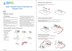
RSO 04 Microprocessor controller for solar systems User manual Warning Before the installation and use of this device read this manual. Violation of instructions written below can cause loss of warranty. Store this manual in a safe place. Made in EU 22.01.2009 1 Safety instructions This device must be disconnected from the power network before any intervention (mainly opening of the cover). Only qualified person can open, connect and put the device into operation who will also follow safety and other rules necessary for this job. Before any operation with device, it must be disconnected from the power network and it cannot be activated. Avoid touching the low voltage part (sensor, flowmeter) with the main power supply 230V. This can cause destruction of the device. Solar device can reach high temperatures that can cause burns, pay attention to the installation. Install the device in a place where the temperature cannot reach 50°C. The device is not protected from water (dropping, splashing, immersion) and that is why it must be installed in a dry place. If there’s any sign of defection, the system must be disconnected from operation. Check the materials used in the solar system to be appropriate in term of temperature endurance. If you have any questions in connection with you solar system, contact your distributor. 2 Shortcuts Attention! The symbol indicates possible danger. Attention: Voltage 230 V The symbol indicates danger of harming by electric current. Instruction/Procedure Pressing the button 3 Device description 3.1 Use RSO04 is a microprocessor, temperature differential regulator for control of solar thermal systems with one water exchanger and one solar collector array. The device is used for installation in a dry room in houses, shops and industry buildings. The device can be used for regulation of solar system as a solar regulator. In the case of other use, person providing the installation has to insure that all specifications and safety rules are compliant with this use. Use of the device for other purpose can cause loss of warranty. 3.2 Schemes Basic schemes of solar systems for RSO04 device are showed below. This scheme does not include complete hydraulic scheme. A Drain Back Systems: SCHEME 1 Pic. 1 SCHEME 2 Pic. 2 SCHEME 3 Pic. 3 SCHEME 4 Pic. 4 B Pressure systems: SCHEME 5 Pic. 5 SCHEME 6 Pic. 6 SCHEME 7 Pic. 7 SCHEME 8 Pic. 8 4 Summary of components Label Function 1 Sensors T1,T2, PC, Flowmeter 2 Conductive connection of sensor shielding 3 Outputs - pumps P1, P2 4 Power supply 5 Fuse 5 Installation of the device The device can be installed in dry rooms only, where’s no danger of explosion or fire. Open the device (qualified person only). You don’t need any tools to open the device. The upper cover is slipped-on on the lower in two leading gaps. Now you can connect cables. Before putting the device into operation, check the proper installation of the cover. You find that out by snapping the cover into leading gaps in both sides. Tight it with screws. 5.2 Installation on the wall During the installation on the wall, follow these steps: · Drill the holes with the help of applied sketch. · Open the cover and mount 4 screws. · To prevent the damage on the lower cover, mount the screws gently. Drilling to the wall is to your own risk. Before the drilling, check the power line under the plaster. In case of need, contact the householder. 6 Electrical connection See step 1 The device must be disconnected from the electric power supply and cannot be activated. All electric wires can be connected to the bottom side of the device. Connectors on the left side are designed for sensors and flowmeter. 230V power supply is on the right side. Terminal of the RSO04 are showed in the picture below. Ground T1 Temperature sensor – heat exchanger (for example lower part of the boiler) L Phase T2 Temperature sensor – solar collector N Neutral PUMP P1 Pump in the primary circuit - solar FL Flowmeter PUMP P2 PC PC Pump in the secondary circuit. (for example pool circuit, circulation pump of the hot water or cooling circuit) 6.1 230 V power supply Following instructions for connection of the power supply 230V must be kept: · The device must be disconnectable from the power supply in a mechanical way (removing of the fuse, unplugged from the wall, etc.) in the place of installation. · The device is designed for voltage. Pumps must be constructed for the same voltage. · All ground cables must be connected to the terminal tagged by 6.2 Connection of the temperature sensors The RSO04 device is equipped by platinum temperature sensors PT1000 (heat stability up to 280°C). Depending of the desired functions, 2 or 3 sensors are required. Installation / connection of thermal sensors: Install the sensors to assigned place in the collector array (output from the last collector in the array) and in the boiler, or other assigned place for the pool heating (boiler or straight in the pool). For the purpose of better heat transfer, you can use thermal paste. Sensors must be fixed in a place to touch walls. They can’t be free. Cables from the temperature sensors must be extended. For lengths up to 15m, it’s necessary to use cables 2 x 0.5 mm², for lengths up to 50m - 2 x 0.75 mm². We recommend to use shielded twisted pair. The shielding can’t overlap the sensor. We recommend to use also protection of the collector and devices against bolts. Connect the shielding to the ground of sensors – step 6 You don’t need to retain cable polarity of temperature sensors. Temperature sensors must be connected in terms of the terminal - step 6. Cables from sensors must be placed separately from the power supply cables - 230V. Before putting the device into operation, check the proper installation of the cover. You find that out by snapping the cover into leading gaps in both sides. Tight it with screws. 7 Operation The device RSO04 is controlled by 3 buttons: · Selection of values · Settings confirmation Graphical symbols on the display help to simplify operating structure and show actual values, parameters and currently chosen menu. 7.1 Explanation of graphical symbols Time Status Temperature Pump Energy gain 1:35 THXS 0 °C STOP S 2345.00 Graphical symbols Temperature Graphical symbol Status Description Boiler - temperature C Boiler – error Collector - temperature K Collector – error A Pump P1 – solar – primary circuit - ON S Pump P1 – solar – primary circuit – OFF B Pump P2 – pool – ON D Pump P2 – circulation pump of used warm water – ON T Temperature difference is sufficient to switch on the solar system W Temperature difference is not sufficient to switch on the solar system L Water temperature in the boiler is lower than the maximal adjusted temperature for the boiler H Water temperature in the boiler is same or higher than the maximal adjusted temperature for the boiler 1 Heat transmitting fluid is flooding the collector array 2 Stabilization of the temperature in the solar circuit 3 Pump P1 is working at full power 4 Pump P1 is regulating the operating speed X The collector is overheated V Cooling of the collector Adjusting Delta T for launching of the P1 pump Energy gain Display parameter setup Time setup F Device is OFF 7.2 MAIN MENU Menu SWITCH -ON – switch on OFF – switch off 1:35 THXS 0 °C STOP S 2345.00 2x Switch 5x 1x 1x Default settings: OFF Menu : Display settings – Temperatures on the display: 1:35 THXS 0 °C STOP S 2345.00 Boiler or collector Collector or boiler Default setting: collector 2x Main. Temp 1x Main. Temp Menu : Temperature difference for switching on of the pump P1: 2x 1x Diff. Temp 1x DT[ K] : or Values: ΔT[°K]: 0 - 50 Default setting: “7°K” Menu: Energy gain – general gain: 2x S4.57kWh 2x Energy gain – last 90 days: 5 ,2 1 kWh 1x 9 0 d ays Menu: Display settings: 2x 3x Display INVERSION: 1x Inv ersion: or ON or OFF CONTRAST: 1x or MENU: TIMES: 2x 4x Hours 1x or 10 : 10 or Pool – secondary pump P2 – timer delay It’s possible to use the regulator to regulate the pump P2 in the secondary circuit with the boiler. This output switches on the pump P2 together with the primary pump P1 for pool boiler and stops the pump P2 together with the pump P1, but with delay. or Values in seconds: 0-120 Default setting: 10 seconds OR Circuit pump of user warm water - secondary pump P2 – timer It’s possible to use the regulator for the secondary pump as a timer of the circuit pump or 7.3 SERVICE MENU Menu - open: Menu - exit Hold the button 5 seconds Hold the button 5 seconds After existing the menu, the device switches back to automatic mode SERVICE MENU MANUAL Torque w[%] Time t[s] TIMES Flux t[s] Stabil. t[s] TEMPERATURES Temp ON T[K] Temp PWM T[K] Temp OFF T[K] Maximal T.shock T[C] T[K] FLOWING Minimal Flow Comsump. Basin DHW Clear sum w[%] q[Lpm] P[W] t[s] t[s] CLR Explanation Manual control Testing – pump load P1 Testing – measure of times of pump P1 for flooding and stabilization Times setup Time for flooding the collector Time for stabilization of the collector Temperature setup Temperature difference for switching on of the solar circuit P1 Temperature difference for switching on of the regulation of the pump P1 regulation Temperature difference for switching off of the solar circuit P1 Maximal temperature for the boiler Max. temperature difference for switching on of the pump P1 Flow parameters Minimal pump P1 load Pump flow P1 - 100% Pump consumption Time for run down of pump P2 – pool Pump P2 timer – user warn water Clearing of the energy records Min Max Default 0 0 100 - 5 120 20 5 0 50 7 0 50 5 0 50 2 0 0 130 80 85 40 0 0 0 NO NO 100 20 250 YES YES 30 2 60 20 Drain Back System: This system has a collector circuit with flooding and draining of the cooling fluid – after fulfilling the activating condition (1. Insufficient temperature in the boiler, 2. Collector temperature higher of "Delta T" than the boiler temperature), the regulator switches on the pump for the time "Flux" in full power (when the fluid floods the collector), then lowers the pump load to minimal (“Minimal”, necessary to maintain the flow) for "Stabil" time – because of stabilization, then switches back to normal operation. After ending of the pumping, the cooling fluid is drained from the collector circuit. Note: For pressure system “Flux”= 0 seconds, “Stabil”= 0 seconds MANUAL: The device can be tested – measuring of “Minimal” (Minimal load of the pump P1 to maintain the flow) and measuring of times necessary for flooding the collector -“Flux and stabilization “Stabil”. TIMES: Setup of measured times for flooding of the collector -“Flux and stabilization “Stabil”. TEMPERATURES: Temperature difference – Delta T (°K): The device can regulate the pump load by pulse-width modulation of the output – to lower the load, the pump is switched off for tens of milliseconds. The load regulation is on, if in menu (see "Service Menu-Flowing-minimal") the value is lower than 100% during the time of stabilization (“Stabil”). The pump load is controlled after the decrease of the collector temperature difference under the level of the “switch on delta” - Temp PWM, then it’s lowered until the difference is under the “switch off delta”. 8 Collector overheating: If the boiler has enough energy and the solar radiation is strong, collectors may be overheated. Therefore, the regulator is equipped by a function to protect the overheating that can be activated in service menu. If the temperature is higher than 120 °C, pumping will be blocked until the temperature sinks below 120°C and until the temperature difference between the collector and the boiler sinks under the temperature difference “T.shock”. This works also during the power supply failure. FLOWING – Flow parameters: 9 Boiler overheating: If the temperature in the boiler is higher than adjusted value “Maximal”, the pump switches off. TO prevent the boiler overheating, it’s possible to use secondary pump P2 also to spend spare energy in the boiler. Values: T[°C]: 0 - 80 Note: The function Cooling “COO” is activated only if the pump P2 is activated - function “DHV” - YES . Cooling is programmed that the pump P2 will be active until the temperature of the boiler won’t be lower than the set temperature (default 25°C) under the maximal temperature ”Maximal”. After the cooling about set value in °C, the device switches to values for timing “Circulation pump of user warm water - secondary pump P2 – timer” if this timing is activated. 10 Technical data: Power supply voltage: Output voltage: Self consumption: Maximal output current: Cover: Operating temperature: Air pressure: Max. relative air humidity: Dimensions: Measured temperature range: Inputs: Precision: Outputs: Display: Control: Fuse: 230V/50Hz 230V/50Hz <1,5VA 4 A IP 40 0 up to 50°C 70 – 106 kPa 80% at 30°C 200 x 180 x 55 mm O - 250°C 2 to 3 temperature sensors type Pt1000 (heat stability 280°C), impulse flowmeter 1% 2 triac outputs 230VAC/max.4A graphical display 128 x 64 pixels 3 buttons 4 A, type T (slow reaction) Warranty: · Manufacturer provides warranty within 3 years from date of sale. · This warranty refers only to defects that were caused in standard use of supplied devices. This warranty does not refer to defects that were caused by unauthorized person, incorrect storage, unsuitable environment or vis majeure event (flood, fire, atmospheric discharge etc.). · User loses the warranty, if there was any intervention in the product. · Warranty and post-warranty service is ensured by the manufacturer.