1
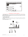
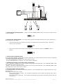
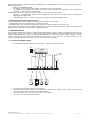
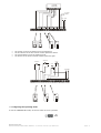
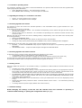
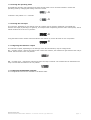
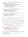
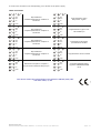
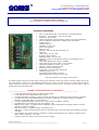
43-200 Pszczyna, ul. Staromiejska 31b
tel. 032 326 30 70, fax 032 447 73 30
www.gorke.com.pl, e-mail: [email protected]
SPECIFICATION AND USER’s MANUAL
type of the device: 4-channel receiver type RSW-004
TECHNICAL PARAMETERS
•
•
•
•
•
•
•
•
•
•
•
•
•
•
•
•
type of receiving module: superreaction or superheterodyne
sensitivity: -100 with SR (-115 with SH) dBm
frequency: 433,92 MHz
radio transmission: KeeLoq hopping code by Microchip Technology
memory capacity: 99 devices, including up to 20 sensors
voltage supply:
nominal: 12 V DC
allowable: 10-15 V DC
power consumption:
static: 40 mA
maximal: 100 with SR (120 with SH) mA
capacity:
relay output: 1A/ 30 V DC
S signal output: 500mA
sabotage output: 1A/ 30 V DC
number of relays: 6 (including 4 channel, 1 low battery level, 1
sabotage)
relay's operating mode: mono or bistable
time scope for the mono mode: ~0,2s-109min
operating temperature range: 0 to +40°C
antenna: outlet to clamp terminal
dimensions (mm): 99*62*29
cooperation: any GE sender and sensor
operating range (m)*:
superreactive SR module: 100-500
syperheterodyne SH module: 200-1000
* the range depends on the type of the sender
The above range concerns the open space (without any obstacles, when the receiver and the remote control can
“see each other”). If there are any obstacles between the receiver and the sender, one must assume that the
range would be reduced: for wood and plaster it would be 5-20% lower, for bricks 20-40% lower, and for
reinforced concrete 40-80% lower.
__________________ GENERAL CHARACTERISTICS OF THE DEVICE _______________
•
•
•
•
•
•
•
•
•
•
•
it can cooperate with the main wire alarm control panel
it can operate as an independent control panel
universal 4-channel controller – one can control any device, for example, a gate, a barrier or lighting
it cooperates with wireless GORKE Electronic sensors (CRB) and any remote controls by GORKE
Electonic (PUK, RNB, NRP) – up to 99 devices
S output (signals arm/disarm state); type: open collector (capacity: 500mA)
4 independent relay outputs for free use (capacity: 1A)
SAB/AL relay output – it signals sensors’ sabotage. In the independent operating mode it is used to
control the external signaller
BAT relay output – it signals sensors’ low battery level
UZB input – it arms the control panel with the external input – from the main control panel or external
encryptor
each channel may operate with five sensors or remote control buttons (the number is limited by the
total number of devices – up to 99)
memory of the arm state in case of lack of power supply
Gorke Electronic
SPECIFICATION AND USER’s MANUAL: 4-channel receiver type RSW-004
page: 1
GND ANT K1
JP1-4
JP7
JP6
JP5
JP6
JP5
NC
WE
K1
K2
K2
K3
K3
K4
K4 BAT BAT S
UZB
SAB/AL+12 GND
NO
PILOT
JP1
JP2
JP3
JP4
JP7
CENTR STER
UZB
K1
SAB
K2
BRAK
TESTU
K3
BAT
K4
ROZBR.
WYJŚCIE
PRG
WYBÓR
fig.1. – view of RSW-004
___________________ CHARACTERISTICS OF DEVICE’S OPERATING _________________
1. CONTOL PANEL mode - in this mode the RSW-004 controller with GORKE Electronic sensors (CRB), GORKE
Electronic remote controls (PUK, RNB, NRP) together with appropriately connected signaller enables the
protection of small objects. The control panel may be armed from an external encryptor or from a remote
control button ascribed to the channel 4.
2. Connection example scheme
- sensors on the channels 1 and 2
- arming from the button of the first remote control (or from an external encryptor, depending on the setting of
the J6 switch
- the arming is signalled while arming from the remote control – the diode is connected to the output of the
channel 4 (channel 4 in the bistable mode)
- work with external signaller
szyfrator
sygnalizator
Buzzer
12V
+
GND ANT K1
K1
K2
K2
K3
K3
K4
K4
BAT BAT
S
Gorke Electronic
SPECIFICATION AND USER’s MANUAL: 4-channel receiver type RSW-004
UZB
+12V GND
SAB/AL + 12 GND
page: 2
szyfrator
Buzzer
12V
+
Nadajnik
lub
dialer
SAB/ALARM
BATERIA
UZB./ROZBR.
NAPAD
K2/ALARM
K1/ALARM
K2
K2
K3
K3
K4
K4
zbr.
r./ro
uzb
K1
d
pa
na
GND ANT K1
+12V GND
BAT BAT
S
UZB
SAB/AL + 12 GND
3. Configuring the operating mode - in order to set the CONTROL PANEL mode, you need to set the J5 switch
in the 1-2 position.
1
2
3
J5
4. Choosing the arming method - The control panel may be armed and disarmed in two ways, depending on
the setting of the JP-6 switch:
•
with the arming input (by shorting to ground), for example from an external encryptor. Set the J6
switch in the 1-2 position:
1
•
2
3
J6
with the the button of the remote control assigned to the channel 4. Set the J6 swtich in the 2-3
position
1
2
3
J6
5. Control panel’s operating states
The control panel operates in two states: armed or disarmed. The present state and all the events are signalled
by lighting the appropriate LED diodes.
- the green ARMED diode is lighted – the control panel is armed
- the blue DISARMED diode is blinking – the control panel is disarmed
6. Signalling the change of arm state of the control panel
- arm – this state is signalled by a single impulse on the S output and optionally in the CONTROL PANEL mode
the ALARM relay will be open for 300ms
- disarm – this state is signalled by two impulses on the S output and optionally in the CONTROL PANEL mode
the ALARM relay will be open twice for 300ms
7. Receiving signals from the sensors
The channel to which the sensors are ascribed operates in the monostable mode (it gets activated for a predefined period).
If an alarm is received from a sensor:
and the control panel is armed – the red diode corresponding to the channel will light and the relay in
the channel will open
and control panel is disarmed – the red diode corresponding to the channel will blink and the relay will
not be open
Gorke Electronic
SPECIFICATION AND USER’s MANUAL: 4-channel receiver type RSW-004
page: 3
Opening the case of the sensor will cause a sabotage alarm, independently of the arm state of the control panel.
It will be signalled by:
lighting the SABOTAGE diode
an impulse on the output of the channel to which the sensor was ascribed
an impulse on the ALARM relay output (one minute interval between the impulses); if the control panel
is armed – up to five times on the arming
Independently of the arm state, the control panel receives signals from the sensors:
NO TEST – it generates an impulse on the ALARM relay output or on the S output and it is signalled by
lighting the NO TEST diode
LOW BATTERY LEVEL – it opens the BAT relay output and lights the BATTERY diode
8. Receiving signals from remote controls
A channel to which a remote control was ascribed may operate in two modes:
- a monostable mode (it is activated for a pre-defined period)
- a bistable mode (each stimulation changes the state of the channel output on the other one)
In both cases the channel gets activated, independently of the arm state of the control panel. The blinking red
diode which corresponds with the channel signals the activity.
9. CONTROLLER mode
In this mode the RSW-004 controller together with GORKE Electonic sensors (CRB) may extend the existing wire
alarm system, if the control panel is appropriately connected. Together with the GORKE Electronic remote
controls (PUK, RNB, NRP) it allows for arming and disarming the existing wire alarm system using the remote
control. The RSW-004 controller which operates in this mode may be used as a universal controller of, for
example, lighting and gates, activated either by remote controls or sensors.
10. Connection example scheme
•
the controller cooperates with the control panel – sensors on all four channels
szyfrator
Centrala
alarmowa
WE WE WE WE WE
TAMPER
do obwodu
sabotażu
+12V GND
GND ANT K1
•
•
•
•
K1
K2
K2
K3
K3
K4
K4
BAT BAT
S
UZB
SAB/AL + 12 GND
the controller cooperates with the control panel
arming the alarm control panel with the first button of the first or second remote control on the channel
4 (this channel needs to be set on the bistable mode)
the second button of the first remote control – panic button
sensors on the first and second channel
Gorke Electronic
SPECIFICATION AND USER’s MANUAL: 4-channel receiver type RSW-004
page: 4
Centrala
alarmowa
TAMPER
UZBR./ROZBR.
NAPAD
BATERIA
K1
K2
WE WE WE WE WE
do obwodu
sabotażu
+12V GND
GND ANT K1
K1
K2
K2
K3
K3
K4
K4
BAT BAT
ozbr.
r.
zb
uzbr./r
the
the
the
the
SAB/AL + 12 GND
UZB
o
./r
br
uz
•
•
•
•
S
sensor on the first channel turns the lighting on
first button of the first remote control opens the wicket
second button turns the lighting on/off
button of the second remote control opens the gate
oświetlenie
brama
M
oświetlenie
+
24V
-
+ 24V
-
furtka
+
24V
-
+12V GND
K1
K2
K3
K3
K4
K4
BAT BAT
S
UZB
SAB/AL + 12 GND
ma
bra
furtka
oświetle
K2
nie
ietle
ośw
nie
GND ANT K1
11. Configuring the operating mode
To set the CONTROLLER mode, set the J5 switch in the 2-3 position.
1
2
3
J5
Gorke Electronic
SPECIFICATION AND USER’s MANUAL: 4-channel receiver type RSW-004
page: 5
12. Controller's operating states
The controller operates in two states: armed and disarmed. The present state and all events are signalled with
lighting appropriate LED diodes.
•
green ARM diode is lighting – the control panel is armed
•
blue DISARM diode is blinking – the control panel is disarmed
13. Signalling the change of a controller's arm state
•
•
armed – a single impulse on the S output
disarmed – two impulses on the S output
14. Receiving signals from sensors
The channel to which the sensors are ascribed operates in the monostable mode (it gets activated for a predefined period).
If an alarm from a sensor is received:
•
and the control panel is armed – the red diode corresponding to the channel will light and the relay in
the channel will open
•
and the control panel is disarmed – the red diode corresponding to the channel will blink and the relay
will not be open
Opening the case of the sensor will cause a sabotage alarm, independently of the arm state of the control panel.
It will be signalled by:
•
lighting the SABOTAGE diode
•
an impulse on the output of the channel to which the sensor was ascribed
•
closing the relay output (disconnecting the TAMPER circuit) until the sabotage alarm disappears
Independently of the arm state, the control panel receives signals from the sensors:
•
NO TEST – it closes the SABOTAGE relay output or opens the S output. It is signalled by lighting the NO
TEST diode
•
LOW BATTERY LEVEL – it opens the BAT outputs and lights the BATTERY diode
15. Receiving signals from remote controls
A channel to which a remote control was ascribed may operate on two modes:
•
a monostable mode (it is activated for a pre-defined period)
•
a bistable mode (each stimulation changes the state of the channel output on the other one)
In both cases the channel gets activated, independently of the arm state of the control panel.
The blinking red diode which corresponds with the channel signals the activity.
16. Reading events
When the RSW-004 controller is in the disarm state, it is possible to read the alarms received earlier from the
sensors.
•
to display the events, press the PRG button
•
if the controller receives any alarm, it will be signalled with blinking diode on the appropriate channel.
The number of blinks indicates the number of device on this channel, for example, a double blink of the
red K3 diode means that the alarm came from the second device on the third channel.
•
the SABOTAGE, LOW BATTERY LEVEL and NO TEST alarms are be displayed in analogical way but except
lighting the red diode to signal channel and device, the yellow diode (SABOTAGE, LOW BATTERY LEVEL
or NO TEST) will be lighted too.
•
pressing the PRG button once more deletes the event just read and the next event is displayed (if there
is any)
•
keeping the PRG button pressed for about 4 seconds deletes all the events – it is confirmed by blinking
yellow diodes.
•
re-arming and loss of power supply deletes the events memory.
17. Switches settings
NOTE! Changing the settings of the JP5 and JP6 switches when the controller is operating is
confirmed while entering or quitting the configuration menu (cf. p.7).
Gorke Electronic
SPECIFICATION AND USER’s MANUAL: 4-channel receiver type RSW-004
page: 6
18. Choosing the operating mode
The RSW-004 controller may operate as an alarm control panel or as a universal controller. Choose the
operating mode by changing the setting of the JP-5 switch.
1
2
3
1
2
3
J5
J5 switch in the position 1-2 - controller
J5
19. Choosing the arm input
The controller, depending on the setting of the JP-6 switch may be armed or disarmed in a twofold way:
with the arm input (by shorting it to ground), for example when cooperating with the main control panel; the J6
switch needs to be set in the 1-2 position:
2
1
3
J6
using the button of the remote control ascribed to the channel 4; set the J6 switch on the 2-3 position
1
2
3
J6
20. Configuring the channels' outputs
The channels' outputs, depending on the settings of the JP1-JP4 switches, may be configured as:
NC – normally closed – opening the channel will unshort the contacts; the contacts will get shorted if the relay is
closed. Set the switch in the 2-3 position.
1
2
3
NO – normally open – opening the channel will short the relay's contacts. The contacts will be unshorted if the
relay is closed. Set the switch in the 1-2 position.
1
2
3
21. Configuring the RSW-004 controller
The configuration functions are available in the disarm state.
Gorke Electronic
SPECIFICATION AND USER’s MANUAL: 4-channel receiver type RSW-004
page: 7
___________________________ PROGRAMMING ___________________________
1. Entering the senders into the controller's memory
The controllers has four independent channels to which one can ascribe the remote controls' buttons or sensors,
keeping in mind that if you enter a sensor as the first device, then you will be able to enter only sensors in this
channel (up to 5 in one channel). If you enter a remote control's button as the first – then only remote controls
can be entered (no limits on the channel; it is limited only with the maximal number of devices – up to 99).
If the controller is configured to be armed from a remote control, the fourth channel will be used for the remote
controls arming and disarming the controller. Entering a sensor to this channel will disable the option of arming
the controller.
Moreover, if sensors were entered on the fourth channel and the way of arming was changed from arming with
the arm input to arming with the remote control, one will need to delete the devices entered on the channel four
and programme there a remote control button.
One must remember that every remote control button is treated as a separate device.
2. Entering a device
1)
press the CHOICE button, the red K1 diode will light (which corresponds to the channel one), with next
pressing – the diode K2 will light, etc.
2) press the PRG button – the red diode will start to blink
3) depending on the device:
- a remote control – press the remote control button twice – the proper learning will be confirmed by a
signal on the S output and a blink of the DISARM diode
- a sensor – take the sensor's case off, then press the sensor sabotage button and keep it pressed until
the proper learning is confirmed by a signal on the S output and a blink of the DISARM diode.
4) quit the menu by pressing the QUIT button.
NOTE! In case the devices memory is full, trying to programme the 100th device will be signalled by five blinks of
the red diodes and the programming mode will be quitted.
3. Deleting devices on a channel
1)
2)
3)
press the SELECT button. The red K1 diode will light (which corresponds to the channel one), next
pressing will light the K2 diode, etc.
keep the PRG button pressed for about 4 seconds – deletion of the devices on the channel will be
confirmed by a quick blinking of the red diode.
quit the menu by keeping the QUIT button pressed.
4. Deleting all devices
1)
2)
3)
press the SELECT button until all four red diodes light
keep the PRG button pressed for about 4 seconds – deletion of all devices will be confirmed by a quick
blinking of the red diodes.
quit t he menu by keeping the QUIT button pressed.
5. Restoring the default settings
Default
•
•
•
•
•
•
1)
2)
3)
settings:
outputs of all channels in the monostable mode
period of output activity: 2s
sensors' test period – 260 min
empty devices memory
signalling the arm state with the ALARM relay – disabled
signalling NO TEST with the S output
press the SELECT button until all four red diodes light
keep the PRN button pressed for about 8 seconds – restoring the default settings will be confirmed by
blinking red diodes and then the red diodes will light and fade.
to quit the menu, press the QUIT button
6. Programming the activity period of the output
1)
2)
3)
4)
5)
6)
press the SELECT button until the yellow SABOTAGE diode lights
press the PRG button – the first red diode will light
using the SELECT button, choose a channel – it will be indicated by an appropriate red diode
press the PRG button and keep it pressed as long as the given output is supposed to be active. The
minimal period is 0,2 second, and the maximal period is 90 mins.
release the PRG button – all the previously lighted diodes will blink
quit the menu by keeping the QUIT button pressed
Gorke Electronic
SPECIFICATION AND USER’s MANUAL: 4-channel receiver type RSW-004
page: 8
7. Programming the monostable or bistable outputs
The bistable mode on the channel's output can be programmed only on the channel in which remote controls
were programmed.
1) press the SELECT button until the yellow NO TEST diode lights
2) press the PRG button – the first red diode will light
3) using the SELECT button, choose a channel – it will be indicated by the appropriate red diode
4) press the PRG button to change the output's mode. It will be confirmed by:
- a single blink of the red diode – the monostable mode
- a double blink of the red diode – the bistable mode
(if the output is in the monostable mode before making changes in the state, after the operation it will
flip into the bistable mode and the other way round.)
5) quit the menu by pressing the QUIT button
8. Signalling the arm state with the ALARM relay
The function turns on/off the signalling of the arm/disarm state of the RSW-004 in the CONTROL PANEL mode
with the ALARM relay.
1) press the SELECT button until the yellow BATTERY diode lights
2) press the PRG button and change the function settings. It will be confirmed by:
- a single blink of the BATTERY diode – signalling is turned on
- a double blink of the BATTERY diode – signalling is turned off
3) quit the menu by pressing the QUIT button
9. Programming the test period
The test period is time in which the test signal is supposed to be received. If during the programmed period the
signal is not received, the NO TEST alarm will be signalled.
1) press the SELECT button until the DISARM diode lights
2) press the PRG button – the first red diode will light
3) using the SELECT button, choose a channel – it is indicated with the red diode in accordance with the
following table (X indicates a lighting diode):
Period [min]
Diode
Yellow
SABOTAGE
Yellow
NO TEST
X
Yellow
BATTERY
X
15
X
X
30
X
X
60
X
65
X
X
130
X
X
260
X
X
X
4)
5)
X
Blue
DISARM
Press the PRG button to programme a chosen period – it is confirmed with blinking red diodes
quit the menu by pressing the QUIT button
10. Signalling NO TEST with the SABOTAGE/ALARM or S output
This function allows for defining whether the NO TEST is supposed to be signalled with the S output or with the
SABORAGE/ALARM relay output.
1) press the SELECT button until the green ARM diode lights
2) press the PRG button to change function setting – it is confirmed by:
- a single blink of the ARM diode – signalling with the SABOTAGE/ALARM output
- a double blink of the ARM diode – signalling with the S output
3) to quit the menu, press the QUIT button
11. Measuring the signal strength
The RSW-004 controller allows for measuring the power of the senders' signal. It is represented by lighting the
diodes: the power of the signal is proportional to the number of lighting diodes. In order to enter the function of
measuring the power:
•
turn the power supply off
•
take the case off and press simultaneously the PRG and SELECT buttons
•
turn the power supply off
Gorke Electronic
SPECIFICATION AND USER’s MANUAL: 4-channel receiver type RSW-004
page: 9
To restore the controller's normal operating, turn off and on the power supply.
Table of functions
UZB
K1
SAB
K2
BRAK
TESTU
K3
BAT
K4
ROZBR.
K1
SAB
K2
BRAK
TESTU
K3
BAT
K4
ROZBR.
K1
SAB
K2
BRAK
TESTU
K3
BAT
K4
ROZBR.
K1
SAB
K2
BRAK
TESTU
K3
BAT
K4
ROZBR.
K1
SAB
K2
BRAK
TESTU
K3
BAT
K4
ROZBR.
Wprowadzanie
urządzenia/kasowanie urządzeń w
kanale K1
UZB
Wprowadzanie
urządzenia/kasowanie urządzeń w
kanale K2
UZB
Wprowadzanie
urządzenia/kasowanie urządzeń w
kanale K3
UZB
Wprowadzanie
urządzenia/kasowanie urządzeń w
kanale K4
UZB
Kasowanie wszystkich urządzeń /
przywrócenie ustawień fabrycznych
K1
SAB
K2
BRAK
TESTU
K3
BAT
K4
ROZBR.
K1
SAB
K2
BRAK
TESTU
K3
BAT
K4
ROZBR.
K1
SAB
K2
BRAK
TESTU
K3
BAT
K4
ROZBR.
K1
SAB
K2
BRAK
TESTU
K3
BAT
K4
ROZBR.
K1
SAB
K2
BRAK
TESTU
K3
BAT
K4
ROZBR.
UZB
Programowanie czasu
aktywności wyjścia
UZB
Programowanie wyjść monolub bistabilnych
UZB
Sygnalizacja uzbrojenia
przekaźnikiem ALARM
UZB
Programowanie okresu testów
UZB
Sygnalizacja BRAK TESTU
wyjściem SABOTAŻ/ALARM
lub S
The device meets the requirements of the directive EMC 89/ 336/ EEC
and RTTE 1999/ 5/ EC.
Gorke Electronic
SPECIFICATION AND USER’s MANUAL: 4-channel receiver type RSW-004
page: 10