1
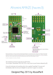
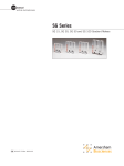
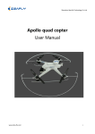
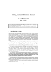
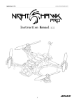
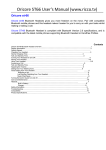
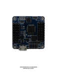
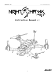
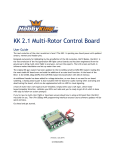
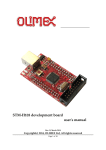
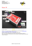
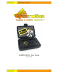
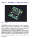
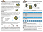
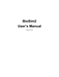
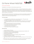
Flight Controller
「なぜ」
「Naze32」
Mini Fun Fly
Create by AbuseMarK 2012
Mini FunFly Flight Controller “Naze32” (なぜ)
Introduction
Mini Flight Controller「なぜ」(pronounced「Naze」)
36x36mm.
6 grams (no headers, 8 grams with).
Modern 32-bit ARM processor running at 3.3V/72MHz.
MEMS gyro, accelerometer, compass and pressure sensor.
Acrobatic, auto-level, heading hold, head-free, altitude hold flight mode.
Support Quad-, Tri-, Hex-, Octo-, various coaxial configurations, as well
as fully customizable motor mixer for any airframe type.
Flexible RC input - Standard, CPPM, Spektrum satellite.
Battery voltage monitoring and low voltage alarm.
FrSky telemetry transmission support.
Onboard USB for setup and configuration.
MultiWii-based configuration GUI.
Flying wing, airplane mixer. (1)
GPS position hold / return to home. (1)
Designed for use with small indoor or small to mid-sized outdoor
multirotor craft, or as a standalone camera stabilizer, the Naze32
flight control is simple to setup, with configuration based on
the familiar “MultiWii” software.
(1)
Work in progress
WARNING Using this hardware with any DJI frames is not supported.
This includes: FlameWheel 330, 450, 550, or any future or past frames released by DJI.
WARNING Do not use this hardware for serious business, commercial aerial photography,
or anything else where its usage could endanger the end user, spectators, inanimate
objects, aircraft flying overhead, etc.
NOTE While the flight controller firmware and configuration software is based on the
MultiWii system, the processor is not Atmel AVR, and this hardware cannot be programmed
through the Arduino development environment or any AVR development tools. For more
information on STM32 development, see the following link:
http://code.google.com/p/afrodevices/wiki/STM32Development
NOTE This hardware is provided as-is and end-user is expected to have reasonable
technical knowledge to complete set-up and reasonable R/C experience to operate
multi-rotor aircraft.
Mini FunFly Flight Controller “Naze32” (なぜ)
Hardware and Connection (Top)
1
6 ESC/Servo
Headers
“Front” direction
3 Buzzer connector
2
8
RC
Input
(CPPM/PWM)
Motor output
Status LEDs
(Red, Green)
Fig. 1 Top View
M3 mounting hole
30.5mm spacing
Power LED
(Blue)
USB Port
4
Battery Connector
for Voltage Monitor
Board is 36x36mm square, with mounting holes for M3 screws, spaced 30.5mm.
[1] ESC / Servo Headers
[2] RC Input / Servo Output (CPPM / PWM) / GPS connector
Described in detail in “Motor and Receiver connections” chapter.
[3] Buzzer
5V Buzzer, connect a header here, + and - are marked and should be followed.
[4] Optional Battery Voltage Monitor
To enable in-flight battery voltage monitoring and alarm, connect this header to
flight battery or power distro board. Up to 25V (6S LiPo) can be measured. No reverse
polarity protection - connecting battery in reverse will instantly destroy the hardware.
[8] Telemetry / Bluetooth / XBee serial port
RX and TX connectors from the USB Serial converter are available here. Can be used
to connect Bluetooth / XBee / etc to allow changing settings without connecting USB.
Cannot be used at same time with USB connection.
Mini FunFly Flight Controller “Naze32” (なぜ)
Hardware and Connection (Bottom)
5
7
6
Fig. 2 Bottom View
[5] Bootloader pads
In case automatic firmware update fails or for upgrading from older firmware.
Use a paperclip or tweezers to short pads together and connect power to the board.
Firmware update tool can then be used to reload firmware.
[6] Cortex Debug Connector
10 pin 0.05” debug connector connected to ‘SWD’ port of STM32.
Pin 1 is bottom left.
[7] I2C Connector
SDA and SCL from the sensor I2C bus are connected here. Can be used for additional
sensors or debugging.
GND
5V
Signal
Mini FunFly Flight Controller “Naze32” (なぜ)
Motor and Receiver Connections
1 2 3
S1
M1
S2
M2
Signal
M1
M3
M2
M4
M3
M5
4 5 6 7 8
M5 M6 M7 M8
NOTE: When using CPPM receiver only!
M4
M6
Servo
Mode
Standard
Mode
Fig. 3 Motor connections
Depending on selected motor configuration and receiver type, up to 8 motors or servos
can be connected. Headers on top of the board 1 can be used for 6 motors or 2 servos
and 4 motors. The pins towards center of the board are signal pins. Following that is 5V,
and then Ground/GND pins.
WARNING Incorrect or reverse connection to these pins will instantly destroy the
hardware.
When CPPM receiver is used, RC input connector can be used for additional motor and
servo outputs. Refer to the diagram in Fig. 3 Motor connections.
Some CLI configuration options affect motor and servo numbering, see the
“Serial Console” chapter for more details.
G ● 1 2 3
Fig. 4 Receiver connections
4 5 6 7 8
With the connector facing out, the pins are used as follows. Unmarked pin
(left-most top side) is ground, pin marked with dot is 5V supply, the rest are
RC signal pins for CPPM (channel 1) or channels 1 through 8.
Standard female to female servo cable can be used to connect a CPPM receiver.
Default channel order is AIL, ELE, THR, RUD, AUX1..AUX4. A breakout cable is provided
for connection to standard receiver.
When GPS feature is enabled, channels 3 and 4 are are used for 3.3V GPS connection.
(3:TX, 4:RX). with CPPM receiver, these are normally unused, with standard receiver,
connect AIL to 1, ELE to 2, THR to 5, RUD to 6, and AUX1/2 to channels 7 and 8.
With CPPM receiver, channels 5 to 8 can also be used as motor or servo outputs,
depending on airframe type and configuration.
Mini FunFly Flight Controller “Naze32” (なぜ)
Motor Mixer Settings
Images below show motor numbering and propeller rotation for various supported mixes.
The number corresponds to the motor index (M1 to M8) from Fig 3. Motor connections.
NOTE Configurations with more than 6 motors require CPPM receiver.
In all cases, the “front” arrow on flight control board should point in same direction as
red arrow in these illustrations. For Y4 and Y6 mixes, purple motors are top, and blue is
bottom. In servo mode (Tri-/Bi-/Camera Stabilization), motor numbers change according to
the diagrams below. When using CPPM receiver additional 4 motor outputs are available
for Hexa- with gimbal, or Octo- configuration.
NOTE In Tri-copter mode, tail tilt servo connects to S1, and motors M1..M3 as shown in
Fig 3. Motor connections on the previous page. When camera stabilization is enabled,
gimbal pitch/roll servos connect to S1/S2, and motor connectors shift as well.
It’s also possible to program a completely custom mix for up to 10 motors. For more
details, see the “Serial Console” chapter.
4
4
3
2
3
3
1
1
1
S1
3
Y4
TriCopter
QuadCopter-Plus
6
5
2
4
4
2
3
1
3
2
5
6
1
3
6
Hexa-X
5
1
6
8
3
4
7
Octo-X
?
Hexa-Plus
2
2
2
1
QuadCopter-X
(default)
4
2
Custom Mix
1
4
Y6
5
Mini FunFly Flight Controller “Naze32” (なぜ)
Camera Stabilization and Gimbal Mode
Naze32 can be used as a standalone camera gimbal stabilization unit. By setting multirotor
type to “Standalone Gimbal Stabilization”, servo outputs 1 and 2 can drive camera gimbal
servos. Both analog (50Hz refresh) and digital (200Hz+ refresh) servos are supported.
Servo gain (amount of servo travel for given angle of tilt) is configurable for both pitch
and roll axis.
In addition to standalone stabilization, camera outputs can also be enabled when used as
a standard multirotor controller. In case of standard receiver, this limits to Quad mixer.
In case of CPPM receiver, up to Octo can be supported while still allowing for camera control.
Channels AUX3/AUX4 can be assigned to tilt/roll the camera mount in addition to
stabilization. See “Serial Console” chapter for more details.
Servo 1
Pitch Axis
Servo 2
Roll Axis
GND
5V
Signal
NOTE Make sure the aircraft is level when powering up in standalone gimbal stabilization
mode.
S1
S2
M1
M2
M3
M4
Servo
Mode
Fig. 5 Gimbal servo connections
WARNING If using high-current-draw servos for camera stabilization, consider powering
them from a separate BEC. Only connect Signal and GND wire to the board, and 5V wire
from servos to a separate power source.
Mini FunFly Flight Controller “Naze32” (なぜ)
Firmware Upgrade part 1 (bootloader)
Hardware is shipped with the most current firmware at the time of assembly. It is
recommended to upgrade to latest stable or development firmware for new features.
Update requires the following tools:
1. Flash Loader Demonstrator http://code.google.com/p/afrodevices/downloads/list
2. Hercules SETUP utility http://www.hw-group.com/products/hercules/index_en.html
3. Latest baseflight firmware (development)
http://code.google.com/p/afrodevices/source/browse/trunk/baseflight/obj/baseflight.hex
NOTE Hardware should be connected only by USB. Do not perform firmware update while
flight battery is connected.
Entering bootloader mode
Method 1
1. Run Hercules SETUP and switch to “Serial” tab.
2. Choose COM port, baudrate of 115200, 8bit, no parity.
3. Click Open button.
4. In any 3 of the Send boxes, write in “R”.
5. Click the Send button.
All 3 LEDs will be ON, indicating the hardware is in
bootloader mode.
6. Proceed to ‘Firmware Update’ steps on next page.
Method 2
NOTE This is the rescue/recovery method. Under normal
circumstances it should not be necessary.
1. Temporarily short the bootloader pads using tweezers
or a paper clip. Do NOT solder them together.
2. While bootloader pads are still shorted, apply power.
Only the POWER (blue) LED will be ON at this point.
If any of the status LEDs blink, repeat from beginning.
3. After confirming that only POWER LED is ON, bootloader
pads can now be unshorted.
4. Proceed to ‘Firmware Update’ steps on next page.
Fig. 6 Hercules SETUP
Mini FunFly Flight Controller “Naze32” (なぜ)
Firmware Upgrade part 2 (actual update)
Once hardware is in bootloader mode (see previous page), Flash Loader Demonstrator
can be used to flash the firmware.
Firmware update
1. Run Flash Loader Demonstrator
2. Choose COM port, baudrate of 115200, make sure parity is set to EVEN.
3. Click “Next” button several times. When asked to choose device size, if 128K is not
selected, choose it.
4. On the last page (see Fig 7 Flash Loader), choose:
- Download to device.
- Browse to the location of .hex file to update.
- Choose “Erase necessary pages” to keep settings (firmware may still clear them) or
“Global Erase” to erase all settings and return to defaults.
- Check “Jump to user program” checkbox.
- Uncheck “Verify after download” checkbox.
5. Click the “Next” button.
After successful update, the board will reboot, flashing status LEDs in the usual pattern.
Fig. 7 Flash Loader Demonstrator
Mini FunFly Flight Controller “Naze32” (なぜ)
Command Line Interface / configuration
Command Line Interface (hereafter CLI) is used to configure most functions of the board.
A terminal program (such as PuTTY or HyperTerminal) should be used.
Download PuTTY from http://www.chiark.greenend.org.uk/~sgtatham/putty/
Connect to USB Serial port at 115200 baud,
8bit, no parity, 1 stop bit. These are default
settings for most terminal programs. To enter
CLI, type ‘#’ into the terminal.
A message will be printed,
Entering CLI Mode, type 'exit' to return, or 'help'
Fig. 8 PuTTY Configuration
Command line is interactive, and most commands will print something in return.
Available commands:
help
defaults
feature
map
cmix
mixer
set
status
version
save/exit
print out a list of all commands with short description of each
reset all settings to built in defaults, and reboot
enable, disable, or list enabled features (such as CPPM input, GPS, etc)
configure RC channel mapping for CPPM and standard receiver
create custom motor mix for non-standard airframe type
set or show current multirotor mixer (such as Quad-/Hexa-/etc)
set or list available parameters. Many settings are available.
print out system status (voltage, uptime, enabled sensors, etc)
print out firmware version and build date/time
save settings and reboot
WARNING Any changes to settings in cli, in particular related to motor output (throttle
values, etc) are accepted REALTIME and may result in motors starting up without warning.
Always configure with props disconnected or when model is only powered by USB.
Common usage examples:
To enable CPPM receiver, enable PPM feature:
# feature ppm
# save
To disable battery voltage monitoring, disable VBAT feature:
# feature -vbat
# save
To enable camera stabilization and change mixer to Quad-Plus:
# mixer quadp
# feature servo_tilt
# save
To configure CPPM receiver for EATR channel order and swap AUX1/2:
# map EATR2134
#save
Settings are applied real-time, however not saved until ‘save’ or ‘exit’ command is executed.
Mini FunFly Flight Controller “Naze32” (なぜ)
Frequently forgotten things
Few things need to be done to ensure smooth flying
experience. The guidelines below should cover most common
setup issues.
Do not move the model while plugging in the battery and during
the first few seconds after power-up. Gyro must be idle, or else
initial calibration will be wrong. Alternatively, make sure to
execute the “Gyro Calibration” stick sequence prior to arming.
NG OK
Fig. 9 Trim
First flight should always be in gyro-only mode. Do not enable auto-level, baro, headfree, etc
until you know what you’re doing.
If model immediately flips on take off, double-check board orientation (front facing), each
motor number, rotation direction, and type of prop installed. Refer to “Motor Mixer” chapter
for details.
Trim transmitter once, and never trim in-flight. Connect to GUI,
and subtrim on transmitter until all channels are centered at 1500.
If using Futaba gear, center might be 1520. In that case, set midrc value in config to
1520, then subtrim to center all channels at 1520. Do not use trim in flight for either gyro
or auto-level mode. Use acc-trim function.
Cover the barometer with open-cell foam and keep it away from direct sunlight. Placing the
flight controller in a plastic enclosure of some kind is recommended.
Mini FunFly Flight Controller “Naze32” (なぜ)
Stick Actions
Motor Arm
Motor Disarm
Gyro calibration
Acc calibration
Mag calibration
Acc trim