1
Warning
E
N
G
L
I
S
H
This document relates to use of the Altivar 58
exclusively with :
- the VW3A58101 display module
- a VW3A58201 or VW3A58202 I/O extension
card if applicable.
Some modes, menus and types of operation can
be modified if the speed controller is equipped
with other options. Please refer to the relevant
documentation for each of these options.
Since it was first commercialised, the Altivar 58
has had additional functions included. This
document can be used with earlier devices, but
parameters described here may be missing from
those speed controllers.
For installation, connection, setup and
maintenance instructions, please refer to the Altivar
58 and the I/O extension card User's Manuals as
required.
56
ATV 58 EN
56
22/05/01, 9:23
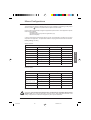
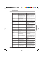
Contents
Introduction
58
Practical Advice / Minimum Setup
61
Unlocking Menus Before Programming
62
Access to Menus
63
Access to Menus - Programming Principle
64
Macro-Configurations
65
Drive Identification
67
Display Menu
68
Adjust Menu
69
Drive Menu
74
Control Menu
78
I/O Menu
81
Configurable I/O Application Functions
85
Fault Menu
96
Files Menu
98
Communication and Application Menus / Assistance During Operation / Maintenance
100
Saving the Configuration and Settings
104
Summary of Menus
106
Index
108
57
ATV 58 EN
57
22/05/01, 9:23
E
N
G
L
I
S
H
Introduction
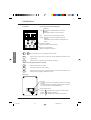
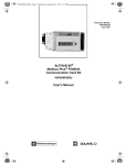
The VW3A58101 display module is supplied with ATV58iiiiM2 and ATV58iiiiN4 speed
controllers.
ATV58iiiiiiZ speed controllers are supplied without a display module. This can be ordered
separately.
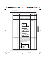
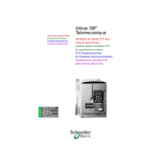
Installing the display module on the speed controller :
The protective cover should be removed before installing the display module on an ATV58iiiiiiZ
speed controller.
POWE
R
FAUL z
T
POWE
R
FAUL z
T
E
N
G
L
I
S
H
ESC
FWD
REV
ENT
RUN
STOP
RESE
T
The display module must be connected and disconnected with the power off. If the display module
is disconnected when control of the speed controller via the display module is enabled, the speed
controller locks in fault mode SLF
SLF.
Installing the display module remotely :
Use the kit, reference VW3A58103, comprising 1 cable with connectors, the parts required for
mounting on an enclosure door and the installation guide.
Signaling on the front panel of the Altivar
}
Other LEDs, indicating status with communication option cards
POWER z
Green LED POWER
FAULT
Red LED
FAULT
z
on : Altivar powered up
• on : Altivar faulty
• flashing : Altivar locked once the "STOP" key
has been pressed on the display module or
after a change to the configuration. The
motor can then only be supplied with power
after resetting prior to the "forward", "reverse",
and "injection stop" commands.
58
ATV 58 EN
58
22/05/01, 9:23
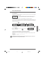
Introduction
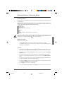
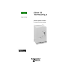
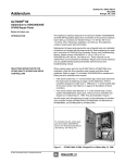
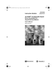
☞ Before switching the Altivar on and before using the display module :
Unlock and open the cover of the Altivar to
access the 50/60 Hz selector switch 1 on
the control card. If an option card is present,
the selector switch can be accessed
through it.
Position the selector switch on 50 or 60 Hz,
whichever corresponds to your motor.
Preset operating point :
1
50 Hz position (factory setting) :
- 230 V 50 Hz for ATV-58iiiiM2
- 400 V 50 Hz for ATV-58iiiiN4
60 Hz position :
- 230 V 60 Hz for ATV-58iiiiM2
- 460 V 60 Hz for ATV-58iiiiN4
or
50 Hz
60 Hz
E
N
G
L
I
S
H
The display module is used for :
-
Displaying the drive identification, electrical values, operating or fault parameters
Altering the Altivar settings and configuration
Operating in local control mode via the keypad
Saving and restoring the configuration in a non-volatile memory in the display module
59
ATV 58 EN
59
22/05/01, 9:23
Introduction
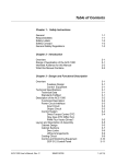
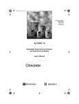
Front panel
Use of keys and meaning of displays
LOC
LOC
Indicates control via the display module
PROG Appears in setup and programming mode
Flashing :
indicates that a value has been modified but not
saved
ENT
RUN
Flashing :
indicates the selected direction of rotation
Steady :
indicates the direction of motor rotation
PROG
ESC
FWD
REV
 Ú
STOP
RESET
4-character display :
displays numeric values and codes
One line of 16 characters :
displays messages in plain text
▲
E
N
G
L
I
S
H
▼
Scroll through menus or parameters and set a value
ESC
Return to the previous menu or abort the current adjustment and return to the
original value
ENT
Select a menu, confirm and save a selection or setting
If control via the display module is selected :
FWD
REV
Reverse the direction of rotation
RUN
Command to start the motor running
STOP
RESET
Command to stop the motor or reset the fault. The key's "STOP" function can be
inhibited via the program ("CONTROL" menu).
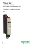
Rear view
Connector :
- for direct connection of the display module to the speed
controller
- for remote operation, the display module can be connected
via a cable provided in the VW3A58103 kit.
Access locking switch :
- position
: Settings and configuration not accessible
- position
: Settings accessible
- position
: Settings and configuration accessible
60
ATV 58 EN
60
22/05/01, 9:23
Practical Advice / Minimum Setup
Practical advice :
Before starting your programming, first fill in the configuration and settings record tables (at the end
of this document).
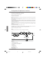
Programming the Altivar 58 is made easier by the use of internal sequence selections and
interlocks. In order to maximize this ease of use, we recommend that you access the menus in the
following order. Not all steps are essential in every case.
↓ LANGUAGE
MACRO-CONFIG
IDENTIFICATION
CONTROL (for 3-wire control only)
I/O
CONTROL
DRIVE
FAULT
↓ COMMUNICATION or APPLICATION if a card is used
ADJUST
CAUTION : The user must ensure that the programmed functions are compatible with the wiring
diagram used. This check is particularly important on the ready-assembled ATV-58E if the factory
configuration is modified; the diagram may also require modification.
Minimum setup :
This procedure can be used :
- in simple applications where the speed controller factory settings are suitable
- in installation phases where it is necessary to rotate the motor experimentally before
undertaking a full installation
Procedure :
1 - Follow the recommendations in the User's Manual supplied with the speed controller, most
importantly setting the 50/60 Hz selector switch to the nominal frequency of the motor.
2 - Ensure that the factory macro-configuration is suitable, otherwise change it in the «MACROCONFIG» menu.
3 - For speed controllers with power ratings greater than 7.5 kW at 200/240 V and 15 kW at
380/500 V in "standard torque" applications, configure the power in the «IDENTIFICATION»
menu.
4 - To ensure the required level of safety, check that the wiring diagram is compatible with
the macro-configuration, otherwise modify the diagram.
5 - Check in the «DRIVE» menu that the factory parameters are compatible with those given
on the motor rating plate, otherwise modify them.
6 - In the «DRIVE» menu, perform an auto tune.
7 - If necessary, adjust the parameters in the «ADJUST» menu (ramps, thermal current, etc).
61
ATV 58 EN
61
22/05/01, 9:23
E
N
G
L
I
S
H
Unlocking Menus Before Programming
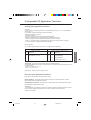
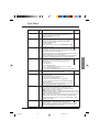
Level of access / Operating mode
The position of the selector switch offers three levels of access to the menus according to the
operating phase of your machine. Access to the menus can also be locked using an access code
(see the Files menu).
Position
Display : use during operating phases
- LANGUAGE menu : To select the dialog language
- MACRO-CONFIG menu : To display the macro-configuration
- IDENTIFICATION menu : To display the speed controller voltage and power
- DISPLAY menu : To display the electrical values, the operating phase or a fault
Position
Display and settings : use during setup phases
- To perform all the operations which are possible in level 0
- ADJUST menu : To set all the parameters which can be accessed while the motor
is rotating
E
N
G
L
I
S
H
Position
Total unlock : use during programming phases
- To perform all the operations which are possible in levels 0 and 1
- MACRO-CONFIG menu : To change the macro-configuration.
- IDENTIFICATION menu : To change the power in "standard torque" or "high torque" mode,
for the ratings governed by this parameter.
- DRIVE menu : To adjust the performance of the motor-speed controller unit
- CONTROL menu : To configure control of the speed controller, for control via the terminals,
the display module or the integrated RS485 serial link
- I/O menu : To change the I/O assignment
- FAULT menu : To configure the motor and speed controller protection and behavior in the
event of a fault
- FILES menu : To save and restore the speed controller configurations stored in the display
module, return to the factory settings or protect your configuration
- COMMUNICATION menu, if a communication card is installed : To adjust the parameters
of a communication protocol
- APPLICATION menu, if a «client application» card is installed. Please refer to the
documentation specific to this card.
62
ATV 58 EN
62
22/05/01, 9:23
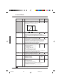
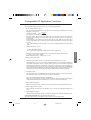
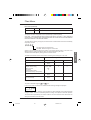
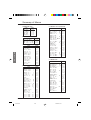
Access to Menus
The number of menus which can be accessed depends on the position of the access locking
switch.
Each menu is made up of a number of parameters.
Initial
power-up
Subsequent
power-ups
LnG
LANGUAGE
ESC
CFG
MACRO-CONFIG
rEF
0.37 kW 200/240 V
Identification
SUP
E
N
G
L
I
S
H
1-DISPLAY
SEt
2-ADJUST
drC
3-DRIVE
CtL
4-CONTROL
5-I/O
I-O
The PROG
indication is
displayed on
the display module
FLt
6-FAULT
FLS
7-FILES
can only be accessed if
the «client application»
card is installed
APP
8-APPLICATION
SL
8-COMMUNICATION
can only be accessed if
the protocol card is
installed
CAUTION : If an access code has already been programmed, it may be impossible to modify
some menus, these may not even be visible. In this case, see the section entitled “FILES menu”
explaining how to enter the access code.
63
ATV 58 EN
63
22/05/01, 9:23
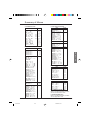
Access to Menus - Programming Principle
Language :
This menu can be accessed whatever position the access switch is in, and can be modified in
stop or run mode.
Example :
ENT
LnG
LnG
LANGUAGE
English
LnG
Italiano
Save the new
selection
ESC
Return to the previously
saved selection
ENT
E
N
G
L
I
S
H
ESC
LnG
LnG
Italiano
English
Possible selections : English (factory setting), French, German, Spanish, Italian.
Programming principle :
The principle is always the same, with 1 or 2 levels :
• 1 level : see the “language” example above.
• 2 levels : see the “acceleration ramp” example below.
ENT
SEt
ENT
ACC
Acceleration
2.ADJUST
ESC
3.0
s
Acceleration
s
(or
Increase
Decrease)
3.1
Acceleration
ESC
s
Save the
new value
Return to the
previous value
ESC
ENT
3.1
Acceleration
s
64
ATV 58 EN
64
3.0
Acceleration
22/05/01, 9:23
s
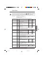
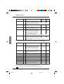
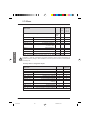
Macro-Configurations
This parameter can always be displayed but can only be modified in programming mode (access
switch in position
) and in stop mode with the speed controller locked.
It can be used to automatically configure an application-specific function. Three application-specific
functions are available.
- Handling (Hdg)
- Variable torque for pump and fan applications (VT)
- General use (GEn)
A macro-configuration automatically assigns the I/O and parameters, activating the functions
required for the application. The parameters related to the programmed functions are available.
Factory setting : Handling
Speed controller :
I/O assignment according to the macro-configuration
Hdg : Handling
GEn : Gen Use.
VT : Var. Torque
Logic input LI1
forward
forward
forward
Logic input LI2
reverse
reverse
reverse
Logic input LI3
2 preset speeds
jog operation
reference switching
Logic input LI4
4 preset speeds
freewheel stop (1)
injection braking
Analog input AI1
summing ref.
summing ref.
speed ref. 1
Analog input AI2
summing ref.
summing ref.
speed ref. 2
Relay R1
controller fault
controller fault
controller fault
Relay R2
downstr. contactor ctrl mot. therm. state reached freq. setpoint reached
E
N
G
L
I
S
H
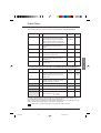
Extension cards :
I/O assignment according to the macro-configuration
Hdg : Handling
GEn : Gen Use.
VT : Var. Torque
Logic input LI5
8 preset speeds
clear fault
freewheel stop (1)
Logic input LI6
clear fault
limit torque
ramp switching
Analog input AI3
or
Inputs A, A+, B, B+
summing ref.
summing ref.
NO
speed feedback
speed feedback
speed feedback
Logic output LO
current thresh reached downstr. contactor ctrl high speed reached
Analog output AO
motor frequency
motor frequency
motor frequency
(1) In order to start, the logic input must be linked to the + 24 V (function active at 0).
CAUTION : Ensure that the programmed macro-configuration is compatible with the wiring
diagram used. This check is particularly important on the ready-assembled ATV-58E if the
factory configuration is modified; the diagram may also require modification.
65
ATV 58 EN
65
22/05/01, 9:23
Macro-Configurations
Modification of the macro-configuration requires double confirmation as it results in
automatic assignment of functions and a return to factory settings.
The following screen is displayed :
CHG
ENT to confirm the modification
ESC to return to the previous configuration
Validate? ENT/ESC
Customizing the configuration :
The configuration of the speed controller can be customized by changing the I/O assignment in
the I/O menu which can be accessed in programming mode (access switch in position
).
This customization modifies the displayed macro-configuration value :
CFG
is displayed.
CUS:Customize
E
N
G
L
I
S
H
66
ATV 58 EN
66
22/05/01, 9:23
Drive Identification
Drive identification
This parameter can always be displayed. It indicates the speed controller power and voltage as
indicated on the identification label.
rEF
0.37 kW 200/240 V
The power is displayed in kW if the 50/60 Hz selector switch on the
speed controller is set to 50 Hz, and in HP if it is set to 60 Hz.
For speed controllers rated above 7.5 kW at 200/240 V and 15 kW at 380/500 V :
The rating is different according to whether it is a standard torque or high torque application. The
speed controllers are supplied factory set at "high torque". "Standard torque" configuration is
obtained in the following way :
ENT
22 kW rEF
rEF flashes
22 kW
380/500 V
rEF flashes
rEF
380/500 V
+30 kW
rEF
380/500 V
ou ESC
ESC
ENT
+30 kW
rEF
380/500 V
+30 kW
E
N
G
L
I
S
H
rEF
380/500 V
ESC
In "standard torque" applications the + sign precedes the power in kW.
To return to "high torque" configuration, perform the same procedure.
"Standard torque" or "high torque" configuration preconfigures the "factory setting" of certain
parameters :
• Drive menu : UnS, nCr, nSP, COS, tUn
• Adjust menu : ItH, IdC.
Changing from one to the other of these torque configurations therefore results in all
these parameters returning to factory settings.
67
ATV 58 EN
67
22/05/01, 9:24
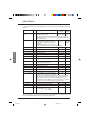
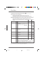
Display Menu
Display menu (selection of parameter displayed during operation)
The following parameters can be accessed whatever position the access switch is in, in stop or
run mode.
Label
Var. State
Code Function
--rdY
rUn
ACC
dEC
CLI
dCb
nSt
Obr
Freq. Ref.
E
N
G
L
I
S
H
Unit
State of the speed controller : indicates a fault or
the motor operating phase :
rdY = speed controller ready,
rUn = motor in steady state or run command present and zero
reference,
ACC = accelerating,
dEC = decelerating,
CLI = current limit,
dCb = injection braking,
nSt = freewheel stop control,
Obr = braking by adapting the deceleration ramp (see the “drive”
menu).
FrH Frequency reference
Hz
Output Freq. rFr Output frequency applied to the motor
Hz
Motor Speed SPd Motor speed estimated by the speed controller
rpm
MotorCurrent LCr Motor current
A
Mach. speed USP Machine speed estimated by the speed controller. This is
proportional to rFr, according to a coefficient USC which can be
regulated in the adjust menu. Displays a value corresponding to
the application (metres / second, for example).
Caution, if USP becomes greater than 9999 the display is
divided by 1000.
–
Output power OPr Power supplied by the motor, estimated by the controller.
100 % corresponds to nominal power.
%
MainsVoltage ULn Line voltage
V
MotorThermal tHr Thermal state : 100% corresponds to the nominal thermal state
of the motor. Above 118%, the speed controller triggers an OLF
fault (motor overload)
%
DriveThermal tHd Thermal state of the speed controller : 100% corresponds to the
nominal thermal state of the speed controller. Above 118%, the
speed controller triggers an OHF fault (speed controller
overheating). It can be reset below 70 %.
%
Last Fault
LFt Displays the last fault which occurred.
-
Freq. Ref.
LFr This adjustment parameter appears instead of the FrH parameter Hz
when the speed controller control via the display module is
activated : LCC parameter in the control menu.
Consumption APH Energy consumed.
Run time
kWh
or
MWh
rtH perating time (motor powered up) in hours.
hrs
68
ATV 58 EN
-
68
22/05/01, 9:24
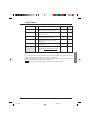
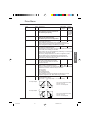
Adjust Menu
This menu can be accessed when the switch is in positions
and
. Adjustment parameters
can be modified in stop mode OR during operation. Ensure that any changes made during
operation are not dangerous; changes should preferably be made in stop mode.
The list of adjustment parameters is made up of a fixed and a changeable part which varies
according to :
- the selected macro-configuration
- the presence of an I/O extension card
- the reassignment of I/O
The following parameters can always be accessed in all the macro-configurations.
Label
Freq. Ref.
Code Description
Adjustment
range
- Hz LFr Appears when control via the display
module is activated :
LCC parameter in the control menu
Acceleration - s ACC Acceleration and deceleration
Deceleration - s dEC ramp times
Ranges 0 to motor nominal
frequency (FrS)
Factory
setting
LSP to HSP
0.05 to 999.9
0.05 to 999.9
3s
3s
Accelerate 2 - s AC2 2nd acceleration
0.05 to 999.9
5s
ramp
Decelerate 2 - s dE2 2nd deceleration
0.05 to 999.9
5s
ramp
These parameters can be accessed if the ramp switching
threshold (parameter Frt) is other than 0 Hz or if a logic
input is assigned to ramp switching.
E
N
G
L
I
S
H
Low Speed
- Hz LSP Low speed
0 to HSP
0 Hz
High Speed
- Hz HSP High speed : ensure that this
setting is correct for the motor and
the application.
LSP to tFr
50 / 60 Hz
acc. to
the switch
Gain
- %
Stability
-
FLG Frequency loop gain : used to
0 to 100
20
adapt the rapidity of the machine
speed transients according to the dynamics.
For high resistive torque, high inertia or fast cycle machines,
increase the gain gradually.
% StA Used to adapt the return to steady
0 to 100
state after a speed transient
according to the dynamics of the machine.
Gradually increase the stability to avoid any
overspeed.
ThermCurrent - A ItH Current used for motor thermal
protection. Set ItH to the nominal
current on the motor rating
plate.
20
0.25 to 1.36 According
In (1)
to
controller
rating
DC Inj. Time-
s tdC DC injection braking time.
0 to 30 s
If this is increased to more than 30 s,
Cont
"Cont" is displayed, permanent
DC injection.
The injection becomes equal to SdC after 30 seconds.
DC stop.curr-
A SdC Injection braking current applied
0.1 to 1.36
Acc. to
after 30 seconds if tdC = Cont.
In (1)
contr. rating
Check that motor will withstand this curr. without overheating
0.5 s
(1) In corresponds to the speed controller nominal current indicated in the catalog and on the
speed controller identification label for high torque applications.
69
ATV 58 EN
69
22/05/01, 9:24
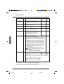
Adjust Menu
Label
Code
Jump Freq.
Adjustment
range
Factory
setting
- Hz JPF Skip frequency : prohibits prolonged
0 to HSP
0 Hz
operation over a frequency range of
+/-2.5 Hz around JPF. This function can be used to prevent a
critical speed which causes resonance.
Jump Freq.2- Hz
JF2 Second skip frequency: Same function
as JPF, for a second frequency value
0 to HSP
0 Hz
Jump Freq.3- Hz
JF3 Third skip frequency: Same function
as JPF, for a third frequency value
0 to HSP
0 Hz
LSP Time
tLS Operating time at low speed.
0 to 999.9
After operating at LSP for a given time,
the motor is stopped automatically.
The motor restarts if the frequency
reference is greater than LSP and if a
run command is still present.
Caution : value 0 corresponds to an unlimited time
0
(no
time
limit)
USC Coefficient applied to parameter rFr
0.01 to 100
(output frequency applied to the motor),
the machine speed is displayed via parameter USP
USP = rFr x USC
1
-
s
Machine Coef.
E
N
G
L
I
S
H
Description
The following parameters can be accessed in the ‘handling’ macro-configuration
Label
Code Description
IR Compens. -
Slip Comp. -
%
Adjustment
range
Factory
setting
% UFr Used to adjust the default value or the
value measured during auto-tuning.
The adjustment range is extended to
800% if the SPC parameter (special
motor) is set to “Yes” in the drive menu.
0 to 150%
or
0 to 800%
100%
SLP Used to adjust the slip compensation
value fixed by the motor nominal
speed.
0 to 150%
100%
Preset Sp.2- Hz
SP2 2nd preset speed
LSP to HSP
10 Hz
Preset Sp.3- Hz
SP3 3rd preset speed
LSP to HSP
15 Hz
Preset Sp.4- Hz
SP4 4th preset speed
LSP to HSP
20 Hz
Preset Sp.5- Hz
SP5 5th preset speed
LSP to HSP
25 Hz
Preset Sp.6- Hz
SP6 6th preset speed
LSP to HSP
30 Hz
Preset Sp.7- Hz
SP7 7th preset speed
LSP to HSP
35 Hz
Curr.Lev.Att- A
Ctd Current threshold above which the logic
output or the relay changes to 1
0 to 1.36
In (1)
1.36 In (1)
(1) In corresponds to the speed controller nominal current indicated in the catalog and on the
speed controller identification label for "high torque" applications.
Parameters in gray boxes appear if an I/O extension card is installed.
70
ATV 58 EN
70
22/05/01, 9:24
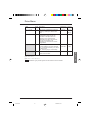
Adjust Menu
The following parameters can be accessed in the ‘general use’ macro-configuration
Label
Code Description
Adjustment
range
Factory
setting
IR Compens. -
% UFr Used to adjust the default value or the
measured value during auto-tuning.
The adjustment range is extended to
800% if the SPC parameter (special
motor) is set to “Yes” in the drive menu.
0 to 150%
or
0 to 800%
100%
Slip Comp.
-
% SLP Used to adjust the slip compensation
value fixed by the motor nominal
speed.
0 to 150%
100%
Jog Freq.
- Hz JOG Jog frequency
0 to 10 Hz
10 Hz
JOG Delay
-
s JGt Anti-repeat delay between two
consecutive jog operations
0 to 2 s
0.5 s
Therm.Det
-
% ttd Motor thermal state threshold above
which the logic output or the relay
changes to 1
0 to 118%
100%
Trq.Limit 2- %
tL2 Second torque limit level activated by
a logic input
0 to 200%
(1)
E
N
G
L
I
S
H
200%
The following parameters can be accessed in the ‘variable torque’ macro-configuration
Label
Code Description
DC Inj.curr -
U/f Profile
PI Prop.Gain
Adjustment
range
A IdC DC injection braking current.
After 30 seconds the injection current is
peak limited to 0.5 Ith if it is set at a
higher value
Factory
setting
0.10 to 1.36 Acc. to
In (2)
controller
rating
- % PFL Used to adjust the quadratic power
supply ratio when the energy saving
function has been inhibited
0 to 100%
rPG Proportional gain of the PI regulator
20%
0.01 to 100
1
PI Int.Gain - /s rIG Integral gain of the PI regulator
0.01 to
100 / s
1/s
PI Coeff.
FbS PI feedback multiplication coefficient
1 to 100
1
PI Inversion
PIC Reversal of the direction of correction of
the PI regulator no : normal
yes : reverse
No - Yes
No
(1) 100% corresponds to the nominal torque of a motor with a power rating equal to that
associated with the speed controller in high torque applications.
(2) In corresponds to the speed controller nominal current indicated in the catalog and on the
speed controller identification label for "high torque" applications.
Parameters in gray boxes appear if an I/O extension card is installed.
71
ATV 58 EN
71
22/05/01, 9:24
Adjust Menu
The following parameters can be accessed once the I/O have been reassigned on the basic
product.
Label
Accel. 2
Decel. 2
Code Description
-
DC Inj.curr -
E
N
G
L
I
S
H
Adjustment
range
Factory
setting
s AC2 2nd acceleration ramp
0.05 to 999.9
5s
s dE2 2nd deceleration ramp
0.05 to 999.9
5s
These parameters can be accessed if the ramp switching time
(parameter Frt) is other than 0 Hz or if a logic input is assigned
to ramp switching.
A IdC DC injection braking current
0.10 to 1.36 Acc. to
This parameter can be accessed if a
In (1)
controller
logic input is assigned to DC injection
rating
stopping.
After 30 seconds the injection current
is peak limited to 0.5 Ith if it is set at a higher value
Preset Sp.2 - Hz SP2 2nd preset speed
LSP to HSP
Preset Sp.3 - Hz SP3 3rd preset speed
LSP to HSP
15 Hz
Preset Sp.4 - Hz SP4 4th preset speed
LSP to HSP
20 Hz
Preset Sp.5 - Hz SP5 5th preset speed
LSP to HSP
25 Hz
Preset Sp.6 - Hz SP6 6th preset speed
LSP to HSP
30 Hz
Preset Sp.7 - Hz SP7 7th preset speed
LSP to HSP
35 Hz
0 to 10 Hz
10 Hz
0 to 2 s
0.5 s
0 to 10 Hz
0 Hz
0 to 1.36In(1)
0A
Jog Freq.
- Hz JOG Jog frequency
JOG Delay
-
s JGt Anti-BrkLgSeqFlwd delay between two
consecutive jog operations
BrReleaseLev- Hz brL Brake release frequency
BrRelease I -
A Ibr Brake release current
BrReleasTime-
s brt Brake release time
10 Hz
0 to 5 s
0s
BrEngage Lev- Hz bEn Brake engage frequency
0 to LSP
0 Hz
BrEngageTime- Hz bEt Brake engage time
0 to 5 s
0s
TripThreshNST-Hz FFt Freewheel stop trip threshold: When a
0 to HSP
0 Hz
stop on ramp or fast stop is requested,
the type of stop selected is activated until the speed falls below
this threshold. Below this threshold, freewheel stop is activated.
This parameter can only be accessed if the R2 relay is not
assigned to the “BLC: Brake Logic” function, and if an “on ramp”
or “fast” type stop has been selected in the drive menu.
PI Prop.Gain
rPG Proportional gain of the PI regulator
PI Int.Gain
rIG Integral gain of the PI regulator
PI Coeff.
FbS PI feedback multiplication coefficient
1 to 100
1
PI Inversion
PIC Reversal of the direction of correction of
the PI regulator no : normal
yes : reverse
No - Yes
No
0.01 to 100
1
0.01 to 100/s
1/s
(1) In corresponds to the speed controller nominal current indicated in the catalog and on the
speed controller identification label for "high torque" applications.
72
ATV 58 EN
72
22/05/01, 9:24
Adjust Menu
Label
Code Description
Adjustment
range
Freq.Lev.Att- Hz Ftd Motor frequency threshold above
which the logic output changes to 1
Freq.Lev.2
- Hz
F2d Same function as Ftd, for a second
frequency value
Curr.Lev.Att-
A Ctd Current threshold above which the logic
output or the relay changes to 1
ThermLev.Att-
Trq.Limit 2
Tacho Coeff.
Factory
setting
LSP to HSP 50/60 Hz
LSP to HSP 50/60 Hz
0.25 to 1.36 In
(1)
1.36 In
(1)
% ttd Motor thermal state threshold above
which the logic output or the relay
changes to 1
0 to 118%
100%
- % tL2 Second torque limit level activated by
a logic input
0 to 200%
(2)
200%
1 to 2
1
dtS Multiplication coefficient of the feedback
associated with tachogenerator function :
9
dtS =
tacho voltage at HSP
(1) In corresponds to the speed controller nominal current indicated in the catalog and on the
speed controller identification label for "high torque" applications.
(2) 100% corresponds to the nominal torque of a motor with a power rating equal to that associated
with the speed controller for "high torque" applications.
Parameters in gray boxes appear if an I/O extension card is installed.
73
ATV 58 EN
73
22/05/01, 9:24
E
N
G
L
I
S
H
Drive Menu
This menu can be accessed when the switch is in position
.
The parameters can only be modified in stop mode with the speed controller locked.
Drive performance can be optimized by :
- entering the values given on the rating plate in the drive menu
- performing an auto-tune operation (on a standard asynchronous motor)
When using special motors (motors connected in parallel, tapered rotor brake motors,
synchronous or synchronized asynchronous motors, rheostatic rotor asynchronous motors) :
- Select the “Hdg : Handling” or the “GEn : General Use” macro-configuration.
- Set the “SPC” Special motor parameter to “Yes” in the drive menu.
- Adjust the “UFr” IR compensation parameter in the adjust menu to obtain satisfactory
operation.
Label
Code Description
Adjustment
range
Nom.Mot.Volt - V UnS Nominal motor voltage given on the
rating plate
The adjustment range depends on the
speed controller model : ATV58••••M2
ATV58••••N4
E
N
G
L
I
S
H
Nom.Mot.Freq- Hz FrS Nominal motor frequency given on the
rating plate
Factory
setting
200 to 240V
230 V
200 to 500 V 400/460V
according
to position
of 50/60Hz
switch
10 to 500 Hz 50/60Hz
according
to position
of 50/60Hz
switch
Nom.Mot.Curr - A nCr Nominal motor current given on the
rating plate
0.25 to
1.36 In (1)
acc. to
controller
rating
Nom.MotSpeed-rpm nSP Nominal motor speed given on the
rating plate
0 to
9999 rpm
acc. to
controller
rating
0.5 to 1
acc. to
controller
rating
Mot. Cos Phi
COS Motor Cos Phi given on the rating
plate
Auto Tuning
tUn Used to auto-tune motor control once
No - Yes
No
this parameter has been set to “Yes”.
Once auto-tuning is complete, the parameter automatically returns
to “Done”, or to “No” in the event of a fault.
Caution : auto-tuning is only performed if no command has been
activated. If a "freewheel stop" or "fast stop" function is assigned
to a logic input, this input must be set to 1 (active at 0).
(1) In corresponds to the speed controller nominal current indicated in the catalog and on the
speed controller identification label for "high torque" applications.
74
ATV 58 EN
74
22/05/01, 9:24
Drive Menu
Label
Code Description
Max. Freq.
Adjustment
range
- Hz tFr Maximum output frequency.
The maximum value is a function of
the switching frequency
Factory
setting
10 to 500 Hz 60/72Hz
according
to position
of 50/60Hz
switch
Energy Eco
nLd Optimizes motor efficiency.
Can only be accessed in the
variable torque macro-configuration.
I lim. Adapt
Fdb Adaptation of the current limit according
No-Yes
No
to the output frequency.
This parameter only appears in the "variable torque" VT
macro-configuration (ventilation applications where the load
curve changes according to the density of the gas).
DecRampAdapt
brA Activation of this function is used to
No-Yes
No
increase the deceleration time
automatically if this has been set to too low a value for the inertia
of the load, thus avoiding an ObF fault.
This function may be incompatible with positioning on a ramp and
with the use of a braking resistor.
The factory setting depends on the macro-configuration used :
No for handling, Yes for variable torque and general use.
If relay R2 is assigned to the brake sequence function, the
parameter brA remains locked on No.
No-Yes
Yes
SwitchRamp2- Hz
Frt Ramp switching frequency.
Once the output frequency exceeds
Frt, the ramp times taken into account
are AC2 and dE2.
Type of stop
Stt Type of stop:
STN - FST
STN
When a stop is requested, the type
NST - DCI
of stop is activated until the Ftt threshold (adjust menu) is reached.
Below this threshold, freewheel stop is activated.
Stn: On ramp
Fst: Fast stop
Nst: Freewheel stop
Dci: DC injection stop
This parameter cannot be accessed if the R2 relay or a logic
output is assigned to the “BLC: Brake Logic” function.
Ramp Type
rPt Defines the shape of the acceleration
LIN - S - U
and deceleration ramps.
LIN : linear S : S-shape ramp U : U-shape ramp
f (Hz)
S-shape ramps
0 Hz
LIN
f (Hz)
GV
GV
0
t
t2
0
t
t2
t1
The curve coefficient is fixed,
with t2 = 0.6 x t1
with t1 = set ramp time.
t1
f (Hz)
U-shape ramps
0 to HSP
f (Hz)
GV
GV
0
t2
t1
t
0
t2
t1
t
The curve coefficient is fixed,
with t2 = 0.5 x t1
with t1 = set ramp time.
75
ATV 58 EN
75
22/05/01, 9:24
E
N
G
L
I
S
H
Drive Menu
Label
Code Description
DecRAmpCoeff
dCF Deceleration ramp time reduction
coefficient when the fast stop function
is active.
Trq.Limit
_ %
Int. I Lim -
A
Adjustment
range
Factory
setting
1 to 10
4
tLI The torque limit is used to limit the
maximum motor torque.
0 to 200%
(1)
200%
CLI The current limit is used to limit
motor overheating.
0 to
1.36 In (2)
1.36 In
Auto DC Inj.
AdC Used to deactivate automatic DC
injection braking on stopping.
No-Yes
Yes
Motor P Coef
PCC Defines the relationship between the
speed controller nominal power and a
less powerful motor when a logic
input has been assigned to the motor
switching function.
0.2 to 1
1
Sw Freq. Type
SFt Used to select a low switching
LF-HF1-HF2
frequency (LF) or a high switching
frequency (HF1 or HF2). HF1 switching is designed
for applications with a low load factor without derating
the speed controller. If the thermal state of the speed
controller exceeds 95 %, the frequency automatically
changes to 2 or 4 kHz depending on the speed
controller rating. When the thermal state of the speed
controller drops back to 70 %, the selected switching
frequency is re-established. HF2 switching is designed
for applications with a high load factor with derating of
the speed controller by one rating : the drive
parameters are scaled automatically (torque limit,
thermal current, etc).
Modifying this parameter results in the
following parameters returning to factory
settings :
• nCr, CLI, Sfr, nrd (Drive menu)
• ItH, IdC, Ibr, Ctd (Adjust menu).
Sw Freq. -
SFr Used to select the switching frequency.
0.5-1-2-4acc. to
The adjustment range depends on the
8-12-16kHz controller
SFt parameter.
rating
If SFt = LF : 0.5 to 2 or 4 kHz acc. to the controller rating
If SFt = HF1 or HF2 : 2 or 4 to 16 kHz acc. to the controller rating
E
N
G
L
I
S
H
kHz
LF
The maximum operating frequency (tFr) is
limited according to the switching frequency :
SFr(kHz) 0.5 1
2
4
8 12 16
tFr (Hz)
62 125 250 500 500 500 500
(1) 100% corresponds to the nominal torque of a motor with a power rating equal to that
associated with the speed controller for "high torque" applications.
(2) In corresponds to the speed controller nominal current indicated in the catalog and on the
speed controller identification label for "high torque" applications.
76
ATV 58 EN
76
22/05/01, 9:24
Drive Menu
Label
Code Description
Adjustment
range
Factory
setting
Noise Reduct
nrd This function modulates the switching
frequency randomly to reduce motor
noise.
No-Yes
Yes (1)
Special motor
SPC This function with "yes" extends
the adjustment range for the UFr
parameter in the adjust menu for
adaptation to the special motors
mentioned at the start of this section.
Can only be accessed in the
"Handling" and "General use" macroconfigurations.
No-Yes
No
PG Type
PGt Defines the type of sensor used when an
encoder feedback I/O card is installed :
INC : incremental encoder (A, A+, B, B+
are hard-wired)
DET : detector (only A is hard-wired)
INC-DET
DET
1 to 1024
11
Num. Pulses
PLS Defines the number of pulses for one
rotation of the encoder.
No (2)
E
N
G
L
I
S
H
(1) If SFt = LF,
(2) If SFt = HF1 or HF2
Parameters in gray boxes appear if an I/O extension card is installed.
77
ATV 58 EN
77
22/05/01, 9:24
Control Menu
This menu can be accessed when the switch is in position
modified in stop mode with the speed controller locked.
Label
Code Description
TermStripCon
tCC Configuration of terminal control :
2-wire or 3-wire control.
. The parameters can only be
Adjustment
range
Factory
setting
2W- 3W
2-wire / 3-wire
2W
Modification of this parameter requires double
confirmation as it results in reassignment of the logic inputs.
By changing from 2-wire control to 3-wire control, the logic input
assignments are shifted by one input. The LI3 assignment
in 2-wire control becomes the LI4 assignment in 3-wire control.
In 3-wire control, inputs LI1 and LI2 cannot be reassigned.
I/O
Handling
General use
Variable torque
LI1
STOP
STOP
STOP
LI2
RUN forward
RUN forward
RUN forward
LI3
RUN reverse
RUN reverse
RUN reverse
LI4 2 preset speeds
jog operation
ref. switching
LI5 4 preset speeds
freewheel stop
injection braking
LI6 8 preset speeds
clear faults
freewheel stop
The I/O with a gray background can be accessed if an I/O
extension card has been installed.
E
N
G
L
I
S
H
3-wire control (pulse control : one pulse is sufficient to control
start-up). This option inhibits the "automatic restart" function.
Wiring example :
LI1 : stop
LI2 : forward
LIx : reverse
ATV58 control terminals
24 V LI1 LI2 LIx
This option only appears if 2-wire control is configured.
Label
Code Description
Type 2 Wire
tCt Defines 2-wire control :
Adjustment
range
Factory
setting
LEL-TRN-PFo
LEL
- according to the state of the logic inputs (LEL : 2-wire)
- according to a change in state of the logic inputs
(TRN : 2-wire trans.)
- according to the state of the logic inputs with forward always
having priority over reverse (PFo : Priorit. FW)
Wiring example :
ATV58 control terminals
24 V LI1 LIx
LI1 : forward
LIx : reverse
78
ATV 58 EN
78
22/05/01, 9:24
Control Menu
Label
Code Description
RV Inhib.
rln • Inhibition of operation in the opposite
direction to that controlled by the logic
inputs, even if this reversal is required by
a summing or process control function.
• Inhibition of reverse if it is controlled by
the FWD/REV key on the display module.
deadb./pedst
bSP Management of operation at
low speed :
Adjustment
range
Factory
setting
No - Yes
No
No
BNS:Pedestal
BLS:Deadband
No
F : motor frequency
HSP
No
LSP
Reference
0
100 %
E
N
G
L
I
S
H
F : motor frequency
HSP
Pedestal
(BNS)
LSP
Reference
0
100 %
F : motor frequency
HSP
Deadband
(BLS)
LSP
Reference
0
100 %
AI2 min Ref.- mA CrL Minimum value of the signal on input AI2 0 to 20 mA
AI2 Max. Ref- mA CrH Maximum value of the signal on input AI2 4 to 20 mA
These two parameters are used to define
the signal sent to AI2. There are several
configuration possibilities, one of which is
to configure the input for a 0-20 mA,
4-20 mA, 20-4mA, etc signal.
4 mA
20 mA
Frequency
HSP
LSP
0
CrL
CrH
20
AI 2
(mA)
79
ATV 58 EN
79
22/05/01, 9:24
Control Menu
Label
Code Description
Adjustment
range
Factory
setting
AO Min. Val- mA
AO Max. Val- mA
AOL Min. value of the signal on output AO
0 to 20 mA
0 mA
AOH Max. value of the signal on output AO
0 to 20 mA
20 mA
These two parameters are used to define the output signal on AO.
Eg. : 0-20 mA, 4-20 mA, 20-4mA, etc
Parameter
Max
AO (mA)
0
AOL
E
N
G
L
I
S
H
AOH
20
Save Ref.
Str Associated with the +/- speed function,
NO-RAM-EEP
NO
this function is used to save the reference :
when the run commands disappear (save in RAM)
or when the line supply disappears (save in EEPROM)
On the next start-up, the speed reference is the last reference
saved.
Keypad Comm.
LCC Used to activate speed controller control via
No-Yes
No
the display module. The STOP/RESET, RUN
and FWD/REV keys are active. The speed reference is given by
the parameter LFr. Only the freewheel stop, fast stop and DC
injection stop commands remain active at the terminals.
If the speed controller / display module connection is cut,
the speed controller locks in an SLF fault.
STOP Priorit
PSt This function gives priority to the STOP
No-Yes
Yes
key irrespective of the control channel
(terminals or fieldbus).
To set the PSt parameter to "No" :
1 - Display "No".
2 - Press the "ENT" key.
3 - The speed controller displays
"See manual"
4 - Press ▲ then ▼ then "ENT".
For applications with continuous processes, it is advisable
to configure the key as inactive (set to "No").
DriveAddress
Add Address of the speed controller when it is
0 to 31
0
controlled via the display module port
(with the display module and programming terminal removed)
BdRate RS485
tbr ransmission speed via RS485 serial link.
4800 Bits / seconde
9600 Bits / seconde
19200 Bits / seconde
Reset counters
rPr KWh or operating time reset to 0
No-APHNo
No: No
RTH
APH: KWh reset to 0
RTH: Operating time reset to 0
APH and RTH are active immediately. The parameter then
automatically returns to NO.
Press “ENT” to confirm the reset to 0 command.
4800960019200
Parameters in gray boxes appear if an I/O extension card is installed.
80
ATV 58 EN
80
22/05/01, 9:24
19200
I/O Menu
This menu can be accessed when the switch is in position
.
The assignments can only be modified in stop mode with the speed controller locked.
Label
Code Function
LI2 Assign.
LI2
See the summary table and description of the functions
The inputs and outputs available in the menu depend on the I/O cards installed (if any) in the
speed controller, as well as the selections made previously in the control menu.
The “factory” configurations are preassigned by the selected macro-configuration.
Summary table of the configurable input assignments (exc. 2-wire / 3-wire option)
I/O extension option cards
2 logic inputs LI5-LI6
Speed controller without option
NO:Not assigned
RV :Reverse
RP2:Switch Ramp2
JOG
+SP: + Speed
-SP: - Speed
3 logic inputs LI2 to LI4
(Not assigned)
X
(Run reverse)
X
(Ramp switching)
X
(Jog operation)
X
(+ speed)
X
(- speed)
X
PS2: 2 Preset SP
(2 preset speeds)
X
PS4: 4 Preset SP
(4 preset speeds)
X
PS8: 8 Preset SP
(8 preset speeds)
X
NST:Freewhl Stop
(Freewheel stop)
X
DCI:DC inject.
FST:Fast stop
CHP:Multi. Motor
(Injection stop)
X
(Fast stop)
X
(Motor switching)
X
TL2:Trq.Limit 2
(Second torque limit)
X
FLO:Forced Local
(Forced local mode)
X
(Clearing faults)
X
RST:Fault Reset
RFC:Auto/manu
(Reference switching)
X
ATN:Auto-tune
(Auto-tuning)
X
PAU:PID Auto/Manu
(PID Auto/Manu) If one AI = PIF
X
PR2:PID 2 Preset
(2 preset PID setpoints) If one AI = PIF
X
PR2:PID 4 Preset
(4 preset PID setpoints) If one AI = PIF
X
TLA:Torque limit
(Torque limitation by AI) If one AI = ATL
X
E
N
G
L
I
S
H
If a logic input is assigned to "Freewheel stop" or "Fast stop", start-up can only be performed by
linking this input to the +24V, as these stop functions are active when inputs are at state 0.
81
ATV 58 EN
81
22/05/01, 9:24
I/O Menu
I/O extension
option cards
Speed controller without option
Encoder
input (1)
A+, A-,
B+, B-
X
X
X
Analog
input
AI2
NO:Not assigned
E
N
G
L
I
S
H
Analog
input
AI3
(Not assigned)
X
FR2:Speed Ref2
(Speed reference 2)
X
SAI:Summed Ref.
(Summing reference)
X
X
X
PIF:PI Regulator
(Pl regulator feedback)
X
PIM:PID Man.ref.
(Manual PID speed reference)
If one AI = PIF
X
SFB:Tacho feedbk
(Tachogenerator)
X
PTC:Therm.Sensor
(PTC probes)
X
ATL:Torque Lim.
(Torque limit)
X
RGI:PG feedbk
(Encoder or sensor feedback)
X
(1) NB : The menu for assigning encoder input A+, A-, B+, B- is called "Assign AI3".
CAUTION : If relay R2 is assigned to the "brake sequence" function, AI3 is automatically assigned in the factory setting to Tacho Feedback, if the card is present. However, it is still possible
to reassign AI3.
Summary table for configurable outputs
I/O extension
option card
Logic
output LO
Speed controller without option
NO:Not assigned
(Not assigned)
RUN:DriveRunning
(Speed controller running)
OCC:OutputCont.
(Downstream contactor control)
FTA:Freq Attain.
(Threshold freq. reached)
FLA:HSP Attained
(HSP reached)
CTA:I Attained
(Current threshold reached)
SRA:FRH Attained
(Frequency reference
reached)
TSA:MtrTherm Lvl
(Thermal threshold reached)
BLC:Brk Logic
(Brake sequence)
APL:4-20 mA loss
F2A:F2 Attained
Relay R2
X
X
X
X
X
X
X
X
X
82
X
(Loss of 4-20 mA signal)
X
X
(Second frequency threshold reached)
X
X
82
ATV 58 EN
X
X
X
X
X
X
X
22/05/01, 9:24
I/O Menu
Tableau récapitulatif des affectations de la sortie analogique
I/O extension option cards
Analog output AO
NO :Not assigned
(Not assigned)
X
OCR:Motor Curr.
(Motor current)
X
OFR:Motor Freq
(Motor speed)
X
ORP:Output ramp
(Ramp output)
X
TRQ:Motor torque
(Motor torque)
X
STQ:Signed Torq.
(Signed motor torque)
X
ORS:Signed ramp
OPS:PID ref.
OPF:PID Feedback
(Signed ramp output)
X
(PID setpoint output) If one AI = PIF
X
(PID feedback output) If one AI = PIF
X
(PID error output) If one AI = PIF
X
(PID integral output) If one AI = PIF
X
(Motor power)
X
OPE:PID Error
OPI:PID Integral
OPR:Motor power
THR:Motor Thermal
(Motor thermal state)
X
THD:Drive Thermal
(Drive thermal state)
X
Once the I/O have been reassigned, the parameters related to the function automatically
appear in the menus, and the macro-configuration indicates “CUS : Customize”.
Some reassignments result in new adjustment parameters which the user must not forget
to set in the adjust menu :
I/O
Assignments
Parameters to set
LI
RP2
Ramp switching
AC2 dE2
LI
JOG
Jog operation
JOG JGt
LI
PS4
4 preset speeds
SP2-SP3
LI
PS8
8 preset speeds
SP4-SP5-SP6-SP7
LI
DCI
Injection stop
IdC
LI
TL2
Second torque limit
tL2
LI
PR4
4 preset PID setpoints
PI2-PI3
AI
PIF
PI regulator
rPG-rIG-PIC-rdG-rEDPrG-PSr-PSP-PLr-PLb
AI
SFB
Tachogenerator
dtS
R2
BLC
Brake sequence
brL-Ibr-brt-bEn-bEt
LO/R2
FTA
Frequency threshold reached
Ftd
LO/R2
CTA
Current threshold reached
Ctd
LO/R2
TSA
Thermal threshold reached
ttd
LO/R2
PEE
PI error
PEr
LO/R2
PFA
PI feedback alarm
PAL-PAH
LO/R2
F2A
2 nd frequency threshold reached F2d
83
ATV 58 EN
83
22/05/01, 9:24
E
N
G
L
I
S
H
I/O Menu
Some reassignments result in new adjustment parameters being added which the user
must configure in the control, drive or fault menu :
I/O
LI
LI
LI
AI
A+, A-,
B+, BA+, A-,
B+, BR2
-SP
FST
RST
SFB
SAI
Assignments
- speed
Fast stop
Fault reset
Tachogenerator
Summing reference
Parameters to set
Str (control menu)
dCF (drive menu)
rSt (fault menu)
Sdd (fault menu)
PGt, PLS
(drive menu)
RGI
PG Feedback
BLC
Brake logic
PGt, PLS
(drive menu)
Stt (drive menu)
E
N
G
L
I
S
H
84
ATV 58 EN
84
22/05/01, 9:24
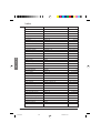
Configurable I/O Application Functions
Function compatibility table
Torque limitation via LI
Torque limitation via AI3
Speed regulation with
tachogenerator or encoder
Preset speeds
Jog operation
Fast stop
Freewheel stop
➞
DC injection
braking
Reference switching
+ / - speed
PI regulator
Summing inputs
DC injection
braking
The choice of application functions may be limited by incompatibility between certain functions.
Functions which are not listed in this table are fully compatible.
E
N
G
L
I
S
H
Summing inputs
PI regulator
➞
+ / - speed
Reference switching
➞
➞
Freewheel stop
➞
Fast stop
➞
Jog operation
➞
➞
Preset speeds
Speed regulation with
tachogenerator or encoder
Torque limitation via AI3
Torque limitation via LI
Incompatible functions
Compatible functions
Not applicable
Priority functions (functions which cannot be active simultaneously) :
➞
➞
The function indicated by the arrow has priority over the other.
Stop functions have priority over run commands.
Speed references via logic command have priority over analog setpoints.
85
ATV 58 EN
85
22/05/01, 9:24
Configurable I/O Application Functions
Logic input application functions
Operating direction : forward / reverse
Reverse operation can be disabled for applications requiring only a single direction of motor
rotation.
2-wire control :
Run and stop are controlled by the same logic input, for which state 1 (run) or 0 (stop), or a
change in state is taken into account (see the 2-wire control menu).
3-wire control :
Run and stop are controlled by 2 different logic inputs. LI1 is always assigned to the stop function.
A stop is obtained on opening (state 0).
The pulse on the run input is stored until the stop input opens.
During power-up or manual or automatic fault resetting, the motor can only be supplied with
power after a reset prior to the “forward”, “reverse”, and “injection stop” commands.
E
N
G
L
I
S
H
Ramp switching : 1st ramp : ACC, DEC ; 2nd ramp : AC2, DE2
Two types of activation are possible :
- activation of logic input LIx
- detection of an adjustable frequency threshold
If a logic input is assigned to the function, ramp switching can only be performed by this input.
Step by step operation (“JOG”) : Low speed operation pulse
If the JOG contact is closed and then the operating direction contact is actuated, the ramp is 0.1 s
irrespective of the ACC, dEC, AC2, dE2 settings. If the direction contact is closed and the JOG
contact is then actuated, the configured ramps are used.
Parameters which can be accessed in the adjust menu :
- JOG speed
- anti-repeat delay (minimum time between 2 “JOG” commands).
86
ATV 58 EN
86
22/05/01, 9:24
Configurable I/O Application Functions
+ / - speed : 2 types of operation are available
1 - Use of single action buttons : two logic inputs are required in addition to the operating direction(s).
The input assigned to the “+ speed” command increases the speed, the input assigned to the
“- speed” command decreases the speed.
This function accesses the Str save reference parameter in the Control menu.
2- Use of double action buttons : only one logic input assigned to + speed is required.
+ / - speed with double action buttons :
Description : 1 button pressed twice for each direction of rotation.
Each action closes a volt-free contact.
Release
(- speed)
Press
1
(speed
maintained)
Press
2
(+ speed)
forward
button
–
a
a and b
reverse
button
–
c
c and d
E
N
G
L
I
S
H
Wiring example :
ATV58 control terminals
LI1 LIx LIy
+ 24
LI1 : forward
LIx : reverse
LIy : + speed
b
a
d
c
Motor
frequency
LSP
0
LSP
Forward
Press 2
Press 1
0
b
a
a
b
a
a
a
a
a
Reverse
Press 2
Press 1
d
c
0
c
This type of +/- speed is incompatible with 3-wire control. In this case, the - speed function is
automatically assigned to the logic input with the highest index (for example : LI3 (+ speed), LI4
(- speed)).
In both cases of operation, the maximum speed is given by the references applied to the analog
inputs. For example, connect AI1 to +10V.
87
ATV 58 EN
87
22/05/01, 9:24
Configurable I/O Application Functions
Preset speeds
2, 4 or 8 speeds can be preset, requiring 1, 2, or 3 logic inputs respectively.
The following order of assignments must be observed : PS2 (LIx), then PS4 (LIy), then PS8 (LIz).
2 preset
speeds
4 preset
speeds
8 preset
speeds
Assign : LIx to PS2
Assign : LIx to PS2 then,
LIy to PS4
Assign : LIx to PS2
LIy to PS4, then LIz to PS8
LIx
0
1
E
N
G
L
I
S
H
speed reference
LSP+reference
HSP
LIy
0
0
1
1
LIx
0
1
0
1
speed reference
LSP+reference
SP2
SP3
HSP
LIz
0
0
0
0
1
1
1
1
LIy
0
0
1
1
0
0
1
1
LIx
0
1
0
1
0
1
0
1
speed reference
LSP+reference
SP2
SP3
SP4
SP5
SP6
SP7
HSP
To unassign the logic inputs, the following order must be observed : PS8 (LIz), then PS4 (LIy),
then PS2 (LIx).
Reference switching :
Switching of two references (AI1 reference and AI2 reference) by logic input command.
This function automatically assigns AI2 to speed reference 2.
Connection diagram
LI x + 24
COM
AI 1
+10
AI 2
Open contact, reference = AI2
Closed contact, reference = AI1
0-20mA
4-20mA
Freewheel stop
Causes the motor to stop using the resistive torque only. The motor power supply is cut.
A freewheel stop is obtained when the logic input opens (state 0).
DC injection stop
An injection stop is obtained when the logic input closes (state 1).
Fast stop :
Braked stop with the deceleration ramp time reduced by a reduction factor dCF which appears in
the drive menu.
A fast stop is obtained when the logic input opens (state 0).
88
ATV 58 EN
88
22/05/01, 9:24
Configurable I/O Application Functions
Motor switching :
This function is used to switch between two motors with different power ratings using the same
speed controller. An appropriate sequence must be installed on the speed controller output.
Switching is carried out with the motor stopped and the speed controller locked. The following
internal parameters are automatically switched by the logic command :
- nominal motor current
- injection current
- brake release current
This function automatically inhibits thermal protection of the second motor.
Accessible parameter : Motor power ratio (PCC) in the drive menu.
Second torque limit :
Reduction of the maximum motor torque when the logic input is active.
Parameter tL2 in the adjust menu.
Fault reset :
Two types of reset are available : partial or general (rSt parameter in the "fault" menu).
Partial reset (rSt = RSP) :
Used to clear the stored fault and reset the speed controller if the cause of the fault has disappeared.
Faults affected by partial clearing :
- line overvoltage
- DC bus overvoltage
- motor phase loss
- overhauling
- communication fault
- motor overload
- loss of 4-20mA
- external fault
- motor overheating
- serial link fault
- speed controller overheating
- overspeed
General reset (rSt = RSG) :
This inhibits all faults (forced operation) except SCF (motor short-circuit) while the assigned
logic input is closed.
Forced local mode :
Used to switch between line control mode (serial link) and local mode (controlled via the terminals
or via the display module).
Auto-tuning
When the assigned logic input changes to 1 an auto-tuning operation is triggered, in the same
way as parameter tUn in the "drive" menu.
CAUTION : Auto-tuning is only performed if no command has been activated. If a "freewheel
stop" or "fast stop" function is assigned to a logic input, this input must be set to 1 (active at 0).
Application : When switching motors, for example.
Auto-man PI, preset PI setpoints : PI operation (see page 90)
Torque limitation by AI:
This function can only be accessed if an analog input has been assigned to the torque limit
If the logic input is at 0, the torque is limited by setting tL1 or tL2.
If the logic input is at 1, the torque is limited by the analog input assigned to this function.
89
ATV 58 EN
89
22/05/01, 9:24
E
N
G
L
I
S
H
Configurable I/O Application Functions
Analog input application functions
Input AI1 is always the speed reference.
Assignment of AI2 and AI3
Summing speed reference : The frequency setpoints given by AI2 and AI3 can be summed with
AI1.
Speed regulation with tachogenerator : (Assignment on AI3 only with an I/O extension card
with analog input)
An external divider bridge is required to adapt the voltage of the tachogenerator. The maximum
voltage must be between 5 and 9 V. A precise setting is then obtained by setting the dtS parameter
available in the adjust menu.
PTC probe processing : (only with an I/O extension card with analog input). Used for the direct
thermal protection of the motor by connecting the PTC probes in the motor windings to analog
input AI3.
PTC probe characteristics :
Total resistance of the probe circuit at 20 °C = 750 Ω.
PI regulator : Used to regulate a process with a reference and a feedback given by a sensor. In
PI mode the ramps are all linear, even if they are configured differently.
E
N
G
L
I
S
H
Example: remote regulation of traction.
Note:
PI regulator mode is active if an AI input is assigned to PI feedback.
PI
setpoint
+
-
PI
feedback
PSP
Low-pass
filter
PI
reversal
PI
regulator
PIC
X±1
RPG
RIG
FBS
10
Ramp
if PSP = 0
X
ACC
dEC
Reference
Ramp
if PSP > 0
Auto
AC2
dE2
Man
Multiplieur
Run command
Manual setpoint
ACC
dEC
Auto / man
Ramp
PI setpoint :
• Line setpoint (serial link)
• or 2 or 4 setpoints preset via logic input
• or analog input AI1 ( ± AI2 ± AI3).
PI feedback:
• Analog input AI2
• or analog input AI3.
Manual setpoint:
(speed regulation mode)
• Analog input AI3.
90
ATV 58 EN
90
22/05/01, 9:24
Configurable I/O Application Functions
Analog input application functions
Auto/man:
• Logic input LI for switching operation to speed regulation (man) if LIx = 1, or PID regulation
(auto) if LIx = 0.
• In automatic mode the following actions are possible:
- Adapt the feedback using FbS.
- Correct PI inversion..
- Adjust the proportional and integral gains (RPG and RIG).
- Assign an analog output for the PI setpoint, PI feedback and PI error.
- If PSP > 0, apply a ramp to establish the PID action (AC2) on start-up.
If PSP = 0, the active ramps are ACC/dEC. The dEC ramp is always used for stopping.
• The motor speed is limited to between LSP and HSP.
Preset setpoints:
2 or 4 preset setpoints require the use of 1 or 2 logic inputs respectively:
LIx
2 preset setpoints
4 preset setpoints
Assign: LIx to Pr2
Assign: LIx to Pr2, then LIy to Pr4
LIy
LIx
0
Analog reference
Reference
0
0
Reference
Analog reference
1
Process max (= 10 V)
0
1
PI2 (adjustable)
1
0
PI3 (adjustable)
1
1
Process max (= 10 V)
E
N
G
L
I
S
H
Torque limit : (Only with an I/O extension card with analog input AI3)
The signal applied at AI3 operates in a linear fashion on the internal torque limit (parameter TLI in
the "drive menu") :
- If AI3 = 0V : limit = TLI x 0 = 0
- If AI3 = 10 V : limit = TLI.
Applications : Torque or traction correction, etc.
Encoder input application functions :
(Only with an I/O extension card with encoder input)
Speed regulation : Is used for speed correction using an incremental encoder or sensor.
(See documentation supplied with the card).
Summing speed reference : The setpoint from the encoder input is summed with AI1. (See
documentation supplied with the card)
Applications :
- Synchronization of the speed of a number of speed controllers. Parameter PLS in the "drive"
menu is used to adjust the speed ratio of one motor in relation to that of another.
- Setpoint via encoder.
91
ATV 58 EN
91
22/05/01, 9:24
Configurable I/O Application Functions
Logic output application functions
Relay R2, LO solid state output (with I/O extension card)
Downstream contactor control (OCC): can be assigned to R2 or LO
Enables the speed controller to control an output contactor (located between the speed controller
and the motor). The request to close the contactor is made when a run command appears. The
request to open the contactor is made when there is no more current in the motor.
If a DC injection braking function is configured, it should not be left operating too long in stop
mode, as the contactor only opens at the end of braking.
Speed controller running (RUN) : can be assigned to R2 or LO
The logic output is at state 1 if the motor power supply is provided by the speed controller (current
present), or if a run command is present with a zero reference.
Frequency threshold reached (FTA) : can be assigned to R2 or LO
The logic output is at state 1 if the motor frequency is greater than or equal to the frequency
threshold set by Ftd in the adjust menu.
Setpoint reached (SRA): can be assigned to R2 or LO
The logic output is at state 1 if the motor frequency is equal to the setpoint value.
High speed reached (FLA): can be assigned to R2 or LO
The logic output is at state 1 if the motor frequency is equal to HSP.
E
N
G
L
I
S
H
Current threshold reached (CTA): can be assigned to R2 or LO
The logic output is at state 1 if the motor current is greater than or equal to the current threshold
set by Ctd in the adjust menu.
Thermal state reached (TSA) : can be assigned to R2 or LO
The logic output is at state 1 if the motor thermal state is greater than or equal to the thermal state
threshold set by ttd in the adjust menu.
Brake sequence (BLC) : can only be assigned to relay R2
Used to control an electromagnetic brake by the speed controller, for vertical lifting applications.
For brakes used for horizontal movement, use the “speed controller running“ function.
Motor speed
Setpoint
Brake status
1
0
R2 relay
1
0
Up or down
1
0
T
brt
bEt
T = non-adjustable time delay
Settings which can be accessed in the adjust menu :
- brake release frequency (brL)
- brake release delay (brt)
- brake engage delay (bEt)
- brake release current (Ibn)
- brake engage frequency (bEn)
92
ATV 58 EN
92
22/05/01, 9:24
Configurable I/O Application Functions
Recommended settings for brake control, for a vertical lifting application :
1 - Brake release frequency (brL) :
Set the brake release frequency to the value of the nominal slip multiplied by the nominal
frequency in Hz (g x FS).
(Ns - Nr)
Calculation method : slip =
Ns
Ns = synchronous speed in rpm.
(for 50 Hz supply : Ns = 3000 rpm for a motor with 1 pair of poles, 1500 rpm for a motor with
2 pairs of poles, 1000 rpm for a motor with 3 pairs of poles and 750 rpm for a motor with 4
pairs of poles,
for 60 Hz supply : Ns = 3600 rpm for a motor with 1 pair of poles, 1800 rpm for a motor with 2
pairs of poles, 1200 rpm for a motor with 3 pairs of poles and 900 rpm for a motor with 4 pairs
of poles).
- Nr = nominal speed at nominal torque in rpm, use the speed indicated on the motor rating
plate.
Release frequency = g x Fs.
- g = slip calculated previously
- Fs = nominal motor frequency (indicated on the motor rating plate)
E
N
G
L
I
S
H
Example : for a motor with 2 pairs of poles, 1430 rpm given on plate, 50 Hz supply.
g = (1500 - 1430) / 1500 = 0.0466
Brake release frequency = 0.0466 x 50 = 2.4 Hz
2 - Brake release current (Ibr) :
Adjust the brake release current to the nominal current indicated on the motor.
Note regarding points 1 and 2 : the values indicated (release current and release frequency)
correspond to theoretical values. If during testing, the torque is insufficient using these
theoretical values, retain the brake release current at the nominal motor current and lower the
brake release frequency (up to 2/3 of the nominal slip). If the result is still not satisfactory,
return to the theoretical values then increase the brake release current (the maximum value is
imposed by the speed controller) and increase the brake release frequency gradually.
3 - Acceleration time :
For lifting applications, it is advisable to set the acceleration ramps to more than 0.5 seconds.
Ensure that the speed controller does not exceed the current limit.
The same recommendation applies for deceleration.
Note : for a lifting movement, a braking resistor should be used. Ensure that the settings and
configurations selected cannot cause a drop or a loss of control of the lifted load.
4 - Brake release delay (brt) :
Adjust according to the type of brake. It is the time required for the mechanical brake to open.
5 - Brake engage frequency (bEn) :
Set to twice the nominal slip (in our example 2 x 2.4 = 4.8 Hz). Then adjust according to the
result.
6 - Brake engage delay (bEt) :
Adjust according to the type of brake. It is the time required for the mechanical brake to close.
Loss of 4-20 mA signal (APL), can be assigned to R2 or L0
The logic output is set to 1 if the signal on the 4-20 mA input is less than 2 mA.
93
ATV 58 EN
93
22/05/01, 9:24
Configurable I/O Application Functions
AO analog output application functions
Analog output AO is a current output, from AOL (mA) to AOH (mA),
AOL and AOH being configurable from 0 to 20 mA.
Examples AOL - AOH :
0 - 20 mA
4 - 20 mA
20 - 4 mA
Motor current (Code OCR) : the image of the motor rms current.
AOH corresponds to twice the nominal speed controller current. AOL corresponds to zero
current.
Motor frequency (Code OFR) : the motor frequency estimated by the speed controller.
AOH corresponds to the maximum frequency (parameter tFr). AOL corresponds to zero
frequency.
Ramp output (Code ORP) : the image of the ramp output frequency.
AOH corresponds to the maximum frequency (parameter tFr). AOL corresponds to zero
frequency.
E
N
G
L
I
S
H
Motor torque (Code TRQ) : the image of the motor torque as an absolute value.
AOH corresponds to twice the nominal motor torque. AOL corresponds to zero torque.
Signed motor torque (Code STQ) : the image of the motor torque and direction :
• AOL corresponds to a braking torque = twice the nominal torque
• AOH corresponds to a motor torque = twice the nominal torque.
• AOH + AOL corresponds to zero torque.
2
Signed ramp (Code ORS): the image of the ramp output frequency and direction.
• AOL corresponds to the maximum frequency (parameter tFr) in the reverse direction.
• AOH corresponds to the maximum frequency (parameter tFr) in the forward direction.
• AOH + AOL corresponds to zero frequency.
2
PI setpoint (Code OPS): the image of the PI regulator setpoint
• AOL corresponds to the minimum setpoint.
• AOH corresponds to the maximum setpoint.
PI feedback (Code OPF): the image of the PI regulator feedback
• AOL corresponds to the minimum feedback.
• AOH corresponds to the maximum feedback.
94
ATV 58 EN
94
22/05/01, 9:24
Configurable I/O Application Functions
PI error (Code OPE) : the image of the PI regulator error as a % of the sensor range
(maximum feedback – minimum feedback)
• AOL corresponds to –5%
• AOH corresponds to + 5 %.
• AOH + AOL corresponds to 0.
2
PI intégral (Code OPI) : the image of the PI regulator error integral.
• AOL corresponds to LSP.
• AOH corresponds to HSP.
Motor power (Code OPR) :the image of the power drawn by the motor.
• AOL corresponds to 0 % of the motor nominal power.
• AOH corresponds to 200 % of the motor nominal power.
Motor thermal state (Code THR) : the image of the calculated motor thermal power .
• AOL corresponds to 0 %.
• AOH corresponds to 200 %.
Drive thermal state (Code THD) : the image of the drive thermal power.
E
N
G
L
I
S
H
• AOL corresponds to 0 %.
• AOH corresponds to 200 %.
95
ATV 58 EN
95
22/05/01, 9:24
Fault Menu
.
This menu can be accessed when the switch is in position
Modifications can only be made in stop mode with the speed controller locked.
Label
Code Description
Auto Restart
Atr This function is used to restart the speed controller
automatically if a fault has disappeared (Yes/No option).
Automatic restarting is possible after the following
faults :
- line overvoltage
- DC bus overvoltage
- external fault
- motor phase loss
- serial link fault
- communication fault
- loss of 4-20 mA reference
- motor overload (condition : thermal state less
than 100 %)
- speed controller overheating (condition : speed
controller thermal state less than 70 %)
- motor overheating (condition : resistance of probes
less than 1,500 Ohms)
When the function is activated and after stopping, the
fault relay remains closed on one or more of these
faults, and when the conditions for restarting are correct
(disappearance of the fault) the speed controller
attempts a start after a 30 s delay.
A maximum of 6 attempts are made when the speed
controller cannot start. If all 6 fail, the speed controller
remains locked definitively with the fault relay open,
until it is reset by being switched off.
E
N
G
L
I
S
H
Factory
setting
No
This function requires the associated sequence
to be maintained. Ensure that accidental
restarting will not pose any danger to either
equipment or personnel.
Reset Type
rSt This function can be accessed if the fault reset is
assigned to a logic input.
2 possible options : partial reset (RSP), general reset (RSG)
Faults affected by a partial reset (rSt = RSP)
- line overvoltage
- DC bus overvoltage
- motor overheating
- loss of 4-20mA
- motor overload
- overhauling
- motor phase loss
- speed controller overheating
- serial link fault
- external fault
- communication fault
- overspeed
Faults affected by a general reset (rSt = RSG) :
all faults. The general reset actually inhibits all the
faults (forced operation).
To configure rSt = RSG :
1 - Display RSG.
2 - Press the "ENT" key.
3 - The speed controller displays "See manual".
4 - Press ▲ then ▼ then "ENT".
96
ATV 58 EN
96
22/05/01, 9:24
RSP
Fault Menu
Label
Code Description
OutPhaseLoss
OPL Used to enable the motor phase loss fault.
Yes
(Fault is disabled if an isolator is used between the
speed controller and the motor).
Yes / No options
IPL Used to enable the line phase loss fault.
Yes
(Fault is disabled if there is a direct power supply via
a DC bus, or a single phase supply to an ATV58•
U72M2, U90M2, D12M2
Yes / No options
This fault does not exist on the ATV58•U09M2, U18M2,
U29M2 and U41M2.
tHt Defines the type of indirect motor thermal protection
ACL
provided by the speed controller. If the PTC probes are
connected to the speed controller, this function is not available.
No thermal protection : NO: No Prot.
Self-cooled motor (ACL) : the speed controller takes account of a
derating depending on the rotation frequency.
Force-cooled motor (FCL) : the speed controller does not take
account of a derating depending on the rotation frequency.
InPhaseLoss
ThermProType
Factory
setting
E
N
G
L
I
S
H
LossFollower
LFL Used to enable the loss of 4-20 mA reference fault.
No
This fault can only be configured if the min/max AI2 ref.
parameters (CrL and CrH) are greater than 3 mA,
or if CrL>CrH,
- No : No faults
- Yes : Immediate fault
- STT : Stop without fault, restart on return of signal
- LSF : Stop followed by fault
- LFF : Forcing to fallback speed set by the LFF parameter.
Flt. Speed 4-20
LFF Fallback speed in the event of the loss of the 4-20mA
signal. Can be adjusted from 0 to HSP.
Catch On Fly
FLr Used to enable a smooth restart after one of the
No
following events :
- loss of line supply or simple power off
- fault reset or automatic restart.
- freewheel stop or injection stop with logic input
- uncontrolled loss downstream of the speed controller
Yes / No options.
If relay R2 is assigned to the brake sequence function,
the FLr parameter remains locked on No.
StP Controlled stop on a line phase loss. This function is
No
only operational if parameter IPL is set to No. If IPL
is set to Yes, leave StP in position No. Possible choices :
No : locking on loss of line supply
MMS : Maintain DC Bus : voltage for the speed controller control
is maintained by the kinetic energy restored by the inertia, until the
USF fault (undervoltage) occurs
FRP : Follow ramp : deceleration following the programmed dEC
or dE2 ramp until a stop or until the USF fault (undervoltage)
occurs. This operation does not exist on ATV58•U09M2, U18M2,
U29M2 and U41M2.
Cont. Stop
RampNotFoll
0
Sdd This function can be accessed if feedback via
Yes
tachogenerator or pulse generator is programmed.
When enabled, it is used to lock the speed controller, if a speed
error is detected (difference between the stator frequency and
the measured speed). Yes / No options.
97
ATV 58 EN
97
22/05/01, 9:24
Files Menu
This menu can be accessed when the switch is in position
.
The operations are only possible in stop mode with the speed controller locked.
The display module is used to store 4 files containing the speed controller configurations.
Label
File
File
File
File
Code Description
1
2
3
4
State
State
State
State
Operat.Type
E
N
G
L
I
S
H
Factory
setting
Used to display the state of the corresponding file.
Possible states :
FRE : file free (state when display module is delivered)
EnG : A configuration has already been saved in
this file
FRE
FRE
FRE
FRE
FOt Used to select the operation to be performed on the files.
Possible operations :
NO : no operation requested (default value on each
new connection of the display module to the speed
controller)
STR : operation to save the speed controller
configuration in a file on the display module
REC : transfer of the content of a file to the speed
controller
Ini : return of the speed controller to factory settings
A return to the factory settings cancels all
your settings and your configuration.
NO
F1S
F2S
F3S
F4S
Operating mode
- Select STR, REC or InI and press "ENT".
1 - If Operation = STR :
The file numbers are displayed. Select a file using ▲ or ▼ and confirm with "ENT".
2 - If Operation = REC :
The file numbers are displayed. Select a file using ▲ or ▼ and confirm with "ENT".
- The display indicates :
CHG
WIRING OK?
ENT
Check that the wiring is compatible with the file configuration.
Cancel with "ESC" or confirm with "ENT"
- The display then requests a second confirmation using "ENT" or cancelation using "ESC".
3 - If Operation = InI :
Confirm with "ENT"
- The display indicates :
CHG
WIRING OK?
ENT
Check that the wiring is compatible with the factory configuration.
Cancel with "ESC" or confirm with "ENT".
- The display then requests a second confirmation using "ENT" or cancelation using "ESC".
At the end of each operation the display returns to the "Operation" parameter, set to "NO"
98
ATV 58 EN
98
22/05/01, 9:24
Files Menu
Files menu (continued)
Label
Code Description
Password
COd Confidential code
The speed controller configuration can be protected by a password (COd).
CAUTION : THIS PARAMETER SHOULD BE USED WITH CAUTION. IT MAY PREVENT
ACCESS TO ALL PARAMETERS. ANY MODIFICATION TO THE VALUE OF THIS PARAMETER
MUST BE CAREFULLY NOTED AND SAVED.
The code value is given by four figures, the last of which is used to define the level of accessibility
required by the user.
8888
This figure gives the access level
permitted, without having the correct code.
Access to the menus according to the position of the access locking switch on the rear of the
display module is always operational, within the limits authorized by the code.
The value Code 0000 (factory setting) does not restrict access.
The table below defines access to the menus according to the last figure in the code.
Last figure in the code
Menus
Access locked
Display
Modification
Adjust
0 exc. 0000
and 9
1
2
0 exc. 0000
and
9
3
4
Application (if card present)
0 exc. 0000
and 9
5
6
Level 2 and Application
(if card present)
0 exc. 0000
and 9
7
8
Level 2 :
Adjust, Macro-config,
Drive, Control,
I/O, Fault,
File (excluding code),
Communication (if card present)
For access to the APPLICATION menu, refer to the application card documentation.
The code is modified using the ▲ and ▼ keys.
If an incorrect code is entered, it is refused and the following message is displayed :
COd
Password Fault
After pressing the ENT or ESC key on the keypad, the value displayed for the Code parameter
changes to 0000 : the level of accessibility does not change. The operation should be repeated.
To access menus protected by the access code the user must first enter this code which can
always be accessed in the Files menu.
99
ATV 58 EN
99
22/05/01, 9:24
E
N
G
L
I
S
H
Communication and Application Menus / Assistance During Operation / Maintenance
Communication menu
This menu is only displayed if a communication card is installed. It can be accessed when the
switch is in position
locked.
. Configuration is only possible in stop mode with the speed controller
For use with a communication option card, refer to the document provided with this card.
For communication via the RS485 link on the basic product, refer to the document provided with
the RS485 connection kit.
Application menu
This menu is only displayed if a “client application“ card is installed. It can be accessed when the
switch is in position
. Configuration is only possible in stop mode with the speed controller
locked. Refer to the document provided with the card.
Assistance during operation
See the indicator lamps explained in the “Introduction”.
Maintenance
E
N
G
L
I
S
H
Before working on the speed controller, switch off the power supply and wait for the
capacitors to discharge (approximately 3 minutes) : the green LED on the front panel of
the speed controller is no longer illuminated.
CAUTION : the DC voltage at the + and - terminals or PA and PB terminals may reach 900 V
depending on the line voltage.
If a problem arises during setup or operation, ensure that the recommendations relating to the
environment, mounting and connections have been observed. Refer to the Altivar User's Manual.
Servicing
The Altivar 58 does not require any preventive maintenance. It is nevertheless advisable to perform the following regularly :
- check the condition and tightness of connections
- ensure that the temperature around the unit remains at an acceptable level, and that ventilation
is effective (average service life of fans : 3 to 5 years depending on the operating conditions)
- remove any dust from the speed controller
Assistance with maintenance
The first fault detected is stored and displayed on the display module screen : the speed controller
locks, the red LED lights, and fault relay R1 trips.
Clearing the fault
Cut the power supply to the speed controller in the event of a non-resettable fault.
Locate the cause of the fault in order to eliminate it.
Reconnect the power supply : this clears the fault if it has disappeared.
In some cases, there may be an automatic restart once the fault has disappeared, if this function
has been programmed.
100
ATV 58 EN
100
22/05/01, 9:24
Maintenance
Fault displayed
Probable cause
Procedure, remedy
- speed controller incorrectly
supplied or fuses blown
- transient fault on one phase
- use on a single phase supply
of an ATV58•U72M2, U90M2
or a D12M2 (3-phase)
- check the power connection and
the fuses
- reset
- configure the "In Phase Loss"
(code IPL) fault to "No", in the
FAULT menu
- line supply too low
- transient voltage dip
- damaged load resistor
- check the line voltage
Undervoltage
- change the load resistor
OSF
- line supply too high
- check the line voltage
- heatsink temperature too high
- monitor the motor load, the
speed controller ventilation and
wait for it to cool down before
resetting
- thermal trip due to prolonged
overload
- check the thermal protection
setting, monitor the motor load
- a reset will be possible after
approximately 7 minutes
PHF
Mains Phase Loss
USF
Overvoltage
OHF
Drive Overheat
OLF
Mot Overload
- braking too sudden or driving
load
- increase the deceleration time,
add a braking resistor if
necessary
- one phase cut at the speed
controller output
- check the motor connections
- loss of the 4-20mA setpoint
on input AI2
- check the connection of the
setpoint circuits
- ramp too short
- inertia or load too high
- mechanical locking
- check the settings
- check the size of the motor/speed
controller/load
- check the state of the mechanism
Short Circuit
- short-circuit or grounding at
the speed controller output
- check the connection cables with
the speed controller disconnected,
and the motor insulation. Check
the speed controller transistor
bridge
CrF
- load relay control fault
- damaged load resistor
- check the connectors in the
speed controller and the load
resistor
- incorrect connection on the
speed controller terminal port
- check the connection on the
speed controller terminal port
- motor temperature too high
(PTC probes)
- check the motor ventilation
and the ambient temperature,
monitor the motor load
- check the type of probes used
- incorrect connection of probes
to the speed controller
- check the connection of the
probes to the speed controller
- check the probes
ObF
Overbraking
OPF
Motor Phase Loss
LFF
Loss Follower
OCF
Overcurrent
SCF
Precharge Fault
SLF
Serial Link Flt
OtF
Motor Overheat
tSF
PTC Therm Sensor
101
ATV 58 EN
101
22/05/01, 9:24
E
N
G
L
I
S
H
Maintenance
Fault displayed
Probable cause
- cut the power supply to the
speed controller and reset
- internal fault
- connector fault
- check the connectors in the
speed controller
External Fault
- fault triggered by an external
device
- check the device which has
caused the fault and reset
SPF
- no speed feedback
- check the connection and
the mechanical coupling of the
speed sensor
- non-following of ramp
- speed inverse to the setpoint
- check the speed feedback setting
and wiring
- check the suitability of the
settings for the load
- check the size of the motor speed controller and the possible
need for a braking resistor
- instability
- driving load too high
- check the settings and the
parameters
- add a braking resistor
- check the size of the motor/speed
controller/load
- communication fault on the
fieldbus
- check the network connection
to the speed controller
- check the time-out
- communication fault between
the option card and the control
card
- check the connection of the
option card to the control card
Error probably caused when
changing the card :
- change of rating of the
power card
- change of the type of option
card or installation of an option
card if there was not one already
and if the macro-configuration
is CUS
- option card removed
- inconsistent configuration
saved
- check the hardware configuration
of the speed controller (power
card, others)
- cut the power supply to the
speed controller then reset
- save the configuration in a
file on the display module
- press ENT to return to the
factory settings
EEprom Fault
InF
Internal Fault
EPF
Sp. Feedbk. Loss
AnF
Load Veer. Flt
E
N
G
L
I
S
H
Procedure, remedy
- error saving in EEPROM
EEF
SOF
Overspeed
CnF
Network Fault
ILF
Int. Comm. Flt
CFF
Rating Fault-ENT
Option Fault-ENT
Opt. Missing-ENT
CKS Fault - ENT
The following message appears
when ENT is pressed :
Fact.Set? ENT/ESC
CFI
Config. Fault
- inconsistent configuration sent - check the configuration sent
to speed controller via serial link previously
- send a consistent configuration
102
ATV 58 EN
102
22/05/01, 9:24
Maintenance
Malfunction with no fault display
Display
Probable cause
Procedure, remedy
No code, LEDs not No power supply
illuminated
Check power supply to speed
controller
No code, green
LED illuminated,
red LED
illuminated or not
illuminated
Display module defective
Change the display module
rdY
green LED
illuminated
- Speed controller in line mode with
communication card or RS485 kit
- An LI input is assigned to
“Freewheel stop” or “Fast stop”,
and this input is not switched on.
These stops are controlled by loss
of the input.
- Set parameter LI4 to forced
local mode then use LI4 to
confirm this forced mode.
- Connect the input to 24 V
to disable the stop.
E
N
G
L
I
S
H
103
ATV 58 EN
103
22/05/01, 9:24
Saving the Configuration and Settings
Speed controller reference ATV58 ............ Display rEF : ........................
Client identification number (if applicable) :
Option card : No y Yes y : reference ..........................................
Access code : No y Yes y : ........................................................
Configuration in file no. ............... on the display module
Macro-configuration : ..................................................................
For CUS : Customize configuration, assign the I/O as follows :
ALTIVAR
Option card
Logic inputs
LI 1 :
LI 2 :
LI 3 :
LI 4 :
LI 5 :
LI 6 :
Analog inputs
AI 1 :
AI 2 :
AI 3 :
Encoder input
AI3 :
Relay
E
N
G
L
I
S
H
R2 :
Logic output
LO :
Analog output
AO :
Adjustment parameters :
Code
Factory setting
ACC
3s
Client setting (1)
Code
Factory setting
s
SP4
20 Hz
Hz
SP5
SP6
SP7
JOG
JGt
brL
Ibr
brt
bEn
bEt
FFt
rPG
rIG
FbS
PIC
dtS
Ctd
ttd
tL2
Ftd
F2d
25 Hz
30 Hz
35 Hz
10 Hz
0,5 s
0 Hz
0A
0s
0 Hz
0s
50/60 Hz
1
1/s
1
no
1
1.36 In
100 %
200%
50/60 Hz
50/60 Hz
Hz
Hz
Hz
Hz
s
Hz
A
s
Hz
s
Hz
dEC
3s
s
LSP
0 Hz
Hz
HSP
50 / 60 Hz
Hz
FLG
20 %
%
StA
20 %
%
ItH
acc. to model
A
IdC
acc. to model
A
tdC
0.5 s
s
SdC
0.5 ItH
A
AC2
5s
s
dE2
5s
s
JPF
0 Hz
Hz
JF2
0 Hz
Hz
JF3
0 Hz
Hz
tLS
0
s
USC
1
UFr
100 %
%
SLP
100 %
%
PFL
20 %
%
SP2
10 Hz
Hz
SP3
15 Hz
Hz
(1) leave blank when the parameter is missing
Client setting (1)
104
ATV 58 EN
104
22/05/01, 9:24
/s
A
%
%
Hz
Hz
Saving the Configuration and Settings
Drive menu parameters :
Code
Factory setting
Client setting (1)
Code
Factory setting
UnS
acc. to model
V
dCF
4
FrS
50 / 60 Hz
Hz
tLI
200%
%
nCr
acc. to model
A
CLI
1.36 In
A
nSP
acc. to model
rpm
AdC
yes
COS
acc. to model
JPF
0 Hz
tUn
no
PCC
1
tFr
60 / 72 Hz
SFt
LF
nLd
no
SFr
acc. to model
Fdb
no
nrd
yes
brA
no
SPC
no
Frt
0 Hz
PGt
DET
Stt
STN
PLS
1024
rPt
LIN
Hz
Client setting (1)
Hz
kHz
E
N
G
L
I
S
H
Hz
(1) leave blank when the parameter is missing
Control menu parameters :
Code
Factory setting
Code
Factory setting
tCC
2W
Client setting (1)
AOH
20 mA
tCt
LEL
Str
no
rIn
no
LCC
no
bSP
no
PSt
yes
CrL
4 mA
mA
Add
0
CrH
20 mA
mA
tbr
19200
AOL
0 mA
mA
rPr
no
Code
Factory setting
Client setting (1)
mA
(1) leave blank when the parameter is missing
Fault menu parameters :
Code
Factory setting
Client setting (1)
Atr
no
LFL
no
rSt
RSP
LFF
0 Hz
OPL
yes
FLr
no
IPL
yes
StP
no
tHt
ACL
Sdd
yes
Client setting (1)
Hz
(1) leave blank when the parameter is missing
105
ATV 58 EN
105
22/05/01, 9:24
Summary of Menus
LANGUAGE menu
2 - ADJUST menu (continued)
Label
Code
English
Français
Deutsch
Español
Italiano
LnG
LnG
LnG
LnG
LnG
Label
MACRO-CONFIG menu
Label
Code
Hdg : Handling
GEn : General Use
VT : Var. Torque
CFG
CFG
CFG
1 - DISPLAY menu
Label
Code
Var. State
Freq. Ref.
Output Freq.
Motor Speed
MotorCurrent
Machine Spd.
Output Power
MainsVoltage
MotorThermal
DriveThermal
Last Fault
Freq. Ref.
Consumption
Run time
E
N
G
L
I
S
H
--FrH
rFr
SPd
LCr
USP
OPr
ULn
tHr
tHd
LFt
LFr
APH
rtH
2 - ADJUST menu
Label
Freq. Ref.
Acceleration Deceleration Accelerate 2 Decelerate 2 Low Speed
High Speed
Gain
Stability
ThermCurrent DC Inj.Curr. DC Inj. Time DC Stop Curr.Jump Freq.
Jump Freq.2 Jump Freq.3 LSP Time
Machine Coef.
IR Compens. Slip Comp.
Preset Sp.2 Preset Sp.3 Preset Sp.4 Preset Sp.5 -
Code
Hz
s
s
s
s
Hz
Hz
%
%
A
A
s
A
Hz
Hz
Hz
s
%
%
Hz
Hz
Hz
Hz
LFr
ACC
dEC
AC2
dE2
LSP
HSP
FLG
StA
ItH
IdC
tdC
SdC
JPF
JF2
JF3
tLS
USC
UFr
SLP
SP2
SP3
SP4
SP5
Code
Preset Sp.6
- Hz
Preset Sp.7
- Hz
BrReleaseLev - Hz
BrRelease I
- A
BrReleasTime - s
BrEngage Lev - Hz
BrEngageTime - s
Trip Thresh NST-Hz
Tacho Coeff.
Curr.Lev.Att - A
Jog Freq.
- Hz
JOG Delay
- s
Trq.Limit 2
- %
V/f Profile
- %
PI Prop. Gain
PI Int. Gain - /s
PI Coeff.
PI Inversion
Freq.Lev.Att - Hz
Freq.Lev.2
- Hz
Curr.Lev.Att - A
ThermLev.Att - %
3 - DRIVE menu
Label
Nom.Mot.Volt
Nom.Mot.Freq
Nom.Mot.Curr
Nom.MotSpeed
Mot. Cos Phi
Auto Tuning
Max. Freq.
Energy Eco
I lim Adapt.
DecRampAdapt
SwitchRamp2
Type of stop
Ramp Type
DECRampCoeff
Trq.Limit
Int. I Lim
Auto DC Inj.
Motor P Coef
Sw Freq. Type
Sw Freq
Noise Reduct
Sp'l Motor
PG Type
Num. Pulses
Code
- V
- Hz
- A
-rpm
- Hz
- Hz
-
%
A
-kHz
106
ATV 58 EN
106
SP6
SP7
brL
Ibr
brt
bEn
bEt
FFt
dtS
Ctd
JOG
JGt
tL2
PFL
rPG
rIG
FbS
PIC
Ftd
F2d
Ctd
ttd
22/05/01, 9:24
UnS
FrS
nCr
nSP
COS
tUn
tFr
nLd
Fdb
brA
Frt
Stt
rPt
dCF
tLI
CLI
AdC
PCC
SFt
SFr
nrd
SPC
PGt
PLS
Summary of Menus
4 - CONTROL menu
Label
Code
TermStripCon
Type 2 Wire
RV Inhibit.
deadb./pedst
AI2 min Ref. AI2 Max Ref
Min Val. AO
Max Val. AO
Save Ref.
Keypad Comm.
Stop Priorit
DriveAddress
BdRate RS485
Reset counters
mA
mA
mA
mA
tCC
tCt
rIn
bSP
CrL
CrH
AOL
AOH
Str
LCC
PSt
Add
tbr
rPr
5 - I/O menu
LI2
LI3
LI4
LI5
LI6
Label
Code
Assign.
Assign.
Assign.
Assign.
Assign.
L12
L13
L14
L15
L16
NO :Not assigned
RV :Reverse
RP2:Switch ramp2
JOG:JOG
+SP: + Speed
-SP: - Speed
PS2: 2 preset SP
PS4: 4 preset SP
PS8: 8 preset SP
NST:Freewhl Stop
DCI:DC inject.
FST:Fast stop
CHP:Multi. Motor
TL2:Trq.Limit 2
FLO:Forced Local
RST:Fault Reset
RFC:Auto/manu
ATN:Auto-tune
PAU:PID Auto/Manu
PR2:PID 2 Preset
PR4:PID 4 Preset
TLA:Torque limit
R2 Assign.
LO Assign.
6 - FAULT menu
Label
Auto Restart
Reset Type
OutPhaseLoss
InPhaseLoss
Cont. Stop
ThermProType
LossFollower
Catch On Fly
RampNotFoll
r2
LO
NO:Not assigned
RUN:DriveRunning
OCC:OutputCont.
FTA:Freq Attain.
FLA:HSP Attained
CTA:I Attained
SRA:FRH Attained
TSA:MtrTherm Lvl
BLC:Brk Logic
APL:4-20 mA loss
F2A:F2 Attained
5 - I/O menu (continued)
Label
Code
AI2 Assign.
AI2
AI3 Assign.
AI3
NO:Not assigned
FR2:Speed Ref2
SAI:Summed Ref.
PIF:PI regulator
PIM:PID Man.ref.
SFB:Tacho feedbk
PTC:Therm.Sensor
ATL:Torque limit
AI3Assign(encoder) AI3
NO:Not assigned
SAI:Summed ref.
RGI:PG feedbk
AO Assign.
AO
NO:Not assigned
OCR:Motor Curr.
OFR:Motor Freq.
ORP:Ramp Output
TRQ:Motor torque
STQ:Signed torque
ORS:Signed ramp
OPS:PID ref.
OPF:PID Feedback
OPE:PID Error
OPI:PID Integral
OPr:Motor power
tHr:Motor Thermal
tHd:Drive Thermal
E
N
G
L
I
S
H
Code
Atr
rSt
OPL
IPL
StP
tHt
LFL
FLr
Sdd
7 - FILES menu
Label
Code
File 1 State
FI5
File 2 State
F25
File 3 State
F35
File 4 State
F45
Operat.Type
FOt
Conf. Code
COd
8 - COMMUNICATION menu
Refer to the documentation provided
with the communication card.
9 - APPLICATION menu
Refer to the documentation provided
with the application card.
107
ATV 58 EN
107
22/05/01, 9:24
Index
E
N
G
L
I
S
H
Function
Menus
+ / - speed
I/O
Pages
2/3-wire control
CONTROL
74-81
Acceleration
ADJUST - DRIVE
65-71
Analog input AI2
CONTROL
75
Auto catching (flying restart)
FAULT
90
77-79-82
Auto tuning
DRIVE - I/O
Automatic ramp adaptation
DRIVE
70-77-84
71
Automatic restart
FAULT
89
Brake sequence
ADJUST - I/O
Configurable inputs
I/O
68-78-79-86-87
Configurable outputs
CONTROL - I/O
Controlled stop
I/O - FAULT
77-90
Current limit
DRIVE
71-72
Deceleration
ADJUST - DRIVE
65-71
Downstream contactor
I/O
78-86
Energy saving
DRIVE
71
Factory setting / Save
FILE
91
77-78-79
76-78-79-86-87-88
Fault reset
I/O - FAULT
Forced local mode
CONTROL - I/O
77-79-84-89
Injection braking
ADJUST - DRIVE
Low speed limit time
ADJUST
Motor switching
DRIVE - I/O
Motor thermal protection
ADJUST - I/O - FAULT
PI regulator
ADJUST - I/O
67-68-78-79-85
Preset speeds
ADJUST - I/O
66-68-77-79-83
PTC probes
I/O
Ramp switching
ADJUST - DRIVE - I/O
Reference switching
I/O
Save reference
CONTROL
76
Serial link address
CONTROL
76
Skip frequency
ADJUST
66
76-77-84
65-67-68-72
66
72-77-79-84
65-67-69-78-79-90
78-85
65-71-77-79-81
77-83
Speed loop with encoder
DRIVE - I/O
73-78-79-85
Speed loop with tacho
ADJUST - I/O
69-78-79-85
Standard torque / high torque
DRIVE IDENTIFICATION (rEF)
Step by step (JOG)
ADJUST - I/O
Stop priority
CONTROL
Switching frequency
DRIVE
Torque limits
ADJUST - DRIVE - I/O
63
67-68-77-79-81
76
72
67-69-72-77-79-84
108
ATV 58 EN
108
22/05/01, 9:24
E
N
G
L
I
S
H
109
ATV 58 EN
109
22/05/01, 9:24