1
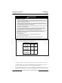
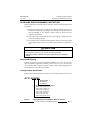
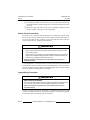
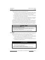
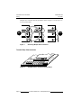
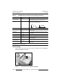
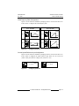
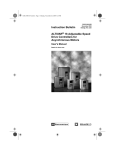
Instruction Bulletin 50006-360-01B July, 1996 Replaces 50006-360-01A dated 8/95 Price: $10.00 a 16 Adjustable Speed AC Drive Controller for Asynchronous Motors Obsolete ALTIVAR 16 Drive Controller for Asynchronous Motors 50006-360-01B May 1996 ! DANGER HAZARDOUS VOLTAGE. • Read and understand this bulletin in its entirety before installing or operating AC drive controllers. Installation, adjustment, repair and maintenance of these drive controllers must be performed by qualified personnel. • Disconnect all power before servicing drive controller. WAIT ONE MINUTE until bus capacitors discharge, then measure bus capacitor voltage between J9+ and J8- terminals to verify DC voltage is less than 45 V. See page 6. • DO NOT short across capacitors or touch unshielded components or terminal strip screw connections with voltage present. • Install all covers before applying power or starting and stopping the drive controller. • User is responsible for conforming to all applicable code requirements with respect to grounding all equipment. For more information on grounding, see page 9. • Many parts in this drive controller, including printed wiring boards, operate at line voltage. DO NOT TOUCH. Use only electrically insulated tools while making adjustments. Before installing drive controller: • Disconnect all power. • Place a “DO NOT TURN ON” label on the drive controller disconnect. • Lock disconnect in open position. Failure to observe these instructions will result in death or serious injury. Note: On earlier models, the DC bus terminals, designated J8- and J9+ in the Bus Voltage Measurement Procedure, are designated as follows: Catalog No. ATV16U09M2 ATV16U18M2 J8- J9+ J211 J212 J104 J105 J110 J112 ATV16U29M2 ATV16U18N4 ATV16U29N4 ATV16U41M2 ATV16U41N4 ATV16U54N4 ATV16U72N4 ALTIVAR is a trademark of Telemecanique S.A. or its successor-in-interest, Schneider Electric S.A. © 1993 Schneider S.A. All rights reserved. This document may not be copied in whole or in part, or transferred to any other media, without the written permission of Schneider S.A. Electrical equipment should be serviced only by qualified electrical maintenance personnel. No responsibility is assumed by Schneider S.A. for any consequences arising out of the use of this material. © 1993 Schneider S.A. All Rights Reserved 50006-360-01B July 1996 Table of Contents List of Topics RECEIVING AND PRELIMINARY INSPECTION ..........................................1 Storing and Shipping................................................................................1 Catalog Number Identification..................................................................1 TECHNICAL CHARACTERISTICS ...............................................................2 SPECIFICATIONS .........................................................................................3 DIMENSIONS................................................................................................4 INSTALLATION PRECAUTIONS ...................................................................5 MEASURING BUS CAPACITOR VOLTAGE ..................................................5 Bus Voltage Measurement Procedure......................................................6 WIRING .........................................................................................................7 General Wiring Practices..........................................................................7 Branch Circuit Connections......................................................................8 Output Wiring Precautions .......................................................................8 Grounding ................................................................................................9 Terminal Strip Characteristics ................................................................10 Wiring Diagram ......................................................................................12 DRIVE CONTROLLER SET UP ..................................................................12 Factory Settings .....................................................................................12 Switch Settings.......................................................................................14 2-WIRE TRANSITIONAL CONTROL ..........................................................16 DIRECTION OF ROTATION ........................................................................17 THERMAL OVERLOAD PROTECTION OF THE MOTOR ..........................17 AVAILABLE TORQUE..................................................................................18 PREVENTIVE MAINTENANCE...................................................................19 DIAGNOSTICS ............................................................................................20 Fault Storage ..........................................................................................20 ADDITIONAL DOCUMENTATION ...............................................................21 © 1993 Schneider S.A. All Rights Reserved Page i ALTIVAR 16 Drive Controller Table of Contents 50006-360-01B July 1996 List of Figures Figure 1 Figure 2 Figure 3 Figure 4 Figure 5 Figure 6 Figure 7 Figure 8 Figure 9 Figure 10 Figure 11 Figure 12 Figure 13 Figure 14 Figure 15 Figure 16 Figure 17 Catalog Numbers for ALTIVAR 16 Drive Controllers ................................ 1 Dimensions................................................................................................ 4 IP30 Installation......................................................................................... 5 Mounting Precautions................................................................................ 5 Measuring Bus Capacitor Voltage............................................................. 6 Wiring Terminals ....................................................................................... 7 Grounding Multiple Drive Controllers ......................................................10 ALTIVAR 16 Drive Controller Terminal Strips .........................................10 ALTIVAR 16 Drive Controller Wiring Diagram.........................................12 Drive Controller Configuration Switches..................................................14 Configuring Switch 1 ...............................................................................15 Configuring Switch 2 ...............................................................................15 2-Wire Transitional Control......................................................................16 Standard 2-Wire Control..........................................................................16 Direction of Rotation................................................................................17 Typical ALTIVAR 16 Drive Controller Torque Characteristics.................18 LED States ..............................................................................................20 List of Tables Table 1 Table 2 Table 3 Table 4 Table 5 Table 6 Page ii Technical Characteristics: ATV16•••M2: 208 V ± 10% and 240 V ± 10%, 50/60 Hz........................... 2 Technical Characteristics: ATV16•••N4: 400 V ± 15% and 460 V ± 15%, 50/60 Hz ........................... 2 Specifications ............................................................................................ 3 Terminal Strip Characteristics .................................................................11 ALTIVAR 16 Drive Controller Factory Settings .......................................12 Documentation for ALTIVAR 16 Drive Controller Products.....................21 © 1993 Schneider S.A. All Rights Reserved 50006-360-01B July 1996 ALTIVAR 16 Drive Controller Receiving and Preliminary Inspection RECEIVING AND PRELIMINARY INSPECTION Before installing the ALTIVAR 16 drive controller, read this manual and observe all precautions: ❏ Before removing the drive controller from its packing material, verify it is not damaged from shipping. Any damage to the packing carton usually indicates improper handling. If any damage is found, notify the carrier and your Square D representative. ❏ After removing the drive controller from its packaging, visually inspect the exterior for shipping damage. ❏ Verify that the drive controller nameplate and label conform to the packing slip and corresponding purchase order. Drive controller catalog numbers are explained be- low. ! CAUTION DAMAGED EQUIPMENT HAZARD. Do not operate or install any drive controller that appears damaged. Failure to follow this instruction can result in personal injury or equipment damage. Storing and Shipping If the drive controller is not being immediately installed, store it in a clean, dry area where the ambient temperature is between -25 and +70 °C (-13 to +158 °F). If the drive controller must be shipped to another location, use the original shipping material and carton to protect the drive controller. Catalog Number Identification Figure 1 shows how the ALTIVAR 16 drive controller catalog numbers are structured. A T V 1 6 U 0 9 M2 Supply voltage: M2: 208/240 V N4: 400/460 V ALTIVAR 16 Drive Controller Power: U09: 0.9 kVA; 0.37 kW; 0.5 hp U18: 1.8 kVA; 0.75 kW; 1 hp U29: 2.9 kVA; 1.5 kW; 2 hp U41: 4.1 kVA; 2.2 kW; 3 hp U54: 5.4 kVA; 3 kW; 4 hp U72: 7.2 kVA; 4 kW; 5 hp U90: x.x kVA; 5.5 kW, 7.5 hp Figure 1 Catalog Numbers for ALTIVAR 16 Drive Controllers © 1993 Schneider S.A. All Rights Reserved Page 1 ALTIVAR 16 Drive Controller Technical Characteristics 50006-360-01B July 1996 TECHNICAL CHARACTERISTICS Table 1 Drive Controller Catalog Number Technical Characteristics: ATV16•••M2: 208 V ± 10% and 240 V ± 10%, 50/60 Hz Input Line Current [1] Motor Power ATV16••••• kW hp Single Phase Three Phase 208 V 208 V 240 V Rated Transient Total Short Output Output Dissipated Circuit [2] Current Current Power @ Rating Rated Load 240 V A A A rms sym. W Maximum Fuse [3] FU1,FU2,FU3 U09M2 0.37 0.5 4.9 4.2 –– –– 2.1 3.2 22 1,000 KTK-R-6 U18M2 0.75 1 7.7 7.0 –– –– 4 5.4 35 1,000 KTK-R-10 U29M2 1.5 2 17.1 15.9 9.5 8.7 7.1 10 55 5,000 1ø: KTK-R-20 3ø: KTK-R-15 U41M2 2.2 3 24.1 21.9 13.1 11.9 10 14 65 5,000 1ø: KTK-R-30 3ø: KTK-R-20 [1] [2] [3] Values correspond to the amount absorbed by drive controllers supplied by mains with fault capacity equal to shortcircuit rating indicated in table and under nominal conditions of load and speed of the associated motor. For 60 seconds. Bussmann or equivalent. Table 2 Drive Controller Catalog Number Technical Characteristics: ATV16•••N4: 400 V ± 15% and 460 V ± 15%, 50/60 Hz Motor Power 400 V 460 V 50 Hz 60 Hz Input Line Current [1] Three Phase Rated Transient Total Output Output Dissipated [2] Current Current Power @ Rated Load Short Circuit Rating Maximum Fuse [3] ATV16••••• kW hp 400 V 460 V A A W U18N4 0.75 1 3.2 2.8 2.3 3.1 35 5,000 KTK-R-5 U29N4 1.5 2 5.7 4.9 4.1 5.5 50 5,000 KTK-R-10 U41N4 2.2 3 7.5 6.6 5.8 7.9 70 5,000 KTK-R-15 U54N4 3 –– 9.6 –– 7.8 11 100 5,000 KTK-R-20 [1] [2] [3] A rms sym. FU1,FU2,FU3 U72N4 4 5 11.3 9.9 10.5 14.2 135 5,000 KTK-R-25 U90N4 5.5 7.5 16.1 14.1 13 17.6 185 5,000 KTK-R-25 Values correspond to the amount absorbed by drive controllers supplied by mains with fault capacity equal to short-circuit rating indicated in table and under nominal conditions of load and speed of the associated motor. For 60 seconds. Bussmann or equivalent. Page 2 © 1993 Schneider S.A. All Rights Reserved 50006-360-01B July 1996 ALTIVAR 16 Drive Controller Specifications SPECIFICATIONS Table 3 Specifications Input Voltage ATV16•••M2: 208 V ± 10% and 240 V ± 10% ATV16•••N4: 400 V ± 15% and 460 V ± 15% Input Frequency 50/60 Hz ± 2 Hz Input Phases ATV16U09M2, U18M2: 1 ATV16U29M2, U41M2: 1 or 3 ATV16•••N4: 3 Output Voltage Maximum voltage equal to input voltage Output Frequency 0.1 to 50/60 Hz Output Phases 3 Transient Overtorque 150% of rated motor torque (± 5% from 5 to 50/60 Hz) Accel/Decel 3 s from 0 to 50/60 Hz (automatic ramp adaptation when transient torque capabilities are exceeded) Control Power 24 VDC +25%, -50% Speed Reference 0-10 V, 0-20 mA, 4-20 mA Run Signal 2 Inputs: FW (Forward) and RV (Reverse) Braking Automatic DC injection braking for 0.5 s if frequency drops below 0.1 Hz Display Green LED indicates drive controller supply is on Red LED indicates drive controller fault Drive Controller Protection Overvoltage and undervoltage protection Protection against input phase loss (ATV16•••N4 only) Protection against short circuits between output phases, between output phase and ground Protection against short circuits in internal control supplies (+10 V, +24 V) Overload and overtemperature protection Motor Protection Thermal I2t if motor FLA = 0.9 drive controller In (rated output current) (from 25/30 to 50/60 Hz) Temperature Operation: +32 to +104 °F (0 to +40 °C) with top plate installed +32 to +122 °F (0 to +50 °C) without top plate Storage: -13 to +158 °F (-25 to +70 °C) ATV16U90N4 ONLY: Operation: +32 to +104 °F (0 to +40 °C) +32 to +122 °F (0 to +50 °C) only with use of inductor VW3A66512 Storage: -13 to +158 °F (-25 to +70 °C) Humidity 95% maximum, non-condensing and without dripping (provide heating system if there is condensation) Altitude Up to 3,300 ft (1,000 m) without derating; derate by 3% for each additional 3,300 ft (1,000 m) Enclosure IP30 [1] Pollution Protect the drive controller against dust, corrosive gases and splashing liquid [1] Standards UL, CSA, IEC, VDE UL Listed as a Class 10 Overload Protective Device [1] Drive controller electrical creepages are designed for use in a pollution Degree 2 environment per NEMA ICS-111A and IEC 664. © 1993 Schneider S.A. All Rights Reserved Page 3 ALTIVAR 16 Drive Controller Dimensions 50006-360-01B July 1996 DIMENSIONS 4 x Ø6 G a b H c Part No. kW hp Voltage a b c ATV16U09M2 ATV16U18M2 0.37 0.75 0.5 hp 1 hp 230 V 230 V 5.90 (150) 4.72 (120) ATV16U29M2 ATV16U18N4 ATV16U29N4 1.5 0.75 1.5 2 hp 1 hp 2 hp 230 V 460 V 460 V 7.09 (180) ATV16U41M2 ATV16U41N4 ATV16U54N4 ATV16U72N4 ATV16U90N4 2.2 2.2 3 4 5.5 3 hp 3 hp 4 hp 5 hp 7.5 230 V 460 V 460 V 460 V 460 V 7.87 (200) Dimensions are in inches (millimeters). Figure 2 Page 4 Mounting Weight G H 6.30 (160) 5.39 (137) 5.91 (150) 3.97 (1.80) 4.08 (1.85) 5.67 (144) 7.87 (200) 6.61 (168) 7.48 (190) 7.28 (3.30) 7.50 (3.40) 7.50 (3.40) 5.98 (152) 9.06 (230) 7.40 (188) 8.66 (220) 9.48 (4.30) 9.70 (4.40) 9.70 (4.40) 11.02 (5.00) 11.46 (5.20) Weights are in pounds (kilograms). Dimensions © 1993 Schneider S.A. All Rights Reserved 50006-360-01B July 1996 ALTIVAR 16 Drive Controller Installation Precautions INSTALLATION PRECAUTIONS ❏ The ATV16 drive controller is IP30. When installing in an enclosure, remove the plastic plate from the top of the drive controller. ❏ Figure 3 shows the minimum clearances required around the drive controller for unobstructed airflow; D ≥ 4 in (100 mm), d ≥ 2 in (50 mm). These clearances should not be used as minimum enclosure size for proper thermal dissipation. ❏ Mount the drive controller vertically, as shown in Figure 4. Avoid placing near any heat sources. d D Figure 3 IP30 Installation Figure 4 Mounting Precautions MEASURING BUS CAPACITOR VOLTAGE DC bus capacitor voltage is measured between the J9+ and J8- terminals of the drive controller. The DC bus capacitors are discharged when input power is removed from the drive controller. To ensure the capacitors are fully discharged, always disconnect all power, wait 1 minute, then test with a DC voltmeter (1000 VDC scale) before wiring, troubleshooting or working inside the drive controller. If no reading is shown on the voltmeter, reduce scale and test again. The J9+ and J8- terminals are located on the power board, in the general area shown in Figure 5. To measure the bus capacitor voltage, follow the Bus Voltage Measurement Procedure. © 1993 Schneider S.A. All Rights Reserved Page 5 ALTIVAR 16 Drive Controller Measuring Bus Capacitor Voltage 50006-360-01B July 1996 ! DANGER HAZARDOUS VOLTAGE • Read and understand Bus Voltage Measurement Procedure before performing procedure. Measurement of bus capacitor voltage must be performed by qualified personnel. • DO NOT short across capacitors or touch unshielded components or terminal strip screw connections with voltage present. • Many parts in this drive controller, including printed wiring boards, operate at line voltage. DO NOT TOUCH. Use only electrically insulated tools. Failure to follow these instructions will result in death or serious injury. Bus Voltage Measurement Procedure 1. Disconnect all power from the drive controller. 2. Wait 1 minute to allow the DC bus to discharge. 3. Remove all covers. 4. Set the voltmeter to the 1000 VDC scale. Measure the bus capacitor voltage between the J9+ and J8- terminals to verify the DC voltage is less than 45 V. Do not short across capacitor terminals with voltage present! 5. Contact your local Square D representative if the bus capacitors are not fully discharged—do not operate the drive controller. 6. Replace all covers. ATV16U09M2, U18M2 ATV16U18N4, U29N4 J9+ J8- Figure 5 Page 6 ATV16U29M2, U41M2 ATV16U41N4, U54N4, U72N4 J8- J9+ Measuring Bus Capacitor Voltage © 1993 Schneider S.A. All Rights Reserved 50006-360-01B July 1996 ALTIVAR 16 Drive Controller Wiring WIRING Figure 6 shows the location of the drive controller wiring terminals. Press here to remove Figure 6 Wiring Terminals General Wiring Practices Good wiring practice requires the separation of control circuit wiring from all power (line) wiring. Power wiring to the motor must have the maximum possible separation from all other power wiring, whether from the same drive controller or other drive controllers; do not run in the same conduit. This separation reduces the possibility of coupling electrical transients from power circuits into control circuits or from motor power wiring into other power circuits. ! CAUTION EQUIPMENT DAMAGE HAZARD Follow wiring practices described in this document in addition to those already required by the National Electrical Code and local electrical codes. Failure to follow these instructions can result in personal injury or equipment damage. Follow the practices below when wiring ALTIVAR 16 drive controllers: ❏ Use metallic conduit for all drive controller wiring. Do not run control and power wiring in the same conduit. Note: The plastic wire entry plate is not suitable for direct conduit attachment. User must supply mechanical support and bonding means. In this case, the metal conduit Entry Plate Kit, VY1A16201 (for ATV16U09M2, U18M2), VY1A16202 (for ATV16U29M2, U18N4, U29N4) or VY1A16203 (for ATV16U41M2, U41N4, U54N4, or U72N4) can be ordered. ❏ Metallic conduits carrying power wiring or low-level control wiring must be separated by at least 3 in (7.62 cm). © 1993 Schneider S.A. All Rights Reserved Page 7 ALTIVAR 16 Drive Controller Wiring 50006-360-01B July 1996 ❏ Non-metallic conduits or cable trays used to carry power wiring must be separated from metallic conduit carrying low-level control wiring by at least 12 in (30.5 cm). ❏ Whenever power and control wiring cross, the metallic conduits and nonmetallic conduits or trays must cross at right angles. Branch Circuit Connections All branch circuit components and equipment (such as transformers, feeder cables, disconnect devices and protective devices) must be rated for the maximum input current of the ALTIVAR 16 drive controller, not the motor full load current. The drive controller input current is stamped on the nameplate. ! WARNING IMPROPERLY COORDINATED DEVICES WILL MISOPERATE • Branch circuit components and equipment must be rated for the maximum drive controller rated current. • If the system short circuit capacity (current) available at the input line terminals is larger than the nameplate rating, higher-than-rated line currents will be drawn from the input line and equipment misoperation may occur. Failure to follow these instructions can result in death, serious injury, or equipment damage. In some installations, conducted emissions to the line from the drive controller must be attenuated to prevent interference with telecommunication, radio and sensitive electronic equipment. In these instances, attenuating filters may be required. Consult factory for selection and application of these filters. Output Wiring Precautions ! WARNING DRIVE CONTROLLER DAMAGE Drive controller will be damaged if input line voltage is applied to output terminals (U/ T1, V/T2, W/T3). Check power connections before energizing drive controller. Failure to follow these instructions can result in death, serious injury, or equipment damage. The drive controller is sensitive to the amount of capacitance (either phase-to-phase or phase-to-ground) present on the output power conductors. If excessive capacitance is present, the drive controller may trip on overcurrent. Page 8 © 1993 Schneider S.A. All Rights Reserved 50006-360-01B July 1996 ALTIVAR 16 Drive Controller Wiring Follow the guidelines below when selecting output cable: ❏ Cable type: the cable selected must have a low capacitance phase-to-phase and to ground. Do not use mineral-impregnated cable because it has a very high capacitance. Immersion of cables in water increases capacitance. ❏ Cable length: the longer the cable, the greater the capacitance. Cable lengths greater than 320 ft (100 m) may cause problems. ❏ Proximity to other output cables: because of the high frequency switching and increased capacitance, the drive controller may fault under some conditions. ❏ Do not use lightning arrestors on output of drive controller. For installations where cable capacitances may be a problem, install an inductor between the drive controller and the motor. Maximum cable length in this case is 490 ft (150 m). A minimum inductance is needed to protect the drive controller output from short circuits. Provide at least 19.7 in (50 cm) of cable at drive controller output (U/T1, V/T2, W/T3). CAUTION ! DRIVE CONTROLLER SWITCH FAILURE For proper drive controller electronic short circuit protection, certain values of inductance may be required in the output power wiring. Inductance can be supplied by the power wiring or auxiliary inductors. Failure to follow these instructions can result in equipment damage. Grounding For safe, dependable operation, drive controllers must be grounded according to National Electrical Code and all local codes. To ground the drive controller: ❏ Connect a copper wire from the grounding terminal to the power system ground conductor. Wire size is determined by the drive controller size (see page 11), the National Electrical Code and local electrical codes. ❏ Verify that resistance to ground is one ohm or less. Improper grounding causes intermittent and unreliable operation. ! DANGER HAZARDOUS VOLTAGE • Ground equipment using connection provided. Drive controller panel must be properly grounded before applying power. • Do not use metallic conduits as a ground conductor. Failure to follow these instructions will result in death or serious injury. © 1993 Schneider S.A. All Rights Reserved Page 9 ALTIVAR 16 Drive Controller Wiring 50006-360-01B July 1996 Multiple drive controllers must be grounded as shown in Figure 7. Do not loop or series the ground cables. Controller Controller Controller Controller Controller Controller NO YES Controller Controller Figure 7 Controller Grounding Multiple Drive Controllers G Figure 8 Page 10 L1 L2 L3 po w er bo co COM AIV +10 AIC +24 FW RV DC Bus J8- / J9+ ar nt d ro lb oa rd Terminal Strip Characteristics U T1 V T2 W T3 + _ PA PB SA SC SB ALTIVAR 16 Drive Controller Terminal Strips © 1993 Schneider S.A. All Rights Reserved 50006-360-01B July 1996 Table 4 ALTIVAR 16 Drive Controller Wiring Terminal Strip Characteristics Terminal Reference ATV16••••• U09M2 U18M2 Function U29M2 U41M2 U••N4 Characteristics Max. Wire Size AWG (mm2) Torque lb-in (N•m) G G Ground 12 (2.5) 12 (1.4) L1 L2 L1 L2 L3 Input power 208 V ± 10% and 240 V ± 10% 400 V ± 15% and 460 V ± 15% 12 (2.5) 12 (1.4) U/T1 V/T2 W/T3 U/T1 V/T2 W/T3 Output connections to motor M2: 230 V/50 Hz 230 V/60 Hz N4: 400 V/50 Hz 460 V/60 Hz 12 (2.5) 12 (1.4) + – PA PB ATV16U09M2 ATV16U18M2 Connection for dynamic braking module ATV16U29M2 ATV16U41M2 ATV16U••N4 Connection for dynamic braking resistance See dynamic braking manual For ATV16•••M2: R ≥ 47 Ω For ATV16•••N4: R ≥ 68 Ω 12 (2.5) 12 (1.4) SA SC SB SA SC SB N.C. Contact [1] Common N.O. Contact Fault relay outputs Minimum: 10 mA, 24 VDC [2] Maximum: inductive charge of 1.5 A, 250 V 2.5 A, 30 VDC 14 (1.5) 3.5 (0.4) J9+ J8– J9+ J8– Filtered DC voltage [3] 265 V < V < 370 V 480 V < V < 745 V — — COM COM Common for speed reference inputs and control inputs 0V 14 (1.5) 3.5 (0.4) AIV AIV Speed reference voltage input 0-10 V, Impedance= 30 kΩ 14 (1.5) 3.5 (0.4) +10 +10 Reference input supply 10 VDC, 10 mA maximum 1 kΩ < R < 10 kΩ 14 (1.5) 3.5 (0.4) AIC AIC Speed reference current input 0-20 mA, 4-20 mA, Impedance = 250 Ω 14 (1.5) 3.5 (0.4) +24 +24 Control inputs supply 24 VDC (from 20 to 30 VDC) 14 (1.5) 3.5 (0.4) FW RV FW RV Forward control input Reverse control input Minimum: 10 mA, 24 VDC State 0: V < 5 V, I < 2.5 mA State 1: V > 11 V, I > 6 mA Impedance = 1.5 kΩ 14 (1.5) 3.5 (0.4) [1] [2] [3] Contact state shown with drive controller deenergized. Relay coil deenergizes on fault. Figure 8 is a general representation. Refer to the actual drive controller power board for location of J8- and J9+. Note: The reference and control inputs are isolated from the mains voltage. © 1993 Schneider S.A. All Rights Reserved Page 11 ALTIVAR 16 Drive Controller Drive Controller Set Up 50006-360-01B July 1996 Wiring Diagram G FU1 Input Power, single or 3-phase, depending on unit FU2 L1 L2 U/T1 FU3 L3 V/T2 Motor W/T3 Fault Relay, indicates when drive controller trips due to fault condition - 0-20 mA 4-20 mA 24 VDC +/PA SC -/PB Braking SB COM COM Supply SA 0-10 V R AIV +10 Control Circuit AIC ATV 16 +24 + FW FW RV RV ATV 16U••• Figure 9 ALTIVAR 16 Drive Controller Wiring Diagram DRIVE CONTROLLER SET UP Factory Settings Table 5 ALTIVAR 16 Drive Controller Factory Settings Parameter Setting Description Nominal motor voltage ATV•••M2: 230 V ATV•••N4: 400 V [1,2] Rated nameplate voltage of motor. See page 15. Nominal motor frequency 50 Hz [1,2] Output frequency selection at rated motor voltage. See page 15. Maximum frequency 50 [1,2] Maximum output frequency (Hz). See page 15. Selection of type of V/f ratio n [1,2] Selection of V/f ratio: n: Standard applications at constant torque. P: Variable torque applications (pumps, fans). L: Machines requiring high torque at low speed, machines with fast cycles, special motors. [1] [2] Modifiable with display/adjustment option. Modifiable with PC connection option. Page 12 © 1993 Schneider S.A. All Rights Reserved 50006-360-01B July 1996 Table 5 ALTIVAR 16 Drive Controller Drive Controller Set Up ALTIVAR 16 Drive Controller Factory Settings (Continued) Parameter Setting Description [2] Switching frequency 5 kHz Carrier frequency of the output pulses. Factory setting of 5 kHz can be increased to 10 kHz for less audible motor noise. When switching frequency is increased to 10 kHz, drive controller output current rating must be derated by 20%. Deceleration ramp adaptation Yes [1,2] If set to Yes and initial deceleration ramp time is too low, automatically extends deceleration ramp time, accounting for load inertia. Slip compensation Yes [1,2] If set to Yes, drive controller maintains a constant speed to the motor for a given reference as the load changes, automatically adjusting the output frequency. Automatic DC injection f < 0.1 Hz [2] DC injection braking at the end of the deceleration ramp. If enabled, will be injected when f < 0.1 Hz or when f < LSP, depending on setting. DC current level 0.7 Ith [2] Amount of DC injected at the end of the deceleration ramp. Ith = Motor thermal overload protection setting. DC current time 0.5 s [2] Length of time DC is injected at the end of the deceleration ramp. Automatic restart No [2] If set to Yes, enables drive controller to automatically restart after an overvoltage (0SF), overload (0LF) or overbraking (0BF) fault. For 0SF and 0BF faults, drive controller remains disabled for 1 minute after fault appears, causing fault relay of drive controller to engage, then restarts automatically if fault has disappeared. If fault is present at end of 1 minute, drive controller must be reset manually. Drive controller will attempt 5 automatic restarts (one every minute) before it must be manually reset. For 0LF fault, the restart is effective as soon as the thermal state drops below 100%, usually about 7 minutes after fault occurs. ! WARNING UNINTENDED EQUIPMENT ACTION • Automatic restart and catching a spinning load can only be used for machines or installations that present no danger in the event of automatic restarting, either for personnel or equipment. • Equipment operation must conform with national and local safety regulations. Failure to follow these instructions can result in serious injury or equipment damage. Catching a spinning load [1] [2] No [2] When set to Yes, allows smooth restarting of motor after a brief input line undervoltage. If the reference signal and a direction command are maintained, motor accelerates back up to speed without starting at zero. Modifiable with display/adjustment option. Modifiable with PC connection option. © 1993 Schneider S.A. All Rights Reserved Page 13 ALTIVAR 16 Drive Controller Drive Controller Set Up Table 5 50006-360-01B July 1996 ALTIVAR 16 Drive Controller Factory Settings (Continued) Parameter Setting [2] Controlled stop on loss of AC supply No Ramp type Linear [2] Description When set to Yes, at loss of input power, deceleration follows a self-adjusting ramp, which is a function of the regenerated energy. When set to No, motor coasts to a stop. Determines type of acceleration and deceleration ramps (linear or S). See diagrams below. Linear F S F Current limit 1.35 Drive Controller In Current limit value. Drive controller In = rated output current. Acceleration 3 s [1,2] Length of time to accelerate to nominal motor frequency from zero speed. Deceleration 3 s [1,2] Length of time to decelerate from nominal motor frequency to zero speed. Low speed 0 Hz [1,2] Low speed setting. High speed 50 Hz [1,2] High speed setting. See page 15. V/f ratio 20 [1,2] Adjustment of amount of motor torque supplied by the motor at low speed. Motor thermal overload protection 0.9 Drive Controller In [1,2] See page 17. Drive controller In = rated output current. Frequency loop gain 33% [1,2] Amount of frequency loop gain for maximizing motor torque. [1] [2] Modifiable with display/adjustment option. Modifiable with PC connection option. Switch Settings Figure 10 shows the location of the drive controller configuration switches. Make adjustments with power removed. Figure 10 Page 14 Drive Controller Configuration Switches © 1993 Schneider S.A. All Rights Reserved 50006-360-01B July 1996 ALTIVAR 16 Drive Controller Drive Controller Set Up Volts/Frequency Ratio Configuration Figure 11 shows selections available by changing switch 1 on front of the drive controller. Switch 1 configures the volts/frequency ratio. ATV 16•••M2 V ON ATV 16•••N4 Setting 230 50 Hz V * Factory f(Hz) 1 2 400 ON * Factory Setting 50 Hz 1 2 50 f(Hz) 50 V ON 60 Hz V 460 ON 60 Hz 230 f(Hz) 1 2 1 2 f(Hz) 60 Figure 11 60 Configuring Switch 1 Current Speed Reference Input Configuration Figure 12 shows selections available by changing switch 2 on front of the drive controller. Switch 2 configures the speed reference input. When it is set to 4-20 mA (switch 2 ON), the reference voltage (AIV) is from 2 to 10 V. * Factory ON ON Setting 0 - 20 mA 1 2 Figure 12 4 - 20 mA 1 2 Configuring Switch 2 © 1993 Schneider S.A. All Rights Reserved Page 15 ALTIVAR 16 Drive Controller Drive Controller Set Up 50006-360-01B July 1996 2-WIRE TRANSITIONAL CONTROL For drive controllers containing V2.1 IE07 or later software, setting switch 1 on the control board to 60 Hz provides “2-wire transitional” control (see Figure 13). If FW or RV is high (state 1) and a reference frequency is present when the drive controller is powered up, the drive controller will not run. FW or RV must transition from low (state 0) to high (state 1) for the drive controller to start. If switch 1 on the control board is set for 50 Hz, the drive controller provides standard 2-wire control (see Figure 14). If FW or RV is high (state 1) and a reference frequency is present when the drive controller is powered up, the drive controller will run at the commanded frequency. 1 FW 0 30 Hz Speed Ref 0 Hz 30 Hz Speed 0 Hz Figure 13 2-Wire Transitional Control 1 FW 0 30 Hz Speed Ref 0 Hz 30 Hz Speed Figure 14 0 Hz Standard 2-Wire Control Note: If standard 2-wire control and 60 Hz operation is desired, leave switch 1 in the 50 Hz position and adjust the necessary parameters with the display adjustment option or the PC connection option. Page 16 © 1993 Schneider S.A. All Rights Reserved 50006-360-01B July 1996 ALTIVAR 16 Drive Controller Direction of Rotation DIRECTION OF ROTATION Figure 15 shows how the FW and RV inputs control the rotation direction of the drive controller. Speed 1 2 Time FW RV 1 Time 1 Time FW 0 RV 0 1 When both FW and RV are selected, the forward direction has priority. 2 Direction control input selected first takes priority over the other. Figure 15 Direction of Rotation THERMAL OVERLOAD PROTECTION OF THE MOTOR Thermal overload protection to the motor is accomplished by: ❏ The I2t thermal protection of the drive controller if the nominal motor current is equal to 0.9 times the drive controller rated output current. For use in the 25/30 to 50/60 Hz frequency range. The value of the motor thermal protection can be changed with display/adjustment option. ❏ A thermal sensor integral to the motor when high torque at base speed is required. ❏ An external thermal overload relay. ! CAUTION LOSS OF MOTOR OVERLOAD PROTECTION When using external overload relays connected to the drive controller output, the overload relay must be capable of operation over the expected range of drive controller output frequencies (including direct current). When DC injection braking is used: • The overload relay must be suitable for operation with direct current flowing in the motor. • Do not use overload relays equipped with current transformers for sensing the motor current. Failure to follow these instructions can result in equipment damage. © 1993 Schneider S.A. All Rights Reserved Page 17 ALTIVAR 16 Drive Controller Available Torque 50006-360-01B July 1996 ! CAUTION MOTOR OVERHEATING This drive controller does not provide direct thermal protection for the motor. Use of a thermal sensor in the motor may be required for protection at all speeds and loading conditions. Consult motor manufacturer for thermal capability of motor when operated over desired speed range. Failure to follow these instructions can result in personal injury or equipment damage. AVAILABLE TORQUE Continuous duty: ❏ For self-ventilated motors, motor cooling depends on the speed. ❏ This results in derating for speeds less than 50% of the nameplate motor speed. For fractional powers ≤ 1/3 hp (250 W), the derating is less (e.g., 20% instead of 50% at the lowest frequency). Transient duty: ❏ The possibility of overtorque depends on the maximum amount of transient current that the drive controller is capable of delivering. Figure 16 shows the typical torque characteristics of the ALTIVAR 16 drive controller. Torque T/Tn 1.50 1.25 1 Self-ventilated motor 2 Force-ventilated motor 3 Transient overtorque 3 1 2 0.75 0.50 1 0.25 (50 Hz) 0 25 50 (60 Hz) 0 30 60 Figure 16 Page 18 Frequency (Hz) Typical ALTIVAR 16 Drive Controller Torque Characteristics © 1993 Schneider S.A. All Rights Reserved 50006-360-01B July 1996 ALTIVAR 16 Drive Controller Preventive Maintenance PREVENTIVE MAINTENANCE Read the safety statements below before proceeding with any maintenance or troubleshooting procedures. ! DANGER HAZARDOUS VOLTAGE • Read and understand this manual in its entirety before installing or operating AC drive controllers. Installation, adjustment, repair and maintenance of these drive controllers must be performed by qualified personnel. • Disconnect all power before servicing drive controller. WAIT ONE MINUTE until bus capacitors discharge, then measure bus capacitor voltage between J9+ and J8- terminals to verify DC voltage is less than 45 V. See page 6. • DO NOT short across capacitors or touch unshielded components or terminal strip screw connections with voltage present. • Install all covers and close door before applying power or starting and stopping the drive controller. • User is responsible for conforming to all applicable code requirements with respect to grounding all equipment. For more information on grounding, see page 9. • Many parts, including printed wiring boards, in this drive controller operate at line voltage. DO NOT TOUCH. Use only electrically insulated tools while making adjustments. Before servicing the drive controller: • Disconnect all power. • Place a “DO NOT TURN ON” label on the drive controller disconnect. • Lock disconnect in open position. Failure to follow these instructions will result in death or serious injury. The following preventive maintenance procedures are recommended at regular intervals: ❏ Check the condition and tightness of the connections. ❏ Make sure ventilation is effective and temperature around the drive controller remains at an acceptable level. ❏ Remove dust and debris from the drive controller, if necessary. If anything unusual occurs when putting the drive controller into service or during operation, be sure all recommendations relating to the environment, mounting and connecting the drive controller have been followed. © 1993 Schneider S.A. All Rights Reserved Page 19 ALTIVAR 16 Drive Controller Diagnostics 50006-360-01B July 1996 DIAGNOSTICS The LEDs on front of the ALTIVAR 16 drive controller indicate several states (see Figure 17). Red LED Illuminated: fault Green LED Not illuminated: no power to the drive Green LED Illuminated: drive powered, DC bus ≥ 50 V Figure 17 LED States Fault Storage When a fault occurs: ❏ The first fault detected is stored if mains voltage is maintained. ❏ The fault relay opens. To reset the fault: ❏ Remove power from the drive controller. ❏ Before switching power back on, identify and correct the cause of the fault. ❏ Restore power. This will reset the fault if it has been corrected. Note: Display/adjustment options VW3-A16101 and VW3-A16102 display the fault codes. Page 20 © 1993 Schneider S.A. All Rights Reserved 50006-360-01B July 1996 ALTIVAR 16 Drive Controller Additional Documentation ADDITIONAL DOCUMENTATION Table 6 Documentation for ALTIVAR 16 Drive Controller Products Product Catalog No. Bulletin No. ALTIVAR 16 Adjustable Speed AC Drive Controller (base product) ATV 16••••• 50006-360-01 Display/Adjustment Options: Display/Adjustment Display/Adjustment/Local Control Display/Adjustment Remote Mounting Kit VW3-A16101 VW3-A16102 VW3-A16103 50006-360-02 50006-360-02 50006-360-02 PC Connection VW3-A16104 50006-360-03 Dynamic Braking Module VW3-A16601 50006-360-08 Dynamic Braking Resistor VW3-A16705 50006-360-04 RFI Filters VW3-A16401-07 50006-360-09 Inductors (line reactors) VW3-A16501-04 50006-360-10 Option cards: General Use/Material Handling Variable Torque High Speed Motor General Use 3-Wire Control VW3-A16201 VW3-A16202 VW3-A16203 VW3-A16204 50006-360-05 50006-360-06 50006-360-07 50006-360-11 © 1993 Schneider S.A. All Rights Reserved Page 21 ALTIVAR 16 Drive Controller Additional Documentation Page 22 © 1993 Schneider S.A. All Rights Reserved 50006-360-01B July 1996 50006-360-01B May 1996 ALTIVAR 16 Drive Controller for Asynchronous Motors © 1993 Schneider S.A. All Rights Reserved 99646 50006-360-01B May 1996 Merlin Gerin Square D Telemecanique © 1993 Schneider S.A. All Rights Reserved VD0C01S301 ALTIVAR 16 Drive Controller for Asynchronous Motors