1
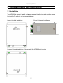
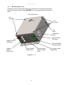
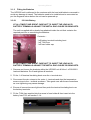
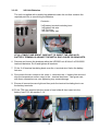
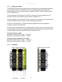
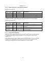
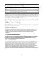
Installation & Operating Manual
iUPS200
1
Operating Manual
This page is intentionally left blank.
Warranty
For full details of the Extronics warranty policy please go to the Company section of the
website and download Terms and Conditions.
Document Number 402093 (See Last Page for Revision Details)
©2013 Extronics Limited. This document is Copyright Extronics limited.
Extronics reserve the right to change this manual and its contents without notice, the latest
version applies.
2
Operating Manual
Contents
1
2
Introduction.......................................................................................................... 4
Safety Information and Notes .............................................................................. 5
2.1
Storage of this Manual ................................................................................. 5
2.2
Special Conditions Of Safe Use ................................................................... 5
2.2.1 ATEX ...................................................................................................... 5
2.3
List Of Notes ................................................................................................ 5
3 Installation and Setting-to-Work .......................................................................... 7
3.1
Installation .................................................................................................... 7
3.1.1 Removing the cover ................................................................................ 8
3.1.2 Fitting the Batteries ................................................................................. 9
3.1.3 Fitting the Cables .................................................................................. 11
3.1.4 Terminals .............................................................................................. 11
3.1.5 Fusing – 12V System ............................................................................ 12
3.1.6 Fusing – 24V System ............................................................................ 12
3.1.7 Setting to work ...................................................................................... 12
4 Operation........................................................................................................... 13
4.1.1 Power On/Off ........................................................................................ 13
4.1.2 Status Indicators Option ........................................................................ 13
4.1.3 Logic Outputs Option ............................................................................ 13
4.1.4 Status Indicators / Logic Outputs Operation ......................................... 14
4.1.5 Output OFF Pushbutton ........................................................................ 14
5 Testing and Commissioning .............................................................................. 15
6 Intended Purpose Usage ................................................................................... 16
6.1
Transportation and Storage ........................................................................ 16
6.2
Authorized Persons .................................................................................... 16
6.3
Cleaning and Maintenance......................................................................... 16
6.3.1 Lead Acid Batteries ............................................................................... 16
6.4
Safety Precautions ..................................................................................... 17
6.5
Cleaning and Maintenance Intervals .......................................................... 17
6.5.1 Screw Thread Lubrication ..................................................................... 17
6.5.2 Surface Coating .................................................................................... 17
6.6
Aggressive substances and environments ................................................. 17
6.7
Exposure to external stresses .................................................................... 17
7 Technical Data .................................................................................................. 18
7.1
Specification ............................................................................................... 18
7.2
Enclosure Dimensions................................................................................ 19
8 Type Codes ....................................................................................................... 20
9 ATEX Label ....................................................................................................... 21
10 EC Declaration Of Conformity ........................................................................... 22
11 Manual Revision ................................................................................................ 24
3
Operating Manual
1 Introduction
The iUPS200 Zone 2 UPS Enclosure is designed to supply an uninterruptible
power supply for critical equipment located in hazardous areas.
The unit is designed to be either wall or pole mounted next to the equipment to
power.
The system includes advanced battery charge controls including built in
temperature compensation feedback to ensure the correct charging of the
internal lead acid battery.
Optional features include UPS status indication via enclosure mounted lamps,
power output disable via an enclosure mounted button, active logic outputs for
connection to a DCS or other equipment plus the option of plug and socket cable
entry instead of cable glands.
Mounting solutions and brackets are available on request.
4
Operating Manual
2 Safety Information and Notes
2.1 Storage of this Manual
Keep this user manual safe and in the vicinity of the device. All persons who have to work on
or with the device should be advised on where the manual is stored.
2.2 Special Conditions Of Safe Use
2.2.1
ATEX
There are no special conditions of safe use
2.3 List Of Notes
The notes supplied in this chapter provide information on the following.
• Danger / Warning.
o Possible hazard to life or health.
• Caution
o Possible damage to property.
• Important
o Possible damage to enclosure, device or associated equipment.
• Information
o
Notes on the optimum use of the device
Warning
Installation to be by skilled electricians and instructed personnel in
accordance with national legislation, including the relevant standards
and, where applicable, in accordance with IEC 79.17 on electrical
apparatus for explosive atmospheres.
Warning!
For the installation, maintenance and cleaning of the units, it is
absolutely necessary to observe the applicable regulations and
provisions concerned with explosion protection (EN60079-0:2006, EN
60079-14:2008) as well as the Accident Prevention Regulations.
Warning!
The iUPS200 must only be operated in ATEX Gas Zone 2 hazardous
areas, or in safe areas. Refer to the ATEX certificate for further
information.
Warning!
The iUPS200 must not be stored or operated outside of its rated
temperature range as stated on the ATEX certificate.
Warning!
The technical data indicated on the iUPS200 ATEX rating plate, this
manual and the ATEX certificate must be observed at all times.
5
Operating Manual
Warning!
The ATEX rating plate must be fitted at all times, if damaged it must be
replaced immediately or the iUPS200 must be removed from service and
the hazardous area.
Warning!
Changes in the design and modifications to the equipment are not
permitted.
Warning!
The iUPS200 shall be operated as intended and only in an undamaged
condition.
Warning!
Never operate the iUPS200 unit outside its rated voltage, current &
power as indicated in the specification or the safety of the unit may be
impaired.
Caution
This assembly may weigh up to 15Kg depending on requirements,
therefore ensure the assembly is mounted using suitable fixtures.
Important
Never exceed the maximum loading of the iUPS200 as stated in the
specifications.
Important
The iUPS200 is supplied fitted with anti-seize grease on the lid screws.
Ensure that this is not removed during installation. See section 6.5.1 for
maintenance details.
Important
The iUPS200 is supplied with a protective coating to prevent ‘tea
staining’ of the stainless steel enclosure. Take care to avoid damage to
this coating during handling and installation. Do not use abrasive
substances to clean the enclosure. See section 6.5.2 for maintenance
details.
6
Operating Manual
3 Installation and Setting-to-Work
3.1 Installation
The iUPS200 is simple to install and can be secured directly to suitable surface using
the mounting holes on the Enclosure. The iUPS200 enclosure can be installed either
horizontally or vertically but never upside down.
Correct Vertical Installation
Correct Horizontal Installation
Incorrect Vertical Installation – Never install the iUPS200 unit like this
7
Operating Manual
3.1.1
Removing the cover
Unscrew the four screws and remove the enclosure lid. If required the lid earth
connection may be removed but ENSURE it is re-connected when the lid the refitted.
Top of Enclosure
Lid
screws
Lid
screws
Vent
Valve
Certification
Label
Optional Output
Off Button
Optional Input
OK Lamp
.
Optional Battery
Charging Lamp
Optional
Battery
High Lamp
Power Supply
Cable Entry
Diagram 3.1.1
8
Optional Logic
Outputs Cable
Entry
DC Output Power
Cable Entry
Operating Manual
3.1.2
Fitting the Batteries
The iUPS200 unit is delivered to the customer with the lead acid batteries removed to
avoid any damage in transit. The batteries need to be installed and re-connected as
per the diagrams below before the unit can be powered up.
3.2.2.1
12V Unit Battery
AT ALL TIMES TAKE GREAT CARE NOT TO SHORT THE LEAD ACID
BATTERY TERMINALS AGAINST THE METAL ENCLOSURE OR BRACKETS.
The unit is supplied with a plastic bag attached inside the unit that contains the
required parts for re-connecting the batteries.
Contents :1 off battery terminal insulating boot
1 off T10A fuse
1 off fuse holder cap
AT ALL TIMES TAKE GREAT CARE NOT TO SHORT THE LEAD ACID
BATTERY TERMINALS AGAINST THE METAL ENCLOSURE OR BRACKETS.
1. Remove and loosen the brackets within the iUPS200 unit & fit the 1 off 9020001
lead acid batteries. Re-fit and tighten all brackets.
2. Fit the 1 off terminal insulating boots over the + terminal wire.
3. Re-connect the wire crimps to the outer +/- terminals and also the temperature
sensor crimp to the – terminal as shown. Take great care with these connections
as over tightening may cause damage.
4. Ensure all connections are tight and then push the terminal insulating boot over
the battery terminals.
5. Fit the T10A fuse supplied into the screw in fuse holder & then insert into the
battery fuse FS3, see section 3.1.4.
9
Operating Manual
3.2.2.2
24V Unit Batteries
The unit is supplied with a plastic bag attached inside the unit that contains the
required parts for re-connecting the batteries.
Contents :3 off battery terminal insulating boot
1 off battery link wire
1 off T5A fuse
1 off fuse holder cap
AT ALL TIMES TAKE GREAT CARE NOT TO SHORT THE LEAD ACID
BATTERY TERMINALS AGAINST THE METAL ENCLOSURE OR BRACKETS.
6. Remove and loosen the brackets within the iUPS200 unit & fit the 2 off 9020002
lead acid batteries. Re-fit and tighten all brackets.
7. Fit the 3 off terminal insulating boots over the + terminal wire & also the battery
link wire.
8. Re-connect the wire crimps to the outer +/- terminals, the +/- battery link wire and
also the temperature sensor crimp to the – terminal as shown. Take great care
with these connections as over tightening may cause damage.
9. Ensure all connections are tight and then push the terminal insulating boot over
the battery terminals.
10. Fit the T5A fuse supplied into the screw in fuse holder & then insert into the
battery fuse FS3, see section 3.1.4.
10
Operating Manual
3.1.3
Fitting the Cables
The iUPS200 unit should be powered via an external site circuit breaker/fuse/switch
to allow disconnection of the power. This circuit breaker/fuse/switch should be
located close to the unit and be suitably marked to identify it as the isolating device
for the iUPS200 unit.
The connections for AC power in and DC out will need to be terminated into the
enclosure via the correct cable entries shown in Diagram 3.1.1.
The user wiring to connect the AC power in and DC out to the unit are connected via
screw terminals and must conform to the following specification:All wires to be rated 90°C or greater operating temperature and be capable of
carrying a current of at least 10A.
All wires should be stripped and, if stranded cable is used, should be crimped using
2.5mm bootlace ferrules. The stripped/crimped wires should then be placed into the
corresponding screw terminal and securely screwed in place.
If using solid core cable;
Minimum cross section of cable = 0.2mm2
Maximum cross section of cable = 2.5mm2
If using crimped stranded core cable;
Minimum cross section of cable = 0.25mm2
Maximum cross section of cable = 1.5mm2
3.1.4
Terminals
Input / Output Terminals
F2
F1
+
-
DC Output
L
N
Battery Fuse Terminal
F3
E
AC Input
11
Operating Manual
3.1.5
Fusing – 12V System
90-264VAC, 50/60Hz input fuse, F1 = 20mm x 5, T2A
12VDC output fuse, F2 = 20mm x 5, T6.3A
Battery protection fuse, F3 = 20mm x 5, T10A
3.1.6
Fusing – 24V System
90-264VAC, 50/60Hz input fuse, F1 = 20mm x 5, T2A
24VDC output fuse, F2 = 20mm x 5, T3.15A
Battery protection fuse, F3 = 20mm x 5, T5A
Warning!
All cables should be connected to the iUPS200 via the correct
cable gland and fitted by a competent person.
Warning!
Changes in the design and modifications to the equipment are not
permitted. If any changes are performed on the enclosure the
ATEX certification will become void.
Warning!
The installer MUST ensure that that all cables have adequate
mechanical protection to avoid damage to the wires.
3.1.7
Setting to work
Once all cables are connected correctly and inspected, refit the enclosure lid using
the four screws previously removed. Use a torque screwdriver set to 2.5 Nm. Do not
over tighten screws.
Important
Ensure the lid is secure, correct cable glands are fitted and the unit device
correctly wired and earthed for the particular application before applying
power.
Important
The iUPS200 is supplied fitted with anti-seize grease on the lid screws.
Ensure that this is not removed during installation. See section 6.5.1 for
maintenance details.
Important
Ensure that the lid gasket is clean and undamaged before fitting the lid.
Take care not to trap the lid earth cable in the gasket when closing the
lid.
12
Operating Manual
4 Operation
4.1.1
Power On/Off
When AC power is applied to the unit, the 12/24V output will power on and the
various indicators or logic outputs will energise. If the AC power is removed the unit
will then go into backup mode & supply the load with 12/24V for an amount of time
dependant on load & conditions.
See section 5 for instructions on testing and commissioning the iUPS200.
4.1.2
Status Indicators Option
If the status indicator option is fitted the enclosure will have a number of indicators
and/or a pushbutton as per the diagram 4.1.2 below.
Output Off
Button
Input OK
Lamp
Battery Charging
Lamp
Battery
High Lamp
Diagram 4.1.2
4.1.3
Logic Outputs Option
If the logic output option is fitted, a multi-core cable can be installed via the optional
M20 cable gland and the connections can be made directly into the A26000x module
as per diagram 4.1.3 below. The logic outputs are active signals switched at the
output DC voltage, 12/24V.
13
Operating Manual
Diagram 4.1.3
4.1.4
Status Indicators / Logic Outputs Operation
With the AC Power ON:
Indicator /
Logic Output
Charging *
Batt High
Input OK
DC Output
Status
ON
ON
ON
ON
Battery
Condition
>0.08A / 0.05A
>11.3V / 22.6V
>13.1V / 26.2V
>10.4V / 20.9V
Description
Charging battery
Battery voltage OK (early warning)
Unit supplied by AC
Output connected to battery / PSU (active)
* Charging indicator / logic output will go OFF when batteries are fully charged.
With the AC Power OFF:
Indicator /
Logic Output
Charging
Status
Battery
Condition
Description
OFF
Batt High
OFF
<11.3V / 22.6V
Input OK
OFF
<12.8V / 25.6V
DC Output
OFF
<10.6V / 20.9V
4.1.5
No charging when AC OFF
When 15% battery energy left (early
warning)
Unit AC OFF – DC Input goes down
Load disconnected to protect battery from
deep discharging
Output OFF Pushbutton
When the unit is in back up mode (AC power OFF) the DC output can be turned off
by pressing the pushbutton as per diagram 4.1.2 or closing the contact as per
diagram 4.1.3
Note: When using this option, please keep the iUPS200 loaded. If not the iUPS200
will take 10-20 seconds for the DC output to turn off due to the internal circuits
discharging, during this time keep the pushbutton or contact closed.
14
Operating Manual
5 Testing and Commissioning
1. This manual should be fully read & the iUPS200 unit should be fully inspected
prior to powering on.
2. Check all fuses for their correct ratings; see section 3.1.5 or 3.1.6 depending on
system output voltage.
3. Connect any required test lamps, pushbutton etc, to the logic outputs if optional
pushbuttons and indicators are not fitted, see section 4.1.3.
4. Connect a suitably rated load to terminals F2(+) & - , see section 3.1.4
12V system – 2.14Ω (max 5.6A)
24V system – 9.23Ω (max 2.6A)
5. Apply 90-264VAC, 50/60Hz mains power to terminals F1, N & E , see section
3.1.4
6. Check nominally +12/24V at terminals F2(+) & -, voltage will vary dependant on
load and charging voltage.
7. Ensure battery is fully charged & then turn off the mains power supply.
8. Check +12/24V is still present at terminals F2(+) & 9. Check the lamps operate as per section 4.1.4.
10. Leave the mains power off for approx 120 minutes or until the +12/24V turns off.
11. Check the lamps operate as per section 4.1.4.
12. Re-apply the mains power to reset.
13. Check +12/24V is still present at terminals F2(+) & 14. Turn off the mains power & press the output off pushbutton to turn the unit off.
15
Operating Manual
6 Intended Purpose Usage
Important
Before setting the units to work read the technical documentation
carefully.
Important
The latest version of the technical documentation or the corresponding
technical supplements is valid in each case.
The iUPS200 is built using modern components and is extremely reliable in
operation; however it must only be used for its intended purpose. Please note that
the intended purpose also includes compliance with the instructions issued by the
manufacturer for installation, setting up and service.
Any other use is regarded as conflicting with the intended purpose. The manufacturer
is not liable for any subsequent damage resulting from such inadmissible use. The
user bears the sole risk in such cases.
6.1 Transportation and Storage
All iUPS200 devices must be so transported and stored that they are not subjected to
any excessive mechanical stresses.
6.2 Authorized Persons
Only persons trained for the purpose are authorized to handle the iUPS200; they
must be familiar with the unit and must be aware of the regulation and provisions
required for correct installation as well as the relevant accident prevention
regulations.
6.3 Cleaning and Maintenance
The iUPS200 and all its components require no maintenance and are self-monitoring.
All work on the iUPS200 by personnel who are not expressly qualified for such
activities will cause the guarantee to become void.
6.3.1
Lead Acid Batteries
The rechargeable sealed lead acid batteries contained within the iUPS200 have an
operational life of approximately 3-5 years dependant on charge/discharge cycles.
After this period it is recommended to replace them, please contact Extronics for
battery sales and advice. These batteries may be changed in the field by the
customer under safe area conditions. Please note that is essential that this work is
carried out by a competent person and care must be taken not to short the +/terminals of the batteries. Please contact Extronics for advice before performing this
work.
16
Operating Manual
6.4 Safety Precautions
Important
For the installation, maintenance and cleaning of the units, it is
absolutely necessary to observe the applicable regulations and
provisions concerned with explosion protection (EN 60079-0:2006, EN
60079-14:2008) as well as the Accident Prevention Regulations.
6.5 Cleaning and Maintenance Intervals
The cleaning intervals depend on the environment where the system is installed.
6.5.1
Screw Thread Lubrication
The threads of the lid screws and inserts have been coated with a thin layer of Rocol
251 stainless steel anti-seize grease. It is recommended that this grease should be
periodically renewed if the lid is opened frequently, to prevent the stainless threads
from binding.
Warning
6.5.2
Use only Rocol 251 or Loctite 771 as thread lubricants, as other
materials may damage the gasket and invalidate the IP rating of the
enclosure
Surface Coating
The iWAP200 enclosure has been coated with a material to prevent ‘tea staining’ of
the stainless steel by build-up of salt deposits in marine environments. Avoid damage
of the surface of the enclosure during handling.
However, if ‘tea staining’ does occur, it is purely cosmetic and does not affect the
performance of the enclosure.
If the coating is damaged, it can easily be re-applied in the field. Contact Extronics for
details.
6.6 Aggressive substances and environments
The iUPS200 is not designed to come into contact with aggressive substances or
environments, please be aware that additional protection may be required.
6.7 Exposure to external stresses
The iUPS200 is not designed to be subjected to excessive stresses e.g. vibration,
heat, impact. Additional protection is required to protect against these external
stresses.
The iUPS200 will require additional protection if it is installed in a location where it
may be subjected to damage.
17
Operating Manual
7 Technical Data
7.1 Specification
Power Supply
90-264VAC, 50/60Hz
Maximum Power Output
67.2W, 5.6A @ 12V or 62.4W, 2.6A @ 24V
depending on battery/power output voltage ordered
Backup Time
For full load, approx 120 minutes @ 25 oC
Enclosure Material
316L Stainless Steel
Ingress Protection
IP66
Weight
Approximately 15 Kg
Dimensions
390 x 290 x 161 mm (h x w x d)
Environmental
Operating temperature: –20oC to 550C
Storage temperature; –20oC to 850C
Relative humidity; 0 to 95%, non condensing
Input Connections
115/230VAC fused screw terminals via M20 cable gland
See cable gland option #6
Output Connections
Enclosure Status Indicators
(Optional, when logic outputs not
used)
12/24VDC fused screw terminals via M20 cable gland
See cable gland option #6
Battery charging, green lamp — Battery being charged
Battery high, green lamp — Battery voltage OK >11.3V / 22.6V
Input OK, green lamp — Unit supplied by AC >13.1V / 26.2V
Output off, red pushbutton — Press to turn off output voltage, remove and re-apply
mains to reset
Logic Outputs
(Optional, when status indicators
not used)
Battery charging, logic signal at battery voltage — Battery being charged
Battery high, logic signal at battery voltage — Battery voltage OK >11.3V / 22.6V
Input OK, logic signal at battery voltage — Unit supplied by AC >13.1V / 26.2V
Output off, opto isolated input — Connect to 0V to turn off output voltage, remove and
re-apply mains to reset
ATEX Certification
ITS09ATEX46416
ATEX II 3 G Ex nA II T4 (-20oC≤Ta≤+55oC)
18
7.2 Enclosure Dimensions
19
8 Type Codes
iUPS200 Zone 2 UPS Enclosure
iUPS200-[#1]-[#2]-[#3]-[#4]-[#5]-[#6]-[#7]
Specify option [#1] - Battery/Power Output Voltage
12V DC
24V DC
12
24
Specify option [#2] - Battery Charging Indicator
No Battery Charging Indicator Fitted
Enclosure Indicator Fitted
N
Y
Specify option [#3] - Battery High Indicator
No battery High Indicator Fitted
Enclosure Battery High Indicator Fitted
N
Y
Specify option [#4] - Input OK Indicator
No Input OK Indicator Fitted
Enclosure Input OK Indicator Fitted
N
Y
Specify option [#5] - Output Off Pushbutton
No Output Off Pushbutton Required
Enclosure Output Off Pushbutton Fitted
N
Y
Specify option [#6] - Enclosure Cable Entry
Cable Glands Fitted
No Cable Glands Fitted, M20 gland holes drilled
G
N
Specify option [#7] - Logic Outputs (only available when status indicators are not used,
gland not fitted if option #6N selected)
No Logic Outputs Required
Logic Outputs Fitted
N
L
20
Operating Manual
9 ATEX Label
21
Operating Manual
10 EC Declaration Of Conformity
22
Operating Manual
23
Operating Manual
11 Manual Revision
Revision
1.0
1.1
1.2
Description
Initial Release, replaces 325722_08. Added
revised d of c, updated information on
greasing threads and coating.
Fixed typo
Added warranty statement
24
Date
19/12/13
By
BTS
20/12/13
20/12/13
BTS
BTS