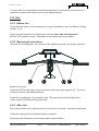
1
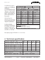
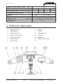
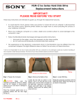
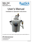
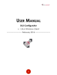
ba7047be.vp - 040216
Rev.godk:
990129 Sign.: LÖQ Kontr. HG Godk.: IH
PIAB RTM 20 D
with
microprocessor
Users Manual
Version 1.3 –
+46 8 540 839 00
1(12)
RTM 20 D - Users Manual
BA 7047be
ba7047be.vp - 040216
CONTENTS
page
1
General
2
2
Technical Specification
3
3
The RTM 20 D main parts
4
4
Function
5
5
5:1
5:2
5:3
5:4
Measuring Practice
General
Various types of ropes
Measuring on a tensed rope (check)
Slack rope to a specified tension
6
6
6
6
6
6
6:1
6:1:1
6:1:2
6:1:3
6:1:4
6:1:5
6:1:6
6:1:7
6:1:8
6:1:9
6:2
6:2:1
6:2:2
6:2:3
Handling
How to use the push-buttons
ON/OFF
ZERO
PEAK (peak value)
UNIT (alternative unit)
Low battery indication
Select “Rope No.”
Automatic turn off
Serial number and state of revision
Overload
Use
Before Use
Use - Measuring
After Use
7
7
7
7
7
7
8
8
8
8
9
10
10
10
10
7
Error Codes
11
1 General
The PIAB Rope Tension Meter RTM 20 D is an instrument specially designed for
measuring the tension in different kind of ropes. The measurements are made accurate
and swiftly somewhere on the tensed rope, whithout any extra preparations (off-loading
e.t.c.).
The measurements can be done on ropes with different diameters and different designs.
The ropes can be made of steel, metal or plastic material, and used as Guy-wires,
suspension wires, support wires for cationary systems e.t.c.
+46 8 540 839 00
2(12)
RTM 20 D - Users Manual
BA 7047be
ba7047be.vp - 040216
The RTM 20 D is able to
contain up to 10 different
calibrations.
I.e. measurements can be
done on 10 different ropes,
“Rope No”, without being
forced to use conversion
tables. On the display you
get the right tension for
these ropes.
With the Rope-List,
attached to the instrument,
you can select the correct
“Rope No” (calibration).
In order to strongly
increase the accuracity of
the readings, each rope is
calibrated at four points.
These are: 0%, 30%, 60%
och 100% of "Cal Cap"
Type
RTM 20 D
Norm.Unit
Sel.rope
S/N
XXXX
ton (metric)
Date
98-12-15
kN
Alt.Unit
= PEAK+ON/OFF Toggle + / - Confirm = ENTER/ZERO
Rope No
2
Diameter - Type
Area(mm )
Cal Cap (100%)
–1–
7.3
1x7
31,7
1.5 ton
–2–
9.2
1x7
51,7
3.0 ton
–3–
10.6
1x7
68,6
4.0 ton
–4–
13.1
1x7
102,0
5.0 ton
– 5–
15.4
1x7
143,6
5.0 ton
–6–
17.7
1x7
183,0
5.0 ton
–7–
–8–
–9–
Rope - List (example)
Max Cap = RTM’s Max. Capacity
Cal Cap = Max calibrated capacity for each rope
Max capacity range of RTM 20 D: 2, 5, 10 or 20 ton
2 Technical specification
RTM 20 D
Max. Cap.
(ton)
Resolution (guidance). Normally separatly
set for each “Rope No.”/ Cal.Cap.) (kg)
2.00
5.00
10.00
20.00
2
5
10
20
Rope dim. interval, approx. 6 – 13 (mm)
Rope dim. interval, approx. 9 – 19 (mm)
Rope dim. interval, approx. 13 – 27 (mm)
Rope dim. interval, approx. 18 – 38 (mm)
Main dimensions
RTM 20 D
(mm)
Weight RTM 20 D
(kg)
Main dimensions Transp. Case
(mm)
+46 8 540 839 00
3(12)
(LxWxH) 685x140x380
6.2
(LxWxH) 760x170x400
RTM 20 D - Users Manual
BA 7047be
ba7047be.vp - 040216
Weight (RTM + Transp. Case)
(kg)
11.2
Non-Accuracy Max ( ± % of Cal. Cap.)
3
3
3
3
Non-Accuracy Max ( ± % of Max.Cap.)
2
2
2
2
Temperature range ambient
( C)
Display
LCD
Digit size
Battery life-time
–20 C — +60 C
(mm)
(hours)
0 — 19999
12
25 (Alkaline 9V battery 6LR61)
Sealing class
IP 65
3 RTM 20 D Main parts
1
Tightening device
8
Display
2
Clamping jaw
9
Pull rod
3
Tightening screw
10
Leaf spring unit
4
Centre support ( flat)
11
Load cell
5
Outer rope support
12
Battery unit
6
Electronic unit
13
Battery unit opening
7
Push buttons
14
+46 8 540 839 00
4(12)
RTM 20 D - Users Manual
BA 7047be
ba7047be.vp - 040216
4 Function
By means of the tightening device of the centre support the rope is forced to decline according to figure 4:1. The angle will always be the same, as the rope is pressed against
the fixed centre support by means of the
clamping jaw. Even if the rope diameter is
4:1
changed, the angle will stay the same.
A resultant force is then obtained, perpendicular to the main direction of the rope, see
figure 4:2.
sin
X/2 x 1/F
X = sin x 2F
Angle
= 1.43°, gives:
sin = 0.0250 = 1/40
X = 1/40 x 2F X = 1/20 x F
4:2
i.e. ratio 20:1
The resultant force affects the pull rod which is firmly connected with the flat centre support. The pull rod affects in its turn the load cell, which gives an electrical signal which is
proportional to the force. The signal is amplified, converted and indicated on the LCD
display of the instrument.
The Load Cell
The load cell is of the type “parallelogram of flexible beam” in toughened steel. It is provided with four adhesive type strain gauges (foil gauges), where all the wires are in the
same longitudinal direction (figure 4:4).
The load cell has supports in the end points and will therefore bend when the pull rod is
loaded (figure 4:3).
4:3
+46 8 540 839 00
4:4
5(12)
RTM 20 D - Users Manual
BA 7047be
ba7047be.vp - 040216
5 Measuring Practice
5:1 General
Measurements using the RTM 20 D can be made in two different ways:
1.
The rope to be measured is loaded to the force X. The RTM is installed
and the tension value is read on the display.
2.
The RTM is installed on the rope when it is slack. Then the rope is loaded
to the force X. After that the tension value is read on the display.
Experience has given that a better measurement result is obtained when using method
1 above.
All RTM s (”Rope No.”s) are normally calibrated for measuring according to method 1,
i.e. measuring on an already tensioned rope.
5:2 Various types of ropes
On the sign at the handle of the RTM the max rope dimension (diameter) is engraved,
decided from the range of the outer rope supports. The limit for usable min rope dimension is more approximate. You can find some guidance under Technical Data chapter 2.
For multistrand (flexible) ropes you normally obtain good accuracy, even if the diameter
or/and the number of strands differ some from the calibration rope.
When it comes to measurements on rigid ropes with few strands (e.g. stay ropes)
the non-accuracy will be large if the diameter or/and the construction of the rope differ. It
is specially obvious for thick stiff ropes.
You get the best accuracy when measuring on a rope identical to the calibration rope.
5:3 Measuring on a tensed rope (check)
The instrument is normally calibrated for measuring on an already tensioned rope
according to method 1 above.
First you select correct “Rope No”, depending on which rope you are going to make
measurements on. The RTM then should be mounted/tightend to the tensed rope. The
measurement result on the display shows the tension force in the rope. It is often suitable to perform a few more measurements at different spots on the rope.
+46 8 540 839 00
6(12)
RTM 20 D - Users Manual
BA 7047be
ba7047be.vp - 040216
5:4 Slack rope to a specified tension
Select “Rope No”. Install the RTM on the slack rope. Load the rope until the RTM
shows approx. 90% of desired end value. Loosen the RTM and then install it again.
The RTM will now indicate a higher value, probably rather close to the desired end
value. If necessary, make an adjustment of the tension with the RTM installed. Loosen
the RTM and check again.
The RTM should always be completely loosened between measurements.
6 Handling
6:1 How to use the Push-buttons
ON
OFF
6:1:1 ON - OFF
Press the ON/OFF button to start the instrument. The startup is indicated on the display
by showing selected “Rope No” (earlier used rope) for about 2 seconds, e.g.
- 1-
.
The unit is turned off by pressing and holding the ON/OFF button for about 1 second.
The unit will also be automatically turned off, if any of the buttons not been activated
within a programmable time. The time can be set between 1 and 60 minutes and is done
according to item 6:1:7.
+46 8 540 839 00
7(12)
RTM 20 D - Users Manual
BA 7047be
ba7047be.vp - 040216
ENTER
ZERO
6:1:2 ZERO
When installed on the competely slack rope, the RTM should indicate zero on the display otherwise you have to zeroize the instrument. When you set to zero hold the RTM
with the tightning device hanging vertically or put the RTM in this position on a slack
rope.
The instrument is zeroed by pressing and holding the ENTER/ZERO for about 2 seconds.
000
The display will indicate
This zero-setting remains saved even if the RTM is turned off.
This zero-setting should only be done when the rope is untensioned.
6:1:3 Peak Value - highest displayed value
+
PEAK
The instrument stores automaticly the highest displayed value. This peak-value can
originate from any of the different “Rope No”s.
This peak-value remains saved even if the RTM is turned off.
To display peak-value press and hold in the PEAK - button.
When the button is released the display will indicate the present tension value.
Do not forget to reset the Peak Value before doing new measurements.
To reset the peak-value, do the following:
PEAK + ENTER/ZERO i.e.
press and hold in the PEAK button
press the ENTER/ZERO button too
release the ENTER/ZERO and PEAK buttons.
The peak value is also resetted if the instrument is set to zero.
+46 8 540 839 00
8(12)
RTM 20 D - Users Manual
BA 7047be
ba7047be.vp - 040216
6:1:4 UNIT Alternative Unit
–
UNIT
The UNIT- button is used to change between normal unit and alternative unit.
The alternative unit mode is indicated by a flashing colon : on the left side of the display.
The RTM can e.g. have normal unit in ton and alternative unit in kN.
To get the tension displayed in the altenative unit, the electronics multiply the normal
reading by a programmed factor. The factor can only be changed in the calibration
mode.
If the UNIT is held in for about 2 seconds, the display will first indicate the present
"Rope No" for 2 seconds and then the battery voltage, until the button is released. This
is indicated by that the LOBAT indicator is lit and the och prefix “b” is viewed before the
voltage, e.g. b 7.50 .
6:1:5 Low Battery Voltage
The battery voltage is continuously measured and the LOBAT-indicator will lit up when
the voltage drops below approx. 7.0V. At that point you will have a maximum of two
hours of operation left from a lithium-battery (or app. 1 hour from an alkaline battery).
If the battery voltage drops to low (app. 5.6V), an error message will be displayed for
about 4 seconds Lob
and after that the unit is turned off automatically. This ensure
correct function during measurig. Change battery.
+
PEAK
6:1:6 Select "Rope No"
ON
OFF
The RTM 20 D can have up to 10 different calibrations (10 different type of ropes)
These are stored in positions called "Rope No" - 1 -, - 2 -, .....- 9 -, - 0 -.
You have to select the right "Rope No" for your measurements, look at the line list.
If you want to use last used "Rope No" you just turn on the RTM with the ON/OFF-button.
If you want to select another "Rope No" turn on the RTM according to:
PEAK + ON/OFF.
The display will indicate last used "Rope No" e.g.
-2-
.
Use the PEAK button to increase or the UNIT button to decrease until the preferred
number is displayed.
Only the programmed and calibrated "Rope No"s will be available. The "Rope No" and
corresponding rope type are presented in the rope list attached to the instrument.
+46 8 540 839 00
9(12)
RTM 20 D - Users Manual
BA 7047be
ba7047be.vp - 040216
Accept by pressing the
ENTER/ZERO-
button (for about 2 seconds) until a colon : is lit up
on the left side of the display e.g. : - 3 "Rope No 3" has been opened.
. That is the indication of that the stored
You can cancel the selection and go back to previous rope by pressing ON/OFF.
The selected rope will remain in use even if the unit is turned off.
6:1:7 Automatic Turn OFF
–
UNIT
ON
OFF
Selection of turn off time. To save the battery the instrument will be automatically
turned off if no button is activated within a programmable time. The time can be set to
max 60 minutes and is done when you start up the RTM :
UNIT + ON/OFF
The display will first indicate SAo
and thereafter AoXX . XX is a number
between 1 and 60 (minutes).
Use the PEAK button to increase or the UNIT button to decrease until the preferred
number of minutes is displayed.
Accept by pressing the ENTER/ZERO- button (for about 2 seconds) until a colon : is lit up
on the left side of the display : AoXX . That is the indication that the time has been
stored in the permanent memory. The time will remain in use even if the unit is turned
off.
You can cancel the selection and go back to previous time by pressing ON/OFF
ENTER
6:1:8 Serial Number and state of revision
If the
ZERO
ON
OFF
button is held while you start up the RTM is started, the
2001 will be displayed for about 1.5 seconds and thereafter the
serial-number e.g.
state of revision P1.1 for about 2 seconds.
ENTER/ZERO
After that the RTM will go back to normal mode.
6:1:9 Overload
The instrument will indicate for two kinds of overload. In both cases the displayed value
will be flashing. The unit will indicate an overload by flashing the display reading in
about 1 Hz.
If the overload is due to that the "Cal Cap" of that "Rope No" has been exceeded , the
reading is on for 0.6 seconds and off for 0.4 seconds.
If the overload is due to that the "Max.Cap" (the loadcell) of RTM has been exceeded ,
the reading is on for 0.2 seconds and off for 0.8 seconds.
+46 8 540 839 00
10(12)
RTM 20 D - Users Manual
BA 7047be
ba7047be.vp - 040216
It can be difficult to immediately understand what kind of overload that is due, but it is
important to reduce the load as soon as the display flashes.
6:2 Use
6:2:1 Before Use
Check that the battery of the instrument is in good condition as per Low Battery Voltage
section 6:1:5.
Check that the threads of the tightening screw are clean and well lubricated.
ROCOL ASP grease or equal molybdenium disulphide grease is suitable.
6:2:2 Measuring Instructions
Unscrew the clamping jaw (1) by means of the tightening screw (2) enough to provide
space for the rope.
Install the RTM on the rope for good contact on the outer rope supports (3). Try not to
measure close to rope attachments etc.
Screw the clamping jaw (1) by hand to stop. The rope then should be tight to the
centre support (5) without being deformed.
6:2:3 After Use
Dirt in the threads of the tightening screw (2) must be removed. Lubricate if necessary.
Clean the instrument and check the battery condition.
Keep/carry the instrument in the transportation case provided.
+46 8 540 839 00
11(12)
RTM 20 D - Users Manual
BA 7047be
ba7047be.vp - 040216
7 Error Codes
The following error codes can be displayed at start-up or while in use. The error codes is
useful if the unit must be sent away for service maintenance.
Code
Lob
Explanation
Measure
Too low battery for reliable measurements.
Change battery.
E1
Internal error (EEPROM-memory)
Contact service.
E2
Internal error (RAM-memory)
Contact service.
+46 8 540 839 00
12(12)
RTM 20 D - Users Manual
BA 7047be