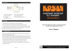
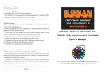
1
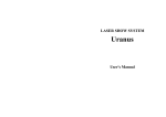
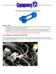
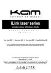
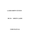
L659RGY
RGY MOVING-HEAD MULTI EFFECTS
TWINKLING LASER SHOW SYSTEM
User's Manual
Shenzhen Lanling Technology Co., Ltd
Website: www.lanlingtech.com
DMX Address Chart
General instructions
This chart lists the DMX dipswitch setting for DMX address 1 through 511. Follow the inst-
Unpacking:
ructions below to configure fixture dipswitches with you desired DMX address.
Thank you for purchasing this product. Please read user guide for safety and operations inf-
DMX Address Quick Reference Chart
DipSwitch Position
ormation before using the product. Keep this manual for future reference. This product can
create perfect laser programs and effects since it has passed a series of strictly tests before
delivery. Please check the attachments listed on the page after opening the carton. In the
event of carton damage or attachment missing in transit, please contact your dealer or our
after sales service department.
Attachments:
1. Laser Light:
1PCS
2. Power Cable:
1PCS
3. User Guide:
1PCS
Notice:
1. Do not exposure the human eye direct to laser beam.
2. Do not turn on and off the unit frequently.
3. Before using this unit make sure the power supply is ground.
4. This unit is intended for indoor use only and should be prevented form water, moisture
~ ℃, do not use this continuously
and shake. The working temperature of this unit is 18 30
over 4 hours, otherwise it shortens the lifetime of the unit.
5. Use cleaning tissue to remove the dust absorbed on the external lenses periodically to optimize light output.
6. Do not remove or break the warranty label, otherwise it void the warranty.
7. Always replace with the exact same type fuse, replacement with anything other than the
specified fuse can cause fire or electric shock and damage your unit, and will void your manufactures warranty.
DANGER
LASER RADIATION AVOID EXPOSURE
TO BEAM CLASS 3B LASER PRODUCT
DipSwitch Position
DMX Address
Page 8
Page 1
!
Technical Specification
Reference Char".
4. Turn on the all units' power, the units begins reset, then the unit begins working.
1. Voltage: AC110V or AC200V-250V/ 50HZ-60HZ/ Fuse: 2A/250V
5. Use DMX console to control your units.
2. Rated Power: 20W
Notes:
3. Laser: 50mW@532nm, green DPSS laser
1. DMX console can not be used in Master-Slave operation (Sound Active or AUTO mode ).
130mW@650nm, red Laser
2. There should be only one master unit in Master-Slave operation.
4. Working Modes: DMX, Sound Active, AUTO, Master-Slave
5. DMX Control Channel: 9 channels
Troubleshooting
6. Graphics & Effects: more than 500 green or red laser beams shootted out within
40 angles, build-in more than 50 scan track or pattern, X and Y scan angles ±30°,
1. If the power supply indicator doesn't light up and the laser doesn't work, please check the
such as a “moving head” twinkling laser star
power supply and the input voltage.
7. Interface: 3 pins XLR jack for DMX or Maser-Slave linking
2. In Stand-Alone operation, if the power supply indicator is light up and sound active indic-
8. Size: 500*350*230mm
ator isn't light up, but the laser is shut off doesn't work.
9. Weight:5.5Kg
A. Because sound is too small make for laser shut off in sound active, please increase the
music volume or increase audio sensitivity with sensitivity knob, please check as below.
B. Please check if unit has been set up in slave mode, then set up in master mode.
Features
3. In Master-Slave operation, slave unit don't function, please check as below.
A. Make sure to there's only one master in the chain, and the others are set in slave mode.
1. Various working modes
B. Make sure to control the unit without DMX console controlling.
Includes four working modes as DMX, Sound Active, AUTO and Master-Slave Control
C. Make sure to take a good quality power cable and connection.
for different applications.
4. In DMX mode operation, the laser is OFF and the DMX signal indicator is unlighted, pl-
2. DMX control
ease check as below.
The unit has 9 channels functions of scan track, XY position, XY movement speed,
A. Make sure to set up the DMX mode.
spin direction, spin speed, frequency flashing and color controlled. The unit has
B. Make sure to have a good connection.
BLACK OUT function. The uint will shut OFF if no DMX512 signal.
5. In DMX operation, the unit can’t be controlled by the DMX console, but the DMX signal
3. Master-Slave function
indicator is flashing, please make sure the DMX console and unit have the same channel.
The system allow link many units (as slave unit) together to doing synchro job without
6. If the unit is fail, please turn off the unit, then turn on again after 5 minutes.
console in sound active or AUTO mode.
4. LED indicating and shut-off function
In sound active mode, the unit's panel has LED indicating for sound active. The unit will
After trying the above solution you still have a problem, please contact your dealer or
our company for service.
shut off after 8 seconds when the music stops.
5. DPSS Laser
Use Diode-Pumped Solid State green laser, stable output and long working life.
Page 2
Page 7
Front/Rear Panel
2. Set dipswitch to select Sound Active or AUTO mode.
3. Turn on the unit power, the unit begins reset, then the unit begins working.
4. The unit will react to the low frequencies of music via the internal microphone. Adjust
2
the audio sensitivity knob on the back of the unit to make the unit more or less sensitive in
4
sound active.The panel has LED indicating for sound active.
3
1
Master-Slave Operation
This mode will allow you to link up to 32 units together without controller.
Front Panel Figure
1. Install the units in a suitable position (laying or appending).
1. Laser Aperture
2. Choose a unit to function as Master mode, set dipswitch to select Sound Active or AUTO
4. Sound Active Indicator:Blue. The LED will twinkle when a stimulated sound signal is
mode. The others must be set to Slave mode, set dipswitch to select Slave mode.
2. Sound Active Microphone
3. Power Indicator:Red
received form the MIC
3. Use standard XLR microphone cable chain your units together via the XLR connector
6
on the rear of the units. For longer cable runs we suggest a terminator at the last fixture.
2
4
4. Turn on the all units' power, the units begins reset, then the unit begins working. The
5
slave units will react the same as the master unit.
1
5. The units will react to the low frequencies of music via the internal microphone. Adjust
3
the audio sensitivity knob on the back of the master unit to make the unit more or less sensitive in sound active.The panel has LED indicating for sound active.
Rear Panel Figure
2. Cooling Fan
POWER
1:MASTER:SOUND/AUTO
POWER
POWER
5. Dipswitches: Function Setting
6. DMX Signal Indicator: Green. The LED will twinkle when DMX or Master-slave
N:SLAVE
2:SLAVE
4. Audio Sensitivity Knob
3. DMX or Linking Jack
linking signal is received
Universal DMX Operation (DMX mode)
Function & Setting
This mode allows you to use universal DMX-512 console to operate.
1. Install the units in a suitable position (laying or appending).
2. Use standard XLR microphone cable chain your units together via the XLR connector
Sound Active
on the rear of the units. For longer cable runs we suggest a terminator at the last fixture.
The change of the laser pattern is controlled by sound, that is, the rhythm of the sound
3. Assign a DMX address to each the unit using dipswitches, see the "DMX Address Quick
control the effect of the changing laser pattern. Turning the sensitivity knob in the clockwise
direction to increase the fixture’s sensitivity to sound, the knob in the counter clockwise
direction to decrease. The laser diode will automatically turn off after 8 seconds when the
POWER
DMX Signal
1:DMX MODE
POWER
2:DMX MODE
Page 6
POWER
music stops.
N:DMX MODE
Page 3
AUTO
Auto cycles the built-in programs without being controlled externally. It has no laser OFF.
DMX Control
The system only accepts the DMX512 signal of international standard to control the system
mode, the laser beam ON /OFF, running direction, running speed and twinkle speed etc.
Function Chart
DMX Control Parameter Chart
Channel
CH1
Function
Mode
Dipswitch #10 is use to set master or slave mode. Master modes have sound active and
Value
Description
Close, laser OFF
DMX or SLAVE mode by data receives. Dipswitch #9 use to is set sound active or AUTO
50~99
DMX mode
mode in master mode.
100~149
Sound active mode
DMX address calculation
150~255
AUTO mode
For DMX mode, DMX address from #1 to 9# dipswitches must be set, the address is set
from 1 to 511. Each dipswitch represents a binary value.
CH2
Scan track selection 0~255
38 tracks (255/5)
CH3
Position-X
0~255
Adjust position-X
CH4
Position-X
0~255
Adjust position-Y
CH5
Scanning speed
0~255
0 is speedy, 255 is slow
0~99
Clockwise direction Spin
100~199
Stop Spin
200~255
Counter clockwise direction Spin
CH6
Spin direction
AUTO mode. Slave modes have DMX and Slave mode. The units automatically identify
0~49
Dipswitch
#1
#2
#3
#4
#5
Value
Dipswitch
#6
#7
#8
#9
#10
1
2
4
8
16
Value
32
64
128
256
DMX, Set to "0"
CH7
Spin speed
0~255
0 is speedy, 255 is slow
One unit has 5 channels, so each unit must be assigns 5 channels at least. We may assign 8
CH8
frequency flashing 0~255
0 is speedy, 255 is slow
channels for one unit, then DMX address = 8*N + 1, N=0, 1, 2, 3 …… Example,
CH9
Color Selection
(Yellow)
0~99
Red+Green
100~199
Red
200~255
Green
When the CH1 is selected the DMX mode(DMX value is 50
One loop address=1, two loop address=9, three loop address=17, four loop address=25
Loop
~100), you can use channel
CH2, CH3 and CH9 to control laser beam, otherwise, CH2, CH3 and CH9 are invalid.
The only have eight channels, This laser light has nine channels.
Address
Binary
1
1
100000000
2
9
100100000
3
17
100010000
4
25
100110000
Dipswitches
#1(#1 switches is ON, the others are OFF)
#1+#4(#1 and #4 switches are ON)
#1+#5(#1 and #5 switches are ON)
#1+#4+#5(#1, #4, #5 switches are ON)
The dipswitches setting for DMX address see the " DMX Address Quick Reference Chart ".
Function setting
Uses dipswitches to assign a unit’s function: DMX/slave, or sound active, or AUTO mode.
For the unit is DMX mode, set the DMX address using dipswitch. Each dipswitch represents
a binary value. See the “Function chart”.
Operation
Stand-Alone Operation (Sound Active, AUTO mode)
The mode allows a single unit to react to the beat of the music in the master mode.
1. Install the units in a suitable position (laying or appending).
Page 4
Page 5