1
US 6,947,017 B1
5
6
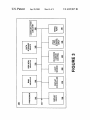
storage device 340 coupled With the bus 305 for storing
Which the user last set it. Refer to FIG. 4 for an illustration
information and instructions. Device 340 can be removable.
Portable computer system 300 also contains a display device
105 coupled to the bus 305 for displaying information to the
of the slider 430, the loW range setting 410, and the high
range setting 420.
In step 640 of FIG. 6, the processor interprets the bright
computer user.
ness setting of said slider position 430 relative to the loW
range setting 410 and the high range setting 420. For
eXample, referring to 510 of FIG. 5, the midpoint setting for
In the present embodiment, portable computer system 300
of FIG. 3 includes communication circuitry 350 coupled to
bus 305. In one embodiment, communication circuitry 350
is a universal asynchronous receiver-transmitter (UART)
module that provides the receiving and transmitting circuits
required for serial communication for the serial port 180.
Also included in computer system 300 is an optional
alphanumeric input device 106 that, in one implementation,
a brightness range of 5 nits to 65 nits is 35 nits, Where the
same midpoint setting for a brightness range of 20 nits to
10
300 nits, as shoWn on 530 of FIG. 5 is 160 nits.
Still referring to FIG. 6, the processor sends a signal to the
display controller Which, in step 650, implements the appro
priate change to the brightness level over a time period
speci?ed by stored display con?guration data so that bright
is a handWriting recognition pad (“digitizer”). Alphanumeric
input device 106 can communicate information and com 15 ness changes are not abrupt and therefore are transparent to
the user.
mand selections to main processor 310 via bus 305. In one
At any time, the user can display the currently selected
implementation, alphanumeric input device 106 is a touch
screen device. Alphanumeric input device 460 is capable of
registering a position Where a stylus element (not shoWn)
range setting and move the slider up or doWn to increase or
makes contact.
processor Will dynamically adjust the range When the ambi
decrease the brightness setting of the display. The computer
ent light changes suf?ciently, keeping the brightness level
Portable computer system 300 also includes an optional
commensurate With the slider position last selected relative
cursor control or directing device (on-screen cursor control
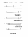
to the neW range setting. FIG. 7 illustrates user adjustments
380) coupled to bus 305 for communicating user input
to the brightness settings and computer processor adjust
information and command selections to main processor 310.
ments to the brightness range.
In one implementation, on-screen cursor control device 380
is a touch screen device incorporated With display device
105. On-screen cursor control device 380 is capable of
registering a position on display device 105 Where a stylus
element makes contact. The display device 105 utiliZed With
25
setting up to a brightness of 55 nits, as shoWn in step 720.
When the user goes into a brighter environment, the com
puter processor adjusts the range to that of 20 nits to 100
portable computer system 300 may utiliZe a re?ective,
trans?ective, transmissive or emissive type display.
In one embodiment, portable computer system 300
nits, as illustrated by step 730. The brightness setting for the
previously set slider position is noW 87 nits. The user noW
adjusts the setting doWn to a preferred level, e.g., 40 nits as
includes one or more light sensors 390 to detect the ambient
shoWn in step 740. NoW, When the user enters a darker
light and provide a signal to the main processor 310 for
determining When to implement a change in brightness
range. Display controller 370 implements display control
35
commands from the main processor 310 such as increasing
or decreasing the brightness of the display device 105.
40
set slider position is noW 20 nits.
The present invention has been described in the context of
for eXample, a housing and a processor, such that the device
performs certain functions on behalf of the processor. Fur
thermore, it is appreciated that these certain functions may
include functions other than those associated With navigat
interface. In this embodiment the user adjusts the on-screen
displayed brightness setting betWeen the loW level 410 of the
range and the high level 420 of the range by moving the
slider 430 to the right for an increase in brightness or to the
left for a decrease in brightness.
environment, the computer processor adjusts the range
doWn, as shoWn in step 750, so the setting for the previously
a portable computer system; hoWever, the present invention
may also be implemented in other types of devices having,
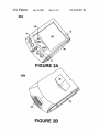
Referring noW to FIG. 4, a perspective vieW of one
embodiment of the portable computer system 400 is shown.
The display screen 105 is displaying the user brightness
setting Which may be implemented as a graphical user
In step 710 of FIG. 7, the brightness setting is at 35 nits
on a range of 5 nits to 65 nits. The user adjusts the brightness
ing, vibrating, sensing and generating audio output.
The preferred embodiment of the present invention,
45
dynamic brightness range for portable computer displays
based on ambient conditions, is thus described. While the
FIG. 5 illustrates three possible range settings and mid
point slide settings. The values are in candelas per square
present invention has been described in particular embodi
ments, it should be appreciated that the present invention
meter (cd/m2), also called nits. These user interfaces are
computer generated and displayed on the screen When the
user desires to adjust the settings. Range 510 may be used
When in a dark or dimly lit environment. Range 520 may be
used in a normal office environment and range 530 may be
used outdoors in direct sunlight. The units are measured in
should not be construed as limited by such embodiments, but
rather construed according to the beloW claims.
What is claimed is:
1. A portable computer system comprising:
nits
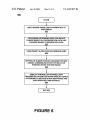
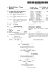
FIG. 6 is a block diagram illustrating one embodiment of
55
a processor coupled to a bus;
a light sensor coupled to said bus and for providing an
ambient light information signal to said processor;
a lighted display device coupled to said bus and for
providing a visual display;
a display controller coupled to said bus and for controlling
the present invention. In step 610 one or more light sensors
detect the ambient light and send a signal representing this
information to the processor. The signal can be from a single
sensor, or can be the average of signals from a plurality of
sensors. The processor then, as shoWn in step 620, accesses
said visual display;
stored data Which con?gures the ranges and determines if
a data storage device coupled to said bus and comprising
the ambient light signal requires a change to the brightness
precon?gured dynamically adjustable brightness range
range. If a change to brightness range is required, the
setting data for implementing a plurality of different
simultaneously stored ranges, Wherein each stored
range of said plurality of stored ranges comprises a
brightness range maXimum value and a brightness
range minimum value;
processor then implements the range change.
In step 630 of FIG. 6, according to the present embodi
ment, the slider, Which is on the user-adjustable range
display of the display device, remains in the position to
65