1
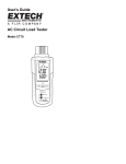
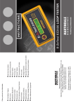
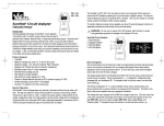
User Guide AC Circuit Load Tester For use on EPD, GFCI, and AFCI Circuits Model CT80 Introduction Thank you for selecting the Extech CT80 AC Circuit Load Tester. This device detects circuit and wiring problems such as: Poor ground impedance, false grounds, missing ground fault protection, low voltage availability under load, and high ground-to-neutral voltage. The CT80 can be used reliably on GFCI, EPD, and AFCI circuits. Circuit and wiring issues listed above can introduce shock hazards (from grounding issues) and can comprise performance of machinery and equipment (from poor ground impedance, lack of sufficient voltage under load and/or high ground-to-neutral voltage). In addition, fire can result from the heat generated by high resistance points in a circuit. Proper wiring habits have been shown to greatly increase power quality performance. This device is shipped fully tested and calibrated and, with proper use, will provide years of reliable service. Features True RMS AC measurements Voltage drop measurements on 12A, 15A, and 20A loads Voltage measurements: Line, ground-to-neutral, and peak Measures frequency of the voltage Measures Hot, Neutral, and Ground conductor impedances Performs shared Neutral test Checks 3-wire receptacle configuration Finds false grounds Tests GFCI, EPD, and AFCI circuits for proper operation 2 CT80-EN V1.1 08/12 Safety Safety Symbols This symbol, adjacent to another symbol or terminal, indicates the user must refer to the manual for further information. This symbol, adjacent to a terminal, indicates that, under normal use, hazardous voltages may be present. Double insulation Earth Ground WARNING This WARNING symbol indicates a potentially hazardous situation, which if not avoided, could result in death or serious injury. CAUTION This CAUTION symbol indicates a potentially hazardous situation, which if not avoided, may result damage to the product. Safety Information The CT80 conforms to CE and UL-1436 GFCI and AFCI testing. Exceeding the specified measurement limits of this device may compromise the device’s safety protection characteristics. Always test the CT80 on a known line voltage source to confirm proper operation before and after performing tests on other circuits. Do not use the CT80 if it appears damaged or if the operation of the unit is inconsistent with the supplied user guide instructions. Voltages above 60VDC, 42.4Vpk, and 30VAC are considered shock hazards; always observe best practice safety guidelines and precautions when working with such voltages. 3 CT80-EN V1.1 08/12 Description Meter Description 1 1. AC power cable connection 2. Test menu 3. Hot-Neutral-Ground coded measurement result 4. Primary reading display 5. Secondary reading display 6. LED test status indicators 7. GFCI test button 8. Down arrow button 9. Right arrow button 2 3 4 5 6 8 9 7 10 10. AFCI test button (Note: AC Power Cord not pictured) Display Description A V Vd % VL Z Hz G N or NEUT H mS kA, mA ASCC Peak RMS GFCI AFCI EPD OL m, M, k ‘>’ Amps or Amperes (Current) Voltage Voltage Drop Percent Voltage Drop Voltage load Impedance Hertz (cycles per second) Ohms (Resistance) Ground Neutral Hot Milliseconds kilo-amps and milli-amps Available Short Circuit Current Ground to positive peak measurement Root Mean Square Ground Fault Circuit Interrupter Arc Fault Circuit Interrupter Equipment Protection Device test Overload Unit of measure prefixes: milli, mega, and kilo ‘Greater than’ symbol Over-temperature alarm (meter operation pauses until cool-down) AFCI test in progress 4 CT80-EN V1.1 08/12 Operation Overview The CT80 AC Circuit Load Tester can test outlets or circuits under load in a matter of seconds for proper wiring, reverse polarity, and the presence of a ground. The CT80 uses a simple menu-driven display to allow the user to quickly see line voltage, voltage drop under full load, ground-to-neutral voltage, and line impedance. The GFCI and AFCI testing utility is performed separately per UL1436, disrupting the flow of electricity if a functioning GFCI or AFCI is present. Notes: To avoid the buildup of heat during load testing, allow at least 20 seconds to elapse between tests. In addition to the safety benefits, this will allow the meter to maintain its stated accuracy during repeated tests. The meter will switch off automatically if an overtemperature condition exists; the meter will automatically switch on when the temperature cools to an acceptable operational range. The CT80 is a microprocessor controlled device that prioritizes its tasks; taking a reading and analyzing the results are its top priorities. This is the reason that the keypad may not respond immediately to a key-press. The internal computer places a higher priority on completing a test than on recognizing a keystroke. To minimize this effect, press and hold a key until the display menu changes. Warning: To avoid damage to the instrument, do not use this device on the output of a UPS system, a light dimmer, or a square wave generator. Warning: Use only the supplied power/test cord with this equipment Interpreting Measurement Results Measurement Modes There are the four (4) measurement modes available. These are: 1. Voltage (V) 2. Voltage drop (Vd) 3. ASCC (Available short circuit current) 4. Impedance (Z) These measurement modes are shown on the upper left side of the display. Use the ▼ button to scroll through the mode list. Measurement results are shown on the main Wiring Configuration icon located on the upper right of meter display in conjunction with the two LED status indicators located above the down arrow button. Interpreting the measurement results is covered in the following sections. Measurement Results Coding The three circles on the wiring configuration icon in conjunction with the two rectangular LED status indicators are coded to indicate the test result such as for correct wiring, reverse polarity wiring, and ‘no ground’ condition. The wiring configuration icon and the LEDs change appearance (clear, solid, flashing) to indicate the measurement results. The test results coding and a legend for interpreting the codes are provided below. 5 CT80-EN V1.1 08/12 Illustrated Measurement Result Codes and Legend The G, N, and H circles (representing Ground, Neutral, and Hot respectively) appear on the CT80s display and can be ON, OFF, or Flashing as shown in the legend and test result codes below. The two LED status indicators (located above the down arrow button) can be ON or OFF as shown in the legend and result codes below. Legend: ON OFF FLASHING ON (LED) OFF (LED) Correct (blue display) H-N Polarity Reversed (red display) No Ground (red display) H-N Polarity Reversed and No Ground (red display) Open Hot, Open Neutral, or H - G Reversed (blank display) Note: For open HOT, open NEUTRAL, and H-G polarity reversal conditions, the meter is completely switched OFF and therefore no display or LED status is available. 6 CT80-EN V1.1 08/12 The Voltage (V) Measurement Menu The Voltage menu displays the True RMS line voltage. Use the ► button to scroll the Voltage submenu (line voltage, ground-to-neutral voltage, Peak Voltage (P), and Frequency (Hz)). The Voltage Drop (Vd) Measurement Menu The Voltage Drop (Vd) window indicates percent (%) voltage drop (with 15A load) and the Loaded Voltage (VL). The voltage drop sub-menu offers a load voltage result for 20A and 12A loads. Use the ► button to scroll the sub-menu for the 12A and 20A displays. The Impedance (Z) Measurement Menu The Impedance (Z) window indicates the impedance in ohms of the hot conductor. The impedance sub-menu displays the neutral (N) and ground (G) conductor impedances. Use the ► button to move through these sub-menu items. Note that testing ground impedance will trip a GFCI circuit. The ASCC Measurement Menu The ASCC window indicates the Available Short Circuit Current that the branch current can move through a breaker in a short circuit situation. For more specific information on the four measurement modes briefly described above, refer to the testing examples provided later in this guide. GFCI Button The GFCI (Ground Fault Circuit Interrupt) feature performs two tests: GFCI: Faults a circuit when 6 to 9mA (from hot to ground) is detected. EPD (Equipment Protective Device): For breakers equipped with an EPD, the breaker trips for ground faults greater than 30mA. To display the GFCI main menu window, press the GFCI button. To toggle the two tests use the ► button. Once the desired test is selected, press the GFCI button to start the test. These tests are further detailed in the ‘Testing Procedures’ section below. AFCI Button Depressing the AFCI button displays the AFCI main menu. Two tests can be performed from this menu: AFCI and NEUT. The AFCI tests Arc Fault Circuit Interrupting devices by creating a 106-141 amp short-duration arc between the hot and neutral conductors per UL1436. The NEUT tests for a Shared Neutral or falsely grounded neutral conductor, which causes AFCI breakers to nuisance trip with normal loads. This test applies 300mA between hot and neutral to ensure that the AFCI breaker does not trip. Refer to the testing procedures below for more detailed and application specific testing information. 7 CT80-EN V1.1 08/12 Testing Procedures Test 1: Wiring Verification The wiring configuration is the first test result that is displayed. Refer to the test result codes and legend presented earlier in the user guide. For wiring conditions other than normal, the CT80 is limited in the type of tests it can perform on a circuit until the circuit’s wiring issues are resolved. For ‘no ground’ conditions, only the line voltage and voltage drop tests can be made. For reverse polarity conditions, open neutral, or open hot conditions the meter will not display since power will not be available. Notes: The meter cannot sense two hot wires in a circuit The meter cannot simultaneously display the results of more than one circuit issue The meter cannot sense ground reversals Test 2: Voltage Measurements Warning: Do not take measurements on circuits with voltages higher than 250VAC (maximum voltage rating). Line voltage measurements should be within ±10% of the stated line voltage at 50/60Hz. For noisefree sine waves, the peak voltage should be 1.414 times the rms line voltage reading. Ground to neutral voltage should be less than 2 VAC in which case the display backlight will appear blue in color, if ground to neutral voltage is greater than 2 VAC the backlighting appears in red. Higher ground to neutral voltages indicates excessive current leakage between the neutral and ground conductors. Excessive ground to neutral voltage may result in inconsistent or intermittent equipment performance. Voltage Measurement Troubleshooting Suggestions Problems Likely Causes Out of tolerance Line Voltage (Line should be within ±10% of the stated line voltage) Overloaded circuit Possible Solutions Redistribute loads Connection within circuit or at the panel has excessive resistance Repair high resistance connection Utility company problem Contact utility company High Ground to Neutral voltage (Readings > 2VAC indicate a problem) Neutral to Ground current leakage Identify leakage, check for multiple bonding points Peak Voltage out of tolerance (For 120V Line, Peak should measure between 153 ~ 183V) Supply voltage out of tolerance Contact power utility company High peak loads on circuit Redistribute electronic devices Frequency out of tolerance (50/60Hz) Supply frequency out of tolerance Contact power utility company 8 CT80-EN V1.1 08/12 Test 3: Voltage Drop Measurements To determine voltage drop, the CT80 measures line voltage, factors in the load, measures the loaded voltage, and then calculates the voltage drop. Results for 12A, 15A, and 20A loads are provided. For nominal efficiency, a voltage drop of 5% is the maximum recommended by the National Electrical Code (NEC) board. When a voltage drop measurement of less than 5% is made, the meter’s display backlight turns blue in color. If the voltage drop is higher than 5%, the meter display appears in red. An efficient branch circuit should have less than 5% voltage drop at the furthest receptacle from the breaker panel at the termination of the cable run. A steady decrease in the voltage drop should then be measured for each receptacle tested in sequence towards the breaker panel. If the voltage drop is higher than 5% and does not noticeably decrease as the testing moves closer to the first device on the circuit, then the problem lies between the first device and the breaker panel. Visually check the terminations at the first device, the wiring between the device and the panel, and the circuit breaker connections. High resistance points can be identified as hot spots using an infrared (IR) thermometer or by measuring the voltage across the breaker. If a voltage drop measurement exceeds 5% but noticeably decreases as the testing moves closer to the panel, then the circuit may have an undersized wire, too long of a cable run, or excessive current on the circuit. Check the wires to ensure that they are sized per code and measure the current on the branch circuit. If a voltage drop reading changes significantly from one receptacle to the next, then the problem could be a high impedance point at or between two the receptacles. It is usually located at a termination point, such as a bad splice or loose wire connection, but could also be a faulty receptacle. Voltage Drop Measurement Troubleshooting Suggestions Problems Likely Causes Voltage drop > 5% Overloaded circuit Possible Solutions Redistribute loads Wrong wire gauge size for length of cable run Check code and rewire if necessary High resistance connection in the circuit or at the panel Locate bad connection and rewire or replace Test 4: ASCC Measurements The CT80 calculates the ASCC (Available Short Circuit Current) that a branch circuit can deliver through a breaker in a dead short circuit condition. The ASCC is calculated by dividing the line voltage by the circuit’s line impedance. See equation below: ASCC = Line Voltage / Hot impedance + Neutral impedance Use the ► button to simulate a situation where all three conductors (hot, neutral, and ground) are shorted together. Note that this second test will trip a GFCI. 9 CT80-EN V1.1 08/12 Test 5: Impedance (Z) Measurements The impedance measurement capability of the CT80 is used to check Hot and Neutral impedance when voltage drop measurements are too high (greater than 5%). To determine where the problem is, measure the impedances and analyze the data as follows: If one impedance measurement is exceedingly higher than the other then the problem is with the conductor that shows the higher impedance. If both impedances are high the problem could be an undersized conductor, a faulty load, or poor connections. Ground impedance should be less than 1 Ω, preferably in the 0.25 Ω region to ensure that the ground conductor can safely return current when necessary. Surge suppressors require good grounding to adequately protect against transient voltages. Note: A small amount of current is applied to the ground conductor during impedance measurements and can trip a GFCI circuit. High Impedance Troubleshooting Suggestions Problems Likely Causes Probable Solutions High hot and/or neutral impedance (Limit: 0.048Ω / ft of 14 AWG wire) Excessive loading Redistribute loads High hot and/or neutral impedance (Limit: 0.03 Ω / ft of 12 AWG wire) Undersized wiring Check code and rewire if necessary High hot and/or neutral impedance (Limit: 0.01 Ω / ft of 10 AWG wire) High resistance connection in the circuit or at the panel Locate bad connection and rewire or replace High Ground impedance (Limit: 1Ω for personal protection) Undersized wiring Check code and rewire if necessary High Ground impedance (Limit: 0.25Ω for equipment protection High resistance connection in the circuit or at the panel Locate bad connection and rewire or replace 10 CT80-EN V1.1 08/12 Test 6: GFCI (Ground Fault Circuit Interrupter) Testing A ‘GFCI’ can protect personnel from shock hazards. The CT80 tests GFCI circuits by forming a HotNeutral imbalance, leaking small amounts of current (6 to 9 mA) from Hot to Ground through a fixed resistance. A good GFCI circuit will sense this imbalance and switch off the power. The CT80 displays the current value in mA. To test a GFCI circuit: 1. Plug the meter into the receptacle under test. 2. Press the CT80 GFCI button to enter the GFCI test mode menu. 3. GFCI is the default test and the letters ‘GFCI’ should appear on the lower side of the meter’s display. If not, press the ► button once to switch to ‘GFCI’. 4. Press the GFCI button again to start the test. The current that is leaked to ground will display. The rotating display affect lets the user know that the test is in progress. 5. The GFCI circuit should typically trip within 200ms (the meter’s display will switch off because the power has been removed by the GFCI circuit). 6. When the GFCI circuit is reset, the CT80 will display the elapsed time from start of test to power down. 7. Press any button to return the meter to normal operation mode. 8. If the GFCI circuit fails to respond in 6.5 seconds, the CT80 stops the test automatically and ‘OL’ will display on the meter. Notes: 1. To test a GFCI circuit on a two wire system, a three-to-two wire adaptor must be used with the adaptor manually connected to ground (cold water pipe, for example). 2. Appliances connected to the circuit under test should be disconnected to avoid measurement errors. Test 7: EPD (Equipment Protective Device) GFCI Testing An EPD device can protect equipment as well as personnel. The CT80 tests EPD circuits by forming a Hot-Neutral imbalance, leaking current from Hot to Ground through a fixed resistance. A larger amount of current (30mA) is used than would normally be used to test a standard GFCI (6 to 9mA). A good EDP/GFCI circuit will sense this imbalance and switch off the power. The CT80 displays the current value in mA. To test an EPD/GFCI circuit: 1. Plug the meter into the receptacle under test. 2. Press the CT80 GFCI button to enter the GFCI test mode menu. 3. GFCI is the default test and the letters ‘GFCI’ will appear on the lower left side of the meter’s display. Press the ► button once to switch to ‘EPD’. 4. Now follow steps 4 through 8 in Test 6 (GFCI) above. 11 CT80-EN V1.1 08/12 Test 8: AFCI (ARC Fault Circuit Interrupter) Testing The CT80 w/AFCI applies 8 to 12 current pulses in less than a half second across hot-to-neutral with each pulse 8.3ms maximum in duration, with each pulse’s amplitude 106 to 141 amps in accordance with UL1436. A functional AFCI breaker should recognize these current pulses as a dangerous arc and disconnect the power to the circuit. To restore power, reset the breaker at the panel. To properly test the AFCI, execute the following steps: 1. Consult the AFCI manufacturer's installation instructions to determine that the AFCI is installed in accordance with the manufacturer's specifications. 2. Plug in the CT80 and check for correct wiring of receptacle and all remotely connected receptacles on the branch circuit. Then, go to the panel and operate the test button on the AFCI installed in the circuit. The AFCI must trip. If it does not, do not use the circuit - consult an electrician. If the AFCI does trip, reset the AFCI. 3. Return to the tester and press the AFCI button to enter the AFCI main menu. The AFCI symbol in the display should be highlighted as the default test. If NEUT is lit, use the right arrow button to highlight the AFCI symbol. Then, press the AFCI button, the device should trip causing the display to switch off (from the loss of power). If the AFCI fails to trip, the CT80 will not lose power and the display will show a dimly lit lightning bolt symbol. This nontrip condition would suggest: A wiring problem with an operable AFCI, or Proper wiring with a faulty AFCI. Consult with an electrician to check the condition of the wiring and AFCI. 4. CAUTION: AFCIs recognize the characteristics unique to arcing, and AFCI testers produce characteristics that mimic some forms of arcing. Because of this, the tester may give a false indication that the AFCI is not functioning properly. If this occurs, recheck the operation of the AFCI using the test and reset buttons. The AFCI’s test button function should demonstrate proper operation. Note: The AFCI circuitry is protected by a thermal sensor to assure long life. If a thermometer icon appears in the display during repeated AFCI testing, the senor delays further testing until the circuitry cools. At that point, the testing will automatically continue. Shared Neutral Test AFCI breakers are prone to nuisance tripping when wired with a shared neutral or when the neutral conductor is accidentally grounded before the panel. The AFCI tripping occurs because it senses an imbalance between the current going out on the hot and the current returning on the neutral. A shared neutral between two hot conductors creates this imbalance. The CT80 can test for these conditions by applying a small load of 300mA between hot and neutral to simulate a normal load and ensure that the AFCI breaker does not trip. To conduct a shared neutral test, press the AFCI button to enter the AFCI main menu. Press the right arrow button to highlight the NEUT symbol. Then, press the AFCI button to activate the test. The TEST icon will light brightly while the test is being conducted. The AFCI breaker should not trip. If the breaker does trip, a shared neutral is the probable cause. 12 CT80-EN V1.1 08/12 AFCI Troubleshooting Suggestions Measurement AFCI Test Shared Neutral Test Expected Result AFCI trips AFCI does not trip Problem AFCI does not trip AFCI does trip Possible Causes AFCI installed incorrectly AFCI defective High source of line impedance or resistance Shared neutral exists Possible Solutions Check wiring and rewire device according to manufacturer’s instructions Replace AFCI Check for high voltage drop Rewire circuit per AFCI manufacturer’s Instructions Maintenance WARNING: To avoid electrical shock, remove all inputs before opening the case. Cleaning and Storage Periodically wipe the case with a damp cloth and mild detergent; do not use abrasives or solvents to clean the instrument. Pack and store the meter safely when not in use. Do not allow the meter to remain connected to live circuitry when not in use. 13 CT80-EN V1.1 08/12 Specifications Measurement Specifications Range and Resolution Accuracy Line Voltage 85.0 to 250.0 VAC ± (1.0% + 0.2V) Peak Line Voltage 121.0 to 354.0 VAC ± (1.0% + 0.2V) 45.0 to 65.0 Hz ± (1.0% + 0.2Hz) 0.1 to 99.9% ± (2.5% + 0.2%) 10.0 to 250.0 VAC ± (2.5% + 0.2V) 0.0 to 10.0 VAC ± (2.5% + 0.2V) 0.00 to 3.00 Ω (Hot) ± (2.5% + 0.02Ω) >3 Ω (Neutral, Ground) Unspecified 1ms to 6.500 Seconds ± (1.0% + 2ms) GFCI Trip Current 6.0 to 9.0mA ± (1.0% + 0.2mA) EPD Trip Current 30.0 to 37.0mA ± (1.0% + 0.2mA) Frequency Voltage drop (%) Voltage (under load) Neutral to Ground Voltage Impedance GFCI Trip Time AFCI Test Current Pulses 8 to 12 pulses (106 to 141 amps each) AFCI Test Time 0.5 seconds total (each pulse 8.3ms max.) General Specifications Display Voltage display update rate Over range indication Equipment Power Rating Operating Temperature Storage Temperature Operating Humidity Storage Humidity Case construction Altitude Dimensions Weight Safety approvals General safety 128 x 64 LED with backlighting 2.5 seconds max. ‘OL’ display 100 to 250 VAC 3.9 VA, 45 to 65Hz, 18.0mA 0C to 50C (32F to 122F) 0C to 50C (32F to 122F) Max 80% Max 80% ABS UL 94V/0/5VA rated 2000m (6561.7 ft) 203 x 71 x 51 mm (8 x 2.8 x 2”) 317.5g (11.2 oz.) CE, ETL For indoor use and in accordance with the requirements for double insulation to IEC1010-1 (2001): EN61010-1 (2001) Overvoltage Category II 300V Pollution Degree 2. Copyright © 2012 Extech Instruments Corporation (a FLIR company) All rights reserved including the right of reproduction in whole or in part in any form www.extech.com ISO-9001 Certified 14 CT80-EN V1.1 08/12