1
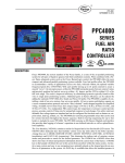
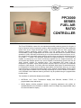
PPC-6001
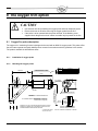
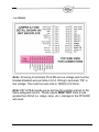
OCTOBER 7, 2015
PPC6000
SERIES
FUEL AIR
RATIO
CONTROLLER
DESCRIPTION
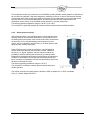
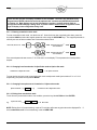
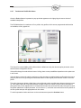
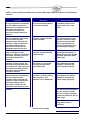
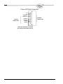
The Fireye PPC6000 is a state of the art stand-alone parallel positioning system for all types of
liquid or gaseous fuel fired combustion systems. When combined with a Fireye flame safeguard
system such as the Fireye BurnerLogix control, the PPC6000 offers the most compact and
advanced parallel positioning system available. Four fuel profiles allow the PPC6000 to
accommodate a variety of applications such as two fuels, with and without, the optional variable
speed drive (VSD). With each profile having up to 24 points entered to assure a smooth “curve”,
the microprocessor interpolates points between entered values and precisely positions fuel and
air to within +- .1 degree. This eliminates hysteresis for improved efficiency. The PPC6000 is
capable of powering up to ten 24volt servomotors supplied from the integral transformer. All
servomotors and displays operate on a secure CANbus communications protocol and can be
“daisy chained” together for simplified wiring. Two independent PID control loops for
temperature or pressure control provide precise, accurate control of firing rate for unmatched
response to load changes. Four safety rated user definable digital inputs are standard and can
be configured for functions such as lead lag, night setback, thermal shock warm up, etc. Digital
inputs can also be configured as analog inputs via the optional programmable function blocks
using Fireye Abacus software. Built in lead lag sequencing for up to four boilers is included in
every PPC6000. More elaborate lead lag schemes may be possible using the programmable
function blocks.
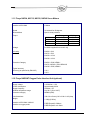
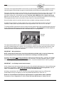
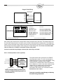
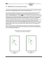
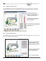
Two variations of multifunction displays are available:
NXTSD104 10.4” Color Touchscreen
programmable relays and backup.
NX610 display provides automatic storage of operating parameters and profiles for
upload/download to the PPC6000. In addition, three line voltage fully programmable relays
are mounted inside the display.
display
with
Ethernet,
Modbus
TCPIP,
4
Other options include, two Variable speed drive (VSD) outputs via daughter board, Oxygen Trim
using Fireye’s proven heated zirconia oxide probe and optional interface, a wide variety of
communications platforms such as Modbus is also available.
An optional internal freely programmable logic section of the PPC6000 means that external
PLC’s and expensive stand-alone sequencing controls may no longer be needed. Easy to
program and protect, this new feature will make the PPC6000 suitable for many unique or
unusual applications. Functions such as lead lag, sequencing, feedwater control and draft
control are just some of the ways this feature can be used.
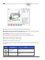
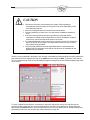
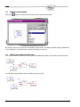
Optional ComFire software allows the user to view and control all aspects of the burner system,
provides real time trending and logging, upload and download of profiles and options. The user
can build custom screens or import actual photographs of the combustion equipment for
animation.
Summary of PPC6000 Features
State of the art surface mount technology
Smallest footprint available: 7.0” x 4.5” x 2.5”
Capable up to ten servomotors powered from the control
Two PID loops for precise process control
Simple four wire CANbus wiring reduces time and mistakes
Optional VSD card provides two VSD’s and one Analog output
Re-transmittal of most data as 420mA output (requires NXDBVSD
option)
VSD encoder feedback available
Standby lag boiler on water temp.
Built in lead/lag sequencing for up to four boilers
Fully programmable function block programming allows for custom
applications such as draft control or feedwater control
Two levels of displays: 12 Key Keypad with Backup, 10.4” Color
Touchscreen
Unparalleled worldwide support
2
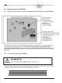
Safety information
WARNING
The equipment described in this manual is capable of causing property damage, severe injury, or
death. It is the responsibility of the owner or user to ensure that the equipment described herein is
installed, operated and commissioned in compliance with the requirements of all national and local
legislation, which may prevail.
When this equipment is fitted to an appliance due regard must also be given to the requirements of that
appliance.
Before attempting to install, commission or operate this equipment all relevant sections of this
document must be read and fully understood. If in doubt about any requirements consult Fireye.
Installation, commissioning or adjustment of this product MUST be carried out by suitably trained
engineers or personnel qualified by training and experience.
After installation or modifications to the installation all functions of the equipment MUST be checked
to ensure safe and reliable operation of the control.
The manufacturer of this equipment accepts no liability for any consequences resulting from inappropriate,
negligent or incorrect installation, commissioning or adjustment of operating parameters of the equipment.
Control panels must not be left uncovered while power is on. If it is essential to do so while rectifying faults
only personnel qualified by training and experience should be involved.
The time any covers are off must be kept to a minimum and warning notices must be posted.
Before attempting any work on this equipment or any equipment controlled by or connected to this equipment,
all related electrical supplies must be isolated.
Safety interlocks must not be removed or over-ridden. Any faults once detected must be corrected before
the control is operated.
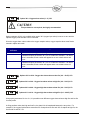
CAUTION – SOME VERSIONS OF THIS EQUIPMENT CONTAIN
A LITHIUM BATTERY IN THE DISPLAY UNIT
NOTE
The manufacturer of this equipment has a policy of continual product improvement and reserves the right to
change the specification of the equipment and the contents of this manual without notice.
3
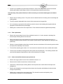
Table of contents
This manual describes the installation, commissioning, operation and maintenance of the PPC6000 series fuel
air ratio controls. It may be used in conjunction with the following other manuals:
NEX-1502 - ComFire combustion analysis tool user manual
Please read the safety information at the front of this manual before proceeding.
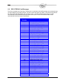
1 Technical specification
1.1 1.2 1.3 1.4 1.5 1.6 1.7 1.8 1.9 1.10 1.11 1.12 1.13 1.14 1.15 11 General
Servo-motor control – IMPORTANT: See Section 3.2
Digital outputs (PPC6000)
Alarm output (PPC6000)
Digital inputs (PPC6000)
Pressure/Temperature Input (PPC6000)
Communications interface (PPC6000)
Optional Oxygen Probe Interface Unit (NXO2INT) - optional
Optional Ambient Air Temperature Unit (NXIATS) - optional
Variable Speed Drive (VSD) Daughter Board (NXDBVSD) - optional
Fireye NXC04, NXC12, NXC20, NXC40 Servo Motors
Fireye NXO2INT Oxygen Probe Interface Unit (optional)
Fireye NXIATS Ambient Air Temperature Sensor (optional)
Approvals
Parts List with Description
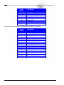
2 Installation
11 11 12 12 13 13 13 14 14 14 15 15 16 16 16 18 2.1 Mounting details for the PPC6000 control
19 2.2 Mounting details for the display module
20 2.3 Mounting details for optional Oxygen Probe Interface unit, NX02INT
21 2.4 The oxygen trim option
22 2.4.1 Oxygen Probe description
22 2.4.2 Installation of oxygen probe
22 2.4.3 Mounting the oxygen probe
23 2.4.4 Mounting arrangements for Temperature and Steam pressure sensors
24 2.4.5 Boiler temperature sensors
24 2.4.6 Steam pressure sensors
25 2.5 Option link selection (PPC6000)
26 2.5.1 General (Access to jumper’s and fuse’s is gained by removing the back cover of the PPC6000)
26 2.5.2 Line supply voltage (LK1 - 4) (PPC6000)
26 2.5.3 SENS IN and SENS SUPP (boiler temp/pressure sensor) (PPC6000)
27 2.5.4 REMOTE SETPOINT (PPC6000)
27 2.5.5 RS485 serial communications termination resistor (PPC6000)
27 2.5.6 RS485 serial communications termination resistor (daughter board)
27 IN
27 IN
27 IN
27 IN
27 2.6 Wiring
29 2.6.1 General
29 4
2.6.2 Grounding cable screens
2.6.3 GROUND (EARTH) connection
2.6.4 Ground (earth) Connection (display unit)
2.6.5 Terminal Designation
2.6.6 LINE and NEUTRAL supply (PPC6000) PE1 & PE2
2.6.7 Safety Shutdown output (PPC6000)
2.6.8 Controlled Shutdown Relay Output (PPC6000)
2.6.9 Alarm Relay output – RELAY 4 (on the PPC6000)
2.6.10 Auxiliary Relay Outputs (display)
2.6.11 Fuel Select /Profile Select Input/Purge and Ignition Prove Outputs (PPC6000)
2.6.12 Low Voltage Digital Inputs (PPC6000) – relevant Engineer’s Keys EK1-EK4 (Sec. 6.6.2)
2.6.13 Servo-motor and Display Connection (PPC6000)
2.6.14 Display Connection with PPC6000 and BurnerLogix YB110
2.6.15 Oxygen Probe Interface Connection (PPC6000)
2.6.16 Pressure/temperature sensor input (PPC6000)
2.6.17 Remote Setpoint (Analog Input 5) (PPC6000)
2.6.18 RS485 interface (PPC6000)
2.6.19 Variable Speed Drive Selection:
2.6.20 PPC6000 Variable Speed Drive Daughter Board P/N NXDBVSD
2.6.21 LIVE and NEUTRAL supply (optional Oxygen Probe Interface unit)
2.6.22 Oxygen probe connection (optional Oxygen Probe Interface unit), NX02INT
2.6.23 Inlet temperature sensor (optional)
2.7 Final checks
3 Servo-motor selection and calibration
3.1 Servo-motor selection
3.1.1 Motor requirements
3.2 IMPORTANT: Servo-motor direction warning
3.3 Locking the servo-motor to the valve shaft
3.4 Feedback potentiometer
3.5 Adjusting microswitch positions
3.6 Servomotor Replacement
4 Description of operation
32 32 33 33 35 36 36 36 37 37 38 38 39 40 40 41 41 42 43 44 44 46 47 48 48 48 49 50 50 51 52 53 4.1 The Display / Keypad
4.2 Start-up sequence
4.3 Non-volatile lockout
4.4 Modulation
4.4.1 Normal/Remote mode.
4.4.2 Local mode. (LOC 1, LOC 2)
53 54 59 59 59 59 5 Commissioning the control
60 5.1 General
5.2 Commissioning data
5.2.1 Option parameters
5.2.2 Setpoints
5.3 The Commissioning process
5.3.1 Navigation
5.4 Description of Touchscreen operation.
5.4.1 The Touchscreen
5.4.2 Touchscreen Power on.
5.4.3 The Operation Mode line and Status messages
5.4.4 Touchscreen Overview display.
5
60 61 61 61 61 61 63 63 63 63 65 5.4.5 Touchscreen Lockout Reset (Alarm Mute) Function.
5.4.6 Touchscreen LED Indication.
5.4.7 Touchscreen Fuel/Profile Select.
5.4.8 Touchscreen ‘Control’ screen.
5.4.9 Touchscreen ‘Menu’ button.
5.4.10 Touchscreen ‘Burner Settings’ button.
5.4.11 Touchscreen ‘Fault/Event Log’ button.
5.4.12 Touchscreen ‘Screen Configuration’ button.
5.4.13 Cleaning the Touchscreen
5.4.14 Touchscreen Commission mode.
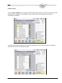
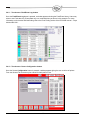
5.5 Using option set mode
5.5.1 Option parameter list
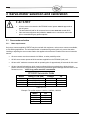
Option 00.1 - Site passcode (0 - 999) DEFAULT VALUE is 154. LV3
Option 00.2 - Serial communications control address (0 - 15) LV3
Option 00.3 - Reset hours run (0 - 1) LV3
Option 00.4 – User program select (0 / 1) LV1
Option 00.6 – Reserved
Option 00.7 – Modbus device address (1 – 99) LV3
Option 00.8 – Modbus communications speed (0 – 3) LV3
Option 01.0 – Power Up Option (0 - 30) LV3
Option 01.1 – Keyboard Auto/Manual enable (0 - 1) LV3 [Engineer’s Key 33]
Option 01.2 – Mute/Reset Input enable (0 - 2) LV3
66 66 67 68 68 68 70 70 71 72 74 74 74 74 75 75 75 75 76 76 76 76 Option 02.x – Drive Name LV3
77 Option 03.x – Drive Serial Number LV3
78 Option 04.x – Drive Usage Information LV3
78 Option 05.x – Drive Options LV3
79 Options 06.1-06.4 – Profile Naming LV3
80 Options 07.x, 08.x– RESERVED
80 Option 09.0 - Inverter control accuracy (0 / 1) LV3
80 Option 09.1 - Inverter error tolerance (0 / 1) LV3
80 Option 09.2 - Inverter closed loop gain (15 – 125%) LV3
81 Option 09.3 - Inverter stop time (0 – 100 seconds) LV3
81 Option 09.4 - Inverter acceleration time (0–100 seconds) (60 seconds max. recommended) LV381 Option 09.6 – VSD2 Speed Encoder Scaler (255 - 999) LV3
82 Option 09.7 – Reserved
82 Option 09.8 – Reserved
82 Option 14.1 – Limit Relay (0 - 8) LV3
83 Option 14.2 – Oxygen and Flue Temperature Limit Relay (0 - 8) LV3
83 Option 15.0 - Modulation sensor input type (0 - 3) LV3
Option 15.1 – Modulation input decimal places (0 to 2)
84 84 +9.99) LV3
Option 15.2 – Modulation input zero value (-999 to +999 / -99.9 to +99.9 / -9.99 to
85 +9.99) LV3
Option 15.3 – Modulation input span value (-999 to +999 / -99.9 to +99.9 / -9.99 to
85 Option 15.4 – Setpoint display units (0 – 3) LV3
Option 15.5 - Boiler high safety limit (0 - 999 / 0.0 - 99.9 / 0.00 – 9.99) LV3
Option 15.6 – Modulation Time (0 – 120 seconds) LV3
Option 15.7 – Bumpless Transfer (0 or 1) LV3
Option 15.8 – Low before Off (0 or 1) LV3
Option 15.9 - reserved
Option 16.2 – Allow profile swap (0 to 16) LV3
Option 18.1 to 18.4 – Low Voltage Fail-safe Alarm / Lockout Inputs (0 – 460) LV3
6
85 85 85 86 86 86 87 91 Option 19.1 to 19.4 – Fail-safe Alarm / Lockout Display Messages LV3
Option 20.0 – Set-point Select input (0 - 35) LV3
Option 20.1 – Boiler Shutdown input (0 - 35). LV3
Option 20.2 – Low Fire Hold input (0 - 35). LV3
Option 20.3 – Oxygen Trim Disable input (0 - 35). LV3
Option 20.4 – Ignition Wait input (0 - 35). LV3
Option 20.5 – Purge Hold input (0 - 35). LV3
Option 20.6 – Purge Time Start input (0 - 35). LV3
Option 20.7 – Analog Input 5 function (0 - 2). LV3
Option 20.8 – Digital Input - Lead Boiler Select (0 – 35) LV3
Option 21.0 – Set-point 1 enable (0 - 1) LV1
93 94 95 95 95 96 96 96 96 97 97 Option 21.1 – Set-point 1 control value (0 - 999 / 00.0 - 99.9 / 0.00 - 9.99) LV1 97 Option 21.2 – Set-point 1 proportional band (0 - 999 / 00.0 - 99.9 / 0.00 - 9.99) LV1 97 Option 21.3 – Set-point 1 integral time (0 – 999 seconds) LV1
97 Option 21.4 – Set-point 1 derivative time (0 – 999 seconds) LV1
98 Option 21.5 - Setpoint 1 control limit type (0 - 2) LV3
98 Option 21.6 - Setpoint 1 low limit control value (Cut In) (0 - 999 / 00.0 - 99.9 / 0.00 - 9.99) LV1 98 Option 21.7 - Setpoint 1 high limit control value (Cut Out) (0 - 999 / 00.0 - 99.9 / 0.00 - 9.99) LV198 Option 21.8 – Remote Setpoint 1 zero (4ma) value (0 - 999 / 00.0 - 99.9 / 0.00 - 9.99) LV1
98 Option 21.9 – Remote Setpoint 1 span (20mA) value (0 - 999 / 00.0 - 99.9 / 0.00 - 9.99) LV1
98 Option 22.0 – PID (set-point) 2 enable (0 - 1) LV1
98 Option 22.1 – Set-point 2 control value (0 - 999 / 00.0 - 99.9 / 0.00 - 9.99) LV1
99 Option 22.2 – Set-point 2 proportional band (0 - 999 / 00.0 - 99.9 / 0.00 - 9.99) LV1
99 Option 22.3 – Set-point 2 integral term (0 – 999 seconds) LV1
99 Option 22.4 – Set-point 2 derivative term (0 - 100) LV1
99 Option 22.5 - Setpoint 2 control limit type (0 - 2) LV3
99 Option 22.6 - Setpoint 2 low limit control value (0 - 999 / 00.0 - 99.9 / 0.00 - 9.99) LV1
100 Option 22.7 - Setpoint 2 high limit control value (0 - 999 / 00.0 - 99.9 / 0.00 - 9.99) LV1
100 Option 22.8 – Maximum modulation rate
100 Option 22.9 – Reserved
100 Option 23.0 – Warming Enable (0 or 1) LV1
100 Option 23.1 – Warming Limit (0 - 999 / 00.0 - 99.9 / 0.00 - 9.99) LV1
100 Option 23.2 – Warming Time (0 to 999 minutes) LV1
100 Options 24.x – Sequencing
101 Option 24.0 Sequence Slaves (number of boilers) (0-3) LV1
102 Option 24.1 -24.3 Priority Number(s) LV1
102 Option 24.4 – Lead OFF Time LV1
103 Option 24.5 – Lead (master) Boiler Select Method LV1
103 Option 24.6 – lag (slave) On Rate (0-100%) LV1
104 Option 24.7 – lag (slave) On Delay (0-999 minutes) LV1
104 Option 24.8 – lag (slave) Off Rate (0-100%) LV3
104 Option 24.9 – lag (slave) Off Delay (0-999 minutes) LV3
104 Option 25.0 – Banking based on temperature / water temperature standby for steam boiler LV3104 Option 25.1 – Water temperature zero value LV3
105 Option 25.2 – Water temperature span value LV3
105 Option 25.3 – Water temperature cut-in LV1
105 Option 25.4 – Water temperature cut-out LV1
105 Option 25.5 – Temperature based warming limit LV1
105 Option 25.6 – Lag wait time LV1
105 Option 28.0 – Analog Input decimals (0-2) LV3
105 Option 28.1 – Analog Input 1 zero (0-999) LV3
105 Option 28.2 – Analog Input 1 span (0-999) LV3
105 Option 28.3 – Analog Input 2 decimals (0-2) LV3
105 Option 28.4 – Analog Input 2 zero (0-999) LV3
105 Option 28.5 – Analog Input 2 span (0-999) LV3
105 7
Option 28.6 – Analog Input 3 decimals (0-2) LV3
Option 28.7 – Analog Input 3 zero (0-999) LV3
Option 28.8 – Analog Input 3 span (0-999) LV3
Option 29.0 – 4-20mA Output 1 function if not VSD LV3
Option 29.1 – Output1 zero value (4mA output) LV3
Option 29.2 – Output1 span value (20mA output) LV3
Option 29.3 – 4-20mA Output 2 function if not VSD LV3
Option 29.4 – Output2 zero value (4mA output) LV3
Option 29.5 – Output2 span value (20mA output) LV3
Option 29.6 – 4-20mA Output 3 function if not VSD LV3
Option 29.7 – Output3 zero value (4mA output) LV3
Option 29.8 – Output3 span value (20mA output) LV3
Option 30.0 – Oxygen probe interface serial number LV3
Option 30.1 - Oxygen probe calibration offset value (0 – 999) LV3
Option 30.2 - Oxygen probe calibration gain value (0 – 999) LV3
Option 30.4 – Flue and inlet sensor temperature units (0 – 1) LV3
Option 30.5 - Oxygen input function (0/1) LV3
Option 30.6 - Oxygen probe calibrate enable (0 – 2) LV3
Option 30.7 - Boiler transport delay (5 – 60 seconds) LV3
Option 30.8 - Reset oxygen trim profile (0/1) LV3
Option 30.9 – Automatic trim commissioning (0 / 1) LV3
Options 31.1 to 31.4 - Trim Type for profiles 1 to 4 (0 to 2) LV3
Option 32.0 - Trim limit default (0/1) LV3
Options 33.1 to 33.4 - Trim integral gain (Default 10%) LV3
Option 34.0 - Trim proportional gain (0/1) LV3
Options 34.1 to 34.4 - Trim proportional gain (0.0 – 99.9%) LV3
Option 34.5 - Calculating and entering the flow values manually LV3
Option 35.0 – Inlet temperature sensor serial number LV3
Options 35.5 to 35.8-Calorific values of fuels/profiles 1 to 4 respectively (0.0 – 99.9) LV3
Option 35.9 - Boiler radiated heat loss (0.0 – 9.9%) LV3
Option 36.0 - Flue temperature alarm select (0/1) LV3
Options 36.1 to 36.4 - Flue temperature low alarm values (0 – 999) LV3
Option 38.0 - Oxygen alarm select (0 – 2) LV3
Options 38.1 to 38.4 - Oxygen low alarm values at low fire (0.0 – 99.9%) LV3
Options 39.1 to 39.4 - Oxygen low alarm values at high fire (0.0 – 99.9%) LV3
Options 40.1 to 40.4 - Oxygen high alarm values at low fire (0.0 – 99.9%) LV3
Options 41.1 to 41.4 - Oxygen high alarm values at high fire (0.0 – 99.9%) LV3
Option 42.0 – Second Oxygen probe interface serial number LV3
Option 42.1 – Second Oxygen probe calibration offset value (0 – 999) LV3
Option 42.2 – Second Oxygen probe calibration gain value (0 – 999) LV3
Option 42.3 – Second Oxygen probe calibrate enable (0 – 2) LV3
Option 42.4 – Max oxygen variation (0 – 9.9 %) LV3
Option 42.5 – Max flue temp variation (0 to 999 ºC) LV3
Option 42.7 – Air pressure monitoring* – input number LV3
Option 42.8 – Air pressure monitoring* – Span LV3
Option 42.9 – Air pressure monitoring* – max error LV3
Option 43.0 – Water level / expansion unit** LV3 - Reserved
Option 43.1 – Water level / expansion unit** LV3 - Reserved
Option 44.0 - Set real time clock (0/1) LV1
Option 44.1 – Set Year (00 – 99) LV1
Option 44.2 – Set Month (1 – 12) LV1
Option 44.3 – Set Day of Month (1 – 31) LV1
Option 44.4 – Set Day of Week (1 - 7) LV1
Option 44.5 – Set Hours (0 - 23) LV1
Option 44.6 – Set Minutes (0 - 59) LV1
Option 44.7 – Set Seconds (0 - 59) LV1
8
105 106 106 106 106 106 107 107 107 107 107 107 109 109 110 110 110 110 111 111 111 113 114 114 115 115 115 118 118 119 119 119 120 120 120 120 120 121 121 121 122 122 123 123 123 123 123 123 123 123 123 123 124 124 124 124 Option 44.9 – Reset Fault Log (0 - 1) LV3
Option 45.0 - Erase / Restore enable (0 - 1) LV3
Option 45.1 - Erase command (0 - 5) LV3
Option 45.2 - Restore command (0 - 999) LV3
5.6 Commission ratio mode
5.6.1 Description
5.6.2 Using commission ratio mode
5.6.3 Leaving commission ratio mode
5.7 Adjust ratio mode
5.7.1 Description
5.7.2 Entering adjust ratio mode
5.7.3 Using adjust ratio mode
5.7.4 Leaving adjust ratio mode
5.8 Interrogating the software issue
124 124 125 125 126 126 126 128 128 128 128 129 130 130 6 Faults and fault finding
131 6.1 The fault display
6.2 What to do when a fault occurs
6.3 Non-volatile lockout
6.4 Fault subsets
6.5 Fault listing
6.6 The engineer's key
6.6.1 Fault history
6.6.2 Engineer’s key parameter list
6.7 Troubleshooting
6.7.1 Display / General
6.7.2 Startup
6.7.3 Commissioning
6.7.4 Modulation
6.7.5 Inverters
6.8 YB110/TSD104 Fault Messages
131 131 132 132 132 139 140 140 150 150 151 151 152 153 155 7 Inverter (variable speed) drives
7.1 7.2 7.3 7.4 157 System configuration
Description of control method
Setting up the inverter for use with the PPC6000 series
Setting up the PPC6000 series for use with a inverter drive
8 The oxygen trim option
157 158 158 159 160 8.1 Oxygen Pro probe description
8.1.1 Installation of oxygen probe
8.1.2 Mounting the oxygen probe
160 160 160 9 Appendix
163 9.1 Calibrating and servicing the oxygen probe
9.1.1 Probe calibration
9.1.2 Oxygen Probe Filter Testing
9.1.3 Removing the oxygen probe from the flue
9.1.4 Filter replacement
9.1.5 Probe mounted flue thermocouple replacement.
9.2 Troubleshooting inverter problems
9.3 PID Tutorial
9
163 163 164 164 165 165 167 168 9.4 Combustion Profile Setup Guideline
9.5 Fireye PPC6000 Efficiency Calculations
9.6 Typical Wiring Diagrams
9.7 Operator’s Guide
9.7.1 Introduction
9.7.2 General
9.7.3 Password
9.7.4 Adjusting Cut IN and Cut OUT
9.7.5 Manual Modulation
9.7.6 Resetting the Control
9.7.7 Fault and Fault Finding
9.7.8 Fault subsets
9.7.9 Fault listing
9.7.10 PID Tutorial
9.7.11 The startup / shutdown stages are as follows:
9.7.12 Non-volatile lockout
9.8 Fireye Nexus Combustion Curve
169 170 172 179 179 179 179 180 181 181 182 182 183 183 184 187 188 10 Function Block Programming Details
189 Introduction to Fireye’s Abacus Programming Software
1.1. Introduction
1.4. The schematic toolbar
1.5. Place Function blocks
1.6. Moving and editing the link lines
189 189 193 194 194 11 Circuit board connections
11.1 11.2 11.3 11.4 196 Inlet Air Temperature Sensor (Optional)
PPC6000 Variable Speed Drive Daughter Board P/N NXDBVSD
Oxygen probe connection (optional Oxygen Probe Interface unit)
PPC6000
10
196 197 198 199 1 Technical specification
1.1
General
Supply voltage
Power consumption
Supply frequency
Ambient temperature range
120/230Vac +10% - 15%
Approx. 60VA
50/60 Hz 5%
0 to 60C (32 to 140F)
Control unit protection category
IP20. The control must be situated in a clean environment
according to EN6730-1.
Indoor: Control must be mounted in an NEMA1 (IP40) enclosure
Outdoor: Control must be mounted in an NEMA3 (IP54) enclosure
Unit dimensions
Control unit 176 x 115 x 92mm (6.93 x 4.53 x 3.62 in) deep
Display 132 x132 x 36mm (5.20 x 5.20 x 1.42 in) deep
Control unit 1.55kg (3.42 lbs)
Display 0.90Kg (1.98 lbs)
Weight
Type of display
1.2
2 lines x 20 characters, vacuum fluorescent display with membrane
keypad.
Servo-motor control – IMPORTANT: See Section 3.2
Type
CANbus
Maximum (total) number of servo-motors
Maximum number of fuel profiles
Max. number of setpoints per profile
Positioning accuracy
Response time to positioning error
10 (see section 3 regarding servo-motors)
4
24 including close, purge and ignition
+/-0.1
15s for 1.0, 1s for 5.0
Number of fuel motors
Not Limited by profile (e.g. 2 or 3 fuel motors). All
non-monotonic.
Not Limited by profile (e.g. 2 or 3 fuel motors). All
non-monotonic.
Number of air (non fuel) motors
NOTE: Number of servomotors is limited in all
profiles by VA rating. See Section 3.1
11
Interface to PPC6000
CANbus
Speed
30 seconds for 90 degrees.
Microswitches
Open & close positions
Torque
Driving
4Nm/ 3 ft/lb
12Nm/ 9 ft/lb
20Nm/ 14.7 ft/lb
40Nm/ 29 ft/lb
NXC04
NXC12
NXC20
NXC40
Voltage:
24-30Vac supplied from control only
VA rating
NXC04 = 3VA
NXC12 = 5VA
NXC20 = 10VA
NXC40 = 18VA
Protection Category
NXC04 = IP40, NEMA 1
NXC12, NXC20 = IP54, NEMA 3S
NXC40 = IP65, NEMA 4
Typical accuracy
Accuracy (as specified by EN12067)
1.3
Holding
2Nm
18Nm
18Nm
20Nm
+/-0.1
+/-0.5
Digital outputs (PPC6000)
Controlled Shutdown, Safety Shutdown
Type
Minimum current
Maximum current (per output)
Maximum voltage
1.4
On-off relay, de-energize for off.
200mA rms
8A rms
250Vac rms
Alarm output (PPC6000)
Alarm
Type
Minimum current
Maximum current (per output)
Maximum voltage
On-off relay, de-energize for off.
200mA rms
4A rms
250Vac rms
12
1.5
Digital inputs (PPC6000)
Low Voltage digital inputs 1 to 4, HIGH
input, AUTO input.
Digital, Switching 0V to 5V pulsed. Feed must be taken from
the correct terminal as indicted in this manual. Inputs 1-4
configurable for 4-20Ma. Via function block programming.
Less than 25mA
10V absolute maximum
Profile Select High voltage inputs
1.6
Digital, 0V for off, 90-264Vac for on.
Pressure/Temperature Input (PPC6000)
0-5V
Maximum current
Maximum voltage
Input accuracy (typical)
Input accuracy (as specified by EN12067)
Less than 2mA
0 to 5.0 volts maximum.
0.1%
0.3%
4-20mA
2 wire loop or ext. powered
Maximum current
Burden (load) resistor
Input accuracy (typical)
Input accuracy (as specified by EN12067)
0 to 25mA maximum
220 Ohm nominal
1.0%
1.1%
1.7
Communications interface (PPC6000)
2-wire RS485 plus ground, with termination resistor selected using a link. See Section 2.5.5.
An isolated 2-wire RS485 interface is available as an option. See Section 2.5.6.
See MOD-6101 (FIREYE serial communications protocol manual) for details.
13
1.8
Optional Oxygen Probe Interface Unit (NXO2INT) - optional
Supply voltage
Power consumption
Supply frequency
Ambient temperature range
Protection category
115/230Vac 15%
Approximately 60VA
50/60Hz 5%
0 to 60C (32 to 140F)
NEMA4 (IP65).
Unit dimensions
Weight
160 x 98 x 63mm (6.30 x 3.86 x 2.48“) deep
1.34Kg (2.95 lbs)
Interface to PPC6000 series.
Interface to oxygen probe.
FIREYE specific CANbus.
FIREYE specific or 4-20mA
1.9
Optional Ambient Air Temperature Unit (NXIATS) - optional
Type
Ambient temperature range
Protection category
CANbus
0 to 60C (32 to 140F)
NEMA3 (IP54)
Unit dimensions
Weight
57 x 63 x 35 mm (2.25 x 2.5 x 1.37 inches)
0.15 kg (5.4 oz.)
Interface to PPC6000 series.
FIREYE specific CANbus.
1.10 Variable Speed Drive (VSD) Daughter Board (NXDBVSD) - optional
Ambient temperature range
Protection category
0 to 60C (32 to 140F)
Not applicable (fits inside PPC6000 unit).
Analog inputs (4 – 20mA)
Input impedance
3 max (non-isolated)
120ohms
Analog outputs (4 – 20mA)
Maximum loop resistance
Isolation voltage
3 max (isolated)
250 ohms
50v
RS485 communications.
Modbus RTU
14
1.11 Fireye NXC04, NXC12, NXC20, NXC40 Servo Motors
Interface to PPC6000
CANbus
Speed
30 seconds for 90 degrees.
Microswitches
Open & close positions
Torque
NXC04
NXC12
NXC20
NXC40
Driving
4Nm/ 3 ft/lb
12Nm/ 9 ft/lb
20Nm/ 14.7 ft/lb
40Nm/ 29 ft/lb
Voltage:
24-30Vac supplied from control only
VA rating
NXC04 = 3VA
NXC12 = 5VA
NXC20 = 10VA
NXC40 = 18VA
Protection Category
NXC04 = IP40, NEMA 1
NXC12, NXC20 = IP54, NEMA 3S
NXC40 = IP65, NEMA 4
Typical accuracy
Accuracy (as specified by EN12067)
Holding
2Nm
18Nm
18Nm
20Nm
+/-0.1
+/-0.5
1.12 Fireye NXO2INT Oxygen Probe Interface Unit (optional)
Supply voltage
Power consumption
Supply frequency
Ambient temperature range
Protection category
115/230Vac 15%
Approximately 60VA
50/60Hz 5%
0 to 60C (32 to 140F)
NEMA4 (IP65).
Unit dimensions
Weight
160 x 98 x 63mm (6.30 x 3.86 x 2.48“) deep
1.34Kg (2.95 lbs)
Interface to PPC6000 / NX6100
Interface to oxygen probe.
FIREYE specific CANbus.
FIREYE specific or 4-20mA
15
1.13 Fireye NXIATS Ambient Air Temperature Sensor (optional)
Type
Ambient temperature range
CANbus
-29C to 60C (-20F to 140F)
NOTE: Accuracy below 0C (32F) may
vary slightly. Agency testing conducted to
0C only.
Protection category
NEMA3 (IP54)
Unit dimensions
Weight
FIREYE specific CANbus.
Interface to PPC6000 / NX6100
1.14 Approvals
Tested in accordance with the Gas Appliance Directive (GAD 90/396 EEC), encompassing the following
standards:
SIL Level 3 – Kiwa Gastec Report #123836
ANSI/UL 462, Heat Reclaimers for Gas, Oil, or Solid Fuel-Fired Appliances
ANSI/UL 1995, Heating and Cooling Equipment
ANSI/UL 1998, Software in Programmable Components
CAN/CSA-C22.2 No. 236, Heating and Cooling Equipment
FM
ENV1954, Internal and external behavior of safety related electronic parts
EN60730-1, Automatic electrical controls for household and similar use
prEN12067, Gas/air ratio controls for gas burners as gas burning appliances
SIL level 3 per Kiwa report #123836
1.15 Parts List with Description
DESCRIPTION
PART NO*
PPC6000 FUEL AIR RATIO CONTROLLER
PPC6000
Stand-alone parallel positioning controller, with up to ten (10) selectable function
CANbus servo-motor outputs. Includes user configurable function blocks for
custom applications. Display ordered separately.
DISPLAY MODULES FOR PPC6000
NX610
CANbus display for PPC6000 with upload/download of PPC6000 data and three
programmable relays
NXTSD104**
10.4” Touchscreen Display with upload/download, full commissioning, data log,
internet connection, four programmable relays, 10 line voltage Digital Inputs.
SERVO-MOTORS FOR PPC6000
NXC04
4 wire CANbus Servo-motor, 3 ft lbs. torque, 4 Nm, 50/60 Hz, 24 VAC.
16
PART NO*
DESCRIPTION
NXC12
4 wire CANbus Servo-motor, 9 ft lbs. torque, 12 Nm, 50/60 Hz, 24 VAC.
NXC20
4 wire CANbus Servo-motor, 14.75 ft lbs. torque, 20 Nm, 50/60 Hz, 24 VAC.
NXC40
4 wire CANbus Servo-motor, 29.5 ft lbs. torque, 40 Nm, 50/60 Hz, 24 VAC.
EXPANSION INTERFACE MODULES FOR PPC6000
NXDBMB
Modbus RTU communications card
VSD interface daughter board with two VSD channels, one analog output, two
counter inputs, two programmable relays, isolated RS485, Modbus RTU
communications
NXDBVSD
NXO2INT
O2 PROBES FOR PPC6000
CANbus O2 interface module with Fireye and generic (4-20mA) probe inputs.
NXO2PK4
O2 probe assembly (for flues 300mm to 1000mm). Includes NXIATS CANbus
ambient temperature sensor, flange kit.
NXO2PK6
O2 probe assembly (for flues 600mm to 2000mm). Includes NXIATS CANbus
ambient temperature sensor, flange kit.
NXO2PK8
O2 probe assembly (for flues 1200mm to 4000mm). Includes NXIATS CANbus
ambient temperature sensor, flange kit.
PPC6000 CANbus Inlet (ambient) Air Temperature Sensor Sensor -29C to
NXIATS
60C (-20F to 140F)
SENSORS FOR PPC6000
Steam Pressure Sensor: 0 - 15 PSI, 0 - 1 bar, 4-20mA output, 1/2" NPT, non
self-check (for use with PPC6000).
PXMS-15
PXMS-200
Steam Pressure Sensor: 0 - 200 PSI, 0 - 14 bar, 4-20mA output, 1/2" NPT, non
self-check (for use with PPC6000).
PXMS-300
Steam Pressure Sensor: 0 - 300 PSI, 0 - 21 bar, 4-20mA output, 1/2" NPT, non
self-check (for use with PPC6000).
BLPS-15
Steam Pressure Sensor: 0 - 15 PSI, 0 - 1 bar, 4-20mA output, 1/2" NPT, non
self-check (for use with PPC5000 / PPC6000 / NX3100 / NX4100 / NX6100).
BLPS-30
Steam Pressure Sensor: 0 - 30 PSI, 0 - 1 bar, 4-20mA output, 1/2" NPT, non
self-check (for use with PPC5000 / PPC6000 / NX3100 / NX4100 / NX6100).
BLPS-200
Steam Pressure Sensor: 0 - 200 PSI, 0 - 14 bar, 4-20mA output, 1/2" NPT, non
self-check (for use with PPC5000 / PPC6000 / NX3100 / NX4100 / NX6100).
BLPS-300
Steam Pressure Sensor: 0 - 300 PSI, 0 - 21 bar, 4-20mA output, 1/2" NPT, non
self-check (for use with PPC5000 / PPC6000 / NX3100 / NX4100 / NX6100).
TS350 (-2), (-4), (-8)
TS752 (-2), (-4), (-8)
Temperature Sensor, Range 32oF-350oF (0-176oC), 4-20mA linear
output, includes 1/2 - 14 NPT well. See bulletin BLZPTS-1 for
complete description.
Temperature Sensor, Range 32oF-752oF (0-400oC), 4-20mA linear
output, includes 1/2 - 14 NPT well. See bulletin BLZPTS-1 for
complete description.
SOFTWARE
NXAM
ComFire communications software on CD for Nexus and PPC controls.
COMMUNICATION INTERFACE GATEWAY
NXDBVSD
VSD interface daughter board with two VSD channels, one analog output, two
counter inputs, two programmable relays, isolated RS485 – Modbus RTU
communications
NXMBIV2
Modbus RTU Communications daughter board.
*
**
FOR ADDITIONAL PARTS SEE FIREYE PRICE BOOK CG-14
SOME FEATURES INCLUDED ON NXTSD MANUFACTURED AFTER MAY 2011.
17
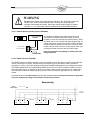
2 Installation
This section contains basic installation information concerning choice of control and servomotor environment,
wiring specification and connection details.
WARNING
EXPLOSION OR FIRE HAZARD
CAN CAUSE PROPERTY DAMAGE,
SEVERE INJURY OR DEATH
To prevent possible hazardous burner operation, verification of safety
requirements must be performed each time a control is installed on a burner, or
the installation modified in any way.
This manual may cover more than one model in the PPC6000 controls. Check for
Additional Information at the end of this chapter.
This control must not be directly connected to any part of a Safety Extra Low
Voltage (SELV) circuit.
WHEN INSTALLING THIS PRODUCT:
Read these instructions carefully and ensure you fully understand the product requirements. Failure to
follow them could damage the product or cause a hazardous condition.
Check the ratings given in these instructions to ensure the product is suitable for your application.
After installation is complete, check the product operation is as described in these instructions
CAUTION
Disconnect the power supply before beginning installation to prevent electrical
shock, equipment and/or control damage. More than one power supply
disconnect may be involved.
Wiring must comply with all applicable codes, ordinances and regulations.
Loads connected to the PPC6000 series must not exceed those listed in the
specifications as given in this manual.
All external components connected to the control must be approved for the
specific purpose for which they are used.
18
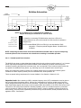
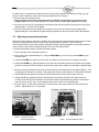
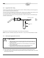
2.1
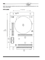
Mounting details for the PPC6000 control
6.26” (159mm)
0.75”
(19mm)
4.65”
(118mm)
3.15”
(80mm)
6.93” (176mm)
A Template for mounting is provided at the end of this manual for convenience. See Section 8.
There are two versions of the control, one that is intended to be mounted inside of a burner control cabinet, the
other which has provision for conduit storage of field wiring etc. that can be mounted without the need for a
burner control cabinet. If the version which is designed to be fitted inside of a burner control cabinet is being
used the cabinet should have a minimum protection level of NEMA1 (IP40) for indoor use or NEMA3 (IP54) for
outdoor use.
The control can be mounted in any attitude; clearances of a least 2.36-inch (60mm) should be left around the
unit to allow sufficient space for wiring and to ensure reliable operation.
The ambient operating temperature range of the equipment is 0 to 60°C (32 to 140°F). Refer to section 7 for
more details.
Terminal Block PB
Terminal Block PA
Terminal Block PE
Screen
Termination
Clamps
19
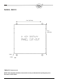
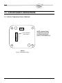
2.2
Mounting details for the display module
A Template for mounting is provided at the end of this manual for convenience. See Section 8.
NOTE: The four (4) M4 clearance holes are the mounting holes for the display. After removing the
back cover, carefully remove the four brass hex standoff’s to secure the display to the panel.
The display should be mounted on the front of the burner cabinet, or similar accessible location.
It extends for 31mm (1.22 inches) behind the panel, and 4mm (0.16 inches) in front of the panel.
The maximum allowable panel thickness is 7mm (0.275 inches).
8mm
8mm
REMOVE AND REUSE
For Mounting
8mm
The display is held in using the four brass standoffs. The panel is cut out inside the four mounting holes only.
Remove the four brass standoffs, insert the screw studs through the mounting holes, then re-install the brass
standoffs. Do not over tighten the standoffs.
A Template for mounting is provided at the end of this manual for convenience. See Section 8.
20
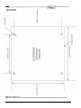
2.3
Mounting details for optional Oxygen Probe Interface unit, NX02INT
A Template for mounting is provided at the end of this manual for convenience. See Section 8.
The optional oxygen probe interface unit is designed to be fitted either within a control cabinet or without a
control cabinet; the unit has a protection level of NEMA4 (IP65) providing suitable conduit glands are used.
The interface unit can be mounted in any attitude, clearances should be maintained around the conduit entries
to the unit to allow sufficient space for wiring etc. the ambient operating temperature range is 0 to 60°C (32 to
140F). The unit MUST be grounded (earthed) to maintain electrical safety and ensure reliable operation.
Enclosure is 2.8” (71mm) deep
Power CANbus and
Probe cable entry
21
2.4
The oxygen trim option
CAUTION
2.4.1
Use extreme care when handling the oxygen probe and wear heatproof gloves.
Ensure the burner is off before removing the oxygen probe from the flue.
If the boiler is to be operated with the probe removed, fit the blanking cover
supplied since dangerous levels of carbon monoxide may be present in the flue.
Oxygen Probe description
The oxygen trim / monitoring function is designed to be used with either an NXO2PK4, NXO2PK6, or
NXO2PK8 oxygen probe. The probe offers fast, accurate response and good reliability when mounted in
accordance with the guidelines in this section.
The probe is available in three different sizes.
2.4.2
Installation of oxygen probe
SEE DIM. B.
Model
A
no.
NXO2PK4 173(6.81)
NXO2PK6 362(14.25)
NXO2PK8 716(28.19)
CLEARANCE REQUIRED TO INSTALL
& REMOVE FROM FLUE. SEE DIM.C.
Dimension
B
C
215(8.5)
406(15.99)
757(29.8)
D
295(11.6)
486(19.13)
873(32.95)
470(18.5)
659(25.95)
1013(39.88)
246(9.7)
30º
2 TYP.(0.08)
Ø 20 FLEXIBLE
SIDE VIEW
CASE MATERIAL: CORROSION RESISTING STEEL.
FINISH: SELF.
35(1.4)
TOTAL ASSEMBLY WEIGHTS: MODEL NXO2PK4 - 2.95kg (6.5lb)
MODEL NXO2PK6 _ 3.40kg (7.5lb)
MODEL NXO2PK8 - 4.24kg (9.4lb)
FLUE GAS
TO MOUNT ON FLAT WALL FLUES (STACKS) SEE DRG. No.HG220371E PART A.
TO MOUNT ON CYLINDRICAL WALL FLUES SEE DRG. No.HG220371E PART B.
FOR PROBE MOUNTING POSITIONS SEE DRG. HG220559E.
ALL DIMENSIONS IN MILLIMETRES
INCH EQUIVALENTS ARE IN ( )
22
CLEARANCE REQUIRED TO
& REMOVE FROM FLUE. SEE DIM. D.
SEE DIM. A.
96(3.8)
CONDUIT ENTRY.
CALIBRATION GAS CONNECTION.
*0202+
PROBE T/CPROBE T/C+
INTERNAL
CONNECTIONS
FLUE T/CFLUE T/C+
HEATER
HEATER
CUSTOMER
CONNECTIONS
COMPONENT SIDE VIEW OF INTERNAL
ELECTRICAL INTERCONNECTION PCB.
* NOTE: 02- CONNECTED TO PROBE BODY. ie. GROUND
2.4.3
Mounting the oxygen probe
The probe must be mounted in a manner that ensures that the flue gases pass into the gas tube at its open
end and out of the tube at the flange end. Furthermore, if possible, the flange should be vertical with the gas
tube angled downwards to ensure that particulates do not build up within the sample tube. Probe mounting
with the flange horizontal is acceptable. Inverted probe mounting is not acceptable.
C
2
VERTICAL FLUE
PROBE MOUNTED ON SIDE
TOP VIEW
SECTION ON E-E.
ACCEPTABLE MOUNTING
HORIZONTAL FLUE
PROBE MOUNTED ON SIDE.
PREFERRED MOUNTING
1
FLUE
GAS
D
SECTION
ON D-D.
FLUE
GAS
FLUE
GAS
D
SECTION ON C-C
PROBE MOUNT HOLES SHOWN
(SEE HG220371)
NOTE ORIENTATION RELATIVE
TO FLUE GAS FLOW.
F
F
E
E
FLUE
GAS
30
SIDE VIEW
SECTION ON F-F.
C
PROBE MOUNT HOLES(SEE HG220371)
NOTE ORIENTATION RELATIVE TO
FLUE GAS FLOW.
TOP VIEW
SECTION ON A-A.
UNACCEPTABLE MOUNTING
SIDE VIEW
B
B
FLUE
GAS
HORIZONTAL FLUE
PROBE MOUNTED UNDERNEATH.
FLUE
GAS
3
A
PROBE MOUNT HOLES SHOWN
(SEE HG220371). HOLE ORIENTATION
RELATIVE TO FLUE GAS FLOW.
4
A
NON-PREFERRED MOUNTING
FLUE
GAS
HORIZONTAL FLUE
PROBE MOUNTED ON TOP.
DO NOT FIT PROBE IN
THIS POSITION.
SECTION ON B-B
SIDE VIEW.
There are two types of flange available (see the drawing over the page). With either flange the vertical center
line of the flange shown on the drawing should correspond to the gas flow direction.
6 stainless steel M6 x 20mm socket cap screws are provided for probe attachment.
The probe flange temperature must be maintained at the temperature of the flue wall by repacking or adding
lagging, which may have been removed to mount the probe. Sulphate condensation will occur if the flue wall
of an oil fired boiler falls below approximately 130°C. The sulphate problem does not occur in gas-fired
installations, but vapor may cause problems due to condensation if the temperature of the flue gas falls below
100°C.
The maximum flue gas temperature is 1004ºF (540ºC).
23
DIRECTION OF
FLUE GAS FLOW
LA220427 Assembly
3 (1/8") FILLET WELD
ALL ROUND
FLUE WALL
30¦
FLUE APERTURE
COVER
Ø 73.0(2.87")
CUT OUT IN FLUE.
M6 PROBE
MOUNT HOLES
CL
GASKET
20
VIEW OF MOUNTING PLATE
WITH COVER
(0.78")
WELD FLANGE
PROBE MOUNT
ALL DIMENSIONS IN MILLIMETRES
INCH EQUIVALENTS ARE IN ( )
MATERIAL: MILD STEEL
FINISH: ZINC PLATE.
PROBE MOUNT SYSTEM - CYLINDRICAL
OR FLAT WALL FLUE.
The probe end cap carries a removable 20mm (3/4”) flexible conduit fitting to enable probe replacement
without wiring. The 2 hexagonal caps visible on the probe rear face are there to cover the calibration gas port
and the sample gas port. The latter is merely a tube that passes directly into the flue to enable gas samples to
be drawn or flue temperatures to be taken using other instrumentation. Both ports must be kept sealed during
normal operation for safety and accurate performance.
2.4.4
Mounting arrangements for Temperature and Steam pressure sensors
For full technical specifications of sensors see sections 2.4.5 and 2.4.6
2.4.5
Boiler temperature sensors
(10.63”)
(7.87”)
½” Conduit Adaptor PN 35-336
24
The temperature sensor has a protection level of NEMA4, providing suitable conduit glands are used and can
be mounted in any attitude. It has been designed for mounting into a well, or pocket, that has been inserted
into the boiler shell. When choosing the position of the well, care should be taken to ensure that the sensor
operates within its environmental specifications, and that the position will allow measurements, and
subsequent control actions, to be correlated to other devices e.g. auxiliary safety stats.
The ambient operating temperature range is 0 to 60°C (0 to 140°F).
The unit MUST be grounded (earthed) to maintain electrical safety and ensure reliable operation.
2.4.6
Steam pressure sensors
When fitting the sensor, care should be taken to ensure that the sensor
operates within its environmental specifications. An important issue is
the heating effect of the steam. Also, the sensor should be connected to
the process in such a way that readings, and subsequent control
actions, can be correlated to other devices e.g. the boiler pressure dial
gauge and any auxiliary safety stats.
Steam Pressure sensors must be mounted in a vertical attitude to
ensure water vapor does not collect inside the sensor. Additional
devices, e.g. a “pig tail” feed pipe, may be required to reduce the
possibility of moisture reaching the sensor during normal operation.
Maintenance procedures should ensure that the sensor is inspected for
evidence of condensates from the process collecting at the sensing
point. If evidence of condensate is found, then preventative action must
be taken to eliminate the cause.
The ambient operating temperature range is 0 to 70°C.
The unit MUST be earthed to maintain electrical safety and ensure
reliable operation.
The conduit connection for steam pressure sensors is PG9, an adaptor for ½” NPSL is available.
Fireye ½” Conduit Adaptor P/N35-371.
25
2.5
2.5.1
Option link selection (PPC6000)
General (Access to jumper’s and fuse’s is gained by removing the back cover of the PPC6000)
Wickmann-Littlefuse
PN 3701100043
1 AMP (Fast Acting)
( to protect 5V DC circuit)
Alternate Source:
Mouser Electronics
PN 576-371100000
Bussmann - S504 series
P/N GMD-630 (Time Delay) for 115V
P/N GMD-315 (Time Delay) for 230V
( to protect 24V circuit)
Alternate Source:
Mouser Electronics
PN 504-GMD-630mA
PN 504-GMD-315mA
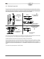
The PPC6000 has a number of option selection links, located on the circuit board. The function and settings
are marked on the board alongside each link. These links must be set to the correct position before
power is applied to the control. On some versions of the control additional details reference the option links
and fuses are provided on a label attached to the mounting ‘base’, from which the product must be removed to
gain access.
2.5.2
Line supply voltage (LK1 - 4) (PPC6000)
WARNING
Incorrect setting of the Links WILL damage or destroy the unit.
The possible supply voltages are shown below, together with the necessary fuse rating. The correct fuse (type
and rating) must be fitted; failure to do so may result in damage to the control.
Supply voltage (V)
120
230
Links required
LK1 and LK3
LK2 and LK4
Fuse rating (mA)
630 anti-surge – TIME DELAY
315 anti-surge – TIME DELAY
26
2.5.3
SENS IN and SENS SUPP (boiler temp/pressure sensor) (PPC6000)
If a boiler pressure/temperature sensor or modulation potentiometer is used, links JP3 and JP1 must be set to
suit the type of sensor and voltage requirement. For example:
+30v
OUT
+30v
OUT
2.5.4
JP3
+5v
JP1
JP3
IN
+5v
JP1
IN
For a 4-20mA loop-power sensor, choose a +30V supply.
For a 4-20mA loop-power sensor, choose current (IN) input.
For a 0-5V modulation signal, choose a +5V supply
For a 0-5V modulation signal, choose voltage (OUT) input
REMOTE SETPOINT (PPC6000)
If the remote setpoint or track signal is being used, link JP2 must be set to suit the type of signal. For
example:
OUT
OUT
2.5.5
JP2
IN
JP2
IN
For a current input set JP2 to IN position to ensure burden resistor is connected.
For a voltage input signal set JP2 to OUT to ensure burden resistor is not connected.
RS485 serial communications termination resistor (PPC6000)
JP4
OUT
OUT
IN
2.5.6
IN
Please note that the RS485 serial communications supplied as part of the basic
control is non-isolated, the termination resistor is selected by JP4. The two
controls at the end of the communications bus should have this link set to the
IN position. All other controls should have the link set to the OUT position. If
only two controls are on the communications bus, set the links on both controls
to the IN position.
RS485 serial communications termination resistor (daughter board)
RS485
OUT
OUT
IN
IN
The optional daughter board provides an isolated RS485 serial communication
function, the termination resistor is selected by the RS485 (JP2) jumpers on
the daughter board, but the terminals are provided as part of the
PPC6000. The two controls at the end of the communications bus should have
both of the RS485 (JP2) links set to the IN position. All other controls should
have the links set to the OUT position. If only two controls are on the
communications bus, set the links on both controls to the IN position.
27
Note: All wiring to terminals PA & PB are low voltage and must be
braided shielded wire per table 2.6.1A. Wiring to terminals “PE” are
line voltage. The maximum wire size is 16AWG (19.3mm) for all
terminals.
Note: PE7 & PE8 provide purge and low fire position signals to the
flame safeguard control. These outputs MUST NOT have a load
greater than 30mA (i.e. relays, lamp, etc.), damage to the PPC6000
will result. This connection MUST be braided shielded wire.
28
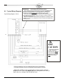
2.6
Wiring
Typical Schematic
An abbreviated typical wiring schematic diagram showing the PPC6000 Parallel Positioning Controller, YB110
Flame Safeguard Control and YZ300 Expansion Module can be found in section 9.6in this manual.
This diagram is for reference only and may not meet all national or local codes. In all cases, local
codes prevail with respect to the final installation of this product.
2.6.1
General
READ THIS FIRST!!!!
There are numerous mentions of “….overall braided shielded (screened) wire” throughout this
manual. This is an important aspect to reliable operation. Table 2.6.1-A lists the only
approved wire for this control. While one of the specifications relating to shielded wire
indicates the amount of coverage (0-100%), this is not the only factor in selecting wire. While it
is true, “foil and drain” shielded wire specifications indicate 100% coverage as compared to
approximately 85% for braided type, the cross sectional area of the braid provides the
required noise immunity. Also, the special grounding clamp bars on this control do not provide
adequate connection to foil shield. In fact most foil shields do not conduct on the surface.
Using the “drain” wire to a ground stud does not properly protect the control.
CAUTION
Disconnect the power supply before beginning installation to prevent electrical
shock, equipment and/or control damage. More than one power supply
disconnect may be involved.
Wiring must comply with all applicable codes, ordinances and regulations.
Loads connected to the PPC6000 series, optional daughter board and optional
oxygen probe interface must not exceed those listed in the specifications as given
in this manual.
Ensure the maximum total load on the CANbus cabling (servo-motors, display
etc) is within the specifications of the PPC6000 and for the cable being used.
This control MUST NOT be directly connected to any part of a Safety Extra Low
Voltage (SELV) circuit.
WIRING INSTALLATION MUST BE CARRIED OUT BY A COMPETENT ELECTRICIAN AND IS SUBJECT
TO I.E.E. WIRING REGULATIONS (BS 7671:1992), NEC AND/OR LOCAL STANDARDS, WHICH MAY
PREVAIL.
HAZARDOUS VOLTAGES MUST BE ISOLATED BEFORE SERVICE WORK IS CARRIED OUT.
The PPC6000 unit MUST be mounted within a ‘burner cabinet’ or similar and MUST be grounded (earthed) to
the overall enclosure to ensure safe and reliable operation.
Do not use a green or green/yellow conductor for any purpose other than ground (earth). The metal body of all
component parts MUST be connected to ground (earth) using a green or green/yellow conductor.
29
The screen of the signal cable MUST not be used to provide the safety ground (earth), a separate connection
using the largest cross-sectional area green or green/yellow ground (earth) wire possible MUST be made.
The screen termination clamps on the control are only provided to allow connection of the cable screens to the
PPC6000 they do not provide strain relief. The signal cable screens MUST be connected at the screen
termination clamps only, unless stated otherwise. Screened cables MUST be of the ‘copper braid shield’
type and not ‘foil with drain wire’, the cross section of the drain wire is insufficient to provide correct screening
of the signals and there is also no provision to connect the foil or drain at the PPC6000.
Secure all cables carried in conduit at both ends using a suitable anchorage method in the cabinet.
All cabling that is required to operate at above 50v must be multi-strand single conductor (core), PVC
insulated, 16 AWG (19/0.3mm) and should meet the requirements of I.E.C. 227 or I.E.C. 225, NEC
To comply with EMC requirements, wire the control and any optional units using the specified cable sizes and
screen connections observing any maximum cable length limitations. The manufacturer of this equipment
recommends the use of bootlace ferules on all wire ends, as a “best practice”.
Bootlace
Ferules
The equipment described in this manual has been tested for compliance to the CE and UL directives listed in
the section headed ‘approvals’. However, once connected to a burner and other associated controls it is the
responsibility of the installer to ensure the complete installation meets the requirements of the UL or CE
directives relevant to the particular installation.
IMPORTANT: Wiring Guidelines
NOTE: Interposing terminal blocks should be avoided when shielded cable is required. Interposing
terminals present a risk of electrical noise interference resulting in unreliable operation.
All wiring to this control must comply with National, State and Local electrical codes. In general, all insulation
must meet or exceed the highest voltage present on any conductor in a conduit, raceway or panel, e.g. 480
volt motor wiring would require at least 600-volt insulation. Consult the National Electric code for guidance.
IMPORTANT: Low Voltage (vertical terminal strips)
All low voltage circuits and communication wire must be fully shielded braided type wire of the specified gauge
and number of conductors. Table 2.6.1-A provides the only approved wire for this application. No “or
equal” is provided. Use of wire not approved by Fireye may VOID warranty.
All wiring to terminal block “PA” & “PB” as well as to any optional daughter board (e.g. VSD) and the
Power/CANbus wiring to the display, must be fully shielded braided wire per Table 2.6.1-A.
Under no circumstances should these input/outputs be connected to mains potential.
Connection of any voltage above 5 volts to these terminals will damage or destroy the unit.
30
Alpha
Carol
Belden
(conductors)
(conductors)
(conductors)
4
2
4
4
300V
25164
25162
---
9940
600V
25524
25522
C2688
7895A*
* NOTE:
2
2
If Belden 7895A wire is used it will be necessary to use 2 conduit
adapters per device if wired as a “daisy chain.”
See Table 2.6.1-D
Table 2.6.1-A
IMPORTANT: Line Voltage (horizontal terminal bottom (PE) must NOT be shielded wire.
All line voltage wiring must be no greater than 16 AWG (19/0.3mm) THHN, TFFN or equal.
The following table provides a guide for converting from NEMA Enclosure Type Numbers of IEC Enclosure Classification Designations.
The NEMA Types meet or exceed the test requirements for the associated IEC Classifications; for this reason the table should not be used
to convert from IEC classifications to NEMA Types and the NEMA to IEC conversion should be verified by test.
NEMA Enclosure Type
Number
IEC Enclosure
Designation
1
IP10/IP40/IP20
2
IP11
3
IP54
3R
IP14
3S
IP54
4 and 4X
IP56
5
IP52
6 and 6P
IP67
12 and 12K
IP52
13
IP54
Table 2.6.1-B
International Wire Size Conversion Table: All dimensions shown are as accurate as possible, however, when converting
AWG, SWG, inches and metric dimensions, round-off errors do occur. Wire and cable also vary depending upon
manufacturer.
American or
Brown &
Sharpe’s
AWG
16
British
Standard
SWG
-
Nominal
Conductor
Diameter (0)
(inches)
0.051
Fractional
Equivalent
(inches)
-
Nominal
Conductor
Diameter (0)
(mm)
1.30
Cross Sectional
Conductor Area
Sq mm
(mm2)
1.33
18
19
0.040
-
1.02
0.82
16 x .010
7 x .4
20
21
0.032
-
0.81
0.52
10 x .010
16 x .2
24
25
0.020
-
0.51
0.20
7 x .008
7 x .2
Table 2.6.1-C
31
** Stranded Wire Construction
Number of Strands
x Diameter of Strands
(inches)
(mm)
26 x .010
19 x .30
CONDUIT CONNECTOR ADAPTERS
Metric to ½ inch NPSL Female
Device
Fireye Part Number
NXC04 Servomotor
NXC12 Servomotor
NXC20 Servomotor
NXC40 Servomotor
NXIATS Inlet Air Sensor
NXO2INT Oxygen Interface
All O2 Probe Assembly
35-321
35-321
35-322
35-372
35-336
35-372
35-372
Table 2.6.1-D
2.6.2
Grounding cable screens
Two screen termination clamps are provided on the PPC6000 for termination of cable screens (copper braid
type) where necessary, if the unit is used with a daughter board the screens of these cables MUST also be
terminated to the cable clamps and the screen and associated insulation left on the cable until as close as
possible to the terminals to which they are connected. Where screened cables are required to run through one
unit to connect to another a terminal is provided to allow the screens to be connected, by forming a ‘tail’ with
the braided screen of each cable, the length of unscreened cable should be kept as short as possible but in
any case MUST not exceed 13/16” (30mm), per cable ‘tail’.
Connect all signal cable ‘braid’ screens to ground (earth) using the screen termination clamps provided on the
control. Connect all cable screens to ground (earth) at the control only, with the exception of the cables that
connect the temperature and pressure sensors where fitted. Where the wiring is ‘run through’ one unit to
connect to another terminals are provided to ensure the screen connection is maintained.
(1)
The cable should be prepared by cutting around the
outer insulation, taking care not to damage the screen
(1).
(2)
Pull the insulation apart to expose 3/8 in. (10 mm) of the
screen (2).
3/8in. (10mm)
(3)
2.6.3
Slide the exposed braid screen down between the
vertical cable clamps on the PPC6000. The conductive
cushion provides grounding (earthing).
GROUND (EARTH) connection
The PPC6000 MUST be connected to ground (earth); the connection should be made at the stud with the tag
showing the Ground (earth) symbol. This connection is required to maintain the overall electrical safety of the
installation and ensure the EMC performance of the equipment; failure to comply with the wiring requirements
will affect the performance of the system and may cause a hazardous condition to occur. Ensure that a good
electrical connection is made between both the unit and the burner panel then between the burner panel and
ground (earth). Where necessary, scrape any paint away from connection points and use shake-proof
washers to ensure a reliable electrical connection. Always use the largest cross-sectional area ground (earth)
wire possible.
32
2.6.4
Ground (earth) Connection (display unit)
The display unit MUST be connected to ground (earth); the connection should be made at the stud with the tag
showing the Ground (earth) symbol. This connection is required to maintain the overall electrical safety of the
installation and ensure the EMC performance of the equipment; failure to comply with the wiring requirements
will affect the performance of the system and may cause a hazardous condition to occur. Ensure that a good
electrical connection is made between both the unit and the burner panel then between the burner panel and
ground (earth). Where necessary, scrape any paint away from connection points and use shake-proof
washers to ensure a reliable electrical connection. The screen of the signal cable MUST not be used to
provide the electrical safety ground (earth), a separate connection using the largest cross-sectional area
ground (earth) wire possible MUST be made.
If the display unit is mounted into a burner cabinet door ensure there is a good electrical connection between
the door and the main cabinet in addition to a good electrical contact between the display unit and the door.
2.6.5
Terminal Designation
All terminals within the system have ‘unique’ terminal designations to reduce the possibility of wiring errors.
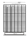
This information is tabulated below:
Terminal Number
Location
Function
Voltage Range
PA1
PA2
PA3
PA4
PA5
PA6
PA7
PA8
PA9
PA10
PA11
PA12
PPC6000
PPC6000
PPC6000
PPC6000
PPC6000
PPC6000
PPC6000
PPC6000
PPC6000
PPC6000
PPC6000
PPC6000
24 – 40Vac
24 – 40Vac
0 – 5V
0 – 5V
0 – 5Vdc
0 – 5Vdc
0 – 5Vdc
0 – 5Vdc
0 – 5Vdc
0 – 30Vdc
0 – 5V
0 – 5Vdc
PA13
PPC6000
24Vac Supply for Servos, Display etc.
24Vac Supply for Servos, Display etc.
CAN + (CANbus)
CAN - (CANbus)
Digital Input 1
Digital Input 2
Digital Input 3
Digital Input 4
High purge request
Auto
Digital Input Common
Analog Input 5 (Aux mod./remote
Setpoint)
Sensor Supply (+30Vdc)
PB1
PB2
PB3
PB4
PB5
PB6
PB7
PB8
PB9
PB10
PB11
PB12
PB13
PPC6000
PPC6000
PPC6000
PPC6000
PPC6000
PPC6000
PPC6000
PPC6000
PPC6000
PPC6000
PPC6000
PPC6000
PPC6000
24Vac Supply for Servos, Display etc.
24Vac Supply for Servos, Display etc.
CAN + (CANbus)
CAN - (CANbus)
RS485 comms A (+)
RS485 comms B (-)
RS485 comms 0 Volt (not shield)
Sensor Supply (30V)
Sensor Input
Sensor 0 Volt (not shield)
Isolated comms (Modbus) A+
Isolated comms (Modbus) B Isolated 0 Volt (Modbus)
24 – 40Vac
24 – 40Vac
0 – 5V
0 – 5V
0 – 5V
0 – 5V
0 – 5V
0 – 5V
0 – 5V
0 – 5V
0 – 5V
0 – 5V
0 – 5V
PE1
PE2
PE3
PE4
PE5
PPC6000
PPC6000
PPC6000
PPC6000
PPC6000
PPC6000 neutral (L2)
PPC6000 live (L1)
Controlled Shutdown relay output
Alarm Relay
S/S Relay
33
0-30Vdc
115 - 230Vac
115 - 230Vac
0 – 230Vac
0 – 230Vac
0 – 230Vac
Terminal Number
PE6
PE7
PE8
PE9
PE10
PE11
PE12
Location
PPC6000
PPC6000
PPC6000
PPC6000
PPC6000
PPC6000
PPC6000
Function
S/S Relay
Ign Prove (Low Fire output)
Purge Prove (High Purge output)
Profile 1 Select
Profile 2 Select
Profile 3 Select
Profile 4 Select
Voltage Range
0 – 230Vac
0 – 230Vac
0 – 230Vac
0 – 230Vac
0 – 230Vac
0 – 230Vac
0 – 230Vac
PK1
PK2
PK3
PK4
PK5
On Servomotor
On Servomotor
On Servomotor
On Servomotor
On Servomotor
24Vac Supply
24Vac Supply
CAN +
CAN Screen connection
24 – 40Vac
24 – 40Vac
0 – 5V
0 – 5V
Not applicable
PL1
PL2
PL3
PL4
PL5
PL6
Oxygen Interface
Oxygen Interface
Oxygen Interface
Oxygen Interface
Oxygen Interface
Oxygen Interface
115 - 230Vac
115 - 230Vac
0 – 5V
0 – 5V
0 – 5V
0 – 5V
Oxygen Interface
Unit Supply (live L1)
Unit Supply (neutral L2)
CAN +
CAN Analog input 2 (NA - future)
Analog input 1 (4 – 20mA O2 third
party probe.
Analog input 0v
PL7
PM2
PM3
PM4
PM5
PM6
PM7
PM8
PM9
Oxygen Interface
Oxygen Interface
Oxygen Interface
Oxygen Interface
Oxygen Interface
Oxygen Interface
Oxygen Interface
Oxygen Interface
Oxygen Cell mV (-)
Oxygen Cell mV (+)
Oxygen Cell Temperature (-)
Oxygen Cell Temperature (+)
Flue Temperature (-)
Flue Temperature (+)
Heater Output
Heater output
0 – 100mVdc
0 – 100mVdc
0 – 100mVdc
0 – 100mVdc
0 – 100mVdc
0 – 100mVdc
0 – 40Vac
0 – 40Vac
0 – 5V
NX610 Display Relays – General Purpose Shown
For Alarm, see Section 5.5.1 Option 17.x Table A
PR1
PR2
PR3
PR4
PR5
PR6
PR7
PR8
PR9
Display Unit
Display Unit
Display Unit
Display Unit
Display Unit
Display Unit
Display Unit
Display Unit
Display Unit
Relay output 1 normally open
Relay output 1 normally closed
Relay output 1 common
NO CONNECTION
Relay output 2 normally open
Relay output 2 normally closed
Relay outputs 2 & 3 common
Relay output 3 normally closed
Relay output 3 normally open
0 – 250V
0 – 250V
0 – 250V
N/A
0 – 250V
0 – 250V
0 – 250V
0 – 250V
0 – 250V
NXTSD104 Touchscreen Display Relays – General Purpose Shown
For Alarm, see Section 5.5.1 Option 17.x Table C
PR1
PR2
PR3
PR4
PR5
PR6
Display Unit
Display Unit
Display Unit
Display Unit
Display Unit
Display Unit
Relay output 1 common
Relay output 1 normally closed
Relay output 1 normally open
Relay output 2 common
Relay output 2 normally closed
Relay output 2 normally open
34
0 – 250V
0 – 250V
0 – 250V
0 – 250V
0 – 250V
0 – 250V
Terminal Number
PR7
PR8
PR9
PR10
Location
Display Unit
Display Unit
Display Unit
Display Unit
PR11
Display Unit
PR12
Display Unit
PT1
PT2
PT3
PT4
STUD
Display Unit
Display Unit
Display Unit
Display Unit
Display Unit
PZ1
PZ2
PZ3
PZ4
PZ5
PZ6
PZ7
Daughter Board
Daughter Board
Daughter Board
Daughter Board
Daughter Board
Daughter Board
Daughter Board
PZ8
PZ9
Daughter Board
Daughter Board
PZ10
PZ11
PZ12
PZ13
PZ14
PZ15
PZ16
PZ17
PZ18
Daughter Board
Daughter Board
Daughter Board
Daughter Board
Daughter Board
Daughter Board
Daughter Board
Daughter Board
NXDBVSD
2.6.6
Function
Relay output 3 common
Relay output 3 normally closed
Relay output 3 normally open
Relay output 9 common (TSD104
only)
Relay output 9 normally closed
(TSD104 only)
Relay output 9 normally open
(TSD104 only)
Voltage Range
0 – 250V
0 – 250V
0 – 250V
0 – 250V
24Vac Supply
24Vac Supply
CAN +
CAN Screen connection
24 – 40Vac
24 – 40Vac
0 – 5V
0 – 5V
Not applicable
Channel 1 output [4-20mA] (-)
Channel 1 output [4-20mA] (+)
Channel 2 output [4-20mA] (-)
Channel 2 output [4-20mA] (+)
Channel 3 output [4-20mA] (-)
Channel 3 output [4-20mA] (+)
Encoder (proximity counter)
Feedback 1
Encoder Supply
Encoder (proximity counter)
Feedback 2
Encoder Supply
Encoder Feedback 3
Channel 1 Feedback [4-20mA] (-)
Channel 1 (+) & Channel 2 (-)
Channel 2 Feedback [4-20mA] (+)
Relay output 7 common
Relay output 7 normally open
Relay output 8 common
Relay output 8 normally open
0 – 250V
0 – 250V
0 – 20V
0 – 20V
0 – 20V
0 – 20V
0 – 20V
0 – 20V
0 – 12V
12Vdc
0 – 12V
12Vdc
0 – 12V
0 – 5Vdc
0 – 5Vdc
0 – 5Vdc
0 – 40V
0 – 40V
0 – 40V
0 – 40V
LINE and NEUTRAL supply (PPC6000) PE1 & PE2
WARNING
Incorrect setting of the Supply Voltage Links WILL damage or destroy the unit.
NEUTRAL
PE1
MAX 8A
PE 2
LIVE
The LINE and NEUTRAL supplies must be connected using
multi-strand single conductor (core) PVC insulated 16 AWG
(19/0.3mm) wire. The live connection MUST be fused with a
maximum rating as shown.
35
NOTE: Line (live) is term PE2. If a fuse greater than 8A is fitted, each relay (safety shutdown and
controlled shutdown) output supplied via this terminal MUST be separately fused at 8A maximum, to
protect the relay contacts from ‘welding’. It is also recommended that the alarm relay be fused at 4A
maximum to protect the relay contacts from ‘welding’, which may cause incorrect alarm indication.
2.6.7
Safety Shutdown output (PPC6000)
The safety shutdown relay output must be
connected using multi-strand single conductor
(core) PVC insulated 16 AWG (19/0.3mm) wire.
This output must be connected to ensure the
burner will shutdown if no output is present.
MAX 8A *
SAFETY SHUTDOWN PE 5
BURNER
CONTROLLER
SAFETY SHUTDOWN PE 6
* If a control panel fuse greater than 8A is
fitted, the safety shutdown output terminal
MUST be separately fused at 8A maximum.
2.6.8
Controlled Shutdown Relay Output (PPC6000)
WARNING
Any external limit device, if fitted must be connected into the controlled shutdown
circuit, unless connected into the auxiliary inputs and the correct function selected.
If a limit device is fitted into the controlled shutdown circuit it must be capable of
supplying the total current required by devices connected to this circuit.
Any limit device connected to the PPC6000 series control must be approved for
the specific purpose for which it is being used.
Wiring must comply with all applicable codes, ordinances and regulations.
MAX 8A*
The controlled shutdown relay output must be
connected using multi-strand single conductor
(core) PVC insulated 16 AWG (19/0.3mm) wire.
If a control panel fuse greater than
8A is fitted, the controlled shutdown circuit MUST be separately fused at 8A maximum to
protect the relay contacts from ‘welding’.
SHUTDOWN PE3
2.6.9
Alarm Relay output – RELAY 4 (on the PPC6000)
(See option parameter 14.7 for further programming options.)
The alarm relay output must be connected
using multi-strand single core PVC
insulated 16 AWG (19/0.3mm) wire. This
ALARM OUTPUT PE 4
(line voltage) output must only be used for
indication, as it is not fail-safe. If a fuse
greater than 4A is fitted in the supply to
the control, it is recommended the alarm relay output be separately fused at 4A maximum.
NOTE: Relays 1 to 3 are (optionally) provided on the display board. Relays 5 and 6 are reserved for
future products. Relays 7 and 8 are (optionally) provided on the daughter board.
NEUTRAL (N) PE 1
36
2.6.10 Auxiliary Relay Outputs (display)
Fuses not exceeding 4A must protect all relay outputs. If a control
panel fuse greater than 4A is fitted, the relay common MUST be
separately fused at 4A maximum. Where the total relay current
exceeds 4A, fit a separate fuse on each relay output to achieve this.
These outputs must be connected using multi-strand single core PVC
insulated 16 AWG (19/0.3mm) wire. Since this cable may be run in
conduit with high voltage wiring, its voltage rating must exceed the
maximum voltage carried by any other cable connected to the control or
run in the same conduit.
The 3 auxiliary relays provide volt free change over contacts. Two of the
relays (2&3) share a common voltage source. The relays are separated
on the circuit board to allow either the pair sharing the common or the
single relay to operate at high voltage while the other(s) operate at low
voltage. Alternatively all relays may operate at the same voltage.
The relay functions can be set via the option parameter, or via the
programmable blocks. See Option 17.x for important details
regarding these relays.
RELAY 1 NORMALLY OPEN PR 1
RELAY 1 NORMALLY CLOSED PR 2
RELAY OUTPUTS 1 COMMON PR 3
NO CONNECTION PR 4
RELAY 2 NORMALLY OPEN PR 5
RELAY 2 NORMALLY CLOSED PR 6
RELAY 2 & 3 COMMON PR 7
RELAY 3 NORMALLY CLOSED PR 8
RELAY NORMALLY OPEN PR9
NOTE: The above is for Alarm
Function – See Option
14.1, 14.2 and 17.x for
important details
2.6.11 Fuel Select /Profile Select Input/Purge and Ignition Prove Outputs (PPC6000)
The four fuel-profile select inputs are designed for operation at between 120 & 230Vac. (relevant Engineer’s
Keys EK11-EK14, section 6.6.2)
9 10 11 12
O
8
/
7
FUEL/PROFILE 4
6
FUEL/PROFILE 3
5
FUEL/PROFILE 2
4
FUEL/PROFILE 1
L
3
PURGE PROVE
2
IGNITION PROVE
1
N
PE
These inputs must be connected using multi-strand single
core PVC insulated 16 AWG (19/0.3mm) wire.
Since this cable is to be run adjacent to, and/or in the same
conduit as high voltage wiring, its voltage rating must
exceed the maximum voltage carried by any other cable
connected to the control or run in the same conduit.
Note: PE7 and PE8 provide purge and low fire position signals to the flame safeguard control. These outputs
MUST NOT have a load greater than 30mA (i.e. relays, lamp, etc.), damage to the PPC6000 will result.
READ THIS FIRST!!!!
There are numerous mentions of “….overall braided shielded (screened) wire”
throughout this manual. This is an important aspect to reliable operation. Table
2.6.1-A lists THE ONLY APPROVED WIRE for this control. While one of the
specifications relating to shielded wire indicates the amount of coverage (0-100%),
this is not the only factor in selecting wire. While it is true, “foil and drain” shielded
wire specifications indicate 100% coverage as compared to approximately 85% for
braided type, the cross sectional area of the braid provides the required noise
immunity. Also, the special grounding clamp bars on this control do not provide
adequate connection to foil shield. In fact most foil shields do not conduct on the
surface. Using the “drain” wire to a ground stud does not properly protect the control.
NOTE: If wire entrances to terminals face inward (under the cover), then these
wires require braided shielded wire. If the terminals face outward, NO braided
wire is to be used.
37
2.6.12 Low Voltage Digital Inputs (PPC6000) – relevant Engineer’s Keys EK1-EK4 (Sec. 6.6.2)
(See option parameter 16.1 and 18.1-18.4 for further details.
These inputs must be connected
using multi-strand overall
DIGITAL INPUT 2 PA 6
screened two conductor PVC
DIGITAL INPUT 3 PA 7
insulated 24 AWG (7/0.2mm) wire.
DIGITAL INPUT 4 PA 8
(See Table 2.6.1-A, Section 2.6.1)
Note that these inputs are dynamic
DIGITAL COM PA 11
low voltage (0/5V) signals and must
be connected between the relevant
NOTE: All digital inputs MUST BE BELDEN 9940‐cut terminals provided. Measuring the
voltage between any input and PA11
unused conductors off. GROUND CLAMP
will indicate 0 volts with input closed,
up to 5V with input open. As it is a dynamic input, the voltage will not be a steady 5V DC. Since this cable is
to be run adjacent to, and/or in the same conduit as high voltage wiring, its voltage rating must exceed the
maximum voltage carried by any other cable connected to the control or run in the same conduit. (See
Section 2.6.1, IMPORTANT Wiring Guidelines)
DIGITAL INPUT 1 PA 5
These functions are all fail-safe and may be used to lockout or shutdown the burner. The fault number
generated always relates directly to the input that caused the fault (by going open circuit). Thus F1 comes from
input 1, F2 comes from input 2 and F4 comes from input 4. The lockout functions themselves are activated by
putting a number into option parameters 18.1 to 18.4 for inputs 1 to 4. The number is a one, two or three digit
number. See option parameter 18.1 to 18.4 for settings.
Under no circumstances should these input/outputs be connected to mains potential.
Connection of any voltage above 5 volts to these terminals will damage or destroy the unit.
2.6.13 Servo-motor and Display Connection (PPC6000)
24Vac PB 1
24Vac PA 1
24Vac PB 2
24Vac PA 2
There are 2 sets of terminals available for the CANbus
connection - both sets are identical.
CANbus allows several options for connecting the
units together, based on the actual position of each
CANbus – PB 4
CANbus – PA 4
unit relative to the PPC6000 and the current required
by each unit. The recommended cable, overall
screened 4-core PVC insulated minimum 24 AWG (7/0.2mm) wire, has a maximum current capability at 60C
(140F) of 600mA (Belden 7895A or equal) which will limit the maximum number of units which can be
connected via a single ‘bus’. Since this cable is to be run adjacent to, and/or in the same conduit as high
voltage wiring, its voltage rating must exceed the maximum voltage carried by any other cable connected to
the control or run in the same conduit. (See Table Section 2.6.1)
Once the location of each unit is defined (usually by the mechanics of the burner/boiler the ‘best’ cable route to
each device can be selected. If required several cables can be run directly from the PPC6000 or a single cable
can be ‘looped through’ (daisy chain) all the connected units, providing the maximum current capability of the
cable is not exceeded.
Where the maximum current required on the cable exceeds 600mA (for example when using 50Nm servo –
motors which are rated at 15VA) suitable overall screened 4 conductor (core) cable must be substituted. Use
of 2 overall screened cables (one for the CAN and one for the power is not recommended since this would
increase the number of ‘screens’ to be connected in each device for which there is no provision.
Connect the screen with the use of the screen termination clamp, at the PPC6000. If wiring is being ‘looped
through’ units, ensure that the screen of the cable is connected to the terminals provided to ensure continuity
of the screen. Incorrect connection may damage or destroy the units being connected.
CANbus + PB 3
CANbus + PA 3
38
PPC6000
“PA” or “PB”
Servo Motor
“PK”
Display
“PT”
Servo Motor
“PK”
Servo Motor
“PK”
NOTE: Interposing terminal blocks should be avoided when shielded cable is required. Interposing
terminals present a risk of electrical noise interference resulting in unreliable operation.
2.6.14 Display Connection with PPC6000 and BurnerLogix YB110
Connect the touchscreen display (TSD) to the PPC6000 using shielded cable from positions PA1-PA4 or PB1PB4. Terminate wires to the 4 position terminal block on the back of the touch-screen display.
Connect the YB110 using the three terminal connector labeled A+, B-, 0 volt. The A+ & B– connections are
connected to the Fireye ED610 terminal block (purchased separately) on terminals 10 & 9 (A & B), the 0 volt
connection is not used. The ED610 is connected to the YB110 via an ED512-4 cable (purchased separately).
Leave in “in”
position.
Ferrite core
YB110
ED512-4
ED610
J1
B- A+ 0V
10 9 8 7 6 5 4 3 2 1
Screen
connection
TSD104 setup for use with YB110
WARNING
No other connections
allowed on ED610.
Damage to YB110 will
After wiring the YB110 to the TSD as shown above, the TSD must be told to communicate to the YB110 via
Modbus. With the burner off, enter full commissioning mode. (see section 5.3.1.1) by pressing: Menu, Burner
Setting (enter suppliers passcode LV3), then , Menu, Screen Configuration, Display. Press the Modbus
Configuration button. The default is Integrated NX6100. Next set the Modbus Node id to match the YB110, for
example,1. See Fireye bulletin BL-1001 for details as to configuring the Modbus in the BurnerLogix. At this
point you will set the current Modbus configuration to PPC/BurnerLogix. When the dialog box appears, press
39
Change. Next, press the RS485 Comms button and select the baud rate that matches the BurnerLogix YB110.
The default is 9600,N,1. The currently displayed message from the YB110 display should now appear in the
lower right section of the TSD. Any status or lockout messages for the YB110 will be displayed here also. The
fault numbers assigned to YB110 lockouts is the Modbus message number (found in BL-1001) plus 200. For
example, if the YB110 locked out during PTFI, the message on the TSD104 would be: F207 LOCKOUT
FLAME FAILURE_PTFI. That is, Modbus message number 7+200= F207. See Section 6.8 for a list of TSD
Fault messages.
Caution
Do NOT mechanically connect the servomotor to the driven shaft until the servo-motor
direction has been established and set. See section 3.2 for details.
2.6.15 Oxygen Probe Interface Connection (PPC6000)
The Oxygen Probe Interface is not powered from the PPC6000; therefore only CANbus signals need to be
derived from the PPC6000 and not the power.
CANbus + PB 3
CANbus + PA 3
CANbus – PB 4
CANbus – PA 4
The recommended cable, for this (CANbus) connection is
overall screened 2-core PVC insulated minimum 24 AWG
(7/0.2mm) cable, since this cable is to be run adjacent to,
and/or in the same conduit as high voltage wiring, its
voltage rating must exceed the maximum voltage carried by
any other cable connected to the control or run in the same
conduit.
Connect the screen with the use of the screen termination clamp, at the PPC6000 and be cut back and
insulated at the Oxygen Probe Interface.
Incorrect connection may damage or destroy the units being connected.
FOR MORE DETAILS: See section 2.6.18 thru 2.6.20
2.6.16 Pressure/temperature sensor input (PPC6000)
The pressure/temperature cabling must be overall
screened PVC insulated minimum 24 AWG
(7/0.2mm) (number of conductors (cores) as
required by the relevant sensor). Since this cable
may be run in conduit with high voltage wiring, its
voltage rating must exceed the maximum voltage
carried by any other cable connected to the control
or run in the same conduit.
LOOP POWERED
PXMSxxxx 4-20mA SENSOR
or
other 2-WIRED LOOP POWERED SENSOR
Red +
– Blue *
SENSOR SUPPLY PB 8
+
-
SENSOR IN PB 9
SENSOR GND PB10
OR EXT. SELFPOWERED
4-20mA /0-5V
CABLE CLAMP
The input is suitable for use with 0-5V or 4-20mA
signals (externally or internally powered).
Refer to section 2.5.3 for details on setting the
option links for the correct voltage and input type.
Incorrect connection may damage or destroy
the units being connected.
* NOTE: Do NOT use the Black wire of the PXMS
Sensor
40
WARNING
Do not wire the Sensor “live” with power on. With JPI in the “IN” position a 220 ohm
resistor is put across terminals PB9 and PB10. Shorting or miss-wiring these
terminals may damage this resistor. Should the resistor become open, an external
220 ohm +/- 1% ½ watt resistor may be installed across terminals PB9 and PB10.
2.6.17 Remote Setpoint (Analog Input 5) (PPC6000)
OUT
JP 2
IN
1 – 5V or 4-20mA
SIGNAL
The auxiliary modulation input cabling must be overall
screened PVC insulated minimum 24 AWG (7/0.2mm)
(number of cores as required by the relevant sensor). Since
this cable may be run in conduit with high voltage wiring, it's
voltage rating must exceed the maximum voltage carried by
any other cable connected to the control or run in the same
conduit. Ensure link JP2 is set to the ‘IN’ position if the input
is being connected to a device with a 4-20mA output.
+ -
AUX MOD IN PA 12
AUX MOD GND PA 13
Incorrect connection may damage or destroy the units
being connected.
CABLE CLAMP
2.6.18 RS485 interface (PPC6000)
The RS485 interface included in the basic control is intended to be used for interconnection of several Fireye
units or connection of a ‘lap-top’ computer during commissioning if it is intended to make a permanent
connection to a PC or non-Fireye equipment the optional isolated RS485 daughter board should be installed.
The RS485 cabling MUST be overall braided shielded (screened) 3-core PVC insulated 24 AWG (7/0.2mm).
Since this cable may be run adjacent to, and/or in the same conduit as high voltage wiring, its voltage rating
must exceed the maximum voltage carried by any other cable connected to the control or run in the same
conduit.
Terminate the screen at each control using the cable clamps provided. Incorrect connection or application
of excess voltage may damage or destroy the units being connected.
Sequencing
RS485
COMMS BUS
TO PC VIA
COMFIRE
A+
B-
0V
PB5
PB6
PB7
CLAMP BAR
A+
B-
0V
PB5
PB6
PB7
CLAMP BAR
41
A+
B-
0V
PB5
PB6
PB7
CLAMP BAR
Building Automation
RS485
COMMS BUS
ISOLATE
TO BAS
VIA MODBUS
See Bulletin
MOD-6101
A+
B-
0V
PB11
PB12
PB13
CLAMP BAR
A+
B-
0V
PB11
PB12
PB13
CLAMP BAR
A+
B-
0V
PB11
PB12
PB13
CLAMP BAR
NOTE: Due to differences in communications hardware, it
may be necessary to reverse the “A” and “B” wires.
RS485 A (+) PB 5
RS485 B (-) PB 6
RS 485 GND PB 7
For details on connecting PPC6000 series controls to a PC on the
communications bus, refer to the manual NX-1502 (Comfire2 combustion
analysis tool).
RS 485 ISOL A (+) PB 11
RS485 ISOL B (-) PB 12
RS485 ISOL GND PB 13
NOTE: Isolated RS485 (PB11 thru PB13) for use with Modbus / BAS
integration – Requires optional Daughter Board. See MOD-6101
for details.
NOTE: Interposing terminal blocks should be avoided when shielded cable is required. Interposing
terminals present a risk of electrical noise interference resulting in unreliable operation.
2.6.19 Variable Speed Drive Selection:
The NX6100 may have an optional daughter board within the main enclosure to allow control of 1 or 2 inverter
drives. Optionally the daughter board is also available to allow feedback to be taken from directly from
encoders measuring the speed of the relevant motor, fan or pump shaft. There is also an option to allow the
cup speed of an additional rotary device, e.g. atomizing cup, to be monitored as an encoder input.
When not configured to control an inverter, the 4-20mA outputs may be configured to transmit system
variables as current outputs (4-20mA) such as modulation rate, steam pressure, etc.
There are special wiring requirements for inverter feedback. See Caution in Section 2.6.20.
Important note: When selecting a VSD or variable frequency drive (VFD) consideration must be given to
the size and weight of the blower wheel. While a “fan” application is by nature a variable torque load, the
inertia (weight) of the blower wheel must be considered. Typical HVAC type drives do not speed up or slow
down large blower wheels with enough control to operate within the tolerance of the PPC or NX series control.
Therefore, a VSD (VFD) with some built in breaking capability, such as a constant torque drive, should be
used. At a minimum, if the drive has a constant torque setting, it must be enabled to minimize faults due to
drive hunting. Since VFD’s are expected to perform as if they are servomotors, similar positional errors are
applied to VFD’s. See Section 7.
42
2.6.20 PPC6000 Variable Speed Drive Daughter Board P/N NXDBVSD
See Section 5.4.1 Option 03.x
for setup details
CAUTION
Due to the possibility of High Frequency electrical noise, BOTH
ends of the shielded signal wire to the VSD must be grounded.
4-20mA Output Channel 1 – PZ 1
4-20mA Output Channel 1 + PZ 2
4-20mA Output Channel 2 – PZ 3
4-20mA Output Channel 2 + PZ 4
4-20mA Output Channel 3 – PZ 5
4-20mA Output Channel 3 + PZ 6
Counter Input 1 PZ 7
+12Vdc PZ 8
Counter Input 2 PZ 9
+12Vdc PZ 10
Counter Input 3 PZ 11
Input Channel 1 - PZ 12
Input Channel 1 ± PZ13
Input Channel 2 + PZ14
Relay 7 common PZ 15
Relay 7 normally open PZ 16
The cabling for all of these terminals must be 2-conductor (core) overall
screened PVC insulated 24 AWG (7/0.2mm). Since this cable may be run
in conduit with high voltage wiring, it's voltage rating must exceed the
maximum voltage carried by any other cable connected to the control or
run in the same conduit.
The counter inputs are for use with encoder(s) for speed feedback from
the devices being controller by the inverter(s) connected to the 4-20mA
output(s) on this daughter board.
The analog outputs are isolated but the analog inputs are not and
therefore special precautions must be taken when using these inputs.
The inputs are for 4-20mA signals must be isolated as the second input
connects ‘on-top’ of the first to ensure ‘cross-talks’ will be detected.
Terminal PX13 alternates ± to be shared with PZ12 and PZ14. This
“switching” detects a direct link between input 1 and input 2 which is not
allowed.
The function of relay 1 & 2 can be set by option parameter, but please
note the maximum rating of these relays is 200mA at 50V.
Relay 8 common PZ 17
Relay 8 normally open PZ 18
Incorrect connection may damage or destroy the units being
connected.
43
2.6.21 LIVE and NEUTRAL supply (optional Oxygen Probe Interface unit)
WARNING
Incorrect setting of the Supply Voltage Links WILL damage or destroy the unit.
The LIVE and NEUTRAL supplies must be
connected using multi-strand single conductor
(core) PVC insulated 16 AWG (19/0.3mm) wire.
The live connection should be fused with a
maximum rating of 3A.
MAX 3A
LIVE PL 1
NEUTRAL PL2
LIVE
NEUTRAL
( to protects transformer primary DC
circuit)
Alternate Source:
Mouser Electronics : PN 504-GMA-5
PM 5 - CELL TEMP. +
PM 4 - CELL TEMP. PM 3 - CELL OUTPUT +
PM 2 - CELL OUTPUT -
Bussman S504 series
PN GMA-5
5 AMP (Fast Acting)
PM 9- PROBE HEATER >24VAC
PM 8- PROBE HEATER >24VAC
PM 7- FLUE TEMP. THERMOCOUPLE +
PM 6-FLUE TEMP. THERMOCOUPLE -
2.6.22 Oxygen probe connection (optional Oxygen Probe Interface unit), NX02INT
Bussmann - S504 series
P/N GMD-630 (TIME Delay) for
115V
P/N GMD-315 (TIME Delay) for
230V
( to protect 24V circuit
Alternate Source::
Mouser Electronics
Termination for
screens from
Oxygen Probe (screw)
PL 7 0v
Common ( - ) see note
PL 6 I/P 2
4 + 20mA (+) see note
PL 5
N/A future use
PL 4 CANbus –
PL 3 CANbus +
PL 2 Neutral
PL 1 Live
Ground
(Earth) (screw)
NOTE: 4-20mA O2 input from non-Fireye O2 probe. See sections 30.1 and 30.2
44
CAUTION
Disconnect the power supply before beginning installation to prevent electrical
shock, equipment and/or control damage. More than one power disconnect may
be involved.
Wiring must comply will all applicable codes, ordinances and regulations.
Wiring where required, must comply with NEC Class 1 (Line Voltage) wiring.
The cabling between the unit and the probe consists of the following:
Cable
Specification
Probe heater cable
Max. voltage in use <30V ac
Overall braid screened 2-core PVC insulated 16 AWG (19/0.3mm) (300V
176°F (80°C)).
Max. cable length 20 meters between units.
Max. voltage in use < 15V dc
Overall braid screened 2-core PVC insulated 20AWG – 16/0.2mm (300V
176°F (80°C)).
Max. cable length 20 meters between units.
Max. voltage in use <15V dc
Cable Colors:
Probe cell signal cable
Heater and flue
thermocouple
compensation cable
EU -- 2 PVC insulated cores, green (+ve) and white (-ve) covered by a
green PVC sheath.
US -- 2 PVC insulated cores, yellow (+ve) and red (-ve) covered by a
yellow PVC sheath.
Each core consists of 24AWG – 7/32AWG (300V 80°C) solid conductors
covered by PVC insulation. (EU cable may be stranded wire.)
Type K compensating cable
NOTE: Thermocouple wires are polarized. Failure to connect the
correct color to the designated terminal will result in a temperature
offset that will affect the operation. CHECK TWICE to be certain.
45
Oxygen Probe Wiring
GROUND (EARTH)
screw in Interface
1
2
3
4
5
6
7
8
9 OXYGEN PROBE
10
PM2
PM3
PM4
PM5
PM6
PM7
PM8
PM9
Oxygen Probe Interface Unit
GROUND (EARTH)
screw in Interface
INTERNAL PROBE CONNECTORS
PROBE CONNECTOR
(REMOVABLE)
10 9
8
7
6
5
4
3
2
1
PIN CONNECTION
CABLE TYPE
1
2
3
4
5
6
7
8
9
10
20AWG (16/0.2mm) BRAIDED SHIELD
20AWG (16/0.2mm) BRAIDED SHIELD
TYPE K COMP. CABLE (RED or GREEN)
TYPE K COMP. CABLE (YELLOW or WHITE)
TYPE K COMP. CABLE (RED or GREEN)
TYPE K COMP. CABLE (YELLOW or WHITE)
16AWG (19/0.3mm) BRAIDED SHIELD
16AWG (19/0.3mm) BRAIDED SHIELD
NO CONNECTION
ZIRCONIA CELL OUTPUT ZIRCONIA CELL OUTPUT +
ZIRCONIA CELL TEMP. ZIRCONIA CELL TEMP. +
FLUE TEMP. THERMOCOUPLE FLUE TEMP. THERMOCOUPLE +
PROBE HEATER >24VAC
PROBE HEATER >24VAC
NO CONNECTION
NOTE: Wire Sizes Shown are MINIMUM.
OXYGEN PROBE PCB AND CABLE TYPES
After ensuring all connectors are correctly fitted, secure the probe cap on the probe. The heater supply must
be connected using screened 2 conductor (core) 16 AWG (19/0.3mm) PVC insulated cable. The oxygen cell
output must be connected using screened 2 conductor (core) 20 AWG (16/0.2mm) PVC insulated cable. Both
thermocouple connections must be made using type K compensating cable. For screen connection detail
refer to section 2.6.2. DO NOT connect the screens at the probe.
Incorrect connection may damage or destroy the units being connected.
2.6.23 Inlet temperature sensor (optional)
24Vac PA/PB 1
24Vac PA/PB 2
1
2
CANbus + PA/PB 3
3
CANbus – PA/PB 4
4
5
FIREYE
NXIATS AIR
TEMPERATURE
SENSOR
(See NOTE)
CABLE CLAMP
NOTE: Insulate Shield (Terminal 5) to
prevent accidental shorting to pins on
circuit board (J1)
The system allows direct connection of an FIREYE
inlet temperature sensor. The unit is connected via
CANbus similar to the servo-motors and display, using
overall screened 4 conductor (core) 24 AWG
(7/0.2mm) PVC insulated cable. Since this cable is to
be run adjacent to, and/or in the same conduit as high
voltage wiring, its voltage rating must exceed the
maximum voltage carried by any other cable
connected to the control or run in the same conduit.
See Sections 2.6.1 & 2.6.2.
Incorrect connection may damage or destroy
the units being connected.
46
J1
5
Shield
4
CANbus -
3
CANbus +
2
24 VAC
1
24 VAC
Cover shield to
prevent short
NOTE: Insulate Shield
(Terminal 5) to prevent
accidental shorting to
pins on circuit board (J1)
NXIATS
Inlet Air Temperature Sensor
2.7
Final checks
WARNING
Incorrect setting of the Supply Voltage Links WILL damage or destroy the unit.
Before applying power, make the following checks:
The control(s) supply voltage is correctly set, incorrect setting will destroy the unit(s).
All other jumper (link) positions are correct.
The fuse(s) are of the correct type and value, incorrect type or value may damage or destroy the units.
All wiring and connections have been made according to the specifications detailed in this chapter.
Before applying power to the control ensure that the probe heater output is not attempting to drive into a
short circuit by checking between terminals PM8 and PM9 using a resistance meter. The expected
resistance with an oxygen probe fitted should be greater than 15ohms.
Enclosure lid(s) are fitted before applying power to the control(s).
47
3 Servo-motor selection and calibration
CAUTION
3.1
All servo-motors connected to the PPC6000 control system must be approved as
part of system.
The total electrical load for all connected servo-motors must not exceed 40VA.
Valve and motor alignment and calibration must be set in commission ratio mode
prior to commissioning any profile setpoints.
Servo-motor selection
3.1.1
Motor requirements
Only servo-motors supplied by FIREYE may be used with this equipment, various servo-motors are available,
to suit differing applications. The information below is intended as a general guide only; ensure that when
installing or adjusting the servo-motors fitted to the appliance that reference is made to the correct instruction
manual.
All servo-motors must be connected via CANbus, no other possibility exists.
All 24V servo-motors operate at 24Vac and are supplied from the PPC6000 (main) unit.
All have a 90° maximum movement with an operating time of approximately 30 seconds for 90 travel.
All have internal limit switches, which must be adjusted during commissioning to allow the close
position check to be performed and to protect the burner/boiler against damage should a failure of the
electronics occur.
NOTE: Any profile must NOT exceed 40VA.
PPC6000 Servomotor Guide
Model
Rating FT/LB (Nm)
Voltage
VA
NXC04
NXC12
NXC20
NXC40A
3.0 (4Nm)
8.75 (12Nm)
15.0 (20Nm)
29.0 (40Nm)
24
24
24
24
3
5
10
18
Table: 3.1.1-A
Example: The profile requires 1 NXC20, 1 NXC40, 2 NXC04
Motor
VA
NXC04
NXC20
NXC40
Total
6
10
18
34
48
3.2
IMPORTANT: Servo-motor direction warning
It is necessary to ensure that each motor travels in the correct direction to match the mechanical configuration
of the burner. The default setting is for a servo to move counter-clockwise (looking at the output shaft) as the
motor is driven ‘UP’. Option parameters 5.0 to 5.9 can be used to reverse this.
Servo-motors are shipped with the shaft flat in the 9-12 o’clock (facing motor shaft) position and by default
rotate counter (anti) clockwise. For applications requiring clockwise rotation the motor must be left
disconnected from the device being driven until after the system is powered and the motor set for clockwise
direction via Option Parameter 5.x. Setting this option to “1” causes the motor to display the maximum travel
degree (e.g. 90.0) as set by the internal adjustable end switch. After selecting all motors that are to travel in a
clockwise direction, switch to the “adjust motors” display by pressing the “Mode” key. It is now possible to
manually drive each of the clockwise motors to the new “P0” position (e.g. 1.0) as set by the adjustable end
switch. The flat (facing the shaft) will now be in the 6-9 O’clock position. At this point the mechanical
connection to the driven device can be made up. Fireye “D” hole couplings should be used in order to assure
a secure connection. Set screws alone are not recommended as they can come loose resulting in a
potentially unsafe condition. Motor shafts are hardened generally preventing set screws from “biting” in and
thus loosening after commissioning. Fireye bulletin NEXBK-1000 provides information on “D” hole couplings.
Setting the option with the motor connected to the device being driven may cause damage to the
device or motor.
Note: The motor shaft, when directly coupled, will rotate in the opposite direction from the driven
shaft. For example, if the gas valve rotates counter clockwise to open, then the servomotor MUST be
set to clockwise rotation in Option 5.x
Shaft Positions as viewed from Shaft End
For NXC04, NXC12, NXC20, NXC40 ONLY
FLAT
FLAT
P0
Option Parameter 5.x
Set to 1
P0
Option Parameter 5.x
Set to 0
49
Servomotor Shaft Position Warning:
It is not possible to reposition the shaft of the servomotor other than to the factory settings of either clockwise
or counter clockwise. That is, the shaft flat (as viewed from the shaft end) will either be in the 9-12 o’clock or 69 o’clock position at PO (burner off). Using the “out of the box” settings will make future replacement of
servomotors easier. See previous page.
Some motors have a clutch release to allow for the driven device to be rotated for inspection after
commissioning. It must be noted that releasing the clutch while the motor is powered will cause the servomotor
to drive back to the commissioned P0 position. Power should be removed if the clutch is used for this purpose.
3.3
Locking the servo-motor to the valve shaft
WARNING
Once the position of the servo-motor shaft relative to the valve shaft is correct,
each motor must be locked to its valve shaft, for all air damper(s) and fuel
valve(s).
In order to prevent the joint between motor and shaft moving, it is recommended
that the device used to link the two items is pinned together.
It is essential that the motor and valve remain securely connected to ensure safe
operation of the equipment, since feedback is only taken from the servomotor.
Servomotor shafts are hardened; set screws alone are NOT sufficient to guard
against slippage.
A variety of “D” hole couplings are available. Contact your Fireye Distributor, or Fireye, Inc., for
assistance.
3.4
Feedback potentiometer
WARNING
The servo-motor internal feedback potentiometer must be secured within the
servo-motor to ensure that there is no possibility that the potentiometer can
become disconnected from the motor output shaft.
For direct drive servo-motor potentiometers (NXC40 only) ensure the
potentiometer body is secured to the flexible mounting to prevent any movement
between output shaft and potentiometer. Do not adjust the ‘nuts’ retaining the
flexible mounting to the metalwork.
For gear driven servo-motor potentiometers (4Nm, NXC04, NXc12, NXC20
servo-motor) ensure the potentiometer is secured to its mounting bracket and
that the bracket is correctly attached to the servo-motor body to prevent any
backlash between the potentiometer and the output shaft. DO NOT ADJUST!
50
For each motor, it is necessary to adjust the servo-motor position relative to the shaft it is driving (e.g. gas
valve) in order to obtain the correct open and closed positions on the display.
To do this, follow the procedure below:
1. Ensure that the correct servo-motor direction is set before connecting the servo-motor to the
relevant valve. If the servo-motor direction is incorrect use the relevant option parameter to reverse.
2. Move the valve to its fully closed position and adjust the servo-motor position by driving the motor so that
approximately 1° is shown on the display.
3. Move the valve to its fully open position by driving the servo-motor and check that the display reads
approximately 90° or the maximum angular opening required from the servo-motor if this is less than 90°.
3.5
Adjusting microswitch positions
Each time a burner start-up sequence is initiated, the control will move the fuel and air damper motors to their
respective closed positions to prove correct motor and potentiometer operation. Each motor has
microswitches fitted to set the close position obtainable during this proving operation, and limit the maximum
‘open’ position to prevent burner/boiler damage in the event of a system failure.
To set the microswitch positions, follow the procedure below.
1. Enter commission ratio mode (see section 5)
2. Move each motor to approximately 45°, using the UP/DOWN keys, this is to ensure the DOWN key will
drive the motor.
3. Holding the DOWN key, tighten up the low limit microswitch until the motor will no longer move down.
4. Holding the DOWN key, gradually slacken off the low limit microswitch until the motor starts moving down.
Continue to slacken off the microswitch until the motor stops with a reading on the display of approximately
1°.
5. Move the motor up and down a few times to check that the motor stops each time at approximately 1°, and
re-adjust the microswitch if necessary. This position will allow for some tolerance in microswitch operation.
6. Hold the UP key and tighten up the high limit microswitch until the motor will no longer move up.
7. Holding the UP key, gradually slacken off the high limit microswitch until the motor starts moving up.
Continue to slacken off the microswitch until the motor stops in the desired purge position. This position
does not have to be 90°, but it is recommended that it is more than 45° and less than 90°.
8. Move the motor, up and down a few times to check that the motor stops each time at the desired ‘limit’
position. Repeat steps 3 to 7 if necessary.
Counter-clockwise limiter
Counter-clockwise
NOTE: For NXC04, NXC12,
NXC20 SERVOS ONLY
Clockwise limiter
NOTE: For NXC40 SERVO ONLY
51
3.6
Servomotor Replacement
After a system has been commissioned replacing an undersized or failed servomotor requires the following
considerations:
1.
2.
3.
4.
5.
First determine the direction the motor travels as the replacement will have to be set the same
way. This can be found in Option Parameter 5.x (x being the number of the drive. Eg. 5.3 is
drive 3). If the device being driven rotates clockwise to increase firing rate, then the
servomotor must drive counter clockwise (as viewed from the servomotor shaft) and vise
versa.
DO NOT COUPLE THE MOTOR TO THE DRIVEN SHAFT UNTIL AFTER THE DIRECTION
HAS BEEN SET. SEE SECTION 3 OF THIS MANUAL.
Deselect the original servomotor serial number using Option Parameter 3.x.
Select the new servomotor serial number from Option 3.x. The serial number appears on the
servomotor label but will also appear as “unreserved” in the list.
The burner will have to be started in full commissioning mode and each position, P0 though
PX (high fire), must be verified by using the “next” key on the display. This is covered in the
commissioning section of the manual (Bulletin PPC-6001). Combustion should be checked
while doing this so as to assure a safe operation.
52
4 Description of operation
4.1
The Display / Keypad
The display is a 2 line, 20 character per line, dot matrix vacuum fluorescent type allowing the use of plain text
messages for most display parameters. The keypad is a membrane construction with tactile keys to give a
positive feedback of the actuation.
NOTE: The display can be attached to more than one PPC6000 via CANbus. The display must be
interrogating the address of the desired PPC6000, if not a fault message will be displayed. See the
troubleshooting section (Section 6.7.1) for details.
Engineer’s Key Used to view status
of inputs, outputs,
fault subsets,
history, etc.
The SCROLL keys are
used to view boiler and
burner status data during
normal running conditions.
INTEGRATED BURNER CONTROL
In commission mode, these
keys select option
parameters, which are
adjusted by the UP/DOWN
keys.
The UP/DOWN keys
are used to adjust
the fire rate in
manual modulation
mode.
SCROLL KEYS
Key
FAULT
MUTE
MUTE
RESET
AUTO
MAN
DATA
COM
MODE
NEXT
RUN
ENTER
In commission mode,
they are used for
data value selection.
Alternate key
functions when in
commission mode.
NOTE: Pressing
both the left and
right scroll keys
simultaneously
will reveal the
serial number of
the display, as
well as the
status of a
backup. The
letters CDBKP
will appear on
the bottom line if
a valid backup is
stored.
Function
Selects Engineers Key mode. See section 6.6 for further details.
MUTE/RESET
AUTO MAN
DATA
COM
Press this key to mute (open) the alarm relays, then hold the key down for three
seconds to remove any cleared faults.
Selects auto or manual burner modulation. In manual mode the UP/DOWN keys are
used to alter the firing rate.
Toggles the display between normal run mode and servo-motor position. In
COMmissioning mode this key is used to return to run mode. Selects different data
types on the display window. Holding the DATA key down for 5 seconds allows for
selection of operating modes: NORM = normal / remote, used for sequencing.
Loc1 = use PID 1 only
Loc2 = use PID 2 only
LEAD = Boiler is Lead (upper case)
lead = Boiler is not lead (lower case)
OFF = Turns burner off
Changes operation to commission mode via a passcode. In COMmissioning mode
this key is the “enter” key.
53
4.2
Start-up sequence
This fuel / air ratio control performs burner start-up and shut-down in conjunction with an external ‘burner
controller’. The external ‘burner controller’ provides burner management functions such as flame / air pressure
monitoring and it also controls the fuel shut-off valves and combustion air fan.
The start-up and shutdown sequence is handled by a progression of stages, each requiring a certain set of
conditions to move on to the next one. The progression through the stages requires ‘handshaking’ between
the two devices. This is accomplished with a variety of signals. Relevant Engineers Key, if available, will be
shown as (EK#).
From burner controller to fuel-air ratio controller:
Signal Name:
H (HIGH)
(EK5)
A (AUTO)
Alternate Names / Pin:
Purge request, PA9.
Low Voltage
Release to Modulate,
PA10.
(EK6)
Low Voltage
PROFILE
SELECT
PE9, PE10, PE11, PE12
Line Voltage
(EK11-14)
(EK31)
Description:
Commands fuel / air ratio controller to move the servos UP
for either a pre-purge or a post purge. LOW VOLTAGE.
This input is made by connection to PA11. If this input
comes on during burner normal run (modulation), the
burner will be turned off and a post-purge initiated.
Releases the fuel / air ratio controller to modulate as
required to support the load on the boiler. LOW VOLTAGE.
This input is made by connection to PA11. If this input goes
OFF during a normal run, the motors will move to their lowfire (not ignition) positions and stay there. No feedback will
be given on LFS (see below). (See OPT 16.1 for return to
pilot)
Tells the fuel / air ratio controller which fuel / air profile to
run. This signal must be removed when the burner goes
off, before a new start-up can begin. It is common to use a
selector switch fed from the fan contactor output of the
burner controller for this input. LINE VOLTAGE. If this
signal is removed at any time, the controlled shutdown
output (PE3) will turn off for at least 3 seconds to ensure
the burner is off. (See OPT 16.2 for profile swap on the
fly.)
From fuel-air ratio controller to burner controller:
Signal Name:
SAFETY
SHUTDOWN
Alternate Names / Pin:
Lockout, PE5 – PE6.
Line Voltage
CONTROLLED
SHUTDOWN
(EK18)
(EK30)
Call for heat. PE3.
Line Voltage
Description:
These contacts will open in the event of a lockout of the
fuel-air ratio controller. When this happens, PE3 will loose
power a short time later. These contacts MUST be in the
main safety circuit of the Flame Safeguard, effectively
interrupting power to the fuel valves. LINE VOLTAGE. The
installation must guarantee that if these contacts open, the
burner goes off IMMEDIATELY.
When the fuel-air ratio controller requires the burner to
come on, LINE VOLTAGE will be present on this terminal.
54
Signal Name:
HFS (HIGH FIRE
SWITCH)
Alternate Names / Pin:
Purge proved, PE8.
Line Voltage
LFS (LOW FIRE
SWITCH)
Ignition proved, PE7.
Line Voltage
Description:
When the purge (P1) position is reached (pre-purge or
post-purge), LINE VOLTAGE will be present on this
terminal. Line voltage will also be present here when the
control is modulating and high fire is reached, but only if
the AUTO input is ON. (See OPT 16.2 for profile swap on
the fly.)
When the ignition (P2) position is reached and the fuel-air
ratio controller is ready for ignition, LINE VOLTAGE will be
present on this terminal. Line voltage will also be present
here when the control is modulating and low fire is
reached, but only if the AUTO input is ON. . (See OPT
16.2 for profile swap on the fly.)
The startup / shutdown stages are as follows:
Stage
no.
Stage name
Description
0.
Non-volatile
lockout / safety
shutdown
The burner is held in this state until all faults are removed.
1.
Burner off
(EK18)
The ‘safety shutdown’ output (PE5 – PE6) will be open. The
‘controlled shutdown’ output on PE3 will also be OFF during this time,
however if the burner was running when the fault occurred, the ‘safety
shutdown’ output will have opened first.
The burner is checked to make sure that it has switched off
completely. The fuel/profile select inputs must all go OFF when the
burner is switched off (or at the end of post-purge). This provides a
feedback to confirm that the burner is off, and ensures that this control
is always synchronized with the burner controller.
The ‘controlled shutdown’ output on PE3 will be OFF during this time,
however the ‘safety shutdown’ output PE5 – PE6 will be closed during
this time.
The control will advance to status 2 when:
- All fuel/profile select inputs are OFF
- The ‘boiler status’ is equal to 1 (call for heat). See engineers key
18.
- The ‘AUTO’ input (PA10 – PA11) is OFF (open).
55
Stage
no.
Stage name
Description
2.
Wait for purge
The ‘controlled shutdown’ output on PE3 will be switched on, to tell
the burner controller there is a call for heat.
(EK5)
(EK11-14)
(EK31)
This control waits for a fuel/profile select signal on one of the (line
voltage) terminals PE9, PE10, PE11 or PE12 and a purge request
(HIGH input, PA9 - PA11 closed. This input is low voltage). This
would normally come from the burner controller.
If the fuel/profile select input is removed (PE9, 10, 11 or 12), the
control will immediately move to status 1.
Note: Statuses 3 and 4 are reserved for a gas valve proving system
and are not implemented on this control. This control will advance
directly to status 5 once the conditions above have been met.
3. & 4.
N/A
Not Applicable to PPC6000
5.
Prove closed
positions
In all profiles, the fuel and air motors are moved down until they are
stopped by the ‘closed position’ micro-switches in the servos. The
final positions are compared with the closed positions stored in
memory, and must be within 5º of the stored values otherwise the
control will lockout.
(EK80-89)
Variable speed drives must read zero. (4 mA). This includes any VSD
(VFD) assigned to the chosen profile.
When all drives have stopped moving, the control will advance to
status 7. The ‘HIGH’ input (PA9 to PA11) still must be made during
this time.
If the fuel/profile select input is removed (PE9, 10, 11 or 12), the
control will immediately move to status 1.
Note: Status 6 is reserved for air pressure detection, and is not
implemented in this control. This function must be provided by the
burner controller.
6.
N/A
Not Applicable to PPC6000
7.
Moving to Purge
The selected motors are moved up towards the purge position. When
the drives have all stopped, the control moves to status 8.
If the fuel/profile select input is removed (PE9, 10, 11 or 12), the
control will immediately move to status 1.
56
Stage
no.
Stage name
Description
8.
Pre-purge
The controller confirms all required drives are at their purge positions,
and gives a ‘purge proved’ signal by providing (line voltage) to
terminal PE8 (high-fire-switch).
The control will remain in this status until the burner controller signals
the end of pre-purge by breaking PA11 – PA9 (‘HIGH’ input).
If the fuel/profile select input is removed (PE9, 10, 11 or 12), the
control will immediately move to status 1.
9.
Move to ignition
positions
The selected motors are moved to their ignition positions. The ‘purge
proved’ signal is switched off. When the drives have all stopped
moving, the control advances to status 10.
If the fuel/profile select input is removed (PE9, 10, 11 or 12), the
control will immediately move to status 1.
10.
Ignition
The controller confirms all required drives are at their ignition
positions, and gives an ‘ignition proved’ signal by supplying line
voltage to terminal PE7 (low-fire-switch).
The controller will hold the drives at their respective ignition positions
until the signal to modulate is received from the burner controller. This
is performed by closing the circuit on PA10 – PA11 (AUTO input).
If the fuel/profile select input is removed (PE9, 10, 11 or 12), the
control will immediately move to status 1.
11-14
N/A
NOTE: Statuses 11 to 14 control the light-up sequence of the burner
and are provided by the ‘burner controller’ device used for the
application. This control will jump from status 10 to status 15 when the
light up is completed.
Not Applicable to PPC6000
57
Stage
no.
Stage name
Description
15.
Moving to low fire
Once the AUTO signal is received the fuel and air motors are moved
from their ignition positions to their low fire positions. These positions
may or may not be the same as the ignition positions. The ‘ignition
prove’ terminal PE7 (low-fire-switch) is switched off.
If the fuel/profile select input is removed (PE9, 10, 11 or 12), the
control will immediately move to status 1.
Once the drives have reached their low fire positions, and an AUTO
signal is received (PA10 - PA11), the control will advance to status
16.
IF Option 23.0 (warming limit) is enabled, drive will remain at low fire
until time set by Option 23.0 expires.
NOTE: terminal PE7 will always be OFF during status 15.
16.
Modulation
Once the fuel and air motors reach their low fire positions, they are
modulated according to the demand placed on the burner.
(EK33)
In this burner status the ‘high-fire-switch’ and ‘low-fire-switch’ outputs
(PE8 & PE7) will come on at high and low fire respectively and may
be used for indication purposes.
If a ‘HIGH’ input is provided by closing PA9 – PA11, this control will
move to status 17.
If the ‘AUTO’ input is removed by opening PA10 – PA11, this control
will modulate down to low fire then jump to status 15. Note: Terminal
PE7 will not be energized in this case. This may be used to provide a
low fire post purge, or a low fire hold function.
If the fuel/profile select input is removed (PE9, 10, 11 or 12), the
control will immediately move to status 1.
If this control wishes to turn the burner off (there is no call for heat, for
example), it will open the ‘controlled shutdown’ relay, removing power
from PE3. It will remain in modulation status however, until one of the
conditions above is met.
17.
Move to postpurge
The selected motor(s) are moved to their purge positions all others
are moved to their closed positions. When the drives have all
stopped, the control will move to status 18.
58
Stage
no.
Stage name
Description
18.
Post-purge
The controller confirms all required drives are at their purge positions,
and gives a ‘purge proved’ signal by providing (line voltage) to
terminal PE8 (high-fire-switch).
The control will remain in this status until the burner controller signals
the end of pre-purge by breaking PA9 – PA11 (‘HIGH’ input), or the
fuel/profile select input is removed (PE9, 10, 11 or 12). In either case,
the control will immediately move to status 1.
4.3
Non-volatile lockout
Non Volatile lockouts cannot be cleared without operator intervention and are remembered in the event of
power being removed from the control.
A non-volatile lockout will occur under the following conditions:
In any stage the interface signals are incorrect.
In stages 5, 7 and 8, stages 10-16 (inclusive) and stage 18 if a motor is not in the correct position
In any stage, if an internal or external fault not previously mentioned occurs which may affect the
safe operation of the burner (see section 0)
4.4
Modulation
During stage 16 (modulation), the control will position the fuel and air motors within the programmed profile
appropriate to the requirement for heat. The control has 2 modes of operation using the standard Fireye PID
modulation function, Remote and Local. The mode of operation is set via the keypad by pushing the “Burner
ON/OFF” key and selecting the mode. Using the programmable block function (option) within the control it is
possible for the modulation control to be generated with alternate options, these are not covered in the
standard manual as they may be generated by the user. For an overview of Function Block Programming, see
Section 10.
4.4.1
Normal/Remote mode.
In Remote mode, the modulation rate is determined by the internal PID control settings, Manual modulation
from the keypad, or by one of the following remote influences:
Auxiliary modulation input,
Serial communications.
4.4.2
Local mode. (LOC 1, LOC 2)
In Local mode, the modulation rate is determined by either the internal PID settings or Manual modulation via
the UP/DOWN keys. External modulation inputs and setpoint selection inputs are ignored.
When “Local1” is displayed the burner is running using the Setpoint 1 PID settings.
When “Local2” is displayed the burner is running using the Setpoint 2 PID settings.
59
5 Commissioning the control
WARNING
This manual may cover more than one model from the PPC6000 series. Check for
additional information at the end of this chapter.
While the control is operating in commissioning mode certain safety checks
cannot be performed by the control and therefore the safety of the system
operation is the sole responsibility of the commissioning engineer.
Do not allow fuel to accumulate in the combustion chamber. If fuel is allowed to
enter the chamber for longer than a few seconds without igniting, an explosive
mixture could result.
If a flame failure occurs at any point the control will not attempt a re-start until the
fault is cleared, unless the option to allow recycling is enabled. Before moving to
the ignition position to attempt a re-start the system will perform any selected prepurge.
Where operating times are adjustable ensure that those selected are acceptable
for the appliance being controlled.
Ensure that a purge position is entered for each drive as required, failure to enter
a purge position will mean all drives remain at their ‘closed’ positions.
Once all safety times have been selected it is the responsibility of the
commissioning engineer to verify that the times entered are correct for the
appliance being controlled.
After entering and/or adjusting any profile points for any profile it is the
responsibility of the commissioning engineer to verify that the resulting fuel air
ratio is acceptable for the appliance being controlled.
5.1
General
If any settings in the control are to be changed, it is necessary to enter a commission mode. Three passcodes
are available for this purpose.
Supplier passcode - allows entry to all commissioning modes. LV3
Adjust Ratio mode. LV2
Site passcode - allows adjustment of some option parameters. LV1
RUN
MODE
<COM>
SITE
PASSCODE
1
3
<COM>
SUPPLIER
PASSCODE
2
LV3
LV1
BURNER ON
BURNER OFF
ADJUST
RATIO MODE
LV2
COMMISSION
RATIO MODE
<MODE>
OPTION SET
MODE
60
<COM>
5.2
Commissioning data
5.2.1
Option parameters
The PPC6000 series is configured by programming Option Parameters (memory registers) that describe the
configuration of the burner and the boiler. Option parameters are set and adjusted in Option Set mode, but it
may not be possible to adjust all of them if the burner is on.
5.2.2
Setpoints
Setpoints contain information about required motor positions. There are four profiles (or tables) of setpoints
available in a standard control. The profiles may be represented using the diagram below:
Gas position
()
2.1
2.1
24.6
21.3
Air position
()
1.9
88.9
30.6
25.8
76.8
85.6
LOW FIRE (P3)
Oil position
()
1.7
1.7
10.6
10.6
Air position
()
1.9
88.9
28.7
28.7
HIGH FIRE (Px)
50.2
83.5
CLOSE (P0)
PURGE (P1)
IGNITION (P2)
Up to 24 setpoints may be entered for each profile, including close, purge, and ignition.
New setpoints must be entered in commission ratio mode.
Existing setpoints may be modified in adjust ratio mode or commission ratio mode.
5.3
The Commissioning process
5.3.1
Navigation
The symbols below will be used throughout the Commissioning Process in this manual to indicate the correct
application for each commissioning OPTION, for use by the Commissioning Personnel.
A convenient check box has been added to the beginning of the symbols so that the Commissioning
Personnel can mark each appropriate option as it is completed.
SYMBOL
PPC
Commissioning Personnel MUST execute this option
O2
For Customers with O2 TRIM option, Commissioning Personnel
MUST ALSO execute this option
VSD
MEANS:
PPC
For Customers with VSD options, Commissioning Personnel MUST
ALSO execute this option
After each appropriate option parameter is complete,
CHECK THE BOX!
61
There are two (2) types of Displays available for the PPC6000. The first is the standard 12-key
keypad shown below and the second is the optional 10.4” touchscreen (NXTSD104) described
in section 5.4. Both displays rely on the information in section 4, and the manual reads as
though the standard display is being used, so please read the entire section 4 regardless of the
type of display in the configuration being used.
5.3.1.1 Entering commission ratio mode
To enter commission ratio mode, turn the burner off. Once the burner has completely shut down, press the
key labeled COM and select the supplier passcode value using the UP/DOWN keys. The supplier passcode is
normally two sets of three numbers and is entered as shown below.
Run mode, burner off
st
Supplier passcode 1
set of numbers
COM
nd
Supplier passcode 2
set of numbers
ENTER
ENTER
If the entered passcode was correct, ‘P 0’ will be seen on the display. This represents the closed position
setpoint.
5.3.1.2 Changing from Commission / Adjust Ratio mode to Option Set mode
MODE
Commission / Adjust ratio mode
Option set mode
To enter option set mode, enter commission ratio mode or adjust ratio mode (see sections 5.3.1 or 5.4.14
respectively) and press the key labeled MODE.
5.3.1.3 Changing from option set to Commission / Adjust ratio modes
Option set mode
MODE
Commission ratio / Adjust ratio mode
5.3.1.4 Exiting from commission mode
To exit from any commission mode to run condition, press the key labeled RUN and then ENTER.
e.g.
Option set mode
RUN
ENTER
Run mode
NOTE: Exiting from “full commissioning” mode at P3 or higher will erase any point above the displayed Px. If
this is undesirable, exit “full commissioning” mode at HIGH FIRE.
62
5.4
Description of Touchscreen operation.
5.4.1
The Touchscreen
The touchscreen provides all of the functions required to control and monitor the burner, it is also used to
commission the control.
Once commissioning mode is selected the display background changes to red to alert the user that the control
is in commissioning mode and therefore unable to monitor certain safety functions such as fuel air ratio
positions.
For a detailed overview of the NXTSD104 – see bulletin NXOGTSD-6101 Operator’s Guide.
5.4.2
Touchscreen Power on.
Initialization of the control and display will take approximately 16 seconds, during this initialization period the
status LED will remain red. The display backlight will come on and the relays will be held in their no alarm
state to avoid the possibility of nuisance alarms, which may otherwise occur.
Five (5) seconds after power is applied the Fireye splash screen (shown below) will be displayed for 6
seconds, after which a period of 5 seconds of a blank white screen will show.
Once the initialization is complete the touchscreen will show the overview screen (shown in section 5.4.3) and
the control will operate normally, changing the LED to green and relays to operate in line with the control
status.
5.4.3
The Operation Mode line and Status messages
The line at the top of the screen displays the current burner: operating mode, profile, modulation mode and
unit address. Burner status, and fault information, if applicable, is displayed in the bottom right corner of the
display.
Dependent on the actual fault the audible alarm may be active and the control may move to safety shutdown.
63
Dedicated ‘buttons’ at the lower edge of the screen perform the following functions:
Mute / Reset – used to reset a burner lockout, mute alarms or to test audible alarms. If an alarm is present the
button is yellow and the text on the ‘button’ changes to Alarm Mute.
Burner Start/Stop – starts the burner, grayed out if the burner is already operating.
Fuel – allows selection of which fuel/profile is to be used, from a list of fuels/profiles available.
Control – used to enable selection of modulation mode.
Menu – used to access configuration, adjustment modes.
Overview – returns screen to burner overview mode.
The following table shows the Icons that are displayed on the touchscreen above the information panels and
their details.
Icon
Description
Details
State of CANbus
connection
Displays when CANbus communication is faulty
State of Oxygen Interface
Displays when Oxygen Interface related fault is
present.
64
Icon
Description
Details
COM
Indicates commissioning
mode
Displays when the control is operating in
commissioning mode.
MAN
Indicates HAND
modulation mode.
Displays when the control is operating in HAND
modulation mode.
AUTO
Indicates AUTO
modulation mode.
Displays when the control is operating in AUTO
modulation mode.
R/
L(1) / L(2)
Indicates Boiler Setpoint
mode
Displays Boiler setpoint selected, remote, local
setpoint 1 or local setpoint 2.
1/2/3/4
Indicates profile selected
Displays the profile number for the selected
profile.
13:07:16
2008-05-20
Indicates Time and Date
Displays Actual Time and Date, used for fault
history and event logging. Date format is
yyyy-mm-dd
5.4.4
Touchscreen Overview display.
While the burner is changing ‘status’
the bottom-right one sixth of the
display is used to provide a graphical
indication of changing status.
The sequences displayed in this
manner include, burner start-up,
burner shutdown and fuel changeover.
In each case there is a ‘lamp’ for each
stage, providing a ripple through lamp
system to clearly indicate the progress
of the change in burner ‘status’.
The example shown in the picture is
for the burner start-up sequence
display.
Once the sequence is complete then
the display will return, after a short
delay, to the overview screen.
65
5.4.5
Touchscreen Lockout Reset (Alarm Mute) Function.
The Reset (Alarm Mute) ‘button’ on the touchscreen is multi-functional.
In normal operation it may be used to test the alarms, this is achieved by holding the button for in excess of 10
seconds after which the alarm relays will activate.
The Reset (Alarm Mute) button is also used to mute alarms and reset the control following a safety shutdown.
If the alarm is sounding, the button will show the text Mute, pressing the button will mute (silence) the alarm,
and then the text in the button will change to Reset, holding the button for greater than 3 seconds will allow the
burner to restart if the faults have cleared. Further details of the functionality of this button are defined below.
There are three types of fault (alarm):
Alarm Only This will allow the burner to continue to operate, while the alarm is sounding.
If the Reset (Alarm Mute) button is pressed while the control is in this mode and the alarm is sounding the
alarm will be muted and the burner will continue to operate.
Controlled Shutdown This will cause the burner to perform a controlled shutdown, and the alarm will sound,
once the fault clears the burner will restart without the requirement for manual intervention.
If the Mute/ Reset button is pressed while the control is in this mode the alarm will be muted and the burner
will remain in controlled shutdown.
If the Mute/Reset button is pressed after the control has restarted following a controlled shutdown the alarm
will be muted and the burner will continue to operate.
Safety Shutdown This will cause the burner to perform a safety shutdown, and the alarm will sound, once the
fault has cleared the burner will remain in safety shutdown until a Mute/ Reset is performed.
If the Mute/ Reset button is pressed while the control is in safety shutdown and the fault is still present the
alarm will be muted and the burner will remain in safety shutdown. When the fault clears the alarm will sound
once more.
If the Mute/ Reset button is pressed while the control is in safety shutdown and the fault has cleared the alarm
will be muted and if the button is held for in excess of 3 seconds the burner will re-start.
5.4.6
Touchscreen LED Indication.
The Touchscreen also houses a multi-functional LED for indication of current status.
The LED will be green, permanently on, if no faults or limits are present.
The LED will be red, flashing, if there is a limit or an alarm condition present, which does not cause a lockout.
The LED will be red, permanently on, if there is a fault present, even if the fault has been muted, which causes
a lockout.
66
5.4.7
Touchscreen Fuel/Profile Select.
Once the Fuel soft-button is pressed, a pop-up window appears on the right giving the user a choice of
available fuels/profiles.
The PPC6000 allows for a maximum of four profiles. Any profiles, which are not programmed and therefore
not available, will be ‘grayed-out’.
The ‘Name’ for each available profile will be either the default as set by the relevant option parameter or that
entered via the Configuration Screen.
If the profile change is made while the burner is firing, there are two possibilities dependent on the options set
in the control.
If the unit does not have the option to perform an online changeover enabled (switch profile without the burner
going off) the burner will go through a controlled shutdown on the original profile and then restart on the new
profile.
The online changeover allows a digital input to be configured to allow a profile swap without turning the burner
off. If this input is ON and a fuel profile selection change is made, the control will go to low fire then back to
pilot ignition (P2) on the original profile. It will then drop the main fuel valves and run with just the pilot on (and
the ignition transformer if option parameter 14.6 is not set to 1). It will then move all drives to the P2 position of
the new profile and open the appropriate main fuel valves.
To exit this operation window and return to the overview screen press the Overview button.
67
5.4.8
Touchscreen ‘Control’ screen.
Once the Control button is pressed, a window appears giving the user a choice of options. If an option is
unavailable it will be ‘grayed out’, for example Manual Modulation may be disabled during commissioning.
If the burner is firing, then the
modulation percentage will be
displayed in a window between the
‘Burner off’ and ‘Auto’ boxes.
Using the buttons available from this
window will change the way the
burner is operating.
To exit this control mode window and
return to the overview screen use the
Overview button.
5.4.9
Touchscreen ‘Menu’ button.
Once the Menu button is pressed, a pop-up window appears on the right giving the user a choice of options. If
an option is unavailable it will be ‘grayed out’.
Using the buttons available after
pressing the Menu button will
generate a new pop-up window in
the left hand area of the screen.
To exit this operation window and
return to the overview screen
press the Overview button.
5.4.10 Touchscreen ‘Burner
68
Settings’ button.
Once the Burner Settings button is pressed, a window appears giving the user a choice of data types by Tab.
Selecting, by touching a tab, it as possible to view a variety of data, in the example here the Option
Parameters are available.
In the following example the Engineers Key values are displayed. The scroll bar at the side of the data tab
allows the user to move up and down the table.
69
5.4.11 Touchscreen ‘Fault/Event Log’ button.
Once the Fault/Event Log button is pressed, a window appears showing the Fault/Event history. Users may
select to see Fault data only, Events data only or a combined history as shown in this example. For more
information on fault codes and fault finding refer to the Fault Finding section of the PPC6000 manual – Fireye
bulletin NEX-6101.
5.4.12 Touchscreen ‘Screen Configuration’ button.
Once the Screen Configuration button is pressed, a window appears giving the user a choice of options.
From the General Tab a name may be entered for each profile in use.
70
Highlight the profile for which a name is to be entered or modified and press the Modify button.
This will cause a window to appear allowing the required name to be entered using the button pad.
Once the name is displayed against the required profile the mode can be exited by pressing the ‘X’ in the top
right corner of the Touchscreen Configuration window.
To exit this configuration window and return to the overview screen press the Overview button.
5.4.13 Cleaning the Touchscreen
WARNING
To prevent possible damage to the touchscreen, ensure the correct ‘fluid’ is used when
cleaning the screen.
Before attempting to clean the screen ensure the clean screen function is enabled to
ensure operation of the burner is not affected
Once the ‘Clean Screen’ function is selected the display keys will be unavailable for 20
seconds
Before attempting to clean the screen it is essential to select the Clean Screen function to prevent any
pressure applied to clean the touchscreen being ‘seen’ as a ‘button press’. The function can be accessed by
selecting the Menu button at the base of the touchscreen and then, selecting Clean Screen from the list of
functions available.
71
When cleaning the touchscreen ensure the correct LCD screen cleaner is used. Use of any other cleaning
fluid or water may damage the screen.
There are designated commercial cleaning solutions on the market for touchscreens only. Also, these
products are recommended to be used only with a very soft cloth. Please note the directions and the warnings
on the product.
CAUTION
Do NOT use any ammonia-based window cleaner. These chemical cleaners
can ruin the touchscreen surface.
Do NOT use any abrasive rags, towels or paper towels. An abrasive towel can
scratch the touchscreen.
5.4.14 Touchscreen Commission mode.
To allow Option Parameters or Drives to be adjusted it is necessary to enter the relevant access passcode.
To enter the passcode press MENU, then BURNER SETTING, then the COM button. This will prompt the
keypad pane to appear, allowing the relevant passcode to be entered using the soft keypad and confirmed by
pressing the OK button.
NOTE: The Supplier’s Passcode (LV3) is six digits. Enter ALL, including any zeros, followed by the OK
button.
72
CAUTION
Use extreme care while commissioning the system. While operating in
commissioning mode the safety of the system is the sole responsibility of the
commissioning engineer.
Ensure a pre-purge position is entered for the relevant drives.
Incorrect positioning of either fuel or air could cause a hazardous situation to
occur.
If the servo-motor positions have been up-loaded it is essential that the
combustion is verified at each firing position to ensure a hazardous condition
cannot occur, and for the data to be stored in the control.
It is recommended that the close position for each servo motor is re-entered as
part of the burner service regime, to compensate for wear in the servo-motor
micro-switch during operation.
Once all profile positions have been adjusted/entered it is essential that all
profile points are checked to verify that the fuel air ration is acceptable for the
appliance being controlled.
Once the correct passcode is entered the unit will enter commissioning mode and allow the option parameters
and profile points to be adjusted, the text on the COM button will change to RUN. To warn the ‘user’ that the
unit is in commissioning mode the overall display background changes to red and COM is displayed top-center
on the screen
To enter or adjust Drive positions it is necessary to select the relevant Drive to be set, and then use the
up/down arrows to move the drive to the required position. Set all the drive positions for each profile point
before using the ENTER button to store the values and move to the next profile point (if already entered) then
repeat the procedure for this point and any others required up to high fire.
73
NOTE: When adjusting servo motor positions, it may require the use of the “Fine Adjust” button to get the
motor to the exact spot you desire.
Once the required values have been entered or changed the mode can be exited by pressing RUN followed by
ENTER, the ‘X’ at the top right corner of the Burner Adjust window will be grayed out and inoperative.
5.5
Using option set mode
Use the UP/DOWN keys to select the Option parameter to be adjusted.
Use the Scroll (< >) keys to navigate between Option numbers and the Option values.
Use the UP/DOWN keys to change the value of the option parameter. When the correct value is selected
then press the ENTER key to store the new value.
Set or adjust all of the parameters as required by moving between the parameters and adjusting as
described above.
5.5.1
Option parameter list
CAUTION
Use extreme care when entering option parameters. Incorrect data entry could
cause a hazardous situation to occur.
It is possible that additional parameters may be present in the unit depending on
the application and/or supplier.
Note: Option parameters are marked with LV1, LV2, and LV3, which indicate what level passcode is
required. If, when using the supplier passcode (LV3), it is not possible to adjust the value of an option
parameter, then the burner must be turned off to make the adjustment.
Option 00.1 - Site passcode (0 - 999) DEFAULT VALUE is 154. LV3
This is a three-digit passcode that will allow the site engineer or end-user to enter option set mode and adjust
a limited range of option parameters (those not marked with ‘LV2’ or ' LV3' in this section). This passcode can
be zero, in which case the user only needs to press the COM / ENTER key twice to enter option set mode with
limited access.
Option 00.2 - Serial communications control address (0 - 15) LV3
If the control is to be connected to other equipment via the serial communications interface, it must be given a
unique address using this option parameter. Additionally if more than one control unit is connected on the
CAN bus (for example to share a display), the units must all have unique addresses BEFORE THEY ARE
CONNECTED TO THE SAME CANbus.
74
Option 00.3 - Reset hours run (0 - 1) LV3
This option parameter allows the HOURS RUN display for all fuels to be reset to zero. To perform a reset, set
this option parameter to 1 and leave option set mode. When the burner begins to modulate, the HOURS RUN
display will be reset and the option parameter automatically returns back to 0.
Option 00.4 – User program select (0 / 1) LV1
This parameter may not be available. Where it is available, it allows the user to de-select the Fireye’s standard
modulation program, and select a user program. The user program may be modified using PC software to
change the controls behavior for non-standard applications.
The programmable system only allows access to non-safety related functions such as modulation, enabling /
disabling burner start-up and other similar functions. Only the user program can be modified, and Fireye’s
program can be re-selected at any time by changing this parameter back to zero.
Option 00.4
value
0
1
Meaning
Run standard manufacturer modulation program. Controls PID, control limits, and
some Input / Output settings (see option parameters 20.0 to 29.9)
Run user program, if available.
Option 00.5 – Alternate Language select (0 / 1) LV1
DEFAULT: 0
This parameter may not be available. Where it is available, it allows the user to change the language used for
the display. Depending on spare memory and customer requirements, this option may only change the text
displayed to users in RUN mode, and not in COMMISSION mode – or all text can be changed to a second
language.
Table below is for basic display. Language selection on the touchscreen is handled on the touchscreen
directly.
Option 00.5
value
0
1
Meaning
Operate with standard language (usually ENGLISH).
Operate with alternate language, at least in RUN mode – but possibly in other modes
depending on specification of the control.
Option 00.6 – Reserved
Option 00.7 – Modbus device address (1 – 99) LV3
Default value is 0= OFF
This option sets the Modbus device address for the controller and must be unique for each device on the bus.
NOTE: Only available with NXDBMB (Modbus) or NXDBVSD (variable speed drive) daughterboard installed.
75
Option 00.8 – Modbus communications speed (0 – 3) LV3
Default value 0
NOTE: Only available with NXDBMB (Modbus) or NXDBVSD (variable speed drive) daughterboard installed.
This option sets the Modbus communications speed in each controller as follows:
Option 00.8
value
0
1
2
3
Speed,
bits/s
9600
4800
9600
19200
Option 01.0 – Power Up Option (0 - 30) LV3
DEFAULT 15 (after Sept 2011)
This option can be used to modify the behavior of the control at power-up.
Option 01.0
value
0
1
2 – 30
Meaning
Normal power-up. If no faults and fuel / burner selected, the burner will start.
Lockout. The burner will always lockout after a power-up. An F75 will be generated
which will require manual intervention to clear.
The control will power-up as normal, but wait for 2 to 30 seconds before checking the
digital inputs for fault conditions. This may be useful to prevent nuisance lockouts at
power-up due to water levels and plant interlocks. The control will remain in safety
shutdown (but not locked out) for this time.
Option 01.1 – Keyboard Auto/Manual enable (0 - 1) LV3 [Engineer’s Key 33]
DEFAULT: 1
It is possible to enable/disable the auto/man facility from the keyboard. Selecting a 0 will disable the operation
of the ‘auto/man’ function from the keyboard. Selecting a 1 will enable the operation of the ‘auto/man’ function
from the keyboard.
Option 01.2 – Mute/Reset Input enable (0 - 2) LV3
The Mute/Reset function is available via Comfire 2, on the keyboard and can also be selected to be from a
digital input. Selecting a non-zero value will enable the operation of the ‘Mute/Reset’ function from the
corresponding digital input. It should be ensured that the digital input selected is not used for any other
function (option parameters 1.x, 16.x and 18.x, 20.x). MUST be connected as shown in section 3.6.11.
Please note any key/button providing a fault mute function must be mounted local to the burner.
76
Number entered in
parameter 01.2
0
1
2
3
4
Mute/Reset Function
Digital inputs used
Comview & Keyboard only
Input 1
Input 2
Input 3
Input 4
NONE
Input 1, PA5 to PA11 Low Voltage
Input 2, PA6 to PA11 Low Voltage
Input 3, PA7 to PA11 Low Voltage
Input 4, PA8 to PA11 Low Voltage
Option 02.x – Drive Name LV3
CAUTION
The total electrical load for all connected servo motors must not exceed 40VA.
Each Drive connected to the system can be given a name which will than be shown on the text display, there
are a maximum of 10 drives (0 – 9), which can be connected, the names are set by option parameter 02.0 to
02.9.
The drives are displayed with the drive number first, then a three character label, such as ‘1GAS’, ‘2AIR’,
‘3AIR’ etc.
The permitted drive names are:
Number
entered in
parameter
02.X
0
1
2
3
4
5
6
Drive
Name
Considered
as:
Trim if
selected:
Meaning
N/A
FUE
GAS
OIL
CUP
FGR
PUM
Not used
Fuel drive
Fuel drive
Fuel drive
Fuel drive
Fuel drive
Fuel drive
N/A
YES
YES
YES
YES
NO
YES
7
8
9
10
11
12
WAS
PRI
FUE
AIR
FAN
SEC
Fuel drive
Fuel drive
Fuel drive
Air drive
Air drive
Air drive
YES
YES
NO
YES
YES
YES
13
14
AIR
SLE
Air drive
Air drive
NO
YES
This drive will not be used.
Generic fuel drive
A gas drive
An oil drive
Cup speed for rotary cup burners
Flue Gas Recirculation damper
VSD controlled oil pump. Can be used for
oil warming – see option parameter 9.8
Waste fuel (combined fuel firing)
Primary (flame shaping) air
Generic fuel, but not trimmed.
Main combustion air damper
Main combustion air fan
Secondary air (same as 10 apart from
name)
Generic Air, but not trimmed.
Burner Sleeve
Two (or more) drives can be allocated the same name.
77
The number entered also tells the control information about the drive. If the number entered here is less than
10, the drive is considered a fuel. If the number is greater than or equal to 10, it is considered an air drive. This
only makes a difference when oxygen trim is enabled for a particular drive, since it determines the trim
direction. Selection of fuel trim or air trim is made with option parameters 31.1 to 31.4.
Primary air is considered a fuel drive since it is used for flame shaping and should normally track the fuel valve.
Option 03.x – Drive Serial Number LV3
CAUTION
The total electrical load for all connected servo motors must not exceed 40VA.
Due to the possibility of High Frequency electrical noise, BOTH ends of the
shielded signal wire to the VSD MUST be grounded
Each Drive
connected to the system has a unique serial number allocated to it during production testing. This number
cannot be changed and is used to uniquely identify each drive.
When the system is in commissioning mode the serial number of all the connected drives is read by the
PPC6000 and displayed as a ‘list’ to allow the selection of the relevant serial number unit for each drive (0 – 9)
to be made.
Scrolling the list in an upward direction will scroll through all drive options available until ‘0, No Drive’ is
displayed. Enter this value to disconnect the specified drive from any hardware.
Scrolling the list in a downward direction will stop when the currently selected item is displayed, and the value
will stop flashing.
The display will show type information for each drive present (such as the torque rating of a servo), but the
commissioning engineer should be aware of which serial number servo is connected to which item on the
burner.
If the optional VSD daughterboard is fitted, four additional options are present (reference section 2.6.18):
Displayed Option
Meaning
-a,VSD1:mA
VSD channel 1 is used with a 4-20mA feedback
-b,VSD1:Hz
VSD channel 1 is used with an encoder pulse (frequency) feedback
-c,VSD2:mA
VSD channel 2 is used with a 4-20mA feedback.
-d,VSD2:Hz.
VSD channel 2 is used with an encoder pulse (frequency) feedback.
If a drive serial number is changed, any profiles using that drive will require re-commissioning. A ‘profile
invalid’ fault (see FAULT 64) will lock the burner out on an attempt to fire a profile which has had a previously
commissioned drive removed. The profile can be re-commissioned by using the NEXT / ENTER keys in
commission ratio mode to verify all points on the combustion curve.
Option 04.x – Drive Usage Information LV3
The system will allow a maximum of four fuel / air profiles to be entered. Each drive (servo or VSD) can be
selected to operate for any, all or none of these profiles. For example: The system can be programmed to use
the ‘gas’ servo on a gas profile – but not an oil profile.
When the control is firing a profile that doesn’t use a specific drive that drive can be disconnected or faulty and
the control will carry on working. For example, if the gas servo is broken, the burner can be run on oil.
78
The number to be entered is a binary code:
+1 if the drive is used for profile 1,
+2 if the drive is used for profile 2,
+4 if the drive is used for profile 3,
+8 if the drive is used for profile 4.
This means that the number entered is from 0 to 15: (see chart below):
Number entered in parameter 4.X
0
1
2
3
4
5
6
7
8
9
10
11
12
13
14
15
Drive X used for
profile(s)
NONE
1
2
2+1
3
3+1
3+2
3+2+1
4
4+1
4+2
4+2+1
4+3
4+3+1
4+3+2
4+3+2+1 (ALL)
If these parameters are changed after the burner has been commissioned, any profiles affected will need to be
re-commissioned. A ‘profile invalid’ fault (see FAULT 64) will lock the burner out on an attempt to fire a profile
which has had a previously commissioned drive removed.
If a drive has been added / removed form a profile, it is recommended that the specified profile is erased
(using option parameter 45.X) before an attempt is made to re-commission it.
Example of use:
Option parameter 4.0 = 4 drive 0 used for profile 3 only.
Option parameter 4.2 = 1 drive 2 used for profile 1 only.
Option parameter 4.0 = 15 drive 0 used for all profiles.
Option parameter 4.4 = 5 drive 4 used for profile 1 and profile 3 only.
Option 05.x – Drive Options LV3
This parameter is used to specify direction for each servo drive. This parameter has no effect for variable
speed drives (VSD). If this parameter is changed, affected profiles must be re-commissioned by a qualified
engineer. A ‘profile invalid’ fault (see FAULT 64) will lock the burner out until this is done.
Number entered in parameter 5.X
0
1
Drive Options
Drive moves anti-clockwise
Drive moves clockwise.
79
Options 06.1-06.4 – Profile Naming LV3
This selects the fuel associated with each profile (1 thru 4) to be displayed after the burner-on hours, e.g. 861
hours Profile 1 Gas, visible on the main display during operation.
Normally available options:
Number entered in parameter 6.X
0
1
2
3*
Fuel solenoid valves opened
NONE
GAS1 + GAS2
OIL1
GAS1 + GAS2 + OIL1
*selection 3 allows combined gas and oil firing. This selection may not be available on certain versions of this
product.
In addition, for special applications further options may be allowed – again the availability depends of product
version.
Options 07.x, 08.x– RESERVED
VSD
Option 09.0 - Inverter control accuracy (0 / 1) LV3
This parameter affects the inverter connected to the unit.
Option
parameter 09.0
value
0
1
Meaning
Low accuracy (normal setting). Control will be performed to within approximately 9
display units, 0.54Hz for a 0-60Hz system.
High accuracy. Control will be performed to within approximately 3 display units,
0.18Hz for a 0-60Hz system.
Note: When using the high accuracy setting, the control may have difficulty with controlling the speed of the
inverter. If this occurs, use the low accuracy setting for reliable operation.
VSD
Option 09.1 - Inverter error tolerance (0 / 1) LV3
This option parameter affects the inverter connected to the unit.
Option parameter 09.1
value
0
1
Meaning
Small tolerance (normal setting). The control will perform a non-volatile
lockout if the inverter positioning error exceeds 30 for 15 seconds or 55 for
3 second (units conform to those seen on the display).
Large tolerance. The control will perform a non-volatile lockout if the inverter
positioning error exceeds 55 for 3 seconds (units conform to those seen on
the display).
Note: Only use the large tolerance setting if an inverter error of up to 55 will not cause an unsafe combustion
condition to occur at any firing position.
80
VSD
Option 09.2 - Inverter closed loop gain (15 – 125%) LV3
DEFAULT: 100
This option parameter affects all inverters connected to the control.
For normal operation, use 100%. If the inverter control is unstable, reducing this value has the effect of
damping the inverter’s response as its speed approaches its setpoint.
VSD
Option 09.3 - Inverter stop time (0 – 100 seconds) LV3
Determines the minimum time between a burner shutdown and subsequent startup. Set this parameter to give
the inverter sufficient time to stop before the burner restarts. This parameter will increase the time the burner is
held in status 5.
VSD
Option 09.4 - Inverter acceleration time (0–100 seconds) (60 seconds max.
recommended) LV3
DEFAULT 30
The value entered for this parameter should be the time in seconds for the inverter(s) to move from minimum
to maximum speed.
The inverter(s) should also be able to move from maximum to minimum speed in the same time, if this is not
the case adjust the time in the inverter(s) to ensure the time to accelerate and de-accelerate are the same.
If this option parameter does not match the true VSD acceleration / deceleration times, drive positioning will be
compromised and position faults will be likely.
Note: This parameter can be set to values between 60 and 100, but this should only be used as a last resort if
required, and is not recommended. If a very slow inverter is used, care must be taken during commissioning
that UP / DOWN keys are not held for more than a few seconds. It is possible that the control could get out of
step with the inverter and cause a position fault during the commission process. This control is not designed to
work with inverters that take more than 60 seconds to drive from zero to maximum speed.
VSD
Option 09.5 – VSD1 Speed Encoder Scaler (255 - 999) LV3
When using encoder feedback for VSD1, this option should be programmed to ensure that the feedback signal
gives between 950 and 995 when the motor is at maximum speed (drive signal at 20mA). The value for the
parameter may be calculated using the following formula:
(Motor Max RPM x No of teeth on encoder) = Scaler
60
The value may need adjustment once the unit has been tested. Specifically, it must be ensured that the
feedback received never exceeds this value. In practice this may mean adding 2% to 5% to this value. See
section 9.2for more details.
81
Option 09.6 – VSD2 Speed Encoder Scaler (255 - 999) LV3
VSD
When using encoder feedback for VSD2, this option should be programmed to ensure that the feedback signal
gives between 950 and 995 when the motor is at maximum speed (drive signal at 20mA). The value for the
parameter may be calculated using the following formula:
(Motor Max RPM x No of teeth on encoder) = Scaler
60
The value may need adjustment once the unit has been tested. Specifically, it must be ensured that the
feedback received never exceeds this value. In practice this may mean adding 2% to 5% to this value. See
section 9.2 for more details.
Option 09.7 – Reserved
Option 09.8 – Reserved
Option 14.0 – Primary Fault Relay (0 - 8) LV3
DEFAULT: Relay 4 (PD5)
This option parameter assigns the primary faults to a specific relay. Relays 2 & 3 share a common connection
on the NX610 display. NXTSD104 relays are independent.
Option parameter 14.0
Meaning
value
0
Primary faults not assigned to any relay.
1
Primary faults assigned to relay 1
2
Primary faults assigned to relay 2
3
Primary faults assigned to relay 3
4
Primary faults assigned to relay 4
5
6
7
Reserved for future expansion
Reserved for future expansion
Primary faults assigned to relay 7
8
Primary faults assigned to relay 8
Connection Details NX610
N/A
Display, PR3(COM), PR1(NC),
PR2(NO). Low voltage or line voltage.
Display, PR7(COM), PR5(NC),
PR6(NO). Low voltage or line voltage.
Display, PR7(COM), PR9(NC),
PR8(NO). Low voltage or line voltage.
PPC6000, PE1(COM), PE4(NO).
Low voltage or line voltage.
N/A
N/A
Daughterboard, PZ15 – PZ16. LOW
VOLTAGE AND CURRENT ONLY.
Daughterboard, PZ17 – PZ18. LOW
VOLTAGE AND CURRENT ONLY.
These relays MUST NOT be used to provide a safety function.
A relay can be used to indicate any combination of fault conditions from 14.0, 14.1 and 14.2 – this means that
one relay could be used for all faults. When used for an alarm function, the relay will de-energize when in the
fault condition, so an alarm bell would be wired in series with the normally closed contacts.
82
Option 14.1 – Limit Relay (0 - 8) LV3
DEFAULT: Relay 4 (PD5)
This option parameter assigns the limits to a specific relay. Relays 2 & 3 share a common connection on the
NX610 display. NXTSD104 relays are independent.
Option parameter 14.1
Meaning
value
0
Limits not assigned to any relay.
1
Limits assigned to relay 1
2
Limits assigned to relay 2
3
Limits assigned to relay 3
4
Limits assigned to relay 4
5
6
7
Reserved for future expansion
Reserved for future expansion
Limits assigned to relay 7
8
Limits assigned to relay 8
Connection Details NX610
N/A
Display, PR3(COM), PR1(NC),
PR2(NO). Low voltage or line voltage.
Display, PR7(COM), PR5(NC),
PR6(NO). Low voltage or line voltage.
Display, PR7(COM), PR9(NC),
PR8(NO). Low voltage or line voltage.
PPC6000, PE1(COM), PE4(NO). Low
voltage or line voltage.
N/A
N/A
Daughterboard, PZ15 – PZ16. LOW
VOLTAGE AND CURRENT ONLY.
Daughterboard, PZ17 – PZ18. LOW
VOLTAGE AND CURRENT ONLY.
These relays MUST NOT be used to provide a safety function.
A relay can be used to indicate any combination of fault conditions from 14.0, 14.1 and 14.2 – this means that
one relay could be used for all faults. When used for an alarm function, the relay will de-energize when in the
fault condition, so an alarm bell would be wired in series with the normally closed contacts.
Option 14.2 – Oxygen and Flue Temperature Limit Relay (0 - 8) LV3
DEFAULT: Relay 4 (PD5)
This option parameter assigns the limits to a specific relay. Relays 2 & 3 share a common connection on the
NX610 display. NXTSD104 relays are independent.
Option parameter 14.2
Meaning
value
0
Flue Limits not assigned to any relay.
1
Flue Limits assigned to relay 1
2
Flue Limits assigned to relay 2
3
Flue Limits assigned to relay 3
4
Flue Limits assigned to relay 4
5
6
7
Reserved for future expansion
Reserved for future expansion
Flue Limits assigned to relay 7
8
Flue Limits assigned to relay 8
83
Connection Details NX610
N/A
Display, PR3(COM), PR1(NC),
PR2(NO). Low voltage or line
voltage.
Display, PR7(COM), PR5(NC),
PR6(NO). Low voltage or line
voltage.
Display, PR7(COM), PR9(NC),
PR8(NO). Low voltage or line
voltage.
PPC6000, PE1(COM), PE4(NO).
Low voltage or line voltage.
N/A
N/A.
Daughterboard, PZ15 – PZ16. LOW
VOLTAGE AND CURRENT ONLY.
Daughterboard, PZ17 – PZ18. LOW
VOLTAGE AND CURRENT ONLY.
A relay can be used to indicate any combination of fault conditions from 14.0, 14.1 and 14.2 – this means that
one relay could be used for all faults. When used for an alarm function, the relay will de-energize when in the
fault condition, so an alarm bell would be wired in series with the normally closed contacts.
Option 15.0 - Modulation sensor input type (0 - 3) LV3
The modulation sensor input caters for connection to a standard 0-5V, 4-20mA signal or a Fireye fail-safe
pressure/temperature sensor. When using a Fireye fail safe sensor, the control may be used to monitor the
boiler high safety limit and perform a non-volatile lockout if it is exceeded. Ensure that the links on the circuit
board are set to correspond with the requirements of the sensor/signal being used.
If a 4.20mA sensor (Fireye PXMSxxx) is used it is still possible to set a safety limit, but an external limit device
must be fitted to protect the boiler.
Option parameter
15.0 value
0
1
2
Meaning
0 - 5V operation. Set the JP1 link to ‘OUT’. Set the JP3 link as
required. This option is used to provide a 0 to 5 volt tracking input only.
The burner modulation will track the voltage applied, going to high fire
for 5 volts. There is no ‘measured value’, just a tracking setpoint.
Option parameters 15.0 to 15.5 are unavailable.
4 - 20mA operation. Set the JP1 link to ‘IN’. Set the JP3 link to’30V’.
This option allows for connection to a 4 to 20mA pressure or
temperature sensor. The burner modulation will track the current
applied, going to high fire for 20mA and low fire for 4mA. If the current
goes outside the range, the burner will go to low fire. There is no
‘measured value’, just a tracking setpoint. Option parameters 15.1 to
15.5 are unavailable.
4 - 20mA operation. Set the JP1 link to ‘IN’. Set the JP3 link to’30V’.
This option allows for connection to a 4-20mA measured value input
device such as a pressure or temperature sensor. The internal PID will
be used, if selected.
Option 15.1 – Modulation input decimal places (0 to 2)
This parameter specified the number of decimal places to which the measured value and setpoint are
displayed. It also affects the scaling of the zero, span and safety limit – it is vital that this parameter is set
before parameters 15.2, 15,3 and 15.5
Option parameter
15.1 value
0
1
2
Meaning
Measure value and setpoint displayed with no decimal places. Range
of values is from 000 to 999.
Measure value and setpoint displayed with one decimal place. Range
of values is from 00.0 to 99.9.
Measure value and setpoint displayed with two decimal places. Range
of values is from 0.00 to 9.99.
84
Option 15.2 – Modulation input zero value (-999 to +999 / -99.9 to +99.9 / -9.99 to +9.99)
LV3
This value will normally be left at zero. It is the measured value to be displayed when the sensor connected is
at its minimum value.
If a 4-20mA sensor is used, this parameter should be set to the 4mA value (usually zero).
NOTE: This option has been modified to allow for vacuum systems (available after June 2011).
Option 15.3 – Modulation input span value (-999 to +999 / -99.9 to +99.9 / -9.99 to +9.99)
LV3
This value is the measured value to be displayed when the sensor connected is at its maximum value.
If a 4-20mA sensor is used, this parameter should be set to the 20mA value.
NOTE: This option has been modified to allow for vacuum systems (available after June 2011).
Option 15.4 – Setpoint display units (0 – 3) LV3
This option selects the displayed units for setpoint and measured value.
Option parameter
15.4 value
0
1
2
3
4
5
Meaning
Show measured value as ‘PSI’.
Show measured value as ‘bar’.
Show measured value as ‘°F’
Show measured value as ‘°C’
Show measured value as ‘%’
Show measured value as ‘no units’
Option 15.5 - Boiler high safety limit (0 - 999 / 0.0 - 99.9 / 0.00 – 9.99) LV3
If a 4-20mA sensor is used, and this parameter is set to a value other than zero, PPC6000 will lockout when
the value is exceeded. Note: When a 4-20mA sensor is used, external limits must be in place to protect
the boiler in case of sensor failure. Zero disables this parameter.
Option 15.6 – Modulation Time (0 – 120 seconds) LV3
This option parameter sets the minimum time the burner will take to modulate from low to high fire or vice
versa. Note - only the modulation speed in AUTO mode is affected. The burner may modulate slower than this
setting if the drive speeds dictate this at any point in the range.
85
Option 15.7 – Bumpless Transfer (0 or 1) LV3
This parameter affects the burner operation while in MANUAL mode only.
Option parameter
Meaning
15.7 value
0
When the burner comes back on after going off, it will remain at low fire.
1
When the burner comes back on after going off, it will go to the last
modulation rate that it was set to in manual mode and stay there.
Option 15.8 – Low before Off (0 or 1) LV3
When set to 1, this parameter will change the way a normal controlled shutdown works.
Option parameter
Meaning
15.8 value
0
The burner will turn off immediately when it is expected / required to.
1
The burner will modulate down for up to 30 seconds (or until low fire is
reached) and then turn off.
Note: This function works for shutdowns caused by control limits for the currently selected setpoint and for
shutdowns caused by option parameter 20.1 (aux shutdown) only. Lockouts / shutdowns caused by the alarm
inputs in parameters 18.X will always work immediately.
Option 15.9 - reserved
Option 16.1 – Go back to pilot (0 to 15) LV3
This option allows a digital input to be configured to force the control to modulate down to low fire (if not
already there) and then move to the ignition position (P2) and close the main fuel valves. When at P2 the
ignition-prove output (LFS) comes on. The burner will continue to run with only the pilot on (in status 12) until
the digital input is removed. The ignition transformer will not come on during the time that the ‘go back to pilot’
input is on, however it may come on briefly when the input is removed as part of the normal start-up
procedure, as determined by option parameter 14.6.
This function can be used to prevent the burner from having to go off when the demand is low, meaning that it
is ready to immediately respond to a sudden increase in demand (no pre-purge required).
The digital input number to use for this function is entered as the option parameter value.
NOTE: This option should only be used if the pilot is designed for continuous operation. Consult the
burner manufacturer, national, state and local codes.
86
Number entered in parameter 16.1
0
1
2
3
4
5
6
7
8
9
10
11
12
13
14
15
Digital input used:
None.
Input 1, PA5 to PA11 Low Voltage supplied from PA11 ONLY
Input 2, PA6 to PA11 Low Voltage supplied from PA11 ONLY
Input 3, PA7 to PA11 Low Voltage supplied from PA11 ONLY
Input 4, PA8 to PA11 Low Voltage supplied from PA11 ONLY
Do not use.
Do not use.
Not a real input. Used for custom applications.
Not a real input. Used for custom applications
Not a real input. Used for custom applications
Not a real input. Used for custom applications
Not a real input. Used for custom applications
Not a real input. Used for custom applications
Not a real input. Used for custom applications
Not a real input. Used for custom applications
Not a real input. Used for custom applications
Option 16.2 – Allow profile swap (0 to 16) LV3
This option allows a digital input to be configured to allow a profile swap without turning the burner off. If this
input is ON and a fuel profile selection change is made, the control will go to low fire then back to pilot ignition
(P2) on the original profile. It will then close the main fuel valves and run with just the pilot on (and the ignition
transformer if option parameter 14.6 is not set to 1). It will then move all drives to the P2 position of the new
profile and open the appropriate main fuel valves.
The digital input number to use for this function is entered as the option parameter value.
Number entered in parameter 16.1
0
1
2
3
4
5
6
7
8
9
10
11
12
13
14
15
Digital input used:
None.
Input 1, PA5 to PA11 Low Voltage supplied from PA11 ONLY
Input 2, PA6 to PA11 Low Voltage supplied from PA11 ONLY
Input 3, PA7 to PA11 Low Voltage supplied from PA11 ONLY
Input 4, PA8 to PA11 Low Voltage supplied from PA11 ONLY
Do not use.
Do not use.
Not a real input. Used for custom applications.
Not a real input. Used for custom applications
Not a real input. Used for custom applications
Not a real input. Used for custom applications
Not a real input. Used for custom applications
Not a real input. Used for custom applications
Not a real input. Used for custom applications
Not a real input. Used for custom applications
Not a real input. Used for custom applications
87
Option 17.0 – Relay output function LV3
This option parameter assigns ‘events’ to the relay outputs. Set option parameter 17.1 to select the function for
relay output 1, option 17.2 to select the function for relay 2 etc.
Option parameter
17.x value
0
1
2
3
4
5
6
7
8
9
10
11
12
13
14
15
16
17
18
19
20
21
22
23
24
25
26
27
28
29
30
31
32
33
34
35
36
37
38
39
40
41
42
43
44
Meaning
No function set from this option parameter
Digital Input 1 (PB9 to PB10 Low Voltage)
Digital Input 2 (PB9 to PB11 Low Voltage)
Digital Input 3 (PB9 to PB12 Low Voltage)
Digital Input 4 (PB9 to PB13 Low Voltage)
Digital Input 5 (PB14 to PB15 Low Voltage)
Digital Input 6 (PB14 to PB16 Low Voltage)
Digital Input 7, (PB14 to PB17 Low Voltage)
Digital Input 8, (PB5 to PB6 Low Voltage)
Digital Input 9, (PB5 to PB7 Low Voltage)
Profile 2 select (PB6 – PB8) ONLY
Profile 4 select (PB7 – PB8) ONLY
i/p 12, PE4 to live High Voltage
i/p 13, PE5 to live High Voltage
i/p Burner Select (PE6)
Air Flow On
Warming limit exceeded
Flame Detected
Boiler Below Control Limit
Gas Profile Selected (profile fires gas)
Oil Profile Selected (profile fires oil)
Controller in ‘Lockout’
Burner is Shutdown from a Limit or Input event
Burner on/off from the keypad (only applicable to touchscreen with NX6100)
N/A
Burner modulating
VSD Run
Fan Run
Gas booster function (ON status 6 to 16 inclusive if profile selected fires gas)
Lockout or shutdown as selection 21 or 22.
Draft control relay (ON at status 15-18 inclusive)
Profile 1 selected – same as 8
Profile 3 selected – same as 9
Profile 2 selected – same as 10
Profile 4 selected – same as 11
Spare
Spare
Spare
Burner Available – ON unless locked out or held OFF by fault or burner select or
keypad is off.
Purging – burner status = 8
(Firmware Version 1.204 and above)
Purge Complete – burner status = 9 (Firmware Version 1.204 and above)
Burner NOT turned off from keyboard / touchscreen.
Relay de-energized
Relay on if in normal mode (inverse of 23). Relay off if in local mode, or control
powered off.
Relay on if control is powered up.
88
Option parameter
Meaning
17.x value
45
Relay ON status 2 onwards and during lockout post-purge (Fan on if burner on or
waiting for burner select.)
46
Burner available. Relay on status 2 to 16 inclusive.
47
Low fire output.
48
High fire output.
49 – 100
+
101 – 199
Fault numbers 1 – 99 control the relay
200
Relay de-energized
201 - 250
EK101 – EK150 control the relay
Details of the relay connection details are shown below. Relays 2 & 3 on the display share a common
connection and 4 & 5 on the PPC6000ler share a common connection. When used to indicate a fault or limit
the N/O contacts will be closed when NO alarm is present, to ensure the alarm indication is fail-safe, therefore
alarm devices should be wired to the normally closed contacts.
Abbreviations: Com.= Common, N.C. = normally closed, N.O. or N. Open = normally Open
A) For NX610 – 9-key keypad, if set as Alarm, no alarm present, at power up, relays change state as follows::
NOTE: No connection to terminal 4 on NX610 display
Option
Relay
ALARM Function Connection Detail for NX610 Only
Parameter Output
17.1
1
Display, Low or Line voltage
PR1 Normally Closed
PR2 Normally Open
PR3 Common
17.2
2
Display, Low or Line voltage. PR5 Normally Closed
PR6 Normally Open
PR7* Common
17.3
3
Display, Low or Line voltage
PR7* Common
PR8 Normally Open
PR9 Normally Closed
17.4
4
PPC6000, PE1 PE4 Line voltage output ONLY
17.5
5
N/A
17.6
6
N/A
17.7
7
NXDBVSD, PZ15, PZ16, Low voltage <50V AC/DC, 200mA
17.8
8
NXDBVSD, PZ17, PZ18, Low voltage <50V AC/DC, 200mA
17.9
9
Available on NXTSD104 Touchscreen display ONLY
* common to relays 2 and 3
B) For NX610, if set as General Purpose relay, connections are as follows::
NOTE: You MUST recycle power to reset relay function first
89
Option
Relay
GENERAL PURPOSE Connection Detail for NX610 Only
Parameter Output
17.1
1
Display, Low or Line voltage
PR1 Normally Open
PR2 Normally Closed
PR3 Common
17.2
2
Display, Low or Line voltage
PR5 Normally Open
PR6 Normally Closed
PR7* Common
17.3
3
Display, Low or Line voltage. PR7* Common
PR8 Normally Closed
PR9 Normally Open
17.4
4
PPC6000, PE1 PE4 Line voltage output ONLY
17.5
5
N/A
17.6
6
N/A
17.7
7
NXDBVSD, PZ15, PZ16, Low voltage <50V AC/DC, 200mA
17.8
8
NXDBVSD, PZ17, PZ18, Low voltage <50V AC/DC, 200mA
17.9
9
Available on NXTSD104 Touchscreen display ONLY
* common to relays 2 and 3
For Example:
If you want an indicator light to illuminate when the warming limit is exceeded (released to
modulate) 1. Use one of the three display relays – for this example #1
2. Set 17.1 (for relay 1) to 16 (value for warming limit exceeded)
3. The contacts between PR3 and PR2 close when this is true.
L1
PR3
PR1
Light
L2
Warming Limit Exceeded
Abbreviations: Com.=
N.O. or N. Open = normally Open
Common, N.C. = normally closed,
C) For NXTSD104, if set as Alarm, no alarm present, at power up, relays change state as follows::
90
Option
Relay
ALARM Function Connection Detail for NXTSD104 Only
Parameter Output
17.1
1
Display, Low or Line voltage
PR1 Common
PR2 Normally Open
PR3 Normally Closed
17.2
2
Display, Low or Line voltage
PR4 Common
PR5 Normally Open
PR6 Normally Closed
17.3
3
Display, Low or Line voltage
PR7 Common
PR8 Normally Open
PR9 Normally Closed
17.4
4
PPC6000, PE1 PE4 Line voltage output ONLY
17.5
5
N/A
17.6
6
N/A
17.7
7
NXDBVSD, PZ15, PZ16, Low voltage <50V AC/DC, 200mA
17.8
8
NXDBVSD, PZ17, PZ18, Low voltage <50V AC/DC, 200mA
17.9
9
Available on NXTSD104 display ONLY
PR10
Common
PR11
Normally Open
PR12
Normally Closed
D) For NXTSD104, if set as General Purpose relay, connections are as follows:
NOTE: If any relay has been previously selected for alarm purpose, power MUST be recycled to
reset the relay AFTER changing that relay to general purpose.
Option
Relay
GENERAL PURPOSE Connection Detail for NXTSD104 Only
Parameter Output
17.1
1
Display, Low or Line voltage
PR1 Common
PR2 Normally Closed
PR3 Normally Open
17.2
2
Display, Low or Line voltage
PR4 Common
PR5 Normally Closed
PR6 Normally Open
17.3
3
Display, Low or Line voltage
PR7 Common
PR8 Normally Closed
PR9 Normally Open
17.4
4
PPC6000, PE1 PE4 Line voltage output ONLY
17.5
5
N/A
17.6
6
N/A
17.7
7
NXDBVSD, PZ15, PZ16, Low voltage <50V AC/DC, 200mA
17.8
8
NXDBVSD, PZ17, PZ18, Low voltage <50V AC/DC, 200mA
17.9
9
Available on NXTSD104 display ONLY
PR10
Common
PR11
Normally Closed
PR12
Normally Open
Option 18.1 to 18.4 – Low Voltage Fail-safe Alarm / Lockout Inputs (0 – 460) LV3
These functions are all fail-safe and may be used to lockout or shutdown the burner.
The fault number generated always relates directly to the input that caused the fault (by going open circuit).
Thus F1 references input 1, F4 references input 4.
The lockout functions themselves are activated by putting a number into option parameters 18.1 to 18.4 for
inputs 1 to 4. The number is a one, two or three digit number defined as follows (zero gives no function).
91
NOTE: In order to enable any Digital Input, a value greater than 0 MUST be entered in one of the three
columns.
HUNDREDS
(fault type)
0 – This alarm will lockout the
burner and shows on the display
as ‘FXX’. Manual intervention
(fault mute) is required to restart
the burner once the fault
condition has cleared. The
burner will lockout within one
second.
1 – This alarm will shutdown the
burner and show on the display
as ‘FXX’. When the fault
condition clears, this fault will
change to ‘CXX’ and the burner
will restart without manual
intervention. The burner will
shutdown within one second.
2 – This alarm is for indication
only. It will appear on the
display as ‘LXX’ but will not stop
the burner operating. The limit
will operate within three
seconds.
3 – This operates the same as
selection 1 in this column, but
the fault will be generated when
the input closes. This should not
be used for any safety function
because if the wire breaks, it
cannot be detected.
4 – This alarm will shutdown the
burner and show on the display
as ‘FXX’. When the fault
condition clears, this fault will
change to ‘CXX’ and the burner
will restart without manual
intervention. The burner will
shutdown within three seconds.
5 to 9 are spare and can’t be
selected.
TENS
(fuel type)
0 or 1 – Fault will be active for
any fuel selection (including
no fuel selected at all).
UNITS
(burner status type)
0 or 1 – Fault will be active
regardless of the current
burner status (i.e. all the
time).
2 – Fault will be active only
when the currently selected
profile fires GAS.
2 – Fault will be active after
the fan has started, the air
pressure switch has made
and the drives have made
their purge positions (i.e.
once pre-purge starts). Not
active during post purge.
3 – Fault will be active only
when the currently selected
profile fires OIL.
3 – Fault will be active after
pre-purge has finished (i.e.
drives moving to the ignition
position). Not active during
post purge.
4 – Fault will be active only
when there is a fuel profile
currently selected (either
firing GAS or OIL).
4 – Fault will be active after
pilot ignition has started
(status 11 onwards). Not
active during post purge.
All other values will work like
selection 1 (including zero). 5
to 9 are spare so new
functions can be added later.
5 – Fault will be active after
main ignition has started
(status 13 onwards). Not
active during post purge.
6 – Fault will be active after
the drives have reached their
low fire positions and the
burner is ready to modulate
(status 16). Not active during
post purge.
7 -- fault activates at ignition
only (status 10 to 14
inclusive)
continued on next page
92
HUNDREDS
(fault type)
TENS
(fuel type)
UNITS
(burner status type)
8 - fault activates at pre-purge
only (status 8)
All other values will work like
selection 1 (including zero). 7
to 9 are spare so new
functions can be added later.
NOTE: In order to enable any Digital Input, a value greater than 0 MUST be entered in one of the three
columns.
Option
parameter
number
18.1
18.2
18.3
18.4
Digital Input Number / Terminals
Fault number
Input 1 – PA5 to PA11 LOW VOLTAGE supplied from PA11 ONLY
Input 2 – PA6 to PA11 LOW VOLTAGE supplied from PA11 ONLY
Input 3 – PA7 to PA11 LOW VOLTAGE supplied from PA11 ONLY
Input 4 – PA8 to PA11 LOW VOLTAGE supplied from PA11 ONLY
F1 or L1
F2 or L2
F3 or L3
F4 or L4
Option 19.1 to 19.4 – Fail-safe Alarm / Lockout Display Messages LV3
The lockout functions are completely separate from the lockout messages. The messages are chosen from a
list of 32 possible items using option parameters 19.1 to 19.4 (for inputs 1 to 4) and option parameters 16.5 &
16.6 for the high voltage inputs (12 & 13). These are the default messages, but at least some of them can be
modified using serial communications and a PC.
Option parameter
19.X (or 16.5 / 16.6)
value
0
1
2
3
4
5
6
7
8
9
10
11
12
13
14
15
16
17
18
19
20
21
22
23
Meaning
Alarm Input Open
Low Water
Extra Low Water
High Water
High Gas Pressure
Low Gas Pressure
High Oil Pressure
Low Oil Pressure
High Oil Temp.
Low Oil Temp.
Low Atom. Media
High Temperature
Low Temperature
High Pressure
Low Pressure
Panel Switch Open
High Stack Temp.
Fan Interlock
End Switch Open
Oil Interlock
Gas Interlock
Forced Lockout
High High Water
OilGun Interlock
93
Option parameter
19.X (or 16.5 / 16.6)
value
24
25
26
27
28 to 31
Meaning
Low Draft
BurnerDoorSwitch
Emergency Stop
ExitDamperClosed
(spare)
CAUTION
The product allows for customization of various non-safety critical functions
including the modulation control. The option parameters shown below relate to
the default modulation control function programmed in the control at the factory.
To verify this has not been replaced by an application specific function check with
the equipment supplier and / or check option parameter 00.4, if available.
Option 20.0 – Set-point Select input (0 - 35) LV3
This option parameter allows for a digital input to be used to select between modulation setpoint sets 1 and 2
(see option parameters 21.0 and 22.0.
(1 – 4)
Open = Setpoint 1, Closed = Setpoint 2
(16 or 20)
Permanently Closed = Setpoint 2
(21 – 24)
Closed = Setpoint 1, Open = Setpoint 2
NOTE: Options 20.0 to 20.6 and 20.8 have two operational modes. In one case
a “high,” level or voltage present, as would be the case of a closed switch, will
result in the action specified. In the other case, a “low” level or open switch
would cause the action specified.
For example:
If option 20.1 [boiler shut down] is wired to input 2 (low voltage PA6-PA11)
and programmed as 20.1 = 2, the boiler would stay off as long as the
switch is closed. In this case if the wire fell off, the boiler would START.
To reverse this function, option 20.1 would be set as 20.1 = 22. This would
require the switch be closed to start the boiler. In this case, if the wire fell
off, the boiler would SHUT DOWN.
The table below indicates the value for each of these inputs to affect the desired
condition.
Please consider the “broken wire” condition when programming these options.
94
Option Table 20.0 A
Digital Input Numbers
Digital input used:
Input CLOSED
Powered ON
0
1
2
3
4
Digital Input Numbers
Input OPEN
Powered OFF
None. Input disabled.
Input 1, PA5 to PA11 LOW VOLTAGE
supplied from PA11 ONLY
Input 2, PA6 to PA11 LOW VOLTAGE
supplied from PA11 ONLY
Input 3, PA7 to PA11 LOW VOLTAGE
supplied from PA11 ONLY
Input 4, PA8 to PA11 LOW VOLTAGE
supplied from PA11 ONLY
20
21
22
23
24
Option 20.1 – Boiler Shutdown input (0 - 35). LV3
(1 – 4)
A high level on the input specified here will cause the boiler to go off and stay off until it is
removed. No fault / alarm is generated.
(16 or 20)
Will cause the burner to SHUT OFF permanently. Should NOT be used.
(21 – 24)
A low level on the input specified here will cause the boiler to go off and stay off until it is switched
high (ON). No fault / alarm is generated.
The input numbers are as specified in Option Table 20.0 A above. This is useful when integration to a building
management system is required.
Option 20.2 – Low Fire Hold input (0 - 35). LV3
(1 – 4)
A high level on the input specified here will cause the boiler to go to low fire and stay there until it
is removed.
(16 or 20)
Should NOT be used.
(21 – 24)
A low level on the input specified here will cause the boiler to go to low fire and stay there until it is
switched high (ON).
The input numbers are as specified in Option Table 20.0 A above.
Option 20.3 – Oxygen Trim Disable input (0 - 35). LV3
(1 – 4)
A high level on the input specified here will cause the oxygen trim function to switch off (if it is
selected) until it is removed.
(16 or 20)
Should NOT be used.
(21 – 24)
A low level on the input specified here will cause the oxygen trim function to switch off (if it is
selected) until it is switched high (ON).
The input numbers are as specified in Option Table 20.0 A above. See option parameter 30.5.
95
Option 20.4 – Ignition Wait input (0 - 35). LV3
(1 – 4)
A high level on the input specified here will prevent the burner from igniting. The drives stay at
their ignition positions, but the light up sequence will not start until this input is removed.
(16 or 20)
Should NOT be used.
(21 – 24)
A low level on the input specified here will prevent the burner from igniting. The drives stay at their
ignition positions, but the light up sequence will not start until this input is switched high (ON).
The input numbers are as specified in Option Table 20.0 A above.
Option 20.5 – Purge Hold input (0 - 35). LV3
(1 – 4)
A high level on the input specified here will prevent the burner moving on past pre-purge. The
drives stay at their purge positions, until this input is removed.
(16 or 20)
Should NOT be used.
(21 – 24)
A low level on the input specified here will prevent the burner moving on past pre-purge. The
drives stay at their purge positions, until this input is switched high (ON).
The input numbers are as specified in Option Table 20.0 A above.
Option 20.6 – Purge Time Start input (0 - 35). LV3
(1 – 4)
A high level on the input specified here will prevent the pre-purge time from starting. The drives
stay at their purge positions, until this input is removed and the specified pre-purge time has
elapsed.
(16 or 20)
Should NOT be used.
(21 – 24)
A low level on the input specified here will prevent the pre-purge time from starting. The drives
stay at their purge positions, until this input is switched high (ON) and the specified pre-purge time
has elapsed.
The input numbers are as specified in Option Table 20.0 A above.
Option 20.7 – Analog Input 5 function (0 - 2). LV3
This parameter allows analog input 5 (the second modulation input PA12 and PA13 to perform specific
functions.
Option parameter
20.7 Value
0
1
2
Digital input used:
This input does nothing.
Remote tracking input. If the control is in AUTO modulation mode accepting remote
inputs, and a valid 4-20mA signal is applied, the control will modulate so as to track
this input. 4mA = Low fire, 20mA = High fire. If the signal goes below 3.5mA or
above 21mA, this mode will be cancelled and normal PID modulation will resume.
Remote Setpoint 1 Input. If the control is in AUTO modulation mode accepting
remote inputs, the value of setpoint 1 can be overridden when a valid 4-20mA signal
is applied to this input. The zero and span are set in option parameters 21.8 and
21.9. If deviation limits are set (see option parameter 21.5), then the high and low
control limits will also move with the setpoint. If the signal goes below 3.5mA or
above 21mA, this mode will be cancelled and normal setpoint 1 value will be applied.
96
Option 20.8 – Digital Input - Lead Boiler Select (0 – 35) LV3
(1 – 4)
A high level on the input specified here will select the lead boiler when closed.
(16 or 20)
Should NOT be used.
(21– 24)
A low level on the input specified here will select the lead boiler when open.
The input numbers are as specified in Option Table 20.0 A above.
NOTE: For the following Options 21.x and 22.x,
see Section 9.7.10 for PID Tutorial.
Option 21.0 – Set-point 1 enable (0 - 1) LV1
This option parameter is used to select setpoint 1.
Option 21.1 – Set-point 1 control value (0 - 999 / 00.0 - 99.9 / 0.00 - 9.99) LV1
This is the desired pressure or temperature control value used in the PID control loop for setpoint 1. When the
control is in auto mode, the PID control loop will modulate the boiler to maintain the measured value at the
same level as set by this parameter.
Option 21.2 – Set-point 1 proportional band (0 - 999 / 00.0 - 99.9 / 0.00 - 9.99) LV1
This is the width of the proportional (modulation) band that is used by the PID control loop for setpoint 1. For
example, if the setpoint was 100 psi, and this term was set to 10 psi, then the proportional band would be from
90 psi to 100 psi. A measured value of 90 psi would give high fire, and 100 psi would give low fire, assuming
no integral or derivative terms were entered.
A value of 0 means no proportional band – the burner would stay at low fire until the high limit (Cut Out) is
reached, then turn off. Proportional control is therefore needed to allow the burner to modulate.
Option 21.3 – Set-point 1 integral time (0 – 999 seconds) LV1
This is the integral time used in the PID control loop for setpoint 1. It may be set to any value from 0 to 999,
seconds. If a value of 0 is entered the integral function is disabled, otherwise the time entered is the number of
seconds the control will take to give an additional modulation change equal to that currently given by the
proportional term. The lower the number (apart from zero), the more affect the integral function has. A large
number will cause the integral term to act very slowly.
Integral control is required for the burner to accurately reach its setpoint.
97
Option 21.4 – Set-point 1 derivative time (0 – 999 seconds) LV1
This is the derivative time used in the PID control loop for setpoint 1. It may be set to any value from 0 to 999.
A value of zero will disable the derivative function. A non-zero value will have the effect of ‘advancing’ the
modulation rate change caused by a constantly changing measured value by the number of seconds given. A
low value will have little effect; a large value will cause a large effect.
Derivative control is seldom needed for boilers, but can improve the response of the modulation system to
sudden load changes. Too much can cause control instability.
Option 21.5 - Setpoint 1 control limit type (0 - 2) LV3
This option parameter defines the control limit type for setpoint 1. The control limits are used to automatically
turn the burner off when it is not needed, and bring it back on when it is needed.
Option parameter
21.5 value
0
1
2
Meaning
No limits. The burner will run until another method is used to switch it
off.
Absolute limit. The values entered in option parameters 21.6 and
21.7 are the actual limit values.
Deviation limit. The values entered in option parameters 21.6 and
21.7 represent a deviation (i.e. offset) from the setpoint 1 control value.
This means that if the setpoint control value is changed, the limits are
automatically changed correspondingly.
Option 21.6 - Setpoint 1 low limit control value (Cut In) (0 - 999 / 00.0 - 99.9 / 0.00 - 9.99) LV1
If the boiler is off due to a controlled shutdown, this parameter defines the measured value at which the boiler
will be turned on again.
Option 21.7 - Setpoint 1 high limit control value (Cut Out) (0 - 999 / 00.0 - 99.9 / 0.00 - 9.99) LV1
If the boiler is on and firing, this parameter defines the measured value at which the boiler will be turned off via
a controlled shutdown.
Option 21.8 – Remote Setpoint 1 zero (4ma) value (0 - 999 / 00.0 - 99.9 / 0.00 - 9.99) LV1
This is the zero value for the remote setpoint function specified by option parameter 20.7.
Option 21.9 – Remote Setpoint 1 span (20mA) value (0 - 999 / 00.0 - 99.9 / 0.00 - 9.99) LV1
This is the span value for the remote setpoint function specified by option parameter 20.7.
Option 22.0 – PID (set-point) 2 enable (0 - 1) LV1
This option parameter is used to select setpoint 2.
98
Option 22.1 – Set-point 2 control value (0 - 999 / 00.0 - 99.9 / 0.00 - 9.99) LV1
This is the control value used in the PID control loop for setpoint 2. When the control is in auto mode, the PID
control loop will modulate the boiler to maintain the measured value at the same level as set by this parameter.
Option 22.2 – Set-point 2 proportional band (0 - 999 / 00.0 - 99.9 / 0.00 - 9.99) LV1
This is the width of the proportional (modulation) band that is used by the PID control loop for setpoint 2. For
example, if the setpoint was 100 psi, and this term was set to 10 psi, then the proportional band would be from
90 to 100 psi. A measured value of 90 psi would give high fire, and 100 psi would give low fire, assuming no
integral or derivative terms were entered.
A value of 0 means no proportional band – the burner would stay at low fire until the high limit (Cut Out) is
reached, then turn off. Proportional control is therefore needed to allow the burner to modulate.
Option 22.3 – Set-point 2 integral term (0 – 999 seconds) LV1
This is the integral time used in the PID control loop for setpoint 2. It may be set to any value from 0 to 999,
seconds. If a value of 0 is entered the integral function is disabled, otherwise the time entered is the number of
seconds the control will take to give an additional modulation change equal to that currently given by the
proportional term. The lower the number (apart from zero), the more affect the integral function has. A large
number will cause the integral term to act very slowly.
Integral control is required for the burner to accurately reach its setpoint.
Option 22.4 – Set-point 2 derivative term (0 - 100) LV1
This is the derivative time used in the PID control loop for setpoint 2. It may be set to any value from 0 to 999.
A value of zero will disable the derivative function. A non-zero value will have the effect of ‘advancing’ the
modulation rate change caused by a constantly changing measured value by the number of seconds given. A
low value will have little effect; a large value will cause a large effect.
Derivative control is seldom needed for boilers, but can improve the response of the modulation system to
sudden load changes. Too much can cause control instability.
Option 22.5 - Setpoint 2 control limit type (0 - 2) LV3
This option parameter defines the control limit type for setpoint 2. The control limits are used to automatically
turn the burner off when it is not needed, and bring it back on when it is needed.
Option parameter
22.5 value
0
1
2
Meaning
No limits. The burner will run until another method is used to switch it
off.
Absolute limit. The values entered in option parameters 22.6 and
22.7 are the actual limit values.
Deviation limit. The values entered in option parameters 22.6 and
22.7 represent a deviation (i.e. offset) from the setpoint 1 control value.
This means that if the setpoint control value is changed, the limits are
automatically changed correspondingly.
99
Option 22.6 - Setpoint 2 low limit control value (0 - 999 / 00.0 - 99.9 / 0.00 - 9.99) LV1
If the boiler is off due to a controlled shutdown, this parameter defines the measured value at which the boiler
will be turned on again.
Option 22.7 - Setpoint 2 high limit control value (0 - 999 / 00.0 - 99.9 / 0.00 - 9.99) LV1
If the boiler is on and firing, this parameter defines the measured value at which the boiler will be turned off via
a controlled shutdown.
Option 22.8 – Maximum modulation rate
DEFAULT 0 – unlimited / Range 1 – 100%
Values represent:
0 = unlimited
1 – 100 is maximum %
Option 22.9 – Reserved
Option 23.0 – Warming Enable (0 or 1) LV1
This parameter allows a warming function to be applied to the boiler, and makes option parameters 23.1 and
23.2 available. If zero is entered, no warming limit is applied.
Option 23.1 – Warming Limit (0 - 999 / 00.0 - 99.9 / 0.00 - 9.99) LV1
If, when the burner starts up and reaches modulation, the measured pressure / temperature value is lower
than that specified here, the control will hold the boiler at low fire until the value specified is reached. The
control will hold the boiler at low fire (in status 15) indefinitely unless a non-zero time has been entered in
option parameter 23.2.
Note: If during normal modulation, the measured value falls below this limit having once been above it, the
warming function will not be re-applied. The warming function is only applied on a burner start-up.
Option 23.2 – Warming Time (0 to 999 minutes) LV1
This parameter specifies a maximum time to hold the burner at low fire for, before ignoring the warming limit
and allowing normal modulation.
Additionally, when the burner goes off (for any reason other than power interruption), and the measured value
falls below the warming limit, the warming function will not be activated again until this time has passed.
NOTE: Further parameters (up to 29.9) may be available here if they are part of a users program or
non-standard manufacturers program.
100
Options 24.x – Sequencing
Sequencing (lead/lag) is managed by using the “setpoint select” function internally to choose between Setpoint
1 and Setpoint 2 via the communications bus between PPC6000’s. The “lead” or “master” boiler controls the
“lag” or “slave” boiler(s) by switching them from setpoint 2 (“lag stand by” or “banking”) to the setpoint 1 values,
and turns on based on Option 24.6 (lag (slave) On Rate) value. The lead boiler will override the modulation
rate of the last lag boiler to come on and cause it to modulate in unison with the lead (master) boiler. If both
the lead (master) boiler and last lag (slave) boiler remain above the Option 24.6 value another lag (slave)
boiler will be started after Option 24.7 (lag (slave) on delay) value has expired. Other lags (slaves) that are on
will remain at high fire until the last lag is turned off. At this point, the next lag boiler will begin to modulate with
the lead (master) and so on until the lead (master) is carrying the load. The sequence in which boilers are
turned on is set in Option 24.1-24.3 via communications addresses of each PPC6000. When a lead (master)
boiler is deselected as lead (master) and Option 24.0 has not been changed to 0, the boiler remains as lead
(master) until a new lead (master) takes control. Once the new lead (master) takes control, the previous lead
(master) may be turned off based on the demand and Option 24.1-24.3 settings.
If the lead (master) boiler is turned off, or fails to come on within three minutes, while operating as the lead,
sequencing will be disabled and all lag (slave) boilers will revert to their own PID settings. Should a lag boiler
fail to come on within three minutes, or the PPC6000 is faulted, sequencing will immediately call for the next
lag in the priority list.
If the lead (master) boiler is switched to manual modulation it will remain as lead bringing on lag (slave) boilers
as required. This will allow the operator to “base load” a lead boiler if required.
The PPC6000 can be the “master” (lead) boiler in a system that has PPC5000 or NX3100/4100 series as the
communications message are the same. The PPC6000 cannot be controlled by the PPC5000 or NX3100/4100
series controls as a boiler.
Stand by or Banking values
The “lag stand by” or “banking” temperature or pressure is entered as PID 2 or Setpoint 2 values however,
options 22.2, 22.3, 22.4 (the P, I and D) values are unnecessary as the burner will start and remain at low fire
until the “lag stand by” or “banking” cut out is reached. These values will be entered by;
1.
2.
3.
4.
5.
Setting option parameter 22.0 to 1 (Enable Setpoint 2)
Setting option parameter 22.1 to the desired setpoint value when in stand by.
Setting option parameter 22.5 to 1 (Absolute Value)
Setting option parameter 22.6 to the desired cut in value when in stand by.
Setting option parameter 22.7 to the desired cut out value when in stand by.
For example: If the normal operating setpoint is 100 PSI, and the desired stand by pressure is 75 PSI. The
setup would be:
Option Parameter
22.0
22.1
22.5
22.6
22.7
Setting
1
75
1
75 (cut in or minimum pressure)
80 (cut out or maximum pressure)
101
STANDBY WATER TEMPERATURE FOR STEAM BOILER
If a steam boiler is being banked based on boiler temperature, a temperature sensor must be fitted into the
boiler water jacket. The temperature sensor must be a 4-20mA device. If this device is to be loop-powered by
the PPC6000, it should be connected to the 30V output, “sensor supply” on PA16. See option 25.0 – 25.5.
Example:
Fireye Temp. Sensor – TS350
Sensor Terminal (1) 4-20mA
Sensor Terminal (2) Current
PPC6000
PPC6000 Terminal
PPC6000 Terminal
PB8 or PA12
PA5, PA6, PA7, PA8
The blocks program needs to be 15 or higher.
EK200 shows the current version
Option/Parameters
20.7 = 0 – If using AUX. input 5. Using inputs 1, 2, 3 will allow the boiler water temperature to be displayed on
the TSD104. Input 4 will NOT.
25.0 = 1 - Analog input 1, (PA5 to PA12 or PB8. Input 2,3 & 4 will also be powered from PA12 or PB8.
25.1 = 32, Zero value of temp. sensor.
25.2 = 350, Span value of temp. sensor.
25.3 = Cut-in temp.
25.4 = Cut-out temp.
No PID involved, lag boiler will turn on and off on low fire.
Relevant Engineers Keys:
EK115, EK120 to EK139 and EK159
NOTE: When using sequencing, setpoint 2 is unavailable for use with any digital input unless the boiler is
removed from sequencing completely.
Option 24.0 Sequence Slaves (number of boilers) (0-3) LV1
This option is set to 1, 2 or 3 in each PPC6000 to equal the number of lag “slave” boilers in the system. Once
set, option parameters 24.1, 24.2, and 24.3 will become available. If the value is set to 0 the boiler will be
taken out of sequencing and operate on its own PID.
NOTE: OPTION PARAMETER 00.6 MUST BE SET TO 0 FOR SEQUENCING TO OPERATE. ON NEWER
PPC6000’s, Option 0.6 has been moved to the NX610 display. Press and hold the DATA key for 5 seconds.
Position the cursor to NORM for sequencing. See Section 4.1 for details.
Option 24.1 -24.3 Priority Number(s) LV1
The order in which boilers sequence on is entered as the communication address(s) of the boilers in Options
24.1, 24.2 and 24.3. The first to be turned on will have a priority number one above that of the lead boiler.
For example: If the communications address of the four boilers were 1, 2, 3, and 4 (set in Option 0.2), boiler 1
master (lead), with the following entered in Options 24.1-24.3
102
Option parameter
24.x value
24.1
24.2
24.3
Comms. Address
Boiler
2
3
4
2
3
4
The sequencing order would be boiler 2, 3 and 4. If boiler 2 were set to lead via Option 24.5, the order would
be boiler 3, 4 and 1. Setting boiler 3 to master (lead), the order would be boiler 4, 1 and 2. Other sequencing
orders can be achieved by changing the communications address entered in Options 24.1-24.3.
Note: Communications addresses should be changed while the boilers are not in sequencing (more
than one boiler on) so as not to disrupt operation.
Option 24.4 – Lead OFF Time LV1
DEFAULT 0 (after June 2011)
NOTE: MUST BE SET TO 3 MINUTES (3) OR GREATER FOR PROPER OPERATION.
This option allows the lead boiler to remain in control of all lags up to 999 minutes after the lead is turned off.
This may be useful during low water testing or if the burner is recycled for some reason. This is especially
useful on low pressure steam boilers.
Option 24.5 – Lead (master) Boiler Select Method LV1
This option parameter selects the lead (master) boiler via the keypad, digital input or communications (Comfire
2). The values are:
0 = Not lead, operates on own PID or as commanded by master (lead)
1 to 3 makes lag boilers modulate to their own setpoint 1 PID when commanded to be
ON as follows:
1 = lead (master) via Keypad
NOTE: On newer NX610 Keypads, press and hold the Data key for 5 seconds,
then move cursor to for right. The word “lead” in lower case indicates the keypad
has this boiler set to lag. Pressing the Com key will cause the “lead” to switch to
upper case “LEAD”. This indicates the boiler is now Lead via Keypad.Pressing
the Data key return you to the normal screen.
2 = lead (master) via digital input. (Digital Input Selected via Option 20.8)
3 = lead (master) via communications such as Comfire 2.
4 - Not a lead boiler (lag only) - Same as setting "0"
5 to 7 makes lag boilers modulate in unison with the lead when commanded to be ON
as follows
5 = lead (master) via Keypad as above.
6 = lead (master) via digital input. (Digital Input Selected via Option 20.8)
7 = lead (master) via communications such as Comfire 2.
Note: When a lead (master) boiler is deselected as lead (master) and Option 24.0 has not been
changed to 0, the boiler remains as lead (master) until a new lead (master) takes control. Once the new
lead (master) takes control, the previous lead (master) may be turned off based on the demand and
Option 24.1-24.3 settings.
103
Option 24.6 – lag (slave) On Rate (0-100%) LV1
This value determines the firing rate of the lead (master) boiler at which the first and all subsequent slave(s)
(lag) boilers come on. The slave(s) (lag) boiler(s) will be delayed in coming on by the time set in Option
parameter 24.7. At this point, the lead (master) and the last “lag on” will begin to modulate in unison. If the
lead (master) and modulate above this point, the next, as determined by priority number (Option 24.1, 24.2,
24.3), will be turned on. When more than one boiler is on, the master and last slave will modulate in unison
while the other slaves modulate on their own PID,
Option 24.7 – lag (slave) On Delay (0-999 minutes) LV1
This option sets the time delay between the modulation rate of the lead (master) boiler (and last boiler on if
any) exceeding the value set in Option 24.6 and the next being turned on.
This time may also include additional time as set in Option 25.6.
Option 24.8 – lag (slave) Off Rate (0-100%) LV3
When the lead (master) boiler and last boiler modulate below this modulation rate and exceed the value set in
Option 24.9, the last turned on will be turned off. At this point, the lead (master) and the previous (if any) lag
turned on will begin to modulate in unison until they together are below this setting. This will continue until only
the lead (master) boiler remains on.
Option 24.9 – lag (slave) Off Delay (0-999 minutes) LV3
This option sets the time delay between the modulation rate is at or below the value set in Option 24.8 and the
last turned on being turned off. This also sets the time delay between successive slaves (lag) being turned off
should the modulation rate stay below the setting in Option 24.8.
Option 25.0 – Banking based on temperature / water temperature standby for steam boiler LV3
This option sets which input will be used and the 4-20mA current input from the temperature sensor must be
connected into one of the 5 possible current inputs:
0 = lag banking on temperature is not enabled.
1 = uses analog input 1 (PB8 to PA5 input)
2 = uses analog input 2 (PB8 to PA6 input)
3 = uses analog input 3 (PB8 to PA7 input)
4 = uses analog input 4 (PB8 to PA8 input)
5 = uses analog input 5 (PA12 supply to PA13 input)
NOTE - If a loop-powered sensor is used, the "+" to the sensor is taken from PB8/PA12 ("sensor supply", JP3
must be set to the "30V" position) and the "-" from the sensor is connected to PA5, PA6, PA7, PA8 or PA13
depending on which input number is to be used. If the temperature sensor gives a current feedback that is out of
range, i.e. Less than 3.5mA or greater than 21mA, lag banking on temperature will be cancelled and the sequence
lag boiler will bank based on steam pressure.
104
The following option parameters are only visible if option 25.0 is non-zero:
Option 25.1 – Water temperature zero value LV3
Sets the zero value for the 4-20mA input (usually 0 for a 0-xxx degree temperature sensor).
Option 25.2 – Water temperature span value LV3
Sets the span value for the 4-20mA input (i.e. the sensor range xxx).
Option 25.3 – Water temperature cut-in LV1
Sets the low banking cut-in temperature.
Option 25.4 – Water temperature cut-out LV1
Sets the high banking cut-out temperature.
Option 25.5 – Temperature based warming limit LV1
This works independently and in addition to the normal warming limit. If a non-zero value is entered in 25.5,
the burner will also hold at low fire, if the temperature drops below this limit.
Option 25.6 – Lag wait time LV1
This option allows for additional time to be added before a second or third lag is started. This allows the
previous lag time to contribute to the lead before adding another lag.
Option 28.0 – Analog Input decimals (0-2) LV3
(Option 28.x is available on Firmware Version 1.204 and above (EK56))
Set the number of decimal places for analog input 1 on PA5-PA11.
Option 28.1 – Analog Input 1 zero (0-999) LV3
Set the number to be displayed when the input 1 current is 4mA.
Option 28.2 – Analog Input 1 span (0-999) LV3
Set the number to be displayed when the input 1 current is 20mA. Setting this parameter to a non-zero value
also enables this item.
NOTE: Setting the span value enables the item.
On the 2-line display the values can then be seen by scrolling with the <> keys in RUN mode. They
will always show up as “Analog Input 1” or “Analog Input 2” or “Analog Input 3”
On the touchscreen, the analog inputs appear on the right hand side list and can be added to the
trends chart, etc. Also the touchscreen gives us the flexibility to type in text to name these inputs
like the profiles can be (see screen configuration page on the touchscreen).
Option 28.3 – Analog Input 2 decimals (0-2) LV3
Set the number of decimal places for analog input 2 on PA6-PA11.
Option 28.4 – Analog Input 2 zero (0-999) LV3
Set the number to be displayed when the input 2 current is 4mA.
Option 28.5 – Analog Input 2 span (0-999) LV3
Set the number to be displayed when the input 2 current is 20mA. Setting this parameter to a non-zero value
also enables this item. See NOTE under Option 28.2.
Option 28.6 – Analog Input 3 decimals (0-2) LV3
Set the number of decimal places for analog input 3 on PA7-PA11.
105
Option 28.7 – Analog Input 3 zero (0-999) LV3
Set the number to be displayed when the input 3 current is 4mA.
Option 28.8 – Analog Input 3 span (0-999) LV3
Set the number to be displayed when the input 3 current is 20mA. Setting this parameter to a non-zero value
also enables this item. See NOTE under Option 28.2.
Option 29.0 – 4-20mA Output 1 function if not VSD LV3
Set this option to a value from the table below to enable an analog output to re-transmit system variables as a
4-20mA signal.
For example, if this output is to represent Flue Gas Temperature, then set a value of 22.
If this output has been assigned for VSD control in option 3.x, then this setting will be ignored.
Value
0
1
2
3
4
5
6
7
8
9
10
11
12
13
14
15
16
17
18
19
Option 29.0, 29.3 and 29.6 function list:
Function
Value
Function
Drive 0 Position
20
Spare
Drive 1 Position
21
Boiler operating Setpoint
Drive 2 Position
22
Flue gas temperature
Drive 3 Position
23
Spare
Drive 4 Position
24
Spare
Drive 5 Position
25
Spare
Drive 6 Position
26
Spare
Drive 7 Position
27
Spare
Drive 8 Position
28
Spare
Drive 9 Position
29
Spare
Spare
30
Burner modulation rate
Spare
31
Spare
Measured value
32
Spare
Boiler Efficiency
33
Spare
Inlet air temperature
34
Spare
Flue gas oxygen level
35
Gas pressure
Calculated flue gas CO2 level
36
Spare
Spare
37
Flame signal
Spare
38
Spare
Spare
39
Spare
Option 29.1 – Output1 zero value (4mA output) LV3
Set this option to the value which a 4mA output represents. Often this will be zero, but non zero values may be
used. For example, a value of 100 may be better suited for a minimum Flue Gas Temperature to ensure best
resolution.
If this output has been assigned for VSD control in option 3.x, then this setting will be ignored.
Option 29.2 – Output1 span value (20mA output) LV3
Set this option to the value which a 20mA output will represent. For example, value of 200 may be better
suited for a maximum Flue Gas Temperature to ensure best resolution.
If this output has been assigned for VSD control in option 3.x, then this setting will be ignored.
106
Option 29.3 – 4-20mA Output 2 function if not VSD LV3
Set this option to a value from the table in 29.0 to enable an analog output to re-transmit system variables as a
4-20mA signal.
If this output has been assigned for VSD control in option 3.x, then this setting will be ignored.
Option 29.4 – Output2 zero value (4mA output) LV3
Set this option to the value which a 4mA output will represent. Often this will be zero, but non zero values may
be used.
If this output has been assigned for VSD control in option 3.x, then this setting will be ignored.
Option 29.5 – Output2 span value (20mA output) LV3
Set this option to the value which a 20mA output will represent.
If this output has been assigned for VSD control in option 3.x, then this setting will be ignored.
Option 29.6 – 4-20mA Output 3 function if not VSD LV3
Set this option to a value from the table in 29.0 to enable an analog output to re-transmit system variables as a
4-20mA signal.
Option 29.7 – Output3 zero value (4mA output) LV3
Set this option to the value which a 4mA output will represent. Often this will be zero, but non zero values may
be used.
Option 29.8 – Output3 span value (20mA output) LV3
Set this option to the value which a 20mA output will represent.
Commissioning Oxygen Trim
CAUTION
Use extreme care when entering flow values and oxygen setpoints. Incorrect setting of
either could cause a hazardous situation to occur.
If the flow values and oxygen setpoints have been up-loaded it is essential that the
combustion is verified at each firing position to ensure a hazardous condition cannot occur.
If using automatic oxygen trim commissioning it is the sole responsibility of the
commissioning engineer to ensure the values calculated by the system are correct and will
not cause a hazardous condition to occur.
Once the oxygen trim is commissioned the trim flow limit must be set to ensure a fault in
the oxygen trim will not cause a hazardous condition to occur.
In order for the oxygen trim system to function correctly, the following information must be entered:
1. Enter the appropriate option parameters from 30.0 to 42.6 as required.
With the burner off, enter commission mode (See section 5). To get the trim operational it is only
necessary to address all option parameters with the
O2
symbol
Refer to options 30.0 thru 42.6 inclusive for details of parameters that may be entered.
107
2. Flow values and O2 setpoints. The flow and O2 values may be entered manually by the engineer
(option 34.5), or the system can automatically calculate the values and enter them itself by using
automatic trim commissioning (option 30.9).
If the automatic trim commissioning is performed, the engineer MUST CHECK THAT THE
VALUES ENTERED ARE VALID AND SAFE AFTER COMPLETION. Additionally, the oxygen
probe calibration should be checked before and after the procedure since the results depend
highly upon measurements taken using the probe.
Before proceeding to enter the oxygen setpoints for each profile, a few points relating to the oxygen trim option
should be considered.
No trim is applied which would require a drive to move above its high fire position or below its low fire
position.
The flow for each profile position must be entered to ensure correct operation. The flow can either be
measured for each profile position or calculated as a percentage with respect to the flow at high fire.
Using adjust ratio mode to modify and existing oxygen profile manually, follow steps 1 -12
listed below.
CAUTION
When using the adjust ratio mode, it is not possible for the unit to check drive positions at all
times. It is the responsibility of the engineer to check that motors and valves are responding
correctly
To adjust an oxygen setpoint or enter an air flow value in the firing range, use the following procedure. The
manual calculation of the values to be entered here is covered in the next section.
1.
Enter adjust ratio mode (See section 5.6).
2.
Ensure oxygen trim is set to monitor only 30.5 = 0.
3.
Use the scroll keys to select the desired setpoint and move up and/or down (A4 for example). The
system will modulate to the selected setpoint and the number displayed will flash to indicate that
the drives are modulating.
4.
Wait for the number in the display to be illuminated steadily. This means that the drives have
arrived at the selected setpoint.
5.
The display will allow scrolling sideways to show flow and ‘O2’ in addition to the servo-motor
positions to indicate that the system is expecting a flow value and an oxygen setpoint to be
entered for the current profile setpoint. To check the current oxygen measured value use the
engineer’s key EK44.
6.
Once the oxygen value is shown on the display use the scroll keys to position the ‘>’ pointing to
the ‘O2’ value use the UP/DOWN keys to adjust the oxygen setpoint as necessary. The display
will start flashing to indicate that a change has been made.
108
7.
If the new oxygen setpoint value is wanted, press the ENTER key. The value will be stored in
memory.
8.
If the new oxygen setpoint value is not wanted or an adjustment is not required, press the NEXT
key to return to the value stored in memory.
9.
Once the flow value is shown on the display use the scroll keys to position the’>’ pointing to the
‘FLO’ value use the UP/DOWN keys to adjust the flow value as necessary. The display will show
the air flow value, represented as a percentage of the air flow when the drives are at the HIGH
FIRE position. The display will start flashing to indicate that a change has been made.
10.
If the new flow value is not wanted or an adjustment is not required, press the NEXT key to return
to the value stored in memory.
11.
If it is necessary to adjust another setpoint in the firing range, repeat the above procedure from
step 3.
12.
After modifying an existing O2 trim profile, use Option 30.8 to reset the feed forward function. See
option 30.8 for details.
O2
Option 30.0 – Oxygen probe interface serial number LV3
Each CANbus device connected to the system has a unique serial number allocated to it during production
testing. This number cannot be changed and is used to uniquely identify each device.
When the system is in commissioning mode the serial number of all the connected devices is read by the
PPC6000 and displayed as a ‘list’ to allow the selection of the relevant serial number unit to be made.
Scrolling the list in an upward direction will scroll through all oxygen probe interface options available until ‘0,
nothing’ is displayed. Enter this value to disconnect the specified device from any hardware.
Scrolling the list in a downward direction will stop when the currently selected item is displayed, and the value
will stop flashing.
The display will show type information for each device present (such as ‘O2 probe’), but the commissioning
engineer should be aware of which serial number device is being used for which function.
O2
Option 30.1 - Oxygen probe calibration offset value (0 – 999) LV3
This option parameter is only available if option 30.0 is non-zero.
This option parameter must be set to the calibration offset value that is specified with the Fireye probe
supplied.
When using another manufacturer’s O2 probe with a 4-20mA signal for O2 value, enter the O2 value for 4.0mA
in this option parameter. Example 0% O2 = 000.
109
Option 30.2 - Oxygen probe calibration gain value (0 – 999) LV3
O2
This option parameter is only available if option 30.0 is non-zero.
This option parameter must be set to the calibration gain value that is specified with the Fireye probe supplied.
When using another manufacturer’s O2 probe with a 4-20mA signal for the O2 value, enter the O2 value for
20.0mA in this option parameter. Example 21% O2 = 210.
NOTE: If the value of 30.1 and 30.2 are both below 300, the PPC6000will utilize the analog input on the
NXO2INT terminals PL6 (+), PL7(-) to determine the O2 signal.
Option 30.3 - Oxygen probe calibration gas concentration (0.00 – 9.99%) LV3
This option parameter is only available if option 30.0 is non-zero.
This option parameter must be set to the percentage oxygen concentration of the calibration gas used if the
probe is to be calibrated using a reference gas (see option parameter 30.6). The range of this parameter is
0.00 - 9.99%.
O2
Option 30.4 – Flue and inlet sensor temperature units (0 – 1) LV3
This option parameter is only available if option 30.0 is non zero.
This option parameter must be set to select the units for display of both temperatures on either C or F.
Option parameter
30.4 value
0
1
Meaning
C. The temperature value will be displayed in C.
F. The temperature value will be displayed in F.
Please note that temperature limits MUST be set in the correct units.
If a 4-20mA input is used for O2 signal, a NXIATS is required to calculate efficiency in conjunction with a K
type thermocouple measuring flue temperature, connected to the appropriate inputs in the NX02INT.
O2
Option 30.5 - Oxygen input function (0/1) LV3
This option parameter can only be set above 1 if option 30.0 is non zero.
Using this option parameter, it is possible to configure the oxygen input for a monitoring function or trim
function. The two functions are explained below:
Option parameter 30.5
value
0
1
Meaning
Monitor only. The oxygen value is only used to provide a display of the
measured oxygen level.
Closed loop trim. The oxygen value is used to provide both a display of the
measured oxygen level and a feedback signal for closed loop trim control
function of the PPC6000 series control.
Option 30.6 - Oxygen probe calibrate enable (0 – 2) LV3
110
This option parameter is only available if option 30.0 is non-zero.
This option parameter must be used when calibrating the oxygen probe.
There are three possible values:
Option parameter 30.6
Meaning
value
0
No calibrate. This is the normal operating condition, where the probe is
used to measure the oxygen concentration in the flue.
1
Calibrate in air. The probe will be calibrated for 'offset' at the normal
atmospheric oxygen concentration.
2
Calibrate in reference gas. The probe will be calibrated for 'gain' in a
reference gas with a nominal oxygen concentration the level specified in
option parameter 30.3 (typically 3.0%).
Once this calibration has been successfully completed the values in 30.1 and 30.2 will be automatically
updated.
O2
Option 30.7 - Boiler transport delay (5 – 60 seconds) LV3
Boiler transport delay is the time taken for 'gas' to travel from the burner to the oxygen probe. This delay
varies with burner fire rate.
In order for the oxygen trim control loop to be stable, this parameter must be set accurately to the transport
delay of the boiler when at low fire. This option may be set between 5 and 60 seconds inclusive.
To measure the transport delay, ignite the burner and enter adjust ratio mode. Select the low fire setpoint
and allow time for the flue oxygen reading to settle. Once the oxygen reading is steady, make a step
change to the fuel/air ratio and start a timer. As soon as the measured oxygen reading begins to change,
stop the timer. Set the option parameter to the recorded timer value in seconds.
Automatic trim commissioning (option 30.9) will attempt to set this automatically. However the value must
be checked by the engineer.
Option 30.8 - Reset oxygen trim profile (0/1) LV3
During full automatic operation, the O2 trim system will learn and store the percentage of trim applied to
various firing rates. This provides a “feed forward” aspect to O2 trim. If any changes to target O2 values are
made after the system has been in operation, the trim profile must be reset so as to not apply previous trim
feed forward. A new trim profile will be learned as the burner modulates. Only the trim profile is affected. The
Oxygen setpoints and flow values are not changed.
This option parameter allows the learned trim profile to be reset. If the option is set to 1 any learned profile
currently held in memory will be reset and the trim drives will return to their commissioned positions for the
corresponding modulation position. Once the profile has been reset this option parameter will automatically be
reset to 0.
Option 30.9 – Automatic trim commissioning (0 / 1) LV3
111
The unit is able to automate the manual calculation procedures (option parameter 34.5), automatically
calculating and entering flow values, oxygen trim setpoints, and boiler transport delay. The automatic
commissioning procedure will only work if the following conditions are met:
Option parameter 30.9 (automatic trim commissioning) is set to 1
An oxygen probe is fitted and fully operational
The unit is in adjust ratio with the burner firing a single fuel only
A hydrocarbon ratio has been entered for the current fuel (see option parameters 35.1 — 35.4).
The auto commissioning procedure will usually take between 10 and 30 minutes (depending on number of
setpoints), and is performed by the unit as follows:
1.
Beginning with high fire, the unit moves the drives to each point in the firing range. The display
will show O2.
2.
When the measured oxygen reading settles, the unit stores the measured oxygen reading as the
new oxygen setpoint.
3.
The drives are moved to the next position directly below high fire (Ph-1) and wait for the oxygen to
stabilize.
4.
The unit moves the air drives up to the point above the current setpoint, leaving the fuel drive in
the same position. The display will show ‘Flow calc An + 1’.
5.
When the new oxygen reading settles, the unit calculates and stores the new flow value. If the
oxygen reading exceeds 15.0% during this stage, the unit shuts the burner down with F77.
6.
When the unit has completed the low fire point, the measured boiler transport delay (at low fire) is
stored in option parameter 30.7. Option parameter 30.5 (oxygen trim enable) is set to zero.
7.
IMPORTANT: You must use “adjust ratio” mode to confirm each position from P3 (low
fire) to Ph (high fire). If the flow values appear reasonable (about 4 to 6% change at each position)
once you have finished, setting option 30.5 to 1 will enable O2 trim. There is a one-minute delay
after exiting commissioning mode before trim will enable. If the flow values are unreasonable, they
may be adjusted manually by placing the cursor to the “FLO” position and using the up/down
arrows set the desired flow value. Using EK44 verify the O2 levels at each position and adjust to
match if required. EK46 will help troubleshoot O2 trim issues.
BEFORE ENABLING TRIM, USE ADJUST RATIO MODE TO MANUALLY CHECK THE CALCULATED
FLOW VALUES, OXYGEN SETPOINTS AND TRANSPORT DELAY. THE LOW FIRE PERCENTAGE
FLOW VALUE SHOULD CONFORM APPROXIMATELY TO THE TURN-DOWN RATIO OF THE BURNER.
SUMMARY
To perform automatic trim commissioning, follow the procedure below:
1.
If the probe is new, enter the offset and gain values in option parameters 30.1 and 30.2 which are
supplied with the probe. To re-calibrate the probe refer to section 8.
2.
Enter adjust ratio mode (See section 5).
3.
Enable automatic trim commissioning by setting option parameter 30.9 to 1.
4.
Wait for procedure to finish.
5.
Check that the 02, flow and transport delay values are sensible. Use EK44 for O2 value.
6.
Check calibration of the oxygen probe.
112
7.
Confirm setup using “adjust ratio” mode.
NOTE: If the boiler shuts off for any reason during automatic commissioning, the sequence will continue
when the boiler re-starts.
Option parameter
30.9 value
0
1
Meaning
Not selected.
Perform automatic trim characterization. The control will attempt to
characterize the burner profile by calculating flow values and selecting oxygen
setpoints to match the currently commissioned points.
Automatic trim commissioning will be performed under the following conditions:
An oxygen probe is fitted and fully operational
The control is in adjust ratio mode.
A hydrocarbon ratio has been entered for the current fuel (see option
parameters 35.1 – 35.4).
Option 31.0 - Limit Modulation Range (0 to 1) LV3
By default, the control modulates the burner between the set-points P3 (low fire) and Ph (high fire), where Ph is
the last set-point entered in commission ratio mode. If oxygen trim is fitted, it is not possible for any drive
position to be trimmed lower than point P3 (low fire) or higher than point Ph (high fire). Basically, you can’t take
fuel or air off at low fire, and you can’t add fuel or air at high fire.
This option parameter allows the engineer to overcome this limitation in one of two ways. First the modulation
range of the burner can be limited so that the burner may only modulate between points P4 (one set-point
above low fire) and Ph-1 (one set-point below high fire). Since oxygen trim is not affected by this limitation, each
drive may be trimmed between the points P3 and Ph. This means that it is not possible to over-fire or under-fire
the burner but a degree of trim may still be achieved at high and low fire. Note that this option may reduce the
turn down of the boiler.
Option parameter
31.0 value
0
1
O2
Meaning
Modulation not limited. Burner modulates from P3 to Ph.
Oxygen trim works over full range from P3 to Ph, but may not be able to apply
trim at high fire, or low fire – depending on trim direction.
The burner always modulates to the desired modulation rate, which may limit
the system’s ability to maintain the desired oxygen value.
Normal modulation range limited to P4 to Ph-1 always.
Oxygen trim works over full range from P3 to Ph, and can apply extra trim at low
and high fire – limited by P3 and Ph.
This setting is useful when there is extra capacity (usually air flow) available for
the burner, but otherwise it will reduce the turn-down ratio of the boiler.
Options 31.1 to 31.4 - Trim Type for profiles 1 to 4 (0 to 2) LV3
113
These option parameters determine which drive will be trimmed (Air or Fuel) in profiles 1 to 4. These
parameters are used together with the parameters entered in option parameters 2.0 to 2.9 to determine which
drives are trimmed, and in which direction.
Parameter
31.1
31.2
31.3
31.4
Meaning
Trim Type for profile 1
Trim Type for profile 2
Trim Type for profile 3
Trim Type for profile 4
Parameter value in
31.X
0
1
2
O2
Meaning
No Trim. Do not apply oxygen trim when running on this profile.
Air Trim. Trim ‘Air’ drives when running on this profile (see option parameters 2.0
to 2.9.)
Fuel Trim. Trim ‘Fuel’ drives when running on this profile (see option parameters
2.0 to 2.9.)
Option 32.0 - Trim limit default (0/1) LV3
0 = Default Trim Limit of 5%
1 = Enables options 32.1 to 32.4
O2
Options 32.1 to 32.4 - Trim limits (0.0 – 25.0) LV3
Option 32.0 is only available if option 30.5 (oxygen input function) has been set for closed loop oxygen trim.
It is possible for the system to trim the air or fuel drives up to a maximum deviation of ±25.0% of the total air or
fuel flow for the chosen trim drives.
If option 32.0 is set to 0, the default trim limit will be ± 5.0% for all profile selections. Option parameters 32.1 to
32.4 will not be available.
If option 32.0 is set to 1, it is possible to individually adjust the trim limit for each profile selection using option
parameters 32.1 to 32.4. The trim limit may be adjusted from 0.0% (no trim) up to a maximum of ± 25.0%
(maximum allowable trim).
It is the responsibility of the commissioning engineer to ensure the trim limit set will not allow a
hazardous combustion condition to occur in the event of an oxygen probe failure. Where oxygen is to
be considered safety critical, option parameters 31.X should be used to setup a second oxygen
monitor. When a second oxygen monitoring system is used, the oxygen can be considered fail-safe,
and the trim limits can be set up to 50% instead of 25%.
O2
Options 33.1 to 33.4 - Trim integral gain (Default 10%) LV3
Options 33.1 to 33.4 are only available if option 30.5 (oxygen input function) has been set for closed loop
oxygen trim.
114
In order for the oxygen trim control loop to be stable, the integral gain must be set correctly. Options 33.1 to
33.4 allow the integral gain to be set individually for each profile combination to any value between 0.0 and
99.9%. As a general recommendation, the integral gain should be initially set to 10.0%. This value must be set
above 0.0 for the system to apply trim.
If the burner is firing, it is only possible to make an adjustment to the option parameter that relates to the
selected profile. If the burner is not firing, the integral gain for any profile selection may be adjusted.
Option 34.0 - Trim proportional gain (0/1) LV3
Options 34.1 to 34.4 - Trim proportional gain (0.0 – 99.9%) LV3
Options 34.0 to 34.4 are only available if option 30.5 (oxygen input function) has been set for closed loop
oxygen trim.
If oxygen trim proportional gain is not required for any profile selection, set option parameter 34.0 to 0.
If oxygen trim proportional gain is required, set option parameter 34.0 to 1. Option parameters 34.1 to 34.4 will
then become available. Options 34.1 to 34.4 allow the loop gain to be set individually for each profile selection
to any value between 0.0 and 99.9%.
Oxygen trim proportional gain is not normally required.
Option 34.5 - Calculating and entering the flow values manually LV3
If the flow values are to be calculated manually, the procedure below must be followed.
Enter Adjust Ratio Mode with oxygen trim disabled as outlined above.
1. Select the high fire position. This will cause the display to show A(n), where n is the number of the high fire
profile point.
2. Wait until the oxygen reading has stabilized, the value can be viewed using the engineer’s key.
3. Record the excess air value at location x in the table. For single fuel profiles, this value may be found
using the Engineer’s Key parameter EK48 (provided the hydrocarbon ratio has been entered into the
appropriate option parameter (35.1 - 35.4) for this fuel). For multiple fuel profiles, Refer to NOTE under
section Options 35.1 to 35.4.
4. Select the profile position immediately below high fire. This will cause the display to show A(n -1).
5. Wait until the oxygen reading has stabilized and record the excess air value at location a1 in the table
6. Move air dampers 1 and 2 (if fitted) up until they stop, so that they are at the setpoint immediately above
the current position. Do not press enter.
7. Wait until the oxygen reading has stabilized, then record the excess air value at location b1 in the table,
relating to the current profile position
115
8. Repeat the above for all other profile positions including low fire (profile position A3), recording each time
the values at locations a and b in the table. When extra air is added at P3, the time taken before the flue
oxygen reading starts to increase should be measured and entered into option parameter 30.7.
9. After completing the table for all Excess Air values a and b, complete the Excess Air + 100 column, by
adding 100 (i.e. y = x + 100, c = a + 100 and d = b + 100.
10.Complete the Ratio column by dividing c by d (i.e. e = c/d).
11.Complete the Airflow column by multiplying e by the previous value of f (i.e. fx = ex fx-1).
12.If the system will be applying trim to the fuel, the fuel flow column must be completed. This is achieved by
multiplying the airflow at each point by the ratio of excess air + 100 at high fire divided by the excess air +
100 at the actual point (i.e. gx = fx(y/cx)).
Example of table completed for A10 (high fire) to A8. In practice, the table must be filled out down to A3 (low
fire).
Profile
position
Excess Air
High fire
= A10
1 = A9
x
2 = A8
a1
10
8
Ex. Air + 100
y = x + 100
c = a + 100
d = b + 100
y
110
c1
108
b1
a2
33
9
d1
c2
133
109
0.812
e2 = c2/d2
81.1%
f2 = e2 (f1)
82.6%
g2 = f2 (y/c2)
b2
20
d2
120
0.908
73.7%
74.4%
Ratio
Airflow
Fuel flow
---------------e1 = c1/d1
99.9%
f1 = e1 (99.9)
99.9%
g1 = f1 (y/c1)
116
Table: Flow calculation table
Profile
position
High fire
=A
1=A
2=A
3=A
4=A
5=A
6=A
7=A
8=A
9=A
10 = A
11 = A
12 = A
13 = A
14 = A
15 = A
16 = A
17 = A
18 = A
19 = A
20 = A
Ex. Air + 100
y = x + 100
c = a + 100
d = b + 100
Excess Air
x
y
a1
b1
a2
b2
a3
b3
a4
b4
a5
b5
a6
b6
a7
b7
a8
b8
a9
b9
a10
b10
a11
b11
a12
b12
a13
b13
a14
b14
a15
b15
a16
b16
a17
b17
a18
b18
a19
b19
a20
b20
c1
d1
c2
d2
c3
d3
c4
d4
c5
d5
c6
d6
c7
d7
c8
d8
c9
d9
c10
d10
c11
d11
c12
d12
c13
d13
c14
d14
c15
d15
c16
d16
c17
d17
c18
d18
c19
d19
c20
d20
Ratio
Airflow
Fuel flow
e1 = c1/d1
f1 = e1 (99.9)
g1 = f1 (y/c1)
e2 = c2/d2
f2 = e2 (f1)
g2 = f2 (y/c2)
e3 = c3/d3
f3 = e3 (f2)
g3 = f3 (y/c3)
e4 = c4/d4
f4 = e4 (f3)
g4 = f4 (y/c4)
e5 = c5/d5
f5 = e5 (f4)
g5 = f5 (y/c5)
e6 = c6/d6
f6 = e6 (f5)
g6 = f6 (y/c6)
e7 = c7/d7
f7 = e7 (f6)
g7 = f7 (y/c7)
e8 = c8/d8
f8 = e8 (f7)
g8 = f8 (y/c8)
e9 = c9/d9
f9 = e9 (f8)
g9 = f9 (y/c9)
e10 = c10/d10
f10 = e10 (f9)
g10 = f10 (y/c10)
e11 = c11/d11
f11 = e11 (f10)
g11 = f11 (y/c11)
e12 = c12/d12
f12 = e12 (f11)
g12 = f12 (y/c12)
e13 = c13/d13
f13 = e13 (f12)
g13 = f13 (y/c13)
e14 = c14/d14
f14 = e14 (f13)
g14 = f14 (y/c14)
e15 = c15/d15
f15 = e15 (f14)15
g15 = f15 (y/c15)
e16 = c16/d16
f16 = e16 (f15)
g16 = f16 (y/c16)
e17 = c17/d17
f17 = e17 (f16)
g17 = f17 (y/c17)
e18 = c18/d18
f18 = e18 (f17)
g18 = f18 (y/c18)
e19 = c19/d19
f19 = e19 (f18)
g19 = f19 (y/c19)
E20 = c20/d20
f20 = e20 (f19)
g20 = f20 (y/c20)
NOTE: For the following Options 35.x, see procedure in
Section 9.5.
117
O2
Option 35.0 – Inlet temperature sensor serial number LV3
Each CANbus device connected to the system has a unique serial number allocated to it during production
testing. This number cannot be changed and is used to uniquely identify each device.
When the system is in commissioning mode the serial number of all the connected devices is read by the
PPC6000 and displayed as a ‘list’ to allow the selection of the relevant serial number unit to be made.
Scrolling the list in an upward direction will scroll through all temperature sensor options available until ‘0,
nothing’ is displayed. Enter this value to disconnect the specified device from any hardware.
Scrolling the list in a downward direction will stop when the currently selected item is displayed, and the value
will stop flashing.
The display will show type information for each device present (such as ‘air temp’), but the commissioning
engineer should be aware of which serial number device is being used for which function.
O2
Options 35.1 to 35.4-Hydrocarbon ratios of each fuel respectively (0.00 – 9.99) LV3
If a display of calculated burner efficiency, or ‘automatic trim commissioning’ is required, the hydrocarbon
ratios for the required fuels must be entered. These may be set between 0.0 and 9.99 inclusive, where the
value entered is the hydrocarbon ratio x 10. For example, for a hydrocarbon ratio of 0.157, a value of 1.57
should be entered.
Note: When firing multiple fuels, the mixture between the fuels fired may vary across the firing range of the
burner. When this happens, the effective hydrocarbon ratio and calorific value of the fuel combination will
change. The accuracy of the calculated efficiency and the ‘automatic trim commissioning’ procedure will be
adversely affected by this. It maybe that these functions should not be used, in which case these values
should be entered as zero.
See Option Table 35.x A on page 119.
O2
Options 35.5 to 35.8-Calorific values of fuels/profiles 1 to 4 respectively (0.0 – 99.9)
LV3
These option parameters are only available if option 35.0 (inlet temperature sensor) is not set to zero.
If a display of calculated burner efficiency is required, the calorific value of the required fuels must be entered.
May be set between 0.0 and 99.9 MJkg-1 inclusive.
Note: When firing multiple fuels, the mixture between the fuels fired may vary across the firing range of the
burner. When this happens, the effective hydrocarbon ratio and calorific value of the fuel combination will
change. The accuracy of the calculated efficiency and the ‘automatic trim commissioning’ procedure will be
adversely affected by this. It maybe that these functions should not be used, in which case these values
should be entered as zero.
The following table shows the calorific values and hydrocarbon ratios of several common fuels. These values
should be used as a guide only. If the display is required to show gross efficiency in addition to entering the
gross calorific values a non zero value for the boiler radiated heat loss MUST be entered.
See Option Table 35.x A on page 119.
118
Option Table 35.x A
Fuel
Gross calorific value
Net calorific value
Gas
Light oil
Medium oil
Heavy oil
52.8
45.6
43.1
42.9
47.6
42.8
40.8
40.5
O2
Hydrocarbon ratio
(x10)
3.20
1.57
1.35
1.28
Option 35.9 - Boiler radiated heat loss (0.0 – 9.9%) LV3
This option parameter is only available if option 35.0 (inlet temperature sensor) is not set to zero.
If this option parameter is set to zero the unit will calculate the net efficiency, if non-zero it will calculate gross
efficiency.
For accurate calculation of boiler gross efficiency, this option parameter must be set to the value of the heat
lost through the shell of the boiler at high fire as a percentage of the burner's output at high fire. The range of
this parameter is 0.0 to 9.9%.
Option 36.0 - Flue temperature alarm select (0/1) LV3
This option parameter is only available if option 30.0 is non zero.
If option 36.0 is set to 0, the flue temperature high and low alarms are disabled.
If option 36.0 is set to 1, the flue temperature high and low alarms are enabled and option parameters 36.1 to
36.4 and 37.1 to 37.4 become available.
Options 36.1 to 36.4 - Flue temperature low alarm values (0 – 999) LV3
Using option parameters 36.1 to 36.4, it is possible to set a different flue temperature low alarm value for each
profile combination. Each option parameter may be set to any value between 0 and 999 inclusive. The
temperature units should be set with respect to option parameter 30.4.
If the burner is firing, it is only possible to make an adjustment to the option parameter that relates to the
selected profile. If the burner is not firing, the low alarm value for any profile selection may be adjusted.
When the flue temperature drops below the low alarm value for the selected profile, a fault number will appear.
Options 37.1 to 37.4 - Flue temperature high alarm values (0 – 999) LV3
Using option parameters 37.1 to 37.4, it is possible to set a different flue temperature high alarm value for
each profile selection. Each option parameter may be set to any value between 0 and 999 inclusive. The
temperature units should be set with respect to option parameter 30.4.
If the burner is firing, it is only possible to make an adjustment to the option parameter that relates to the
selected profile. If the burner is not firing, the high alarm value for any profile selection may be adjusted.
When the flue temperature rises above the high alarm value for the selected profile combination, a fault
number will appear.
119
O2
Option 38.0 - Oxygen alarm select (0 – 2) LV3
CAUTION
This parameter is not required, but highly recommended.
Option parameter 38.0 is only available when option 30.5 (oxygen input select) is not set to zero and the
optional oxygen probe interface unit is connected.
Since the oxygen alarm values relate to the oxygen setpoint values, oxygen setpoint values must first be
entered in adjust ratio mode.
Option parameter
38.0 value
0
1
2
O2
Meaning
Alarms disabled. Oxygen low and high alarms are disabled.
Alarms enabled, no non-volatile lockout. Oxygen low and high alarms are
enabled and option parameters 38.1 to 41.4 will become available. If an alarm
value is exceeded, a fault number will appear but no non-volatile lockout will
occur.
Alarms enabled with non-volatile lockout. Oxygen low and high alarms are
enabled and option parameters 38.1 to 41.4 will become available. If an alarm
value is exceeded, a fault number will appear and a non-volatile lockout will
occur.
Options 38.1 to 38.4 - Oxygen low alarm values at low fire (0.0 – 99.9%) LV3
O2
Options 39.1 to 39.4 - Oxygen low alarm values at high fire (0.0 – 99.9%) LV3
O2
Options 40.1 to 40.4 - Oxygen high alarm values at low fire (0.0 – 99.9%) LV3
O2
Options 41.1 to 41.4 - Oxygen high alarm values at high fire (0.0 – 99.9%) LV3
Using option parameters 38.1 to 41.4, it is possible to set different oxygen alarm values at high fire and low fire
for each profile.
At firing positions other than high and low fire, the alarm limit is interpolated between the two points. For
example, if the oxygen limit has been entered as 5% of setpoint at low fire and 10% of setpoint at high fire, the
limit at mid fire will be 7.5%.
120
The alarm limits may set to any value between 0.0 and 99.9%, where the value entered relates to a
percentage deviation from each oxygen setpoint in the firing range.
If the burner is firing, it is only possible to make an adjustment to the option parameters that relate to the
selected profile. If the burner is not firing, the alarm values for any profile selection may be adjusted.
An oxygen low alarm will be caused by one or more of the following events:
The level drops below 0.5% O2 for 30 seconds
The level drops below the low alarm limit for 2 minutes
The level drops below twice the low alarm limit for 30 seconds
An oxygen high alarm will be caused by one or more of the following events:
The level rises above the high alarm limit for 2 minutes
The level rises above twice the high alarm limit for 30 seconds
When 2 probes the low alarm will also be caused by the following event:
The difference between the oxygen values exceeds the value set in option parameter 42.4 for 2 minutes
Option 42.0 – Second Oxygen probe interface serial number LV3
Each CANbus device connected to the system has a unique serial number allocated to it during production
testing. This number cannot be changed and is used to uniquely identify each device.
When the system is in commissioning mode the serial number of all the connected devices is read by the
PPC6000 and displayed as a ‘list’ to allow the selection of the relevant serial number unit to be made.
Scrolling the list in an upward direction will scroll through all oxygen probe interface options available until ‘0,
nothing’ is displayed. Enter this value to disconnect the specified device from any hardware.
The FIREYE oxygen probe and associated electronics are not fail-safe. It is for this reason that the maximum
amount of oxygen trim allowed must be limited by the commissioning engineer using option parameters 32.1
to 32.4. The trim must be limited to ensure that in the event of a probe fault (incorrect O2 level), the
combustion does not become unsafe.
For applications demanding large amounts of oxygen trim to be applied, or where oxygen monitoring is
especially critical, a second oxygen probe and controller can be selected here. The two oxygen readings from
the probes can be compared when the burner is running to provide fail-safe oxygen monitoring.
Option 42.1 – Second Oxygen probe calibration offset value (0 – 999) LV3
This option parameter is only available if option 31.0 is non-zero.
This option parameter must be set to the calibration offset value that is specified with the probe supplied.
Option 42.2 – Second Oxygen probe calibration gain value (0 – 999) LV3
121
This option parameter is only available if option 31.0 is non-zero.
This option parameter must be set to the calibration gain value that is specified with the probe supplied.
Option 42.3 – Second Oxygen probe calibrate enable (0 – 2) LV3
This option parameter is only available if option 31.0 is non-zero.
This option parameter must be used when calibrating the second FIREYE oxygen probe. There are three
possible values, as seen on the following chart:
Option parameter
31.3 value
0
1
2
Meaning
No calibrate. This is the normal operating condition, where the probe is used to
measure the oxygen concentration in the flue.
Calibrate in air. The probe will be calibrated for 'offset' at the normal
atmospheric oxygen concentration.
Calibrate in reference gas. The probe will be calibrated for 'gain' in a reference
gas with a nominal oxygen concentration the level specified in option parameter
30.3 (typically 3.0%).
Once this calibration has been successfully completed the values in 31.1 and 31.2 will be automatically
updated.
Option 42.4 – Max oxygen variation (0 – 9.9 %) LV3
Where the second oxygen probe is being used as a cross-check on the first one, the maximum permitted
variation between the two oxygen readings should be entered here. It is suggested that a value of around 0.5
% be used, but the application may demand a higher setting if the two probes are not in exactly the same part
of the flue. The control will lockout within 30 seconds of the two oxygen readings being outside the specified
window.
When this parameter is non-zero, the flue oxygen limits will be checked on a ‘worst case’ basis. This means
that the low oxygen limit (see options 38.X, 39.X) is checked against the lower of the two oxygen probe
readings, and the high oxygen limit (see options 40.X, 41.X) is checked against the higher of the two oxygen
probe readings. If there is a fault with second oxygen probe, the burner will also lockout.
If this parameter is left at zero (0.0) no checking will be done, but the oxygen and temperatures associated
with second oxygen probe will still be available on the engineers key (EK75-79).
Note: When fail-safe oxygen monitoring is employed using two probes, each probe must be tested and
calibrated at intervals not less frequent that once every six months.
122
Option 42.5 – Max flue temp variation (0 to 999 ºC) LV3
If non-zero, the burner will lockout if the two oxygen probes vary by more that this many degrees (Celsius).
This can be used in applications where flue temperature is especially critical.
Option 42.7 – Air pressure monitoring* – input number LV3
Available on firmware version 1.3 onwards (EK56).
Option 42.8 – Air pressure monitoring* – Span LV3
Option 42.9 – Air pressure monitoring* – max error LV3
* For options 42.7, 42.8, 42.9 - EK98 shows air pressure error if in RUN and MODULATION only. If not
modulating or in a commission mode, it shows the actual pressure value otherwise it can't be seen on
the NX610 display in commission mode. Air pressure will show as a display value on the NX610
display and on the touchscreen if updated to 1.039 or later. Currently air pressure setpoints cannot be
seen in the profile tables in comfire or on the touchscreen.
Option 43.0 – Water level / expansion unit** LV3 - Reserved
Option 43.1 – Water level / expansion unit** LV3 - Reserved
* For options 43.0 and 43.1 - Firmware 1.039 or later.
Option 44.0 - Set real time clock (0/1) LV1
Setting this option 1 enables the user to set the clock in the control used for fault logging. First set this option
to 1 then adjust the options 49.1 to 49.6. When these are correct, check that this option is still at 1, then press
the RUN key then the ENTER key.
Option 44.1 – Set Year (00 – 99) LV1
See “SET CLOCK” Example after Option 44.7
Option 44.2 – Set Month (1 – 12) LV1
See “SET CLOCK” Example after Option 44.7
Option 44.3 – Set Day of Month (1 – 31) LV1
See “SET CLOCK” Example after Option 44.7
123
Option 44.4 – Set Day of Week (1 - 7) LV1
For reference 1=Sunday, 2=Monday through 7=Saturday
See “SET CLOCK” Example after Option 44.7
Option 44.5 – Set Hours (0 - 23) LV1
Hours use 24 hour format. AM= 0-11, PM=12-23; For reference 0=midnight, 12=noon, 18= 6 pm (12+6)
See “SET CLOCK” Example after Option 44.7
Option 44.6 – Set Minutes (0 - 59) LV1
See “SET CLOCK” Example after Option 44.7
Option 44.7 – Set Seconds (0 - 59) LV1
See “SET CLOCK” Example after Option 44.7
“SET CLOCK” EXAMPLE
To Set 6:30:45, PM, Tuesday, December, 25, 2007
The Values should be entered as follows:
44.1 = 7
(Year)
44.2 = 12
(Month)
44.3 = 25
(Day of Month)
44.4 = 3
(Day of Week)
44.5 = 18
(Hours) (12+6)
44.6 = 30
(Minutes)
44.7 = 45
(Seconds)
Option 44.9 – Reset Fault Log (0 - 1) LV3
This option clears the current the fault history.
Set the option parameter to 1, then press RUN, than ENTER. The control will erase the fault history and return
to run mode.
Option 45.0 - Erase / Restore enable (0 - 1) LV3
124
CAUTION
If this value is displayed as a ‘2’, the option parameter data has been ‘uploaded’ into the control, ensure all option parameters are set to match the
requirements of the burner to which it is connected. Failure to do so could
cause a hazardous condition to occur.
After all option parameters have been checked to match the requirements of the
burner to which it is connected, reset this option parameter to zero to allow the
system to operate.
If an attempt is made to operate the system with this option parameter set to ‘2’
a fault will be generated and the control will perform a non-volatile lockout,
preventing the burner from firing.
In order to erase information in memory for a specific profile selection (see option parameter 45.1), this option
must be set to '1'. Once the control has left set-up mode, this parameter will automatically be reset to '0'.
In order to restore information to the control from the back-up held in the display (see option parameter 45.2),
this option must be set to a ‘1’. Once the control has left set-up mode, this parameter will automatically be
reset to ‘0’.
If this option parameter is set to ‘2’ see caution message above.
Option 45.1 - Erase command (0 - 5) LV3
When erase enable (option 45.0) is set to '1', this option parameter determines which information will be
erased when the control leaves option set mode.
012345-
No erase.
Erase profile 1.
Erase profile 2.
Erase profile 3.
Erase profile 4.
Erase all setpoints and initialize all option parameters.
If 5 is selected, all profile setpoints will be erased and all option parameters will be set to default values.
The control will be initialized to the same state as when it was shipped.
NOTE: You must exit commissioning mode to begin the erase.
Option 45.2 - Restore command (0 - 999) LV3
MEMORY TEST: To determine if the NX610 keypad display contains a valid memory, press both left and right
cursor (arrow) keys simultaneously. The display will change to LOCAL MODE and toggle between two
information screens. One of these will contain the capitol letters FL CDBKP. If all “_ _ _ _ _” appear, there is
no valid memory in the display. If no valid option parameter and profile is available from previous downloads
using Comfire 2 software, all data and combustion curves will need to be entered by hand. Please refer to
Fireye bulletin NEX-1502 (Comfire 2), available at www.Fireye.com. Comfire 2 will not restore the servomotor
serial numbers which will need to be hand entered in Option 3.0 to 3.9 BEFORE restarting the PPC6000. A
valid backup is achieved after the burner has been running in “AUTO” for approximately 20 minutes.
125
When erase / restore enable (option 45.0) is set to '1', this option parameter allows the back-up data held in
the display to be loaded into the PPC6000, this may take up to 5 minutes to complete during which time the
control will not allow the burner to operate.
IMPORTANT: In order for the restore command to function, the new control must have the
same communications address (Option Parameter 0.2) as the original control. That is, if option 0.2 was set to
2 (boiler #2 for example), the commissioning engineer must set options 0.2 of the new control to 2 BEFORE
setting option 45.2 to 100. The default communications address of the control is 0. If multiple PPC6000’s
have been connected together for sequencing, it is likely that the communications address has been changed
to match the boiler number.
To restore the data from the back-up held in the NX610 or the NXTSD104 display, set this option parameter to
‘100’.
If 100 is selected, the data from the back-up data held in the display will be loaded into the PPC6000.
A back-up of the data held in the PPC6000 is automatically stored in the display when the control is in
modulation status.
NOTE: You must exit commissioning mode to initiate the restore.
5.6
Commission ratio mode
5.6.1
Description
Commission ratio mode is used for entering a new profile or changing an existing profile.
Using commission ratio mode, it is possible to step through each setpoint including close, purge and ignition.
Once a setpoint has been entered, it is not possible to go back and modify it again in the same commissioning
session. To do this, adjust ratio mode must be used after all the required setpoints have been entered.
5.6.2
Using commission ratio mode
CAUTION
Use extreme care while commissioning the system. While operating in
commissioning mode the safety of the system is the sole responsibility of the
commissioning engineer.
Ensure a pre-purge position is entered for the relevant drives.
Incorrect positioning of either fuel or air could cause a hazardous situation to
occur.
If the servo-motor positions have been up-loaded it is essential that the
combustion is verified at each firing position to ensure a hazardous condition
cannot occur, and for the data to be stored in the control.
It is recommended that the close position for each servo motor is re-entered as
part of the burner service regime, to compensate for wear in the servo-motor
micro-switch during operation.
Once all profile positions have been adjusted/entered it is essential that all
profile points are checked to verify that the fuel air ratio is acceptable for the
appliance being controlled.
To adjust the position of a servo motor or inverter, select the motor using the
scroll keys, then use the UP/DOWN keys to change the value.
126
Each setpoint in the profile is referred to with a letter and number (refer to the table below).
No.
Name
Comments
P0
Close
This defines the positions the motors will move to when the burner is
off, and must be set to the lowest position each motor can reach.
P1
Purge
This defines the positions the motor will move to when the burner is
purging, and can be set as required for each servo-motor.
P2
Ignition
Position during ignition. May be outside the normal firing range.
P3
Low fire
Low fire setpoint, (unless limited modulation range is selected).
.............
...........
Px
High fire
High fire setpoint, (unless limited modulation range is selected), which
is the last setpoint entered (max. P24)
The procedure for entering or modifying a profile is as follows :
1. Enter commission ratio mode (see section 5.3.1). P0 (close) is displayed.
2. If the close setpoint has recently been entered and no change is required, press NEXT. If servicing the
burner or the position has not been entered before, move each motor to its lowest position and press
ENTER. P1 (purge) is displayed (flashing).
3. Select the burner and the required profile. If the purge position has been set before the selected motors
will automatically move to their relevant P1 positions and stop, if no change is required press NEXT.
Otherwise, move each motor to its required pre-purge position and press ENTER. If the purge setpoint has
not been entered before the servo-motors will remain at their respective closed (P0) positions until each
motor has been moved to its required position. Once all selected motors are at the correct position press
ENTER. P1 (purge) is displayed. Please note that if a purge position for a particular drive has not been
entered before the drive will remain at its closed position. The engineer must ensure that the main
combustion air damper is set to open enough to purge the boiler.
4. Wait for the pre-purge time to elapse. If the ignition setpoint has been entered before, the drives will move
to their ignition positions once all drives stop moving P2 (ignition) will be displayed, if a change is required
or the ignition setpoint has not been entered before, move all the motors being used to their required
ignition positions and press ENTER.
5. To attempt ignition of the burner, hold down the NEXT key for approximately three seconds. If it is
wished to change the ignition position adjust the relevant drive(s) and press ENTER, if the position is
acceptable press NEXT. Once the relevant safety times have elapsed P3 will be displayed.
6. If the low fire setpoint has been entered before and no change is required, press NEXT. Otherwise, move
each drive to the required low fire position and press ENTER. P4 (next profile setpoint above low fire) is
displayed.
7. Repeat step 6 for each required profile setpoint, up to a minimum of P4 and a maximum of P23.
8. Leave commission ratio mode. The last profile setpoint entered will become the high fire setpoint.
If a controlled shutdown occurs, the controller will return to step 2. The setpoints entered in the current
commissioning session are not lost and the NEXT key may be used to step through the start-up
sequence and fire the burner.
If a non-volatile lockout occurs, the setpoints are kept in the same way as for a controlled shutdown. It
will be necessary to remove all faults before moving further than step 2.
If power is removed from the controller the setpoints entered in the current commissioning session will
be lost.
127
5.6.3
Leaving commission ratio mode
Commission ratio mode
RUN
ENTER
Run mode
To leave commission ratio mode and return to run mode, press the key labeled RUN followed by the key
labeled ENTER.
If P3 (or higher) has been commissioned, the existing profile will be overwritten. If you do not wish
the existing profile to be overwritten, disconnect the power to the control without pressing RUN and
ENTER.
Only the setpoints used in the current commissioning session will be stored. For example, if an
existing profile has setpoints up to P15 but only the setpoints up to P10 were viewed or altered, then only
the setpoints up to P10 will be stored. Therefore, it is vital that NEXT is pressed to get to the last setpoint
in the profile before leaving commission ratio mode. This does not apply if only the close, purge or ignition
setpoints (P0, P1 or P2) are altered.
5.7
Adjust ratio mode
5.7.1
Description
Adjust ratio mode is used only for changing an existing profile.
Using adjust ratio mode, it is possible to modify the motor positions for any setpoint in the firing range from
low to high fire (P3 and higher).
The setpoints may be chosen in any order.
It is not possible to modify any motor position so that it is higher than the high fire setpoint.
It is not possible to modify the close, purge or ignition positions (P0, P1 or P2 respectively). For this,
commission ratio mode must be used.
5.7.2
Entering adjust ratio mode
Run mode, burner on
COM
Supplier passcode
ENTER
To enter adjust ratio mode, turn the burner on. Once the burner begun its startup sequence, press the key
labeled COM and obtain the adjust ratio passcode value using the UP/DOWN keys. Once the correct
passcode value has been obtained, press the key labeled ENTER.
If the entered passcode was correct, ‘A n’ will be seen on the display, where n is the number of the setpoint
currently under adjustment.
Entering the commission ration passcode wile the burner is ON enters “Adjust Ratio” mode
128
5.7.3
Using adjust ratio mode
CAUTION
Use extreme care while commissioning the system. While operating in adjust
ratio mode the safety of the system is the sole responsibility of the
commissioning engineer.
Incorrect positioning of any drive could cause a hazardous situation to occur.
To adjust the position of a servo-motor or inverter, select the relevant drive and use the UP/DOWN keys.
To change the setpoint being modified, using the scroll key select the setpoint and then use the UP/DOWN
keys.
Each setpoint in the profile is referred to with a letter and number.
No.
Name
Comments
A0
A1
A2
A3
.............
Ax
Close
Purge
Ignition
Low fire
.................
High fire
The close setpoint cannot be altered in adjust ratio mode.
The purge setpoint cannot be altered in adjust ratio mode.
The ignition setpoint cannot be altered in adjust ratio mode.
Low fire setpoint.
High fire setpoint, which was the last setpoint entered (max P24)
The procedure for modifying a setpoint is as follows:
1. Enter adjust ratio mode. ‘A n’ is displayed in the window, where n is the number of the setpoint that is
closest to the current firing position.
2. Use the scroll key to select the setpoint and use the UP/DOWN keys to move to the setpoint in the firing
range to be altered.
3. Wait for the ‘A n’ display to stop flashing and modify the drive(s) as required.
4. If the modified positions are not required, press the NEXT key to return the drive(s) to their original
positions or use the scroll key to move to a different setpoint.
5. Press the ENTER key to store the new drive positions for the current setpoint.
6. Repeat steps 2-5 as required. Each time step 5 is completed, the new positions will be stored
permanently.
7. Leave adjust ratio mode.
If the ‘A n’ display is flashing, it will not be possible to adjust the position of any of the drives. This may be for
one of the following reasons:
The burner is not firing. Switch the burner on and wait for the control to begin modulating.
The current setpoint is A0, A1 or A2. Use commission ratio mode to adjust these setpoints.
The drive(s) are moving to the required positions. Wait for the drive(s) to stop moving.
129
5.7.4
Leaving adjust ratio mode
Adjust ratio mode
RUN
ENTER
Run mode
To leave adjust ratio mode and return to run mode, press the key labeled RUN followed by the key labeled
ENTER.
5.8
Interrogating the software issue
There are two methods for finding the software issue:
1. From run mode, press the COM key. The Fireye version number will appear.
2. Use the engineer’s key (refer to section 6.6 for details.) and scroll up to EK200 for the current Fireye
operating version.
130
6 Faults and fault finding
6.1
The fault display
The PPC6000 series carry out a number of internal and external checks during operation. If a fault is found, a
fault number (displayed with a text description) is used to identify the type of problem. A list of fault numbers
may be found later in this chapter.
Many of the faults detected and displayed by the control will cause a non-volatile lockout of the burner, that is
to say that removing the power to the control will not cancel a fault. Other faults will be displayed as a warning
but operation of the burner will not be affected.
Each fault number is prefixed on the display by a letter as follows:
F
This means that a fault has occurred and is still present.
The fault may be internal or external to the control.
C
This means that a fault did occur but has now cleared.
L
This means a programmed limit has been exceeded.
For example:
217 PSI Actual AUTO
F23:Drive 3 Fault
Many of the faults detected and displayed by the control will cause a non-volatile lockout of the burner. Other
faults will be displayed as a warning but operation of the burner will not be affected. A complete list of faults
may be found later in this chapter.
A fault history is available through the Engineers Key, the standard fault history is lost if the power is removed
from the unit but as an option the fault history may be displayed with a date and time stamp, and retained in
the unit memory in the event of a power loss to the control. For further information see section 6.6.1.
NOTE: LED on PPC6000: STATUS LED: Flashing LED indicates the control is OK. OFF = possible open
fuse 2 (F32 see Section 2.6.1) Also, OFF = possible fatal processor fault.
6.2
What to do when a fault occurs
If faults or limits are present and either the alarm or limit relay is closed, press the MUTE/RESET key to mute
the alarm (open the relay).
Take note of the fault message and use the Fault Listing to identify why the fault occurred.
If the faults, which cause a non-volatile lockout, are still present when the alarm is muted, the alarm will
operate again when the alarm clears, to indicate to the operator that the control may be restarted.
Once all faults have been diagnosed, rectified and cleared, press the MUTE/RESET key for approximately
three seconds to remove the fault messages and re-start the burner.
131
The function of the MUTE/RESET key may also be achieved via ComFire or using the MUTE/RESET input.
See option parameter 1.2.
6.3
Non-volatile lockout
If power is removed from the control while a fault is still present, the fault will be stored in non-volatile memory.
When power is restored to the control, the fault number will still be present and it will be necessary to remove
the fault before restarting the burner.
6.4
Fault subsets
As an aid to fault finding, most faults also have a fault subset that gives additional information about the type of
fault or what the burner was doing when the fault occurred. Where applicable, the subsets are given in the
fault listing in section 6.5
6.5 Fault listing
Fault
Cause
Number
Description
F01
External Alarm
Fault 1
One of the low voltage alarm / lockout inputs is causing an
alarm.
F02
External Alarm
Fault 2
The fault may be prefixed by either an ‘L’ or an ‘F’ and may or may
not shutdown / lockout the burner.
F03
External Alarm
Fault 3
See Option parameters 19.1 to 19.4.
F04
External Alarm
Fault 4
F18
Not enough
setpoints entered
Subset: burner status.
A fuel/air ratio profile has been selected which does not have at
least four setpoints commissioned.
Use commission ratio mode to enter more setpoints.
Subset: fuel code
F19
Circuit board
voltage reference
fault
The circuit board has an incorrect on-board reference level.
Ensure ALL analog inputs (4-20mA, 0 – 5v) are in the
range 0 to 5.0 volts. It is critical that none of the inputs are
higher than 5.0 volts.
If the problem persists even when all analog inputs are
disconnected, check EK37 and contact supplier.
Subset: +1 out of range, +2 zero check failed, +4 span check
failed.
See EK37 for more details.
132
Fault
Number
Cause
F20
Drive 0 position
fault
A drive-positioning fault has occurred, which will cause a nonvolatile lockout of the burner. This fault has occurred for one of the
following reasons:
F21
Drive 1 position
fault
1. During close position prove, when a drive stops at a position
that is outside the close set position by more than five degrees.
F22
Drive 2 position
fault
Description
2. During purge position prove, when a drive stops at a position
that is outside the purge set position by more than five degrees.
3. During pre-purge, ignition or post-purge, when a drive moves
from its setpoint.
F23
Drive 3 position
fault
4. During modulation, when a drive is not at its correct setpoint as
defined by the commissioned fuel/air ratio for the selected
profile.
F24
Drive 4 position
fault
A drive is defined as having moved from its setpoint if its positional
error is more than 1° for 15s, or more than 5° for 1s. For positional
errors between 1° and 5°, the detection time is variable between
15s and 1s.
F25
Drive 5 position
fault
Note: Only the selected drives are checked, i.e. used on the
current fuel/ air profile. The other drives are ignored.
F26
Drive 6 position
fault
F27
Drive 7 position
fault
F28
Drive 8 position
fault
F29
Drive 9 position
fault
F32
Safety input fault
Subset: burner status.
000 - 016 = Position fault at the status number
032 – 048 = CAN communications error. Display shows ERR1
under drive name.
> 064 = Internal servo fault., Display shows ERR2 - ERR7 under
the drive name.
Note: A message ERR1, ERR2, ERR3 on the display indicates
a communications failure with a given servo-motor. This
could be caused by a wiring error or an incorrectly
selected serial number. Verify selections in Option
parameter 03.x.
One or more of the fail-safe low voltage inputs is registering a fault.
Subset: Combination of failed inputs.
Subset #
0
1
2
4
8
128
133
Input I
N/A
1
2
3
4
Air pressure input
Fault
Number
Cause
F33
Burner input fault
Description
One or more of the high voltage (profile select) inputs is registering
a fault.
Subset: Failure mode.
F34
Primary relay fault
One or more of the internal relays is not responding correctly.
Subset : 1 - 10 = Failed relay number
F35
ADC fault
One of the internal checks on the analog to digital converter has
failed.
Subset: Failure mode.
F36
Reset fault
This fault occurs if the control receives more than 5 ‘false’
restart requests within a 15 minute period.
A false restart request occurs then the fault mute key / input is held
for more then three seconds when there is no fault present. This is
to protect against a failure in an external device continually restarting the control, which could cause un-attended burner restarts
in the event of a genuine burner problem. This is important since
the fault mute function can come from anywhere via a digital input
or serial communications.
To clear the fault, either enter a commission mode, or cycle the
power to the control.
The subset in not applicable for this fault
F37
RAM test fault
The main memory in the control has malfunctioned.
Interrupt power to the control.
This could be due to high levels of electrical interference getting
into the product. Check all cables are correctly screened, and
screens are terminated correctly. Ensure the mains supply is
not excessively noisy.
If this fault persists, the control must be returned to the supplier.
Subset: Failed Page.
134
Fault
Number
Cause
F38
Program memory
CRC fault
Description
The program memory in the control has been corrupted.
Interrupt power to the control.
This could be due to high levels of electrical interference getting
into the product. Check all cables are correctly screened, and
screens are terminated correctly. Ensure the mains supply is
not excessively noisy.
If this fault persists, the control must be returned to the supplier.
Subset: Failed Page.
F39
Profile table CRC
fault
The profile table memory in the control has been corrupted.
Interrupt power to the control.
Erase the system using option parameter 45.1 = 5 and re
commission (or restore with option parameter 45.2).
This could be due to high levels of electrical interference getting
into the product. Check all cables are correctly screened, and
screens are terminated correctly. Ensure the mains supply is
not excessively noisy.
If this fault persists, the control must be returned to the supplier.
Subset: Failed Page.
F40
Spare
N/A
F41
Boiler safety limit
exceeded
The boiler’s measured value has exceeded the
pressure/temperature safety limit.
Subset: 4 - safety limit exceeded
F42
Reserved
F43
Reserved
F44
Burner not OFF.
This fault will lock the burner out if the AUTO input (PA10 – PA11)
is made when the control thinks the burner should not be firing. It
will also occur if the AUTO input stays ON for three seconds after
this control has opened the ‘controlled shutdown relay’ – i.e. tried
to turn the burner off.
Subset: burner status.
F45
Reserved
135
Fault
Number
Cause
F46
EEPROM memory
CRC fault
Description
The EEPROM memory in the control has been corrupted. This
memory is used to store the option parameters,
Interrupt power to the control.
Erase the system using option parameter 45.1 = 5 and re
commission (or restore with option parameter 45.2).
This could be due to high levels of electrical interference
getting into the product. Check all cables are correctly
screened, and screens are terminated correctly. Ensure
the mains supply is not excessively noisy.
If this fault persists, the control must be returned to the
supplier.
Subset: Failed Page.
F50
Oxygen probe
heater fault
The probe heater has failed to heat to the correct temperature after
30 minutes of system power up.
Is the probe heater wiring correct?
Is the probe cell thermocouple wiring correct?
Once the fault is rectified, it will be necessary to interrupt the
power to the oxygen probe interface to make it attempt to heat the
probe once more.
Subset: O2 probe status.
L52
Oxygen low limit
alarm
The oxygen level measured value is below the oxygen setpoint low
alarm value for the current profile.
Subset: 0 = Limit violation, 1 = Probe Failed.
L53
Oxygen high limit
alarm
The oxygen level measured value has exceeded the oxygen
setpoint high alarm value for the current profile.
Subset: 0 = Limit violation, 1 = Probe Failed.
F54
Oxygen probes
mismatch fault
This fault occurs when two oxygen probes are used to give failsafe oxygen monitoring. If this fault occurs, check and calibrate
both oxygen probes. It may be necessary to increase option
parameter 42.4 or 42.5 (within safe limits) if the oxygen probes are
in different parts of the flue.
Subset:
1 = Oxygen values don’t match,
2 = Flue temperatures don’t match
3 = Neither flue temperature or oxygen levels match
255 = Second oxygen probe is faulty / not ready. See EK 76.
136
Fault
Number
Cause
L55
Trim limit alarm
Description
The trim drive has reached the allowed maximum deviation limit.
Change trim limit.
Re-commission fuel / air ratio.
Subset: Not applicable.
F57
L58
L59
F60
F61
Auto trim
commissioning
fault
Flue temperature
low alarm value
exceeded
Flue temperature
high alarm value
exceeded
The measured oxygen level exceeded 15.0% during auto trim
commissioning. The burner is shutdown.
Subset: Last auto trim commission setpoint (+32 if adding air).
The measured flue temperature is below the low alarm value for
the current profile, or the flue thermocouple is faulty.
Subset: Not applicable.
The measured flue temperature has exceeded the high alarm
value for the current profile.
Subset: Not applicable.
Spare
Currently unassigned
Combustion air
pressure fault
Applicable if combustion air pressure monitoring is used (using a
4-20mA pressure sensor). This fault will lock out the burner if the
measured combustion air pressure does not match that expected
for the current firing rate for six (6) seconds.
Subset is not used (will be zero).
F62
F63
Spare
Currently unassigned
Option parameters
uploaded
The option parameters have been uploaded via serial
communications. Check all values are correct and match the
application, then set option parameter 45.0 to 0.
Subset : Not applicable.
137
Fault
Number
F64
Cause
Profile Invalid
Description
This fault means that the control can’t fire the currently selected
profile because it isn’t sure it still matches the burner / site
configuration. It could lead to a hazardous situation.
There are three possible causes to this fault:
1 – A drive has been commissioned in this profile but has now
been deselected. If a profile is commissioned with two air dampers
but then the second air damper is de-selected with option
parameter 4.0 to 4.9, the profile is no longer valid.
Subset: Drive number (0 to 9)
2 – Servo / Drive changed. If the system is commissioned then
later one of the servos is changed for a new one (i.e. different
serial number), any profiles that use that servo are now considered
invalid. This is to force the engineer to ensure the new servo is
mechanically connected the same way as the original one.
Subset: Invalid profile + 100 (101 to 104).
3 – The selected profile has been uploaded from a PC, but has not
been verified on this burner.
Subset: Invalid profile + 100 (101 to 104).
In all cases the F74 can be cleared by switching to another (good)
profile, or by re-commissioning the profile in ‘commission ratio’
mode, making sure all points up to and including high fire are
acknowledged using the ‘NEXT’ key (or ‘ENTER’ if the points are
adjusted).
F65
Power-up Lockout
The control has locked out on power-up. This will normally be
because option parameter 1.0 is set to 1.
Subset:
1 – See option parameter 1.0.
254 – Serial EEPROM write failure.
255 – NV Lockout verification failed.
F66
F67
Spare
Currently unassigned
Secondary relay
fault
A secondary fault has occurred with the non-volatile lockout relay.
A Self check is performed once an hour and two consecutive
failures will cause the fault to appear and the burner to lock-out
immediately.
Contact supplier
Subset: Failed relay number.
138
Fault
Number
Cause
F68
Secondary
program memory
checksum fault
Description
A fault has occurred with the program memory in the control. A
Self check is performed once an hour and two consecutive failures
will cause the fault to appear and the burner to lock-out
immediately.
Contact supplier
Subset: Not applicable.
F69
Secondary
watchdog fault
A fault has occurred with the CPU watchdog. A Self check is
performed once an hour and two consecutive failures will cause
the fault to appear and the burner to lock-out immediately.
Contact supplier
Subset:
1 = Late test failed.
2 = Early test failed.
F70 – F79
6.6
User Faults
These fault numbers are generated by the user programmable
section of the control and will vary with the application.
The engineer's key
By selecting the engineer's key it is possible to read the values of internal system variables and external input
and output states. It is also possible to see the values of fault subsets, in order to obtain more detailed
information about a fault that has occurred.
When using the engineer's key it is not possible to change any parameters. Therefore, it is not possible to
affect the operation of the burner.
After pressing the Engineer’s Key:
The top line of the display will show an EK (data register) number and the value of the register.
The bottom line of the display will show the EK description.
For example:
EK025= 2
Burner Status
If there is a fault present, this will be shown on the right hand side of the top line in the format Fnn,sss
where nn = fault number, and sss = fault subset value. Note, this fault information will only be shown when
viewing EK numbers 1 to 100.
Use the UP/DOWN keys to change the EK number and view its corresponding data.
Press the EK to index back to the normal display. The control will revert automatically to the normal run
display if a key has not been pressed for one minute.
139
6.6.1
Fault history
The PPC6000 series stores information on faults. The memory in the unit will store the last 128 faults and
associated status data and as an option a date and time stamp. The 100 most recent faults are available via
the display unit and all 128 are available through ComFire. The Engineers Key gives access to the fault
history.
To view the fault history scroll up through the EK’s numbers until EK200 then by scrolling once more the most
recently occurring fault is displayed, indicated by 00 in the top left corner of the display.
For example:
Fault log number
Date and time
Fault subset
00 01Jun 03 13:05 014
F04:Dig. Input 4
Earlier faults are displayed by indexing using the UP key. The fault log can be navigated using the UP/DOWN
keys
6.6.2
Engineer’s key parameter list
No.
Name
Description
EK1
Low Voltage Digital Input 1 (PA5–PA11)
Shows the state of each input.
EK2
Low Voltage Digital Input 2 (PA6–PA11)
Where:
EK3
Low Voltage Digital Input 3 (PA7–PA11)
0 = OFF (Open circuit)
EK4
Low Voltage Digital Input 4 (PA8–PA11)
1 = ON
EK5
Low Voltage ‘HIGH’ input (PA9–PA11)
EK6
Low Voltage ‘AUTO input (P10–PA11)
EK8
Profile 1 Select – Line Voltage (PE9)
EK9
Profile 3 Select – Line Voltage (PE11)
EK10
Profile 2 Select – Line Voltage (PE10)
EK11
Profile 4 Select – Line Voltage (PE12)
140
No.
Name
Description
EK16
Low fire hold or warming limit active
0 - Measured value above warming limit, burner
free to modulate.
1 - Measured value below warming limit, burner
held at low fire if the control is in auto or
sequencing mode.
EK18
Boiler status
0 - Burner will not fire because the temperature /
pressure measured value has exceeded the high
control value.
1 - Burner will fire because the temperature /
pressure measured value has fallen below the
low control value.
EK19
Confirm to adjust
0 - Control not in commission mode or control is
in commission mode and drives moving to
setpoints.
1 - Control in commission mode and drives may
be adjusted using the UP/DOWN keys.
EK20
Drive moved
0 - Control not in commission mode or control is
in commission mode and drives have not been
moved using the UP/DOWN keys.
1 - Control in commission mode and drives have
been moved using the UP/DOWN keys.
EK21
Positions proved
0 - Drives have stopped moving, ready for
position prove test.
1 - Ready for position prove test but drives still
moving.
EK22
Fault alarm
0 – No alarms (faults) present.
1 – Any Un-muted fault alarm present
EK23
Oxygen Trim Enable
0 – Oxygen trim off or not working.
1 – Oxygen trim on and working.
Note: EK23 = 1 IF EK46 = 0
EK25
CAN_TX Failures
A count of the number of times the CANbus
controller has failed to send a message since
power-up. This should be zero unless there has
been a problem.
EK26
Commission status
Current commissioning mode, where:
0 - Normal run mode.
1 - Adjust ratio mode.
2 - Commission ratio mode.
141
No.
Name
Description
EK27
Commission setpoint
The current setpoint being commissioned.
0 - Closed setpoint.
1 - Purge setpoint.
2 - Ignition setpoint.
3 - Low fire setpoint.
4 - 24 - profile setpoints
EK28
Commission Setpoints entered
The number of setpoints that have been
successfully entered during this commission
ratio session.
EK29
Modulation rate (%)
The current modulation rate of the burner.
0 = Low Fire
100 = High fire
EK30
Burner Status
Status of the start-up sequence. See section 4.2
EK31
Fuel Profile Selected
The currently selected fuel profile.
EK32
Number of commission setpoints
The number of setpoints entered for the current
selected profile:
0 - No setpoints entered.
1 - Close setpoint only.
2 - Close and purge setpoints.
3 - Close, purge and ignition.
4 - 24 - profile setpoints.
EK33
Modulation mode
0 - Auto mode.
+1 - Manual from keyboard / TSD
+2 - Low fire hold from keyboard / TSD
+4 - Local 1.
+8 - Local 2.
+12 - OFF from Display
Ex.:
10 would be local 2, LFH.
4 would be local1, auto mode.
EK36
Nearest setpoint
The number of the profile setpoint which is
nearest to the current modulation position.
EK37
Voltage reference error (V)
The error between the measured voltage
reference and the calibrated value has been
exceeded for 3 seconds.
Typically this value will be < 0.05v and F19 will
occur if it is > 0.12v. If the value is high, ensure
none of the low voltage inputs are above 5 volts
EK38
RS485 Communications status
Toggles between 1 and 0 when RS485 is active
on the local interface (not the Modbus interface).
142
No.
Name
Description
EK39
Fuel Swap Status
If non zero, the control is in the process of
performing a fuel profile swap (without turning
the burner off).
EK40
Shutdown setpoint
The nearest setpoint (EK36) when the burner
last locked out.
EK42
Adjust ratio counter
The number of times adjust ratio mode has been
used.
EK43
Commission ratio counter
The number of times commission ratio mode has
been used.
EK44
Oxygen measured value
The current flue oxygen value as measured by
the ETC Oxygen probe (if fitted).
EK45
Oxygen probe status
0 – Probe OK
+1 - Internal fault.
+2 - Internal fault.
+4 - Heater fault. Causes F50.
+8 - Cell temperature out of range.
+16 - Cell millivolts out of range.
+32 - CANbus error.
+64 - Probe calibrating in reference gas. See
option parameter 30.6.
+128 - Probe calibrating in air. See option
parameter 30.6.
EK46
Oxygen trim status
0 - O2 trim working, or
+1 – no oxygen interface connected.
+2 – no oxygen probe serial number entered,
or option 30.5 not 1, or option 30.8 not 0
or trim not selected via aux input
or trim not selected via serial comms
+4 – O2 setpoints or flow values incorrect
+8 - Option 20.6 not 0
+16- Not modulating
+32- In commission mode
+64- Probe faulty (see EK45)
EK47
Oxygen setpoint (%)
Current oxygen setpoint. This is only available if
trim is enabled and working.
EK48
Excess air (%)
Excess combustion air at the current firing
position.
EK49
Oxygen error (%)
Error between O2 measured value and O2
setpoint.
143
No.
Name
Description
EK50
Trim deviation (% flow)
Deviation in air flow imposed by trim (-25 to
+25%)
EK55
Main PCB issue
The issue number of the main circuit board that
the firmware is expecting. This may be different
to the actual PCB issue if they are compatible.
EK56
Software issue.
The current revision of the main product
firmware.
EK58
CPU serial number (low 4 digits)
The CPU board serial number.
EK59
Drives at setpoint
Represents which drives are currently at their
setpoints, where:
0 – All drives are at their setpoints and are not
moving.
Non- zero – One or more drives are not at their
setpoint.
EK60
Digital (relay) outputs on.
The combination of digital outputs currently
switched on.
+1: Digital Output 1 ON. Display, PR3 (COM),
PR1 (NO), PR2 (NC). Low voltage or line
voltage.
+2: Digital Output 2 ON. Display, PR7 (COM),
PR5 (NO), PR6 (NC). Low voltage or line
voltage.
+4: Digital Output 3 ON. Display, PR7 (COM),
PR9 (NO), PR8 (NC). Low voltage or line
voltage.
+8: Digital Output 4 ON. PPC6000, PE4 (line
voltage out).
+16: Digital Output 5 ON. Not implemented.
+32: Digital Output 6 ON. Not implemented.
+64: Digital Output 7 ON. Daughterboard, PZ15
– PZ16. LOW VOLTAGE AND CURRENT
ONLY.
+128: Digital Output 8 ON. Daughterboard, PZ17
– PZ17. Not implemented.
EK61
Analogue/Digital Input 1.
PPC6000 Terminal PA5.
The raw ADC counts from analogue/digital input
1.
0 to 1023 for 0 to 5.00 volts.
4mA = 180 counts
20mA = 900 counts
144
No.
Name
Description
EK62
Analogue/Digital Input 2.
The raw ADC counts from analogue/digital input
2.
PPC6000 Terminal PA6.
0 to 1023 for 0 to 5.00 volts.
4mA = 180 counts
20mA = 900 counts
EK63
Analogue/Digital Input 3.
PPC6000 Terminal PA7.
The raw ADC counts from analogue/digital input
3.
0 to 1023 for 0 to 5.00 volts.
4mA = 180 counts
20mA = 900 counts
EK64
Analogue/Digital Input 4.
PPC6000 Terminal PA8
The raw ADC counts from analogue/digital input
4.
0 to 1023 for 0 to 5.00 volts.
4mA = 180 counts
20mA = 900 counts
EK65
Analogue Input 5.
The raw ADC counts from analogue input 5.
PPC6000 Terminal PA12 (also remote
setpoint).
0 to 1023 for 0 to 5.00 volts.
4mA = 180 counts
20mA = 900 counts
EK66
Analogue Input 6.
The raw ADC counts from analogue input 6.
PPC6000 Terminal PB9 (also boiler
measured value).
0 to 1023 for 0 to 5.00 volts.
4mA = 180 counts
20mA = 900 counts
EK67
EK68
Analogue input 7.
The ADC counts from analogue input 7.
Daughterboard terminal PZ12 (-) PZ13
(+). Also VSD1.
0 to 999 for 4 to 20mA.
Analogue input 8.
The ADC counts from analogue input 8.
Daughterboard terminal PZ13 (-) PZ14
(+). Also VSD2.
0 to 999 for 4 to 20mA.
Note for EK67 and EK 68:
Terminal PZ13 alternates ± to detect any direct connection between
these two inputs.
EK69
Daughter board Frequency input 1
(PZ7). 0 to 12 volts.
Gives the measured frequency in Hz on this
input. If the input is not changing, this value will
be 0 for OFF (open circuit) and 1 for ON.
EK70
Daughter board Frequency input 2
(PZ9). 0 to 12 volts.
Gives the measured frequency in Hz on this
input. If the input is not changing, this value will
be 0 for OFF (open circuit) and 1 for ON.
145
No.
Name
Description
EK71
Daughter board Frequency input 3
Gives the measured frequency in Hz on this
input. If the input is not changing, this value will
be 0 for OFF (open circuit) and 1 for ON.
(PZ11). 0 to 12 volts.
EK72
Oxygen probe cell temperature.
The temperature of the zirconia cell inside the
ETC oxygen probe, if fitted. This value should be
very close to 650ºC for accurate operation.
EK73
Ambient temperature.
The temperature measured by the inlet
temperature sensor, if fitted. Units are ºC.
EK74
CPU utilisation (%).
The percentage utilisation of the CPU. Should be
less than 95% at all times.
EK75
Second O2 level (%)
The measured flue oxygen level as measured by
the second oxygen probe interface. (%)
EK76
Second probe status
The same as EK45, but for the second oxygen
probe.
EK77
Program size.
This is the length of the currently running user /
manufacturers program. If a user program is
selected, this should match the program length
given by the ‘abacus’ software.
EK78
Second cell temp (ºC)
The internal zirconia cell temperature of the
second oxygen probe, if fitted.
EK79
Second flue temp (ºC)
The flue temperature, as measured by the
second oxygen probe, if fitted.
EK80
- 89
Drive Error values for drives 0 to 9.
The current error value for drives 0 to 9. These
values will freeze when the control performs a
safety shutdown, so it may be possible to look at
these values after a lockout to help determine
the cause.
EK90
Burner cycles
The number of times the burner has attempted
to start.
EK91
Burner Lockouts
The number of times the burner has locked out.
EK92
Commission data backup verification
progress
Description This counts up as the backup is
verified when the burner is running. If a
difference between the actual commissioning
data and the backup is found, it will go to zero. A
value of 999 indicates that the entire backup has
been verified so all commissioning data are
backed up in the display.
146
No.
Name
Description
EK93
Flow value
The instantaneous calculated air or fuel flow
value, as used by the oxygen trim function. If
flow values have been entered during
commissioning for the current profile, this value
will show the flow rate that corresponds to the
current modulation rate. At high fire, the value
will be 99.9%. At low fire, it will be this divided by
the turn down of the boiler. If fuel trim is active,
this will track air flow. If air trim is active, this will
track fuel flow.
EK94
Reserved
N/A
EK95EK97
Spare
N/A
EK98
Combustion air pressure / error (added
with firmware version 1.219) (EK56)
If a combustion air pressure sensor is used (in
addition to the main air pressure switch), in
commission modes, this will give the measured
combustion air pressure. In run mode, this will
give the combustion air pressure error which is
the difference between the measured and
expected air pressure.
EK99
Spare
N/A
EK100
Firmware type PT22…
This shows the last four digits of the firmware
part number for the PPC6000 software. It is used
for product variant identification.
The product allows for customization of various non-safety critical functions
including the modulation control. The engineers’ keys shown below relate to the
default modulation control function programmed in the control at the factory. To
verify this has not been replaced by an application specific function check with the
equipment supplier and / or check option parameter 00.4, if available.
NOTE: EK101-200 (shown in next table) are controlled by the loaded modulation
program. The values given below are for the latest (version 40 (EK200)) production
version but user programs may change / add to these.
No.
Name
Description
EK101
PID1 Active
If the value is 1, Setpoint / PID set 1 is active.
EK102
PID2 Active
If the value is 1, Setpoint / PID set 2 is active.
147
No.
Name
Description
EK103
Control Limits Active
If the value is 1, the control limits are active
and will turn the burner on and off as the load
dictates. The low and high limits are shown on
EK153 and 154.
If the control limits are holding the burner off,
EK18 will be zero.
EK104
User modulation mode
This will normally be zero. A custom
modulation program may change this value if
it is modifying the modulation rate.
EK105
PID not required
If this value is 1, the internal modulation PID
is not running. This may be because the
burner is off, in commission / manual mode or
for another reason.
EK106
Burner Firing
If this value is 1, the burner is firing (fuel
valves open), or it is in post-purge.
EK107
Warming Limit Active
If this value is 1, the warming limit function
(see option parameter 23.0) is holding the
burner at low fire (status 15).
EK108
Tracking Active
If this value is 1, the remote tracking function
is active. See option parameter 20.7. The
AUTO modulation rate will come from analog
input 5.
EK109
Remote Setpoint 1 Active
If this value is 1, the remote setpoint 1
function is active. See option parameter 20.7.
The value of Setpoint 1 will come from analog
input 5.
EK110
Control limit exceeded.
EK111 to
EK114.
Not used by the standard
manufacturers program. May be
used by a custom program.
EK115
Comms modulation active.
EK116 to
EK132.
Not used by the standard
manufacturers program. May be
used by a custom program.
N/A
EK133
SP2 selected remotely
If this value = 1, the second PID modulation
setpoint (SP2) has been selected remotely via
serial communications (including sequencing
and Modbus).
EK134
Boiler sequencing communications
good
If this value = 1, the control is receiving
setpoint selection requests via serial
communications (including Modbus and boiler
sequencing). This usually indicates that boiler
sequencing is working."
EK135
AUX input in use
This value = 1 if option parameter 20.7
(analog input 5 function) is non-zero.
N/A
148
No.
Name
Description
EK136
Lag on temperature active
This value = 1 if the control is currently
banking based on a temperature setpoint for
SP2
EK137
Remote lead selected
This value = 1 if the another boiler has been
selected to be lead boiler instead of this one.
EK138
SP1 selected remotely
If this value = 1, the first PID modulation
setpoint (SP1) has been selected remotely via
serial communications (including sequencing
and Modbus).
EK139
preload lag status
Used internally to keep the same boilers firing
when the lead boiler changes.
EK140 to
N/A
EK 150
Not used by the standard
manufacturers program. May be
used by a custom program
EK151
Setpoint 1 control value
The actual value of setpoint 1 being applied.
EK152
Setpoint 2 control value
The actual value of setpoint 2 being applied.
EK153
Low control limit
The actual value of the low control limit (cut-in
point) being applied.
EK154
High control limit
The actual value of the High control limit (cutout point) being applied.
EK155
Spare
N/A
EK156
Measured Value
The current boiler measured value (actual
value) shown with increased precision.
EK157
AUTO modulation rate
The modulation rate that the boiler will fire to if
in AUTO mode (providing option parameter
15.0 is not zero or 1).
EK158
Not used by the standard
manufacturers program. May be
used by a custom program.
N/A
EK159
Banking water temperature
Actual water temperature measured in ºC or
ºF
EK160 to
EK199.
Not used by the standard
manufacturers program. May be
used by a custom program.
N/A
EK200
Prog:
Currently running manufacturers / custom
(user) modulation program name and revision
number (if applicable).
* EK101-200 are controlled by the loaded modulation program. The values given below
are for the latest (version 40) production version but user programs may change / add
to these.
149
6.7
Troubleshooting
6.7.1
Display / General
Problem
Possible cause
Suggested action
Display shows it’s serial
number but not data
from control unit
Display CAN bus wired
incorrectly.
PPC6000 not running.
Check wiring of CAN bus (PT3 and PT4).
Display will not light at
all.
24VAC supply to display
missing.
PPC6000 not running.
Measured value
incorrect.
Wrong sensor voltage.
Wrong sensor input type.
Incorrect sensor wiring.
Wrong zero or span.
No profile selected.
Burner not modulating.
Hours run shows '---'.
Modulation rate is 1%
Burner status is flashing.
Check PPC6000 low voltage electronics
fuse FS2. If blown, investigate all low
voltage external wiring and replace fuse, if
necessary, with a new one of the correct
type and rating.
Check for 24VAC on PT1 and PT2.
Check fuse FS1. If blown, investigate all
high and low voltage external wiring and
replace fuse, if necessary, with a new one
of the correct type and rating.
Check SENS SUPP link (see 2.5.3).
Check SENS IN link (see 2.5.3).
Check wiring to terminals PB8 - 10.
Check option parameters 15.0, 15.1, 15.2.
Select a profile.
Wait for burner to finish start-up sequence.
Check PID proportional band – must be
greater than zero to modulate.
Burner status before shutdown displayed.
Control in non-volatile lockout
mode.
SEE ALSO – Operation in Local Mode
Operation in Local Mode
NOTE: This function is not available on displays manufactured after September 2007
Since a common PPC6000 display can be connected up to as many as sixteen PPC6000’s at once, a
common display must have the desired PPC6000’s address set in order to communicate. This is done by
entering “local mode” at the display and scrolling up or down to the desired address and exiting local mode. If
communications to a display is lost for approximately two seconds, the display enters local mode. If
communications is reestablished the display will revert to normal operation.
To enter local mode, press both the left and right arrow keys simultaneously. The display will show the
following;
TOP LINE- The address (unit) number it is connected to. N/C indicates the PPC addressed is
not present. Set to match PPC6000 (default is zero).
BOTTOM LINE- Alternates between serial number and software version and the fault logging
and commissioning backup status. “FL” and “CDBKP” indicates a fault log and backup of the
selected address exists.
To exit local mode, press either the “Data” or “COM” key.
150
A display can only log the faults of up to eight PPC’s, therefore the fault log range is selected by holding down
the right arrow key and the Engineers Key (Fireye logo) simultaneously. The ranges are as follows;
Fault Mode on CANbus
0
1
2
6.7.2
Fault Log Range
No Logging
Address 0-7
Address 8-15
Startup
Problem
Possible cause
Suggested action
Burner will not start.
Control in non-volatile lockout.
High control limit exceeded.
Control in commission ratio
mode.
Burner off via serial comms.
Hold MUTE/RESET key when faults clear.
Check EK18 and wait for press/temp to drop.
Press NEXT to advance to next setpoint.
Waiting for burner controller.
Drive positioning fault
occurs before drives
move to purge.
Stored close positions do not
match actual close positions.
Drive positioning fault
occurs when drives reach
purge.
Stored purge positions cannot
be reached.
Drives stuck at ignition
and burner has not fired.
Drives cannot reach ignition
position.
6.7.3
Turn the burner ON using ComFire software
(if fitted).
Use section 4.2 and burner status (EK30) to
see what the control is waiting for.
Check feedback potentiometers and motor
micro-switches.
Reset close positions using commission ratio
mode.
Check feedback potentiometers and motor
micro-switches.
Reset purge positions using commission
ratio mode.
Check motor micro-switches and linkages.
Commissioning
Problem
Possible cause
Suggested action
Cannot get past P0.
'Px' or 'Ax' display flashes
constantly and motor
positions cannot be
altered.
See ‘burner will not start’ above.
Drives moving to position.
Burner off in adjust ratio mode.
A0, A1, A2 displayed.
Waiting for burner controller.
Option parameter not
available.
Another option parameter must
be set first.
Option parameter not
adjustable.
Not possible to enter
commission ratio mode.
Wrong passcode entered or
burner firing.
Supplier passcode incorrect.
Burner firing (goes into adjust
ratio mode).
Supplier passcode incorrect.
See ‘burner will not start’ above.
Wait for drives to position.
Turn burner on if you need to adjust points
a3 onwards.
Use section 4.2 and burner status (EK30) to
see what the control is waiting for.
Set option parameter (usually XX.0) to a
non-zero value to enable other params. in
group.
Enter the supplier passcode and/or turn the
burner off before changing the value.
Enter correct passcode.
Turn burner off and try again.
Not possible to enter
adjust ratio mode.
151
Enter supplier passcode with the burner on.
6.7.4
Modulation
Problem
Possible cause
Suggested action
Sensor or modulation rate
inaccurate.
V/I input setting incorrect.
5/24V supply setting incorrect.
Profile too close to micro-switch.
Check option parameter.
Check SENSOR IN and SUPPLY links.
Move end points further away from high/low.
Poor Ground (earth) or
screening.
Feedback potentiometer faulty.
Check wiring.
Move motor across range and check the
feedback in commission ratio mode with the
burner off.
Check wiring.
Intermittent positioning
faults.
Control stuck at low fire.
Control stuck at a
modulation rate.
Communication to servomotor(s).
Meas. value exceeds setpoint.
Warming limit active
Control in manual.
External low fire hold, or missing
AUTO input from burner
controller.
No fault.
Wait for boiler to warm up. Check EK16.
Press the AUTO key to change to auto mode
Remove feed from Aux inputs (if selected).
Check EK 6.
In manual mode.
Increase the mod. rate using ‘UP’ key.
Serial communications.
Check PID, proportional band must be
greater than zero to modulate.
Disable or change modulation slider in
Computer software.
Press RUN then ENTER to enter run mode.
Control in commission mode.
152
6.7.5
CAUTION
Inverters
Due to the possibility of High Frequency electrical noise, BOTH
ends of the shielded signal wire to the VSD must be grounded.
Possible Cause
Solution
Inverter does not start because it
does not receive a RUN signal.
Ensure that the inverter receives a
RUN signal from the burner fan
motor output on the PPC6000
series control.
Inverter has a slow start.
Late RUN signal.
Non-linear output from inverter or
inverter’s PID is enabled
Current limit reached
Noise
Ensure that the inverter’s slow start
feature is disabled.
Ensure that the inverter receives a
RUN signal from the burner
controller at the same time as the
PPC6000.
Check that the inverter’s output is
selected to be linear, and that the
inverter’s own PID loop is disabled.
Slow down the inverter by
increasing its acceleration /
deceleration time settings.
Check cable screens.
Current limit reached.
Non-linear output from inverter or
inverter’s PID is enabled.
Fan failed to stop before restart.
Increase the inverter stop time by
increasing option parameter 9.3 on
the PPC6000 series control.
Control is unstable
Adjust option parameters 9.0, 9.2 and
9.3 on the PPC6000 series control to
reduce accuracy & slow down control
response.
Check Option parameter 9.4 matches
the acceleration / deceleration time
programmed into the VSD.
VSD is current limiting. Increase
acceleration / deceleration time in VSD
and option parameter 9.4.
SPEED
Problem
SPEED
TIME
SPEED
TIME
SPEED
TIME
SPEED
TIME
Slow down the inverter by
increasing its acceleration /
deceleration time settings.
Check that the inverter’s output is
selected to be linear, and that the
inverters own PID loop is disabled.
SPEED
TIME
TIME
153
In extreme cases, it may be necessary to increase the inverter error tolerance to prevent non-volatile lockouts
caused by positioning faults (set option 9.1 = 1). This must only be changed if an inverter error of 55 will
not cause unsafe combustion.
Variable Speed Drive Selection:
Important Note: When selecting a VSD or variable frequency drive (VFD) consideration must be given to the
size and weight of the blower wheel. While a “fan” application is by nature a variable torque load, the inertia
(weight) of the blower wheel must be considered. Typical HVAC type drives do not speed up or slow down
large blower wheels with enough control to operate within the tolerance of the PPC or NX series control.
Therefore, a VSD (VFD) with some built in breaking capability, such as a constant torque drive, should be
used. At a minimum, if the drive has a constant torque setting, it must be enabled to minimize faults due to
drive hunting.
Problem
Possible cause
Suggested action
Oxygen display not
available.
No oxygen probe interface unit
serial number entered.
Enter serial number into option parameter
30.0
No inlet temperature
display
Inlet or flue temperature
display flashes 'Hi'
Enter serial number into option parameter
35.0
Oxygen display shows ‘--‘
No inlet temperature unit serial
number entered.
Inlet air temperature sensor / O2
probe not installed and wired
correctly.
No oxygen display.
No inlet temperature display.
No calorific value for the current
fuel been entered into 35.X?
Probe not heated up yet, or
other probe fault.
Oxygen trim will not work
Trim is not operative.
Use EK45 and 46 to decide if trim is
operative.
Check that option 30.5 =1.
Check option parameter 31.1 to 31.4.
Wait for the boiler transport time (after
ignition). Wait for modulation.
No efficiency display or
efficiency incorrect.
Boiler just fired up.
Probe calibration values not
entered correctly.
Probe not heated up yet.
Probe installed incorrectly.
Set to monitor only.
Probe in calibration.
Trim being reset.
Check wiring.
See ‘No oxygen display’
See ‘No inlet temperature display’
Enter the value for the fuel in use.
Check EK45. Check EK73 – must be above
600ºC to work.
Re enter values (options 20.1,20.2)
Check EK75 – must be above 600ºC to
work.
Check wiring.
Check option parameter 30.5 set to 1.
Check option parameter 30.6 set to 0.
Check option parameter 30.8 set to 0.
Trim limits set to 0.0% of flow.
Trim integral gain set to zero.
Commissioning data missing.
154
Check option parameters 32.X.
Check option parameters 33.X are non zero.
Check oxygen and flow values been entered
for all profile points in the firing range.
6.8
YB110/TSD104 Fault Messages
Due to the increased use of the Nexus Touchscreen in combination with the Burnerlogix, the numbering format
for fault messages is formatted as below. The fault numbers are taken from table 7 in the BurnerLogix manual
BL-1001-pdf, but with 200 added to the message number. The 200 is added because there are codes
associated with the PPC6000 that utilize the lower levels codes. The list of touchscreen alarm codes
associated with the BurnerLogix is listed below:
Fault
Number
201
202
203
204
205
206
207
208
209
210
211
212
213
214
215
216
217
218
219
220
221
222
223
224
225
226
227
228
229
230
231
232
233
234
235
236
237
238
239
263
264
265
266
295
Description
T16 M-D LIMIT OPEN-AUTO
HOLD FALSE FLAME-STANDBY
LOW FIRE PURGE
HOLD M-8 LIMT OPEN-PURGE
AIR FLOW OPEN
T16 M-D LOW LIMIT-AUTO
LOCKOUT FLAME FAIL-PTFI
T16 INPUT CLOSED
HOLD M-D LIMIT OPEN
IGNITION TIMING-PTFI
CHECK FLAME SIGNAL-MTFI
FLAME SIGNAL - AUTO
CYCLE COMPLETE-POSTPURGE
STANDBY L1-3 OPEN
T21 INPUT CLOSED
LOCKOUT M-D LT OPEN-PTFI
LOCKOUT LT M-8 LIMIT OPEN
LOCKOUT LIMIT M-D OPEN
LOCKOUT FLAME FAIL - MTFI
LOCKOUT FALSE FLAME
LOCKOUT 3-P INTLK OPEN(P)
LOCKOUT 3-PINTLK CLOSED
HOLD 3-P INTLK CLSED STBY
HIGH FIRE PURGE
LOCKOUT M-D LT OPEN-MTFI
LOCKOUT 3-P INTLK O AUTO
LOCKOUT 3-P INTLK O MTFI
LOCKOUT 3-P INTLK O PTFI
LOCKOUT T13 FVES OPEN
LOCKOUT 3-P INTLK O - PP
CHECK FLAME SIGNAL-PTFI
CHECK M-8 HI LIMIT (HFP)
CHECK M-D LOW LIMIT (LFS)
FLAME SIGNAL - PTFI
HOLD T21 OR CHK LF AUTO
FLAME SIGNAL - MTFI
LOCKOUT FLAME FAIL AUTO
HOLD 3-P INTLK O - PP
LOCKOUT FUELVLVE ST CH
HIGH WATER
LOW WATER
HIGH GAS PRESSURE
LOW GAS PRESSURE
AUX GAS
155
Fault
Number
267
296
268
269
270
271
272
273
274
275
Description
LOW OIL PRESSURE
HIGH OIL TEMPERATURE
LOW OIL TEMPERATURE
LOW ATOMIZING MEDIA
HIGH PRESSURE
HIGH TEMPERATURE
AUX #4 OPEN
AUX #5 OPEN
AUX #6 OPEN
AUX #7 OPEN
Interlock annunciation messages THESE CAN BE MODIFIED BY THE USER
Fault
Number
241
242
243
244
292
245
256
246
247
248
249
250
251
252
253
240
294
260
261
262
Description
HIGH WATER
LOW WATER
HIGH GAS PRESSURE
LOW GAS PRESSURE
AUX GAS
LOW OIL PRESSURE
HIGH OIL TEMPERATURE
LOW OIL TEMPERATURE
LOW ATOMIZING MEDIA
HIGH PRESSURE
HIGH TEMPERATURE
AUX #4 OPEN
AUX #5 OPEN
AUX #6 OPEN
AUX #7 OPEN
AIR FLOW OPEN
OP CONTROL OPEN
L1-3 AUX #1 OPEN
L1-3 AUX #2 OPEN
L1-3 AUX #3 OPEN
156
7 Inverter (variable speed) drives
This manual may cover more than one model in the PPC6000 series. Check for additional information
at the end of this chapter.
7.1
System configuration
The PPC6000 control can control one or two inverter drive(s) to control a fuel and/or air drive(s) using a
daughter board (fitted within the PPC6000 enclosure). The daughter board controls the inverter(s) using 420mA output channel(s). The output(s) are the speed reference signal to the inverter(s). A 4-20mA or encoder
input is used to monitor the feedback signal from each inverter, representing the speed of the motor(s).
In addition to the 4-20mA signals, the inverter(s) also require motor start signal(s) that can be taken from the
volt-free relay contact(s) on the daughter board, please ensure its function is set correctly using the relevant
option parameter.
INVERTER
RUN/STOP
NXDBVSD
Daughter
Board
Relay Output
4-20mA OUT
4-20mA IN
SPEED
REFERENCE
SPEED
FEEDBACK
Alternative
speed
feedback
OPTIONAL
SPEED
SENSOR
MOTOR
157
7.2
Description of control method
During start-up of the burner, and before any drives move to purge, the PPC6000 control, moves all drives to
their minimum positions by driving servo-motors down and setting an output current of 4mA to each inverter
drive. The control waits for the inverter stop time Option 9.3 and then monitors the feedback signals of all
drives and compares them to the values which were stored in memory at commission time. If the values do
not match those stored in memory, a positioning fault is given and the control performs a non-volatile lockout.
This test proves the feedback from each drive is operating correctly and that the potentiometer (where fitted)
has not moved on the servo-motor shaft.
If the test is successful, the control moves all selected drives to their commissioned pre-purge positions
(outputs 20MA to all inverters). If the drives cannot achieve their pre-purge positions as set during
commissioning, a positioning fault is given and the control performs a non-volatile lockout.
If the burner start-up is successful, the control will control the frequency of the inverter during modulation. A
closed loop method is employed, where adjustments to the speed reference signal are made based on the
value of the feedback signal.
If the feedback signal from the drive is lost during a run condition (e.g. the loop current drops below 3.5mA or
encoder feedback fails) the control will perform a non-volatile lockout.
7.3
Setting up the inverter for use with the PPC6000 series
The PPC6000 will work with most inverters that meet the following criteria:
4-20mA speed reference input.
4-20mA speed feedback output or use separate encoder.
Remote run/stop command.
The inverter must be powerful enough to accelerate / decelerate the motor as required. A good industrial
inverter will have a significant overload capability meaning that it can supply well above the rated motor
load for some time. This might be something like 150% (or more) for 1 minute. An HVAC inverter typically
will have no (or very limited) overload capability and may not be able to accelerate / decelerate the motor
quickly without current limiting. This can cause drive position faults when driving to purge.
Analog inputs and outputs:
The analog inputs and outputs (i.e. the 4-20mA reference and feedback signals) on the inverter should be
configured in the following way:
4-20mA signal (this may be an option parameter and/or a board jumper)
Speed reference input
Speed reference output (unless using encoder)
Minimum frequency 0Hz for 4mA signal
Maximum reference frequency as required (nominally 60Hz) for 20mA signal
Maximum feedback frequency same as reference for 20mA signal (unless using encoder)
No filtering (time constant = 0.0) and no rate limiting
Digital input:
The digital input (i.e. the RUN/STOP) on the inverter should be configured in the following way:
RUN/STOP from external input (NOT inverter keyboard)
RUN/STOP active high (i.e. energize to start)
158
Control characteristics:
The control characteristics of the inverter should be configured in the following way:
Acceleration and deceleration time approximately 25 - 40 seconds, must be the same.
Straight line (linear) acceleration between reference points
Motor to coast to a stop when RUN signal is removed
No critical frequencies
DC braking may be needed if motor deceleration is not linear
Motor characteristics:
The following motor characteristics should be entered into the inverter’s option parameter list:
Motor nominal voltage, power, current and frequency (see motor plate and/or supplier data)
Motor current and temperature limits
U/F ratio. Use the ‘SQUARED’ option for fans and pumps.
Motor slip ratio. Use drive default, if unknown
7.4
Setting up the PPC6000 series for use with a inverter drive
In order to use a inverter drive with a 4-20mA interface, the optional inverter interface daughter board
must be fitted. The following steps must then be taken:
Enter commission mode.
Enter option set mode.
Look at the display for the inverter output. The display should show 0 for a feedback signal of zero speed
(4mA) and 999 for a feedback signal of 20mA. If using an encoder feedback, the value displayed will
depend on the frequency measured by the input on the daughterboard. See note below. If the display is
flashing ‘High’, the feedback signal is less than 3.5mA or more than 21.0mA, the polarity of the wiring is
reversed or the encoder is faulty. In all these cases, check the wiring and/or the option parameters on the
inverter.
Monitor the reference signal from the PPC6000 daughter board. With the inverter drive selected, the UP
key should increase the current gradually up to 20mA and the DOWN key should decrease the current
gradually down to 4mA.
For encoder feedback signals, run the inverter to its maximum value (normally 50Hz or 60Hz, depending on
motor rating / local mains frequency). Look at engineers key 69 or 70 (depending on VSD1 or VSD2). This
will give you a measured pulse frequency in Hertz. Add about 2% to 5% to this value (to ensure it is the
maximum you would ever expect to get) and enter this value into option parameter 9.5 or 9.6. The
displayed value for this drive should now be 950 to 990 (i.e. 95% to 99%). For reliability it should be
ensured that the feedback can’t go over 99.9% (999). This is why a small percentage is added to the 100%
scale value entered in the option parameter. See option parameter 9.5 for a way to check this value using a
calculation.
For the rest of the commissioning procedure, treat the inverter drive in the same way as a motor. The
inverter drive has a closed position (4mA), a maximum position (20mA), a pre-purge position, an ignition
position and up to 20 profile positions.
159
8 The oxygen trim option
CAUTION
8.1
Use extreme care when handling the oxygen probe and wear heatproof gloves.
Ensure the burner is off before removing the oxygen probe from the flue.
If the boiler is to be operated with the probe removed, fit the blanking cover
supplied since dangerous levels of carbon monoxide may be present in the flue.
Oxygen Pro probe description
The oxygen trim / monitoring function is designed to be used with an NX2012 oxygen probe. This probe offers
fast, accurate response and good reliability when mounted in accordance with the guidelines in this section
The probe is available in three different sizes.
8.1.1
Installation of oxygen probe
8.1.2
Mounting the oxygen probe
SEE DIM. B.
Model
A
no.
NXO2PK4 173(6.81)
NXO2PK6 362(14.25)
NXO2PK8 716(28.19)
CLEARANCE REQUIRED TO INSTALL
& REMOVE FROM FLUE. SEE DIM.C.
Dimension
B
C
215(8.5)
406(15.99)
757(29.8)
D
295(11.6)
486(19.13)
873(32.95)
470(18.5)
659(25.95)
1013(39.88)
246(9.7)
30º
2 TYP.(0.08)
Ø 20 FLEXIBLE
SIDE VIEW
CASE MATERIAL: CORROSION RESISTING STEEL.
FINISH: SELF.
35(1.4)
TOTAL ASSEMBLY WEIGHTS: MODEL NXO2PK4 - 2.95kg (6.5lb)
MODEL NXO2PK6 _ 3.40kg (7.5lb)
MODEL NXO2PK8 - 4.24kg (9.4lb)
FLUE GAS
TO MOUNT ON FLAT WALL FLUES (STACKS) SEE DRG. No.HG220371E PART A.
TO MOUNT ON CYLINDRICAL WALL FLUES SEE DRG. No.HG220371E PART B.
FOR PROBE MOUNTING POSITIONS SEE DRG. HG220559E.
ALL DIMENSIONS IN MILLIMETRES
INCH EQUIVALENTS ARE IN ( )
160
CLEARANCE REQUIRED TO
& REMOVE FROM FLUE. SEE DIM. D.
SEE DIM. A.
96(3.8)
CONDUIT ENTRY.
CALIBRATION GAS CONNECTION.
*0202+
PROBE T/CPROBE T/C+
INTERNAL
CONNECTIONS
FLUE T/CFLUE T/C+
HEATER
HEATER
CUSTOMER
CONNECTIONS
COMPONENT SIDE VIEW OF INTERNAL
ELECTRICAL INTERCONNECTION PCB.
* NOTE: 02- CONNECTED TO PROBE BODY. ie. GROUND
The probe must be mounted in a manner that ensures that the flue gases pass into the gas tube at its open
end and out of the tube at the flange end. Furthermore, if possible, the flange should be vertical with the gas
tube angled downwards to ensure that particulates do not build up within the sample tube. Probe mounting
with the flange horizontal is acceptable. Inverted probe mounting is not acceptable.
C
2
VERTICAL FLUE
PROBE MOUNTED ON SIDE
TOP VIEW
SECTION ON E-E.
ACCEPTABLE MOUNTING
HORIZONTAL FLUE
PROBE MOUNTED ON SIDE.
PREFERRED MOUNTING
1
FLUE
GAS
D
SECTION
ON D-D.
FLUE
GAS
FLUE
GAS
D
SECTION ON C-C
PROBE MOUNT HOLES SHOWN
(SEE HG220371)
NOTE ORIENTATION RELATIVE
TO FLUE GAS FLOW.
F
F
E
E
FLUE
GAS
30
SIDE VIEW
SECTION ON F-F.
C
PROBE MOUNT HOLES(SEE HG220371)
NOTE ORIENTATION RELATIVE TO
FLUE GAS FLOW.
TOP VIEW
SECTION ON A-A.
UNACCEPTABLE MOUNTING
SIDE VIEW
B
B
FLUE
GAS
HORIZONTAL FLUE
PROBE MOUNTED UNDERNEATH.
FLUE
GAS
3
A
PROBE MOUNT HOLES SHOWN
(SEE HG220371). HOLE ORIENTATION
RELATIVE TO FLUE GAS FLOW.
4
A
NON-PREFERRED MOUNTING
FLUE
GAS
HORIZONTAL FLUE
PROBE MOUNTED ON TOP.
DO NOT FIT PROBE IN
THIS POSITION.
SECTION ON B-B
SIDE VIEW.
There are two types of flange available (see the drawing over the page). With either flange the vertical center
line of the flange shown on the drawing should correspond to the gas flow direction.
6 stainless steel M6 x 20mm socket cap screws are provided for probe attachment.
The probe flange temperature must be maintained at the temperature of the flue wall by repacking or adding
lagging, which may have been removed to mount the probe. Sulfate condensation will occur if the flue wall of
oil fired boiler falls below approximately 130°C. The sulfate problem does not occur in gas-fired installations,
but vapor may cause problems due to condensation if the temperature of the flue gas falls below 100°C.
The maximum flue gas temperature is 1004ºF (540ºC).
161
DIRECTION OF
FLUE GAS FLOW
PART A
DIRECTION OF
FLUE GAS FLOW
PART B
3 (1/8") FILLET WELD
MOUNTING
FLUE WALL
ALL ROUND
Ø M6x25 ST.STL.
SCREW - TAP
FLUE WALL IN 6
POS'NS ON 80
(3.15") PCD TO
SUIT.
BE220069
FLUE APERTURE
FLUE WALL
30¦
FLUE APERTURE
COVER BE220059
COVER BE220059
VIEW OF MOUNTING PLATE
WITH COVER REMOVED.
Ø 73.0(2.87")
CL
CUT OUT IN FLUE.
M6 PROBE
MOUNT HOLES
Ø 63.5(2.5")
CUT OUT IN FLUE
M6 PROBE
MOUNT HOLES
GASKET BE220060
CL
GASKET BE220060
20
(0.78")
VIEW OF MOUNTING PLATE
WITH COVER
WELD FLANGE
IN 2 POS'NS.
PROBE MOUNT
BE220345
ALL DIMENSIONS IN MILLIMETRES
INCH EQUIVALENTS ARE IN ( )
PROBE MOUNT SYSTEM - FLAT WALL FLUE.
MATERIAL: MILD STEEL
FINISH: ZINC PLATE.
PROBE MOUNT SYSTEM - CYLINDRICAL
OR FLAT WALL FLUE.
`
The probe end cap carries a removable 20mm (3/4”) flexible conduit fitting to enable probe replacement
without wiring. The 2 hexagonal caps visible on the probe rear face are there to cover the calibration gas port
and the sample gas port. The latter is merely a tube that passes directly into the flue to enable gas samples to
be drawn or flue temperatures to be taken using other instrumentation. Both ports must be kept sealed during
normal operation for safety and accurate performance.
162
9 Appendix
9.1
9.1.1
Calibrating and servicing the oxygen probe
Probe calibration
WARNING
Before proceeding with probe calibration, ensure you have a suitable air and
reference gas supply, since both are required to complete the calibration
procedure. The calibration gas concentration must be entered as option parameter
30.3 and the oxygen trim function must be disabled using option parameter 30.5.
Depending on the system configuration there may be 2 oxygen probes connected
to the system, in which case please ensure the calibration gas is being supplied to
the correct probe.
If the probe calibration is to be checked while the burner is firing ensure that
oxygen limits have not been set (option 38.0) which may cause a burner lock-out
to occur while the calibration is being performed.
Proceed with probe calibration as follows:1. Enter option set mode using the site or adjust ratio passcodes. (see section 5).
2. Select option parameter 30.3 and set the value to be the same as the concentration of the calibration gas
to be used.
3. Select option parameter 30.5 in the display and ensure it is set to 0.
4. Select option parameter 30.6 and change the value of the parameter to 1 and then press ENTER. The
oxygen trim function will be disabled and the system is in “calibrate air” mode.
5. Apply the calibration air supply to the oxygen probe calibration port. Once this has been connected, select
option parameter 30.1, and view the probe offset value.
6. Allow the offset value to settle and then select option 30.6 and increment the value to 2 and then press
ENTER. The oxygen trim function will remain disabled and the system will be in “calibrate reference gas”
mode.
7. Apply the calibration gas to the oxygen probe calibration port. Once this has been connected, select
option parameter 30.2, and view the probe gain value.
8. Once this has been connected, select option parameter 30.2, and view the probe gain value.
9. Before enabling the oxygen trim function using option parameter 30.5, ensure that the calibration gas
supply is removed from the probe and that the probe calibration port end cap is fitted, to prevent incorrect
oxygen measurements.
163
9.1.2
Oxygen Probe Filter Testing
The filter can be tested without removing the probe from the flue. Before proceeding, ensure the oxygen trim
function is disabled using option parameter 30.5.
The check is carried out by passing air at 350cc/min (22cu. ins/min) into the calibration gas connection on the
rear of the probe adjacent to the flexible conduit fitting, and checking the pressure drop.
The pressure drop can be found by connecting a manometer or similar in the flow line to the calibration gas
connection, as shown below.
Calibration air pump.
350cc/min
See
NOTE
below
150mm (6ins)
max
If the pressure is 150mm (6ins) water gauge or more the filter must be replaced.
NOTE: Fireye offers a calibration pump kit, part number CAP-1. See your local Fireye Distributor for details.
9.1.3
Removing the oxygen probe from the flue
CAUTION
Before attempting to remove the probe, switch off the system and the boiler. It is
essential to switch the burner off since dangerous levels of carbon monoxide may
be present in the flue.
Since the body of the probe will be hot, it will be necessary to use heat resistant
gloves to hold the probe.
Do not operate the boiler without the probe or blanking plate fitted since
dangerous levels of carbon monoxide may be present in the flue.
The Fireye Oxygen Probe is retained in the flue by six 6mm stainless steel socket head cap screws.
Loosen the 3 screws securing the probe end cap and slide the cap down the flexible conduit. Use caution
the end cap unit may be hot.
164
Access is now available to the electrical terminations. Remove the plug from the printed circuit board
allowing the flexible conduit fitting to slide out of the probe body complete with the plug.
Since the body of the probe will be hot, it will be necessary to use heat resistant gloves to hold the
probe.
Remove the six retaining screws. The probe can be extracted from the flue taking care not to damage the
sealing gasket.
The only customer replaceable items are the flue thermocouple and oxygen filter.
If it is necessary to operate the boiler while the probe is removed, the blanking plate supplied with the
equipment must be fitted to the probe flange.
Refitting is the reverse of the removal procedure. Ensure that the screws are tightened sequentially.
9.1.4
Filter replacement
Remove the oxygen probe from the flue as detailed in section 9.1.3, and unscrew the insulating flue
thermocouple mounting blocks from the snout.
Before removing the three 6mm stainless steel nuts and spring washers which retain the snout, it is
important to hold the body horizontal or snout down to prevent soot or other deposits from falling into the
probe body.
When the 3 nuts and washers have been removed, the snout can be drawn off the mounting studs to allow
the captive filter assembly to be removed.
The new filter assembly (part number 19-117) can then be inserted into the snout, beveled side inwards.
The snout can be refitted, ensuring that the filter locates into the probe body. The retaining washers and
nuts should be tightened sequentially to seal the filter assembly to the flange.
9.1.5
Probe mounted flue thermocouple replacement.
Remove the oxygen probe from the flue as detailed in section 9.1.3.
Disconnect the internal connections to the thermocouple.
Unscrew the 2 thermocouple-mounting blocks from the probe snout to allow the thermocouple to be
straightened.
Remove the hexagonal nut securing the thermocouple into the probe and withdraw the thermocouple
through the probe body.
Refitting is the reverse of the removal procedure. The electrical connection and polarity of the
thermocouple are detailed on the following page.
165
Fireye O2 Probe Connector
*0202+
PROBE T/CPROBE T/C+
INTERNAL
CONNECTIONS
EXTERNAL
CONNECTIONS
FLUE T/CFLUE T/C+
HEATER
HEATER
COMPONENT SIDE VIEW OF INTERNAL
ELECTRICAL INTERCONNECTION PCB
166
9.2
Troubleshooting inverter problems
Possible Cause
Solution
Inverter does not start because it
does not receive a RUN signal.
Ensure that the inverter receives
a RUN signal from the burner
controller at the same time as
the PPC6000.
Inverter has a slow start.
Late RUN signal.
Non-linear output from inverter or
inverter’s PID is enabled
Current limit reached
Noise
Ensure that the inverter’s slow
start feature is disabled.
Ensure that the inverter receives
a RUN signal from the burner
controller at the same time as
the PPC6000.
Check that the inverters output
is selected to be linear, and that
the inverters own PID loop is
disabled.
Slow down the inverter by
increasing its acceleration /
deceleration time settings.
Check cable screens.
Current limit reached.
Non-linear output from inverter or
inverter’s PID is enabled.
Fan failed to stop before restart.
Control is unstable
SPEED
Problem
SPEED
TIME
SPEED
TIME
SPEED
TIME
SPEED
TIME
Slow down the inverter by
increasing its acceleration /
deceleration time settings.
Check that the inverters output
is selected to be linear, and that
the inverters own PID loop is
disabled.
Increase the inverter stop time
by increasing option parameter
9.3 on the PPC6000.
SPEED
TIME
TIME
Adjust option parameters 9.0, 9.2
and 9.3 on the PPC6000 control to
reduce accuracy & slow down
control response.
Check Option parameter 9.4
matches the acceleration /
deceleration time programmed into
the VSD.
VSD is current limiting. Increase
acceleration / deceleration time in
VSD and option parameter 9.4.
In extreme cases, it may be necessary to increase the inverter error tolerance to prevent safety shutdowns
caused by positioning faults (set option 9.1 = 1). This must only be done if an inverter error of 55 will not
cause unsafe combustion.
167
9.3
PID Tutorial
PID Adjustment
The PPC6000 utilizes and advanced algorithm in order to maintain setpoint over a variety of load conditions.
This three term PID can be infinitely adjusted to suit almost any application. The operator should have a basic
understanding of the relationship between the three terms - proportional, integral and derivative.
Proportional
Typical older modulating systems employ only proportional control. This would be similar to the slide wire type
found on most steam boilers. When using only a proportional control the system rarely achieves setpoint as
the burner firing rate is lowered as the pressure comes up. At some point the input meets the actual demand
and the pressure no longer raises or lowers, thus an offset between desired setpoint and actual operating
pressure occurs. The only time the pressure and setpoint are the same is if the actual load equals the lowest
firing rate of the burner, this is rare. An example of proportional only set up might be; Setpoint is 100 PSI,
proportional range is 10 PSI. That is low fire is at 100 PSI, high fire is at 90 PSI with a 1:1 relationship in
between, e.g.: 95PSI equals 50% rate. A good starting point for the “P” value, in most cases is about 10% of
setpoint.
Integral
If the integral term is turned on, the control compares the actual pressure against setpoint at an adjustable
interval. If there is an offset, the firing rate is increased by a small percentage until the next interval. This will
continue until the pressure equals the setpoint. The same routine occurs as the pressure rises above the
setpoint. Too much or too little integral will cause over and undershoot of the setpoint. Integral is set in
seconds per repeat in the PPC6000.
For example, if the P were set at 10 psi with a boiler setpoint of 100 psi, the burner would first remain at high
fire until the pressure reached 90 psi, and then start to modulate down. If the load was equal to 50% firing
rate, the pressure would stall at 95 psi. Adding and “I” value of 10 would ramp the output up to 100% (high
fire) in 10 seconds, assuming no change in the boiler pressure. Setting and “I” value of 300 increases the
output up to 100% (high fire) in 5 minute (300 seconds). As the boiler reaches setpoint, the same timing effect
occurs above setpoint. Therefore, too much “I” can cause over/under shoot as loads change. Too little “I” may
cause rapid hunting. A good starting point for the “I” value, in most cases is 50.
Derivative
Enabling the derivative has the effect of sensing the rate of change in the process variable (pressure or
temperature) and increasing or holding up the firing rate output despite the integral term. This in effect
amplifies the output to anticipate the effect of a sudden change in load demand. Derivative acts inversely when
the setpoint is exceeded. Derivative is set in seconds on the PPC6000. A good starting point for the “D” value,
in most cases is 2.
Start with a P value of about 10% of setpoint, and value of 50 seconds and a D value of 2 seconds. After
observing the operation through normal load swings, adjust each value, usually one at a time, and observe the
results. When making a change it is recommended the value be doubled or halved to determine which
direction you need to go. Bear in mind, the burner should not continuously hunt or swing to maintain the
desired setpoint. It is normal for a slight over and undershoots of setpoint during serious load changes.
The values for the PID’s are found at option parameters 21.2, 21.3 and 21.4 for setpoint 1 (PID1), and 22.2,
22.3 and 22.4 for setpoint 2 (PID2). These values are adjustable using the Site Passcode 154.
168
9.4
Combustion Profile Setup Guideline
It is safe to say that most burners do not have fuel and air control devices that have linear flow characteristics.
When commissioning the Fireye Nexus/PPC parallel positioning system, the following procedure will help
assure the maximum benefit will be realized. Before starting the installation, the commissioning engineer
should try to verify the maximum combustion air damper (flow) position so as to know the “target” high fire
position. This can be done by rotating the original jack shaft before it is removed and measuring the air
damper opening. If possible, it should be marked for reference.
There are 24 points available for creating a profile, P0 (closed/off) to P23 (high fire). The first three positions,
P0, P1&P2 are required to reach ignition which may or may not be the same as low fire (P3). After establishing
a good low fire and entering the values at P3, the display will now indicate P4 with the drives at the P3
position. At this time the main air drive or drives should be increased a minimum of one degree or until the
observed oxygen level increases approximately 1.0 to 1.5%, do not press enter at this time. At this point the
fuel drive should be increased slowly to bring the oxygen level back down to the desired level and entered at
this time. Following this procedure from low to high fire will yield a relatively linear profile. That is to say, each
position will increase the fuel and air flows by nearly equal amounts from low to high fire, thus making the
profile somewhat linear. This will aid in setting up O2 trim. NOTE: On very high turndown burners, the O2
increase may need to be greater in higher firing rates to avoid running out of ‘P’ positions.
The PPC6000’s Engineers Key 44 (see section 6.6.2) displays the actual O2 value of the Fireye oxygen
probe when fitted. It should be noted that the reading of the Fireye probe will be between 1 and 1.5% lower
than most portable combustion analyzers. This is normal and due to the difference between wet and dry
samples. Bear in mind the PPC6000 will trim to the value of the Fireye probe, not to the value of a portable
analyzer. Also, when using adjust ratio mode to re-tune an existing profile, do not simply charge the O2 target
value. Adjust the fuel or air to achieve the desired O2 setpoint, then enter that value.
For example:
Position
P3
P4
P5
P6
P7
P8
P9
P10
P11
P12
P13
Air Drive
5.0
7.5
12.0
17.0
24.0
29.0
35.0
43.0
53.0
66.0
80.0
Fuel Drive
15.0
18.0
22.0
28.0
33.0
38.0
45.0
55.0
67.0
79.0
88.0
Observed O2%
7.0
7.0
6.0
5.0
4.0
4.0
4.0
3.5
3.5
3.5
3.5
Increased O2%
9.0
9.0
8.0
7.0
6.0
6.0
6.0
5.0
5.5
5.0
High Fire
NOTE: The angular change in the air drive position required to achieve the 1.0 to 1.5% increase in observed
oxygen level may increase as the burner fires at higher rates. This is normal as the air “damper” will not likely
be linear. When approaching high fire large increases in the air drive servomotor travel may be required to
increase the oxygen reading by 1.0 to 1.5%. As a rule, this should be avoided as the burner is potentially “out
of air” and in so doing, the effective input to the boiler will be negligible. This would also affect the operation of
oxygen trim should this option be used.
169
9.5
Fireye PPC6000 Efficiency Calculations
Fireye PPC6000 controls can display calculated combustion efficiency.
For the displayed efficiency to be meaningful the correct values for Calorific Value and Hydro-Carbon Ratio for
the fuel in use must be entered in the related Fireye PPC6000 option parameters.
Efficiency may be displayed as Net or Gross.
The calorific value of a fuel is the heat given out when unit quantity of the fuel is completely burnt, any fuel
containing hydrogen has two calorific values, these being the gross or higher calorific value and the net or
lower calorific value.
The gross calorific value is the heat given out when unit quantity of fuel at 15.6 oC (60 oF) is completely burnt
and the products of combustion are cooled to 15.6 oC (60 oF), as such any steam present in the products of
combustion due to the burning of the hydrogen will be condensed to water, giving up its latent heat of
vaporization and some of its sensible heat loss.
This heat recovery is not possible under practical conditions and the net value is approximately the gross
value less this quantity of heat which is usually taken at 2.45 MJ/Kg of steam formed.
Therefore if gross efficiency is required, gross calorific value is used and the latent heat of vaporization due to
any steam present in the products of combustion is taken as a loss in the efficiency calculation.
However, if net efficiency is required, net calorific value is used and therefore the latent heat of vaporization
due to any steam present in the products of combustion is already taken into account, so the latent heat loss in
the efficiency equation is set to zero.
In addition when considering gross efficiency it is normal to also take account to the boiler radiated heat loss.
This will be a fixed heat loss from the boiler shell in the order of 1% to 3% of the boiler high fire output, which if
the burner is operating with say a 6 to 1 turn down would equate to a 6% to 18% loss at low fire.
Comparison of Fireye PPC6000 with Hand Held Equipment
When comparing the efficiency as displayed by the PPC6000 control and other equipment it is important to
ensure the same parameters are being used by both units.
1) Ensure the efficiency is selected to be either net or gross in both units, hand held equipment usually
uses net since it is rare for hand held equipment to have knowledge of the boiler firing rate to include
the radiated heat loss.
2) Ensure the same calorific value is being used by both units.
3) Ensure the same value for hydro-carbon ratio is being used by both units.
4) Ensure the ambient (inlet) temperature being measured by the hand held is physically at the air intake
to the burner, as it should be for the PPC6000. If the hand held equipment does not measure the inlet
temperature, ensure the value it is using for ambient air temperature is representative of the
application.
5) Ensure the flue temperature and oxygen value are being measured at the same location in the flue to
reduce the possibility of errors being introduced due to stratification of the flue gas.
6) Fireye O2 probes measure oxygen in the flue without extracting and drying flue gases. If attempting to
compare the oxygen values being measured by the PPC6000 and a hand held equipment ensure the
value being given by the hand held is corrected from a dry to a ‘wet’ value, as it will almost certainly be
measured as a ‘dry’ value. The water being removed to prevent damage to the sensor cells in the
hand held equipment.
170
When comparing the values of efficiency displayed by the PPC6000 equipment and hand held equipment,
first check that the following values are the same or very close:
1)
2)
3)
4)
5)
6)
7)
Inlet temperature.
Flue gas temperature.
Calorific value
Hydro-carbon ratio.
Oxygen value (after making correction for dry to wet on the hand held).
Selection of net or gross.
If a radiated heat loss value is being included ensure the hand held equipment has corrected the value
for the current firing rate of the burner.
Other points to remember:
In a typical package boiler radiation losses are usually in the order of 3%, blow down losses typically 2% and
flue gas losses 15% to 20%.
Giving a typical overall efficiency of 100 - 3 - 2 - 20 = 75%.
The major area for attention to improve boiler efficiency is the flue gas losses, with the object of minimizing
excess air, within the bounds of safe and reliable boiler operation. O2 Trim is the best tool for ensuring
consistent optimum combustion and minimization of excess air.
The PPC6000 ensures consistent fuel: air ratios.
The Fireye O2 Trim option continuously compensates for changes that affect efficient combustion due to such
variables as: viscosity of liquid fuels, density of gaseous fuels, changes in temperature of fuels, changes in gas
and oil pressures, worn and damaged burners, dirty burners, scaling if boiler tubes, ambient temperature,
barometric pressure and tramp air.
171
IMPORTANT:
9.6
Typical Wiring Diagrams
Typical Wiring Diagram / YB110
PA
Low Voltage (vertical terminal strips)
All low voltage circuits and communication wire must be fully shielded braided
type wire of the specified gauge and number of conductors. Table 2.6.1-A
provides the only approved wire for this application. No “or equal” is
provided. Use of wire not approved by Fireye may VOID warranty.
All wiring to terminal block “PA” & “PB” as well as to any optional daughter board
(e.g. VSD) and the Power/CANbus wiring to the display, must be fully shielded
braided wire per Table 2.6.1-A.
Under no circumstances should these input/outputs be connected to mains
potential. Connection of any voltage above 5 volts to these terminals will damage
or destroy the unit.
1
2
3
4
5
6
7
8
9
10
11
12
13
PE
**
CAUTION
Due to the possibility
of High Frequency
electrical noise, BOTH
ends of the shielded
signal wire to the VSD
must be grounded.
* Refer to bulletin BL-1001 for remaining BurnerLogix I/0 connections.
A complete schematic can be found at http://fireye.net/pdf/JC1109.pdf.
* * Note: PE7 and PE8 provide purge and low fire position signals to the flame
safeguard control. These outputs MUST NOT have a load greater than 30mA (i.e.
relays, lamp, etc.), damage to the PPC6000 will result.
172
Typical Wiring Diagram / E110
IMPORTANT:
Low Voltage (vertical terminal strips)
All low voltage circuits and communication wire must be fully shielded braided
type wire of the specified gauge and number of conductors. Table 2.6.1-A
provides the only approved wire for this application. No “or equal” is
provided. Use of wire not approved by Fireye may VOID warranty.
All wiring to terminal block “PA” & “PB” as well as to any optional daughter board
(e.g. VSD) and the Power/CANbus wiring to the display, must be fully shielded
braided wire per Table 2.6.1-A.
Under no circumstances should these input/outputs be connected to mains
potential. Connection of any voltage above 5 volts to these terminals will damage
or destroy the unit.
CAUTION
Due to the
possibility of High
Frequency electrical
noise, BOTH ends of
the shielded signal
wire to the VSD must
be grounded.
* Refer to bulletin E-1101 for remaining Flame Monitor I/0 connections.
A complete schematic can be found at http://fireye.net/pdf/JC1109.pdf.
* *Note: PE7 and PE8 provide purge and low fire position signals to the flame
safeguard control. These outputs MUST NOT have a load greater than 30mA (i.e.
relays, lamp, etc.), damage to the PPC6000 will result.
173
NOTE: These templates should be measured for accuracy as distortion from printing may occur. See
section 2.0 for details.
PPC 6000
3.15” (80 mm)
6.26”
(159mm)
174
175
NX600, NX610
3 7/16” (87 mm)
4 1/8”
(105 mm)
8 mm
8 mm
TEMPLATE: Remove to use
NOTE: These templates should be measured for accuracy as distortion from printing may occur.
See section 2.0 for details.
176
177
NX02INT
TEMPLATE: Remove to use
NOTE: These templates should be measured for accuracy as distortion from printing may occur. See section 2.0 for details.
178
9.7
9.7.1
Operator’s Guide
Introduction
This guide can be downloaded from the Fireye web site at www.Fireye.com. Search bulletins for NXOG-6001
under the Nexus products family.
As an operator there are generally only a few items of interest as far as operating the Nexus PPC6000. They
are:
Setting the system’s operating pressure or temperature.
Adjusting the cut in or cut out value.
Manually modulating the boiler.
Resetting the control after a safety shut down.
Finding the Fault that caused the shut down.
All of the other options and adjustments should be done by the combustion technician, as changes to certain parameters could result in an
unsafe operating mode.
9.7.2
General
The Nexus display and keypad allows the operator (or combustion technician) access to all setpoints and
option parameters for commissioning and operating the Nexus PPC6000. The keys are labeled with their
primary function on the key, their secondary function under the key. E.g.: COM/ENTER.
Several levels of passwords protect the integrity of the control. These passwords are numbers entered by
using the up/down arrow keys after pressing the COM (commissioning) key. To enter the password start by
pressing the COM (commissioning) key. You will have 30 seconds to reach the password value and press the
ENTER (COM) key.
9.7.3
Password
The only password an operator should require is the “site Passcode.” This can be set as a number from 0999. The factory default number is 154. The site Passcode can be changed if desired, however, this requires
the use of a higher-level Passcode.
Warning: Should the Passcode be changed and forgotten, the PPC6000 will have to be reprogrammed
by using the higher-level Passcode. Until then, no adjustments are possible.
Operating Pressure – PID (setpoint) 1 or (2)*
* NOTE: ( ) Parentheses indicate setpoint 2 option parameter. E.g. Day/night.
To set or adjust the boiler’s operating pressure follow steps 1 thru 7:
1.
2.
3.
4.
Press the COM key.
Use the UP key to raise the value to 154 (or new Site Passcode, if changed).
Press the ENTER key. This is the same key as COM.
If the display shows the angular positions of the servomotors, press the MODE key to change to
option parameters. Using the up or down key move to OPTION 21.1 (22.1). This is the control
value the Nexus will modulate the burner to maintain.
179
5. Use the left or right arrow key to move the cursor to the lower portion of the display, then using the
up/down arrow key change the setting.
6. Press the ENTER key to accept the new setpoint.
7. To exit and return to the normal run mode, press the RUN key followed by the ENTER key.
Note:
9.7.4
The next time you enter the site password you will return to the last option selected.
Adjusting Cut IN and Cut OUT
Follow steps 1 through 3 above.
4. If the display shows the angular positions of the servomotors, press the MODE key to change to
option parameters. Using the up or down key, move to OPTION 21.6 (22.6) for Low Limit (Cut
In) or 21.7 (22.7) for High Limit (Cut Out). This is the control value the Nexus will start/stop the
burner after reaching the cut in/out value. This value is a differential value when option parameter
21.5 (22.5) is set at 2. That is, it is subtracted/added from/to the operating setpoint. Once set, this
value will follow any change in the setpoint programmed in option 21.1 (22.1). These values are
actual values if 21.5 (22.5) are set to 1. (see table below)
Option parameter
Meaning
21.5 (22.5) value
0
No limits. The burner will run until another method is used to switch
it off.
1
Absolute limit. The values entered in option parameters 21.6
(22.6) and 21.7 (22.7) are the actual limit values.
2
Deviation limit. The values entered in option parameters 21.6
(22.6) and 21.7 (22.7) represent a deviation (i.e. offset) from the
setpoint 1 control value. This means that if the setpoint control
value is changed, the limits are automatically changed
correspondingly.
5. Use the left or right arrow key to move the cursor to the lower portion of the display then - using
the up/down arrow key, change the setting.
6. Press the ENTER key to accept the new setpoint.
7. To exit and return to the normal run mode press the RUN key followed by the ENTER key.
Deviation Example – setting Opt 21.5 to 2
To maintain 100 psi on the boiler, cut out at 115 psi, cut in at 95 psi.
NOTE: Opt 15.5 – Boiler High Safety Limit – If this option is set to a nonzero, exceeding this value causes a non-volatile lockout.
Opt
Opt
Opt
Opt
21.1 (22.1)* .............. set to ............... 100 psi
21.5 .......................... set to ................... 2
21.6 (22.6)* .............. set to ................. 15
21.7 (22.7)* .............. set to ................... 5
RESULTS:
Boiler OFF (Cut Out) at .... ........................ 115 psi
Boiler ON (Cut In) at ....... .......................... 95 psi
Boiler maintains (Setpoint) ........................ 100 psi via PID
Changing ONLY the Setpoint –
Opt 21.1 (22.2) ................ change to .......... 60 psi
NEW RESULTS from Setpoint Change:
180
Boiler OFF (Cut Out) at .............................. 75 psi
Boiler ON (Cut In) at .................................. 55 psi
Boiler maintains (Setpoint) ......................... 60 psi via PID
NOTE: NEW I (integral time) and D (derivative
time) values - Option Parameters 21.3(22.3) and
21.4(22.4), may be required to achieve desired
results.
Absolute Example – setting Opt 21.5 to 1:
Opt
Opt
Opt
Opt
21.1 (22.1)* ...............set to ............... 100 psi
21.5 ...........................set to ................... 1
21.6 (22.6)* ...............set to ............... 115
21.7 (22.7)* ...............set to ................. 95
RESULTS:
Boiler OFF (Cut Out) at ............................ 115 psi
Boiler ON (Cut In) at .................................. 95 psi
Boiler maintains (Setpoint) ....................... 100 psi via PID
Changing ONLY the Setpoint –
Opt 21.1 (22.2) ................change to.......... 60 psi
NEW RESULTS from Setpoint Change:
Boiler OFF (Cut Out) at ............................ 115 psi
Boiler ON (Cut In) at .................................. 95 psi
Boiler maintains (Setpoint) .............................
60 psi via PID
NOTE: NEW Cut In and Cut Out values as well as new
I (integral time) and D (derivative time) values - Option
Parameters 21.3(22.3) and 21.4(22.4), may be required
to achieve desired results.
In BOTH examples ( * ) represents PID2
9.7.5
Manual Modulation
Pressing AUTO/MAN key toggles the burner in and out of manual or automatic modulation. To place the
boiler in manual from automatic no password is required.
1. Press the AUTO/MAN key
2. Use the up/down arrow keys to set the firing rate.
3. Press the AUTO/MAN key again to place in automatic
Note:
9.7.6
The firing rate will be shown on the display. This function can be disabled via option
parameter 1.1. To do so requires the suppliers (highest) passcode.
Resetting the Control
181
To reset the Nexus, the MUTE/RESET key will have to be pressed and held for three seconds to first silence
(mute) the alarm and then a second press for three seconds to clear the fault. A prolonged key press will do
both.
If for some reason the Nexus detects a fault, the cause of the fault will be displayed if still present. If not
displayed, pressing the ENGINEERS key once will reveal the fault, a second press will reveal the fault and
subset in the upper right hand corner. The ENGINEERS key is hidden behind the Fireye logo on the display.
Pressing the logo will show the EK # to the right of which will be the fault # and any subset. Using the
up/down arrow keys scrolls through the EK #’s to view other information. For specific Engineer’s Key listing
see Section 6.6 of Fireye Bulletin PPC6001.
9.7.7
Fault and Fault Finding
Should the Nexus determine a fault has occurred that required the burner be shut down, the bottom portion of
the display will indicate the cause. Pressing the ENGINEERS key will display more information, which will be
found in the upper right of the display. See Section 6.0 of Fireye Bulletin PPC-6001 for more details. Using the
ENGINEERS key the last 33 faults or limits can be reviewed. The fault history begins with the most recent
which can be found after EK200 and will be date and time stamped. There are three aspects to each record;
when it was reset, when it changed from a fault to a cleared fault and when the fault occurred. The portion of
the record at the “Fxx” will also include the subset if any. See Fault Subsets.
Many of the faults detected and displayed by the unit will cause a safety shutdown of the burner. Other faults
will be displayed as a warning, but operation of the burner will not be affected.
All fault numbers are prefixed by a letter. This letter describes the status of the fault:
FThis means that a fault (e.g. PSU calibration fault) has occurred and is still present. The fault
may be internal or external to the unit.
LThis means that an alarm limit fault (e.g. smoke level exceeding the high limit) has occurred
and is still present.
C-
This means that a fault or alarm limit did occur but has been cleared.
For example:
F60 -
Means fault 60 has occurred and still exists.
L75 -
Means alarm limit 75 has been exceeded and is still being exceeded
C73 -
Means fault or alarm limit 73 has occurred but has subsequently been cleared.
When the unit is in a safety shutdown state both the controlled shutdown triac and safety shutdown relay will
be turned off, to prevent the burner from firing.
9.7.8
Fault subsets
As an aid to fault finding, most faults have a fault subset that gives additional information about the type of fault
or what the burner was doing when the fault occurred. Where applicable, the subsets are given in the fault
listing in section 0 of Fireye Bulletin PPC6001. For details of how to view a subset, refer to Section 6.0 of
Fireye Bulletin PPC6001.
182
9.7.9
Fault listing
For specific Fault listing see Section 6.5 of Fireye Bulletin PPC-6001.
9.7.10 PID Tutorial
PID Adjustment
The PPC6000 utilizes and advanced algorithm in order to maintain setpoint over a variety of load conditions.
This three term PID can be infinitely adjusted to suit almost any application. The operator should have a basic
understanding of the relationship between the three terms; proportional, integral and derivative.
Proportional
Typical older modulating systems employ only proportional control. This would be similar to the slide wire type
found on most steam boilers. When using only a proportional control the system rarely achieves setpoint as
the burner firing rate is lowered as the pressure comes up. At some point the input meets the actual demand
and the pressure no longer raises or lowers, thus an offset between desired setpoint and actual operating
pressure occurs. The only time the pressure and setpoint are the same is if the actual load equals the lowest
firing rate of the burner, this is rare. An example of proportional only set up might be; Setpoint is 100 PSI,
proportional range is 10 PSI. That is low fire is at 100 PSI, high fire is at 90 PSI with a 1:1 relationship in
between, e.g.: 95PSI equals 50% rate. A good starting point for the “P” value, in most cases is about 10% of
setpoint.
Integral
If the integral term is turned on, the control compares the actual pressure against setpoint at an adjustable
interval. If there is an offset, the firing rate is increased by a small percentage until the next interval. This will
continue until the pressure equals the setpoint. The same routine occurs as the pressure rises above the
setpoint. Too much or too little integral will cause over and undershoot of the setpoint. Integral is set in
seconds per repeat in the PPC6000.
For example, if the P were set at 10 psi with a boiler setpoint of 100 psi, the burner would first remain at high
fire until the pressure reached 90 psi, and then start to modulate down. If the load was equal to 50% firing
rate, the pressure would stall at 95 psi. Adding and “I” value of 10 would ramp the output up to 100% (high
fire) in 10 seconds, assuming no change in the boiler pressure. Setting and “I” value of 300 increases the
output up to 100% (high fire) in 5 minute (300 seconds). As the boiler reaches setpoint, the same timing effect
occurs above setpoint. Therefore, too much “I” can cause over/under shoot as loads change. Too little “I” may
cause rapid hunting. A good starting point for the “I” value, in most cases is 50.
Derivative
Enabling the derivative has the effect of sensing the rate of change in the process variable (pressure or
temperature) and increasing or holding up the firing rate output despite the integral term. This in effect
amplifies the output to anticipate the effect of a sudden change in load demand. Derivative acts inversely when
the setpoint is exceeded. Derivative is set in seconds on the PPC6000. A good starting point for the “D” value,
in most cases is 2.
A rule of thumb is; start with a P value of about 10% of setpoint, an I value of 50 seconds and a D value of 2
seconds. After observing the operation through normal load swings, adjust each value, usually one at a time,
and observe the results. When making a change it is recommended the value be doubled or halved to
determine which direction you need to go. Bear in mind, the burner should not continuously hunt or swing to
183
maintain the desired setpoint. It is normal for a slight over and undershoots of setpoint during serious load
changes.
The values for the PID’s are found at option parameters 21.2, 21.3 and 21.4 for setpoint 1 (PID1), and 22.2,
22.3 and 22.4 for setpoint 2 (PID2). These values are adjustable using the Site Passcode 154.
9.7.11 The startup / shutdown stages are as follows:
Stage
no.
Stage name
Description
0.
Non-volatile
lockout / safety
shutdown
The burner is held in this state until all faults are removed.
1.
Burner off
(EK18)
The ‘safety shutdown’ output (PE5 – PE6) will be open. The
‘controlled shutdown’ output on PE3 will also be OFF during this time,
however if the burner was running when the fault occurred, the ‘safety
shutdown’ output will have opened first.
The burner is checked to make sure that it has switched off
completely. The fuel/profile select inputs must all go OFF when the
burner is switched off (or at the end of post-purge). This provides a
feedback to confirm that the burner is off, and ensures that this control
is always synchronized with the burner controller.
The ‘controlled shutdown’ output on PE3 will be OFF during this time,
however the ‘safety shutdown’ output PE5 – PE6 will be closed during
this time.
The control will advance to status 2 when:
- All fuel/profile select inputs are OFF
- The ‘boiler status’ is equal to 1 (call for heat). See engineers key
18.
- The ‘AUTO’ input (PA10 – PA11) is OFF (open).
2.
Wait for purge
(EK5)
(EK11-14)
(EK31)
The ‘controlled shutdown’ output on PE3 will be switched on, to tell
the burner controller there is a call for heat.
This control waits for a fuel/profile select signal on one of the (line
voltage) terminals PE9, PE10, PE11 or PE12 and a purge request
(HIGH input, PA9 - PA11 closed. This input is low voltage). This
would normally come from the burner controller.
If the fuel/profile select input is removed (PE9, 10, 11 or 12), the
control will immediately move to status 1.
184
Stage
no.
Stage name
Description
3. & 4.
N/A
Not Applicable to PPC6000
Note: Statuses 3 and 4 are reserved for a gas valve proving system
and are not implemented on this control. This control will advance
directly to status 5 once the conditions above have been met.
5.
Prove closed
positions
(EK80-89)
The fuel and air motors are moved down until they are stopped by the
‘closed position’ micro-switches in the servos. The final positions are
compared with the closed positions stored in memory, and must be
within 5º of the stored values otherwise the control will lockout.
Variable speed drives must read zero. (4 mA)
When all drives have stopped moving, the control will advance to
status 7. The ‘HIGH’ input (PA9 to PA11)still must be made during
this time.
If the fuel/profile select input is removed (PE9, 10, 11 or 12), the
control will immediately move to status 1.
6.
N/A
Not Applicable to PPC6000
Note: Status 6 is reserved for air pressure detection, and is not
implemented in this control. This function must be provided by the
burner controller.
7.
Moving to Purge
The selected motors are moved up towards the purge position. When
the drives have all stopped, the control moves to status 8.
If the fuel/profile select input is removed (PE9, 10, 11 or 12), the
control will immediately move to status 1.
8.
Pre-purge
The controller confirms all required drives are at their purge positions,
and gives a ‘purge proved’ signal by providing (line voltage) to
terminal PE8 (high-fire-switch).
The control will remain in this status until the burner controller signals
the end of pre-purge by breaking PA11 – PA9 (‘HIGH’ input).
If the fuel/profile select input is removed (PE9, 10, 11 or 12), the
control will immediately move to status 1.
9.
Move to ignition
positions
The selected motors are moved to their ignition positions. The ‘purge
proved’ signal is switched off. When the drives have all stopped
moving, the control advances to status 10.
If the fuel/profile select input is removed (PE9, 10, 11 or 12), the
control will immediately move to status 1.
185
Stage
no.
Stage name
Description
10.
Ignition
The controller confirms all required drives are at their ignition
positions, and gives an ‘ignition proved’ signal by supplying line
voltage to terminal PE7 (low-fire-switch).
The controller will hold the drives at their respective ignition positions
until the signal to modulate is received from the burner controller. This
is performed by closing the circuit on PA10 – PA11 (AUTO input).
If the fuel/profile select input is removed (PE9, 10, 11 or 12), the
control will immediately move to status 1.
11-14
N/A
NOTE: Statuses 11 to 14 control the light-up sequence of the burner
and are provided by the ‘burner controller’ device used for the
application. This control will jump from status 10 to status 15 when the
light up is completed.
Not Applicable to PPC6000
15.
Moving to low fire
Once the AUTO signal is received the fuel and air motors are moved
from their ignition positions to their low fire positions. These positions
may or may not be the same as the ignition positions. The ‘ignition
prove’ terminal PE7 (low-fire-switch) is switched off.
If the fuel/profile select input is removed (PE9, 10, 11 or 12), the
control will immediately move to status 1.
Once the drives have reached their low fire positions, and an AUTO
signal is received (PA10 - PA11), the control will advance to status
16.
IF Option 23.0 (warming limit) is enabled, drive will remain at low fire
until time set by Option 23.0 expires.
NOTE: terminal PE7 will always be OFF during status 15.
186
Stage
no.
Stage name
Description
16.
Modulation
Once the fuel and air motors reach their low fire positions, they are
modulated according to the demand placed on the burner.
(EK33)
In this burner status the ‘high-fire-switch’ and ‘low-fire-switch’ outputs
(PE8 & PE7) will come on at high and low fire respectively and may
be used for indication purposes.
If a ‘HIGH’ input is provided by closing PA9 – PA11, this control will
move to status 17.
If the ‘AUTO’ input is removed by opening PA10 – PA11, this control
will modulate down to low fire then jump to status 15. Note: Terminal
PE7 will not be energized in this case. This may be used to provide a
low fire post purge, or a low fire hold function.
If the fuel/profile select input is removed (PE9, 10, 11 or 12), the
control will immediately move to status 1.
If this control wishes to turn the burner off (there is no call for heat, for
example), it will open the ‘controlled shutdown’ relay, removing power
from PE3. It will remain in modulation status however, until one of the
conditions above is met.
17.
Move to postpurge
The selected motor(s) are moved to their purge positions all others
are moved to their closed positions. When the drives have all
stopped, the control will move to status 18.
18.
Post-purge
The controller confirms all required drives are at their purge positions,
and gives a ‘purge proved’ signal by providing (line voltage) to
terminal PE8 (high-fire-switch).
The control will remain in this status until the burner controller signals
the end of pre-purge by breaking PA9 – PA11 (‘HIGH’ input), or the
fuel/profile select input is removed (PE9, 10, 11 or 12). In either case,
the control will immediately move to status 1.
9.7.12 Non-volatile lockout
Non Volatile lockouts cannot be cleared without operator intervention and are remembered in the event of
power being removed from the control.
A non-volatile lockout will occur under the following conditions:
In any stage the interface signals are incorrect.
In stages 5, 7 and 8, stages 10-16 (inclusive) and stage 18 if a motor is not in the correct position
In any stage, if an internal or external fault not previously mentioned occurs which may affect the
safe operation of the burner (see section 0 of Fireye Bulletin PPC6001)
187
9.8
Fireye Nexus Combustion Curve
Site:
Date:
Profile:
Fuel:
NAM
E
Drive
0
Drive
1
Drive
2
Drive
3
Drive
4
Drive
5
Drive
6
Drive
7
Drive
8
P0
P1
P2
P3
P4
P5
P6
P7
P8
P9
P 10
P 11
P 12
P 13
P 14
P 15
P 16
P 17
P 18
P 19
P 20
P 21
P 22
P23
Notes:
PID Setup:
P=
I=
188
D=
Drive
9
O2
CO
NOx
10 Function Block Programming Details
Below is an overview of the capabilities of the function block program – Abacus. This overview is intended to
give the user insight into what can be accomplished with function block programming.
NOTE: For a more complete description on Abacus, see Fireye Bulletin NXAB-1001.
Introduction to Fireye’s Abacus Programming Software
1.1.
Introduction
Abacus is a powerful software package that is used to program Fireye PPC6000 and NX6100 series controls.
The software allows the user to define special functions such as draft or feed water control to be implemented
within the control using standard or optional inputs and outputs. The designer can assign option parameters
and engineer’s key’s as well as levels of password protection to the custom options. After the program is
completed it is then uploaded to the control via optional Fireye Comfire software. The user can run the optional
program by selection in option parameter 00.4. The factory default program is always available as a back up
by deselecting the user program.
The programs are entered graphically by drawing and connecting blocks on schematic pages. These
schematics are then sent to the controls where they operate as a program.
Here is a preview of a simple program.
Briefly, this program will give a relay closure (digital output, DO) if either of the digital inputs (DI-1 or DI-2) is
activated. These inputs could come from relay closures on other equipment.
The details of which inputs are read, which output is activated are covered in Fireye Bulletin NXAB-1001.
WARNING: ON NO ACCOUNT MUST THE PROGRAMMABLE BLOCKS BE USED FOR ANY SAFETY CRITICAL FUNCTION.
The operation of the burner management / drive positioning system in the basic control is fail-safe however the
programmable blocks system is not. If the programmable blocks are used to control a safety related item (such
as water level) then appropriate external limit checking must be provided to maintain safety if the user program
should fail to operate.
After loading and executing the Abacus software and following the required steps, a blank schematic page will
appear. The toolbar on the right hand side of the main abacus window is used to place blocks on the screen.
189
First draw the blocks, then connect them.
Using the toolbar, click the top button
twice to bring up two digital input blocks.
You will notice that the blocks always appear in the middle of the visible window. In this case, one is on top of
the other. Move these to the left hand side of the screen by dragging with the mouse. To do this, you must
click within the block area, not on one of the pins (square nodes).
You will also notice that each block has an x-number by its bottom left corner. This is simply a reference
number for the block. Each block on a page will have a unique x-number.
On the toolbar, click the second button from the top
this towards the right hand side of the screen.
On the toolbar, click the OR gate symbol
of the other blocks, roughly as on the example.
once. This will give up a digital output block. Move
once to create an OR function block. Move this to the middle
To connect the blocks together:
Move the mouse pointer over the output pin of the block the signal is to originate from.
The output pins are those which have a description shown in blue. They are always on the right hand side of a
block. The term 'output pin' refers to the output from this block to the next one, not an output from the control
itself.
Press and hold the left mouse button.
Move the mouse pointer over an 'input pin' of the block the signal is to arrive at, keeping the left mouse
button pushed.
Release the mouse button. A link should be drawn.
Links must always be drawn like this - starting from an output, finishing at an input.
Note: Some of the blocks have a sloped top-left corner and some do not. These blocks require parameters.
190
1.3.5. Entering Parameters
Some function blocks require parameters to be entered to work. The sloped top-left corner can easily identify
these blocks. The digital input and output blocks on the previous page are examples of this.
Double click one of the digital input blocks on the left hand side of the schematic.
The parameters window should now open and show the two parameters to be entered.
If you are unsure about a parameter, look in the documentation (Bulletin NXAB-1001) for a complete
description of the function.
Another useful feature is the 'tip text'. If you move the mouse pointer over the edit field but do not click it, a tip
will appear. This will give the allowable range for the parameter if applicable.
The first parameter here is called 'Comment'. This is text used to describe a function purely for documentation
purposes.
If you wish, you may leave comment blank, but for illustration enter some text such as 'Pump 1 Fault'
in this example.
The second parameter here is the actual digital input number to use. This is how the system knows which
terminals to read the input voltage from.
Enter a number '1' for the input number parameter.
Pressing 'OK' will transfer these new parameters to the block and close the parameters window. Pressing
'Cancel' will discard the parameters you've just entered. Pressing 'Apply' will transfer the new parameters to
the block and leave the parameters window open. This is useful when entering / reviewing the parameters for
several blocks.
Click 'Apply'.
While leaving the parameters window open, click on the other digital input block. You may need to
move the parameters window if it is covering this block. In this example, the block is partially covered.
191
The parameters window automatically updates itself with parameters from the new block. In this case, they are
all blank.
Enter something for the comment field - 'Pump 2 Failed', for example, and a value of 2 for the digital
input number. Click 'Apply' once more.
Leaving the parameters window open, click on the digital output block, and enter a comment field
'Pump Alarm' for example, and a digital output number of 1.
Click OK to apply the parameters and close the window.
The schematic should now look similar to this.
Note that the parameters are listed by the function block in the order that they appear in the parameters
window. The look can be a bit unusual but is vital for documentation and debugging purposes.
1.3.6. Checking your schematic- text compiling
With your schematic page active, choose 'Project' - 'Test compile schematic' from the menu. This will perform
a 'test compile' of your page. The result will tell you if everything's okay, or if you've not entered a parameter or
if there is some other problem with your schematic.
Hopefully, all is ok. If not check the block concerned. The error message will tell you the block x-number of any
erroneous blocks.
Checking your schematic - IO Usage
While your schematic may compile ok, you may wish to check a few more things. For example you may have
used the same output twice, or the same input for multiple unrelated items.
For additional information see The IO usage window (when actually working in Abacus).
1.3.7. Linking and uploading your program
In order to upload the program to the Fireye PPC6000 or NX6100 control, Fireye’s Comfire 2 version 2.0 or
above must be running on your PC. For a complete description of Comfire 2 capabilities refer to Fireye
bulletin NEX-1502.
Before uploading, it may be a good idea to save the project file. Click
choose 'File' - 'Save project' from the menu.
192
on the top toolbar, or
If Fireye Comfire 2 is not already running on your system, start it up. You can do this from the
menu. You'll find it under programs - Comfire 2.
After Comfire 2 starts, it should see the units connected to it - if it has been connected. Click the 'Scan Units'
button. The unit address should be the same as that used for your program.
Switching back to abacus, ensure that the schematic page is open and selected (click within the
schematic), and choose 'Project' - 'Make program (Link schematics)' from the menu.
Abacus will now open all the schematic pages in your project that contain programs for the same unit as the
current schematic page (one in this case).
When the compile / link process has finished - almost immediately in this case, this message will appear telling
you how much memory (see Program size limits) has been used. Click 'Yes' to send the program to the
control, or 'No' if this was just a 'dry run'.
NOTE: THE CONTROL MUST BE IN FULL COMMISSION MODE TO ACCEPT PROGRAM UPLOAD.
If the download completes with no errors, your program is now installed the control as the 'user program'.
There can only be one 'user program' installed in a control. When you upload your program, you will overwrite
any existing user program. See Choosing the Running Program to make your new program the active program
(i.e. to run it).
1.4.
The schematic toolbar
The function block toolbar can be used whenever a schematic page is open and active. If you are unsure what
a button does, hold the mouse pointer over it and wait for the tip to come up as shown here.
The top section of buttons will place selected function blocks on your schematic. The actual
buttons shown may vary from those shown here, but the idea is the same.
is the 'other block' button. This will open up a dialog window allowing you to
This button
select any function block from the database. See Place Function blocks.
These 'line' buttons are used when editing the positions of the lines that link the blocks on the
screen. The next link to be drawn will be in the style selected here. Also, you can use these to
change the style of a currently selected link.
193
1.5.
Place Function blocks
When the
button is clicked on the schematic toolbar, this window will open.
By clicking in the list you can preview all available function blocks. Click 'Add' to add the currently shown block
to your schematic. To get help on the currently selected block, press F1.
1.6.
Moving and editing the link lines
You can click on a link to select it. It will turn pink, and handles will appear on the corners of that link like this.
You can drag these handles to move the middle section of the link.
194
In this case, block x2 has been moved to the right, and now the link goes backwards through the block itself.
There is nothing wrong, the program is the same, however, the appearance is unclear.
If you grab and drag the line handles in this case, you will not be able to improve the appearance.
It is here that you need to use the line style buttons on the schematic toolbar.
With the link selected (i.e. pink), click the
change to the following:
button on the schematic tool bar. The schematic will
While not much clearer, you now have more handles to drag and can make the schematic look sensible once
more.
The finished article may look like this:
195
11 Circuit board connections
11.1 Inlet Air Temperature Sensor (Optional)
J1
5
Shield
4
CANbus -
3
CANbus +
2
24 VAC
1
24 VAC
Cover shield to
prevent short
NXIATS
Inlet Air Temperature Sensor
196
NOTE: Insulate Shield
(Terminal 5) to prevent
accidental shorting to
pins on circuit board (J1)
11.2 PPC6000 Variable Speed Drive Daughter Board P/N NXDBVSD
See Section 5.4.1 Option 03.x
for setup details
CAUTION
Due to the possibility of High Frequency electrical noise, BOTH
ends of the shielded signal wire to the VSD must be grounded.
4-20mA Output Channel 1 – PZ 1
4-20mA Output Channel 1 + PZ 2
4-20mA Output Channel 2 – PZ 3
4-20mA Output Channel 2 + PZ 4
4-20mA Output Channel 3 – PZ 5
4-20mA Output Channel 3 + PZ 6
Counter Input 1 PZ 7
+12Vdc PZ 8
Counter Input 2 PZ 9
+12Vdc PZ 10
Counter Input 3 PZ 11
Input Channel 1 - PZ 12
Input Channel 1 ± PZ13
Input Channel 2 + PZ14
Relay 7 common PZ 15
Relay 7 normally open PZ 16
The cabling for all of these terminals must be 2-conductor (core) overall
screened PVC insulated 24 AWG (7/0.2mm). Since this cable may be run in
conduit with high voltage wiring, its voltage rating must exceed the maximum
voltage carried by any other cable connected to the control or run in the
same conduit.
The counter inputs are for use with encoder(s) for speed feedback from the
devices being controller by the inverter(s) connected to the 4-20mA output(s)
on this daughter board.
The analog outputs are isolated but the analog inputs are not and therefore
special precautions must be taken when using these inputs.
The inputs are for 4-20mA signals must be isolated as the second input
connects ‘on-top’ of the first to ensure ‘cross-talks’ will be detected. Terminal
PX13 alternates ± to be shared with PZ12 and PZ14. This “switching”
detects a direct link between input 1 and input 2 which is not allowed.
The function of relay 1 & 2 can be set by option parameter, but please note
the maximum rating of these relays is 200mA at 50V.
Relay 8 common PZ 17
Relay 8 normally open PZ 18
Incorrect connection may damage or destroy the units being
connected.
197
( to protects transformer primary DC
circuit)
Alternate Source:
Mouser Electronics : PN 504-GMA-5
PM 5 - CELL TEMP. +
PM 4 - CELL TEMP. PM 3 - CELL OUTPUT +
PM 2 - CELL OUTPUT -
Bussman S504 series
PN GMA-5
5 AMP (Fast Acting)
PM 9- PROBE HEATER >24VAC
PM 8- PROBE HEATER >24VAC
PM 7- FLUE TEMP. THERMOCOUPLE +
PM 6-FLUE TEMP. THERMOCOUPLE -
11.3 Oxygen probe connection (optional Oxygen Probe Interface unit)
Bussmann - S504 series
P/N GMD-630 (TIME Delay) for
115V
P/N GMD-315 (TIME Delay) for
230V
( to protect 24V circuit
Alternate Source::
Mouser Electronics
Termination for
screens from
Oxygen Probe (screw)
PL 7 0v
Common ( - ) see note
PL 6 I/P 2
4 + 20mA (+) see note
PL 5
N/A future use
PL 4 CANbus –
PL 3 CANbus +
PL 2 Neutral
PL 1 Live
Ground
(Earth) (screw)
NOTE: 4-20mA O2 input from non-Fireye O2 probe. See sections 30.1 and 30.2
NX02INT
198
11.4 PPC6000
Note: All wiring to terminals PA & PB are low voltage and must be
braided shielded wire per table 2.6.1A. Wiring to terminals “PE” is
line voltage. The maximum wire size is 16AWG (19/.3mm).
Note: PE7 & PE8 provide purge and low fire position signals to the
flame safeguard control. These outputs MUST NOT have a load
greater than 30mA (i.e. relays, lamp, etc.), damage to the PPC6000
will result.
199
This manual may be downloaded from the Fireye web site at:www.Fireye.com
Click on “Bulletins” or search by bulletin number.
NOTICE
When Fireye products are combined with equipment manufactured by other and/or integrated
into systems designed or manufactured by others, the Fireye warranty, as stated in its General
Terms and Conditions of Sale, pertains only to the Fireye products and not to any other
equipment or to the combined system or its overall performance.
WARRANTIES
FIREYE guarantees for one year from the date of installation or 18 months from date of
manufacture of its products to replace, or, at its option, to repair any product or part thereof
(except lamps and photocells) which is found defective in material or workmanship or which
otherwise fails to conform to the description of the product on the face of its sales order. THE
FOREGOING IS IN LIEU OF ALL OTHER WARRANTIES AND FIREYE MAKES NO
WARRANTY OF MERCHANTABILITY OR ANY OTHER WARRANTY, EXPRESS OR
IMPLIED. Except as specifically stated in these general terms and conditions of sale, remedies
with respect to any product or part number manufactured or sold by Fireye shall be limited
exclusively to the right to replacement or repair as above provided. In no event shall Fireye be
liable for consequential or special damages of any nature that may arise in connection with such
product or part.
PPC-6001
OCTOBER 7, 2015
Supersedes May 6, 2014
FIREYE
3 Manchester Road
Derry, New Hampshire 03038 USA
www.fireye.com
200