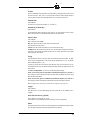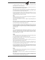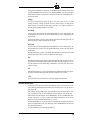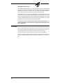
1
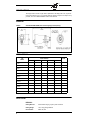
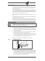
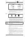
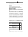
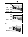
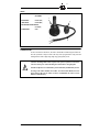
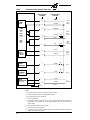
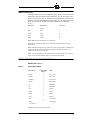
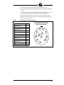
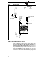
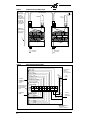
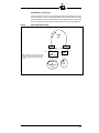
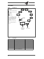
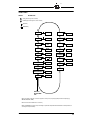
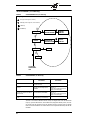
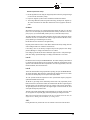
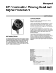
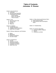
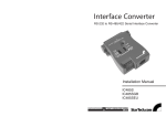
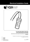
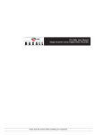
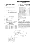
CU-95 November 2000 TYPE 95IR/95UV/95DS MODEL S1,S2 Integrated Flame Scanner with Internal Flame Relay Year 2000 Compliant in accordance with BSI document DISC PD2000-I:1998 DESCRIPTION The FIREYE InSight Type 95IR, 95UV, and 95DS flame scanners are micro-processor based flame scanners utilizing solid state infrared (IR) or ultraviolet (UV) or dual (IR and UV) sensors. The FIREYE InSight Type 95 flame scanners incorporate an internal flame relay with adjustable ON/OFF thresholds, thereby eliminating the need for a remote flame amplifier. The InSight scanners incorporate elements of the FIREYE Type 45FS1 and 45UVFS1 Signature Scanners™ as well as of the Type 45RM4 flame scanners to detect the presence or absence of a target flame in single or multi-burner applications. The InSight scanners measure the amplitude of the modulations (the flame “flicker”) that occur within the targeted flame. During the scanner set-up procedure, the modulation frequency that yields the best flame ON/OFF discrimination is selected. The appropriate modulation frequency and sensor gain is either manually selected (S1 models), or automatically selected with manual override capability (S2 models). The InSight 95IR, 95UV, and 95DS scanners are each available in two models differentiated by feature levels. The Standard Model S1 has three choices of modulation frequency, adjustable sensor gain, adjustable flame relay ON/OFF thresholds, 4-20 mA analog signal strength output, fault relay, and two selectable programmable files to store setpoints (for two different fuels or firing rates). The Expanded Model S2 adds automatic programming (AutoTune) with manual override capability, 21 choices of flame flicker frequency, a total of four selectable programmable files to store setpoints, plus adds remote communication capability via Fireye Windows 95/98/NT user software. All FIREYE InSight scanner models are powered by 24 Vdc, have a twelve-pin electrical quick-disconnect, and contain electronic self-checking (no mechanical shutter required). The scanners contain an eight character alpha-numeric LED display and a four (4) push-button keypad to enable the user to view operating parameters and select setpoints. 1 TABLE OF CONTENTS DESCRIPTION . . . . . . . . . . . . . . . . . . . . . . . . . . . . . . . . . . . . . . . 1 OPERATION . . . . . . . . . . . . . . . . . . . . . . . . . . . . . . . . . . . . . . . . 3 APPLICATION . . . . . . . . . . . . . . . . . . . . . . . . . . . . . . . . . . . . . . . 3 INSIGHT SCANNER FEATURES . . . . . . . . . . . . . . . . . . . . . . . . . . . . . 3 OPERATOR INTERFACE . . . . . . . . . . . . . . . . . . . . . . . . . . . . . . . . . 4 DIMENSIONS. . . . . . . . . . . . . . . . . . . . . . . . . . . . . . . . . . . . . . . . 4 AGENCY APPROVALS . . . . . . . . . . . . . . . . . . . . . . . . . . . . . . . . . . 4 SPECIFICATIONS . . . . . . . . . . . . . . . . . . . . . . . . . . . . . . . . . . . . . 4 INSTALLATION NOTES . . . . . . . . . . . . . . . . . . . . . . . . . . . . . . . . . . 6 INSTALLATION PROCEDURE . . . . . . . . . . . . . . . . . . . . . . . . . . . . . . 6 MECHANICAL ACCESSORIES . . . . . . . . . . . . . . . . . . . . . . . . . . . . . . 8 ELECTRICAL ACCESSORIES . . . . . . . . . . . . . . . . . . . . . . . . . . . . . . 8 SCANNER WIRING . . . . . . . . . . . . . . . . . . . . . . . . . . . . . . . . . . . 11 REMOTE FILE SELECTION. . . . . . . . . . . . . . . . . . . . . . . . . . . . . . . 13 ASSEMBLY INSTRUCTIONS, QUICK DISCONNECT KIT . . . . . . . . . . . . . . 13 WIRING FOR REMOTE COMMUNICATIONS . . . . . . . . . . . . . . . . . . . . . 16 GROUNDING AND SHIELDING TECHNIQUES . . . . . . . . . . . . . . . . . . . 19 PROGRAMMING THE InSight SCANNER . . . . . . . . . . . . . . . . . . . . . . . 20 INSIGHT MENU STRUCTURE . . . . . . . . . . . . . . . . . . . . . . . . . . . . . 20 THE STATUS MENU . . . . . . . . . . . . . . . . . . . . . . . . . . . . . . . . . . . 22 THE EDIT MENU . . . . . . . . . . . . . . . . . . . . . . . . . . . . . . . . . . . . . 25 FILE COPY INSTRUCTIONS . . . . . . . . . . . . . . . . . . . . . . . . . . . . . . 29 ERROR MESSAGES. . . . . . . . . . . . . . . . . . . . . . . . . . . . . . . . . . . 30 THE PRE-EDIT MENU (“S1” Models only) . . . . . . . . . . . . . . . . . . . . . . . 31 MANUAL SET-UP (“S1” Models only) . . . . . . . . . . . . . . . . . . . . . . . . . . 32 THE AUTOTUNE MENU (“S2” Models only) . . . . . . . . . . . . . . . . . . . . . . 34 ORDERING INFORMATION. . . . . . . . . . . . . . . . . . . . . . . . . . . . . . . 36 2 OPERATION The InSight scanners measure the amplitude of the modulations that occur within the targeted flame. During the scanner set-up procedure, the modulation frequency that yields the best flame ON: OFF discrimination is selected. The appropriate modulation frequency and sensor gain is either manually selected (S1models), or automatically selected with manual override capability (S2 models). With the appropriate modulation frequency selected, the flame relay’s ON and OFF thresholds are then entered. (This selection is set automatically with S2 models). The scanner’s 4-20 mA signal strength output is at minimum (4 mA) with a signal strength of “0”, and at maximum (20 mA) at a signal strength of 100. The FLAME RELAY is energized (and its normally open contacts close) when the signal strength is at or above the programmed flame ON threshold. The flame relay is de-energized when the signal strength is at or below the programmed flame OFF threshold. The flame relay contact circuit will also open upon a power interruption or the detection of an internal fault (see below). The FAULT RELAY is energized when the scanner is powered (24 vdc) and when the scanner had successfully passed all internal self-checking routines. The Fault relay is de-energized if there is a power interruption to the scanner or if the scanner has detected an internal fault. A normally open (fault relay) contact is wired in series with the flame relay contact (internally), and a normally closed contact is available for alarm indication. APPLICATION Type 95IR contains an infrared flame sensor, responding to infrared radiation from 700 to 1700 nanometers wavelength. This sensor is best suited to coal and oil applications. Type 95UV contains an ultraviolet flame sensor, responding to ultraviolet radiation from 295 to 320 nanometers wavelength. This sensor is best suited to gas applications. Type 95DS (Dual sensor) contains both the infrared and ultraviolet flame sensors described above. This sensor is best suited to multi-fuel applications. The Standard Model S1 is best suited to the many applications that do not require the level of sophistication, or the remote communications capability of the Expanded Model S2 (e.g. single burner boilers and furnaces, duct burners, etc.) The Expanded Model S2 is best suited to the applications that require the highest level of sophistication and flexibility (addition choices of modulation frequencies, and the time-saving AutoTune function), and remote communications capability (e.g. larger multi-burner boilers and furnaces). InSight SCANNER FEATURES Features Basic Models (S1) 95IR S1 Infrared Sensor 95UV S1 X Ultraviolet Sensor Expanded Models (S2) 95DS S1 95IR S2 X X X X 95UV S2 95DS S2 X X X Flame Relay X X X X X X Fault Relay X X X X X X 4-20 mA Output X X X X X X Modulation Frequency Selections 3 3 3 21 21 21 Memory Files 2 2 2 4 4 4 Communications X X X AutoTune X X X Pre-Edit X X X 3 OPERATOR INTERFACE The InSight scanners contain an eight character alphanumeric LED display and a four (4) push-button keypad to enable the user to view operating parameters and select setpoints. For complete set-up procedure, refer to the “PROGRAMMING” section in this document. DIMENSIONS FIGURE 1. TYPE 95IR/95UV/95DS SCANNER (shown with mounting flange, ordered separately) AGENCY APPROVALS PART NUMBER AGENCY APPROVALS CSA FM 95IRS1-1 X X 95UVS1-1 X X 95DSS1-1 X X 95IRS2-1 X X 95UVS2-1 X X 95DSS2-1 X X NOTES DIN-DVGW CE 95IRS1E-1 X X 95UVS1E-1 X X 95DSS1E-1 X X 95IRS2E-1 X X 95UVS2E-1 X X 95DSS2E-1 X X SPECIFICATIONS MECHANICAL: 4 Housing Material: Cast aluminum with gray polyester powder coat finish Housing Weight: 3 1bs (1.41kg), flange additional Environmental: NEMA 4X, IP66 Mounting: Requires one of two threaded mounting flanges, ordered separately (see below). Mounting Flange Kit: P/N 60-2692 1" NPT female pipe mount with 3/8" NPT female cooling air connection, includes 1" NPT x 3" long heat insulating nipple (P/N 35-127-1) P/N 60-2693 1" BSP female pipe mount with 3/8" BSP female cooling air connection, includes 1" BSP x 3"long heat insulating nipple (P/N 35-127-3) Mounting Flange Weight: 0.7 lbs (0.32kg) Cooling / Purge Air Requirements: Source: Clean, dry, cool Volume: 4 SCFM (113 l/min) at 3/8" threaded mounting flange, or 1 inch “Y” fitting, mounted on scanner sight pipe. Temperature near the upper limit of the scanner operating range and/or use with dirty/dusty fuels may require up to 15 SCFM (425 l/min). Pressure: Adequate to overcome furnace or windbox pressure Temperature Rating: -40° F to + 150°F (-40°C to +65°C) Humidity: 0% to 95% relative humidity, non-condensing ELECTRICAL: Input Power: 24 Vdc, +10%, -15% supply current 0.35 A, 8.5 VA Electrical Connection: 12-pin quarter-turn quick-disconnect Relay Output FLAME RELAY, SPST (N.O.) FAULT RELAY, SPST (N.C.) Contact Rating: Minimum: 10 mA @ 5 Vdc Maximum: 2 A @ 30 Vdc 2 A @ 50 Vac (CE approved models, see page 4) 2 A @ 240 Vac (FM & CSA models) Analog Output: 4-20 mA dc current, referenced to 24Vdc, maximum connected 1oad: 750 ohms Status Indication: Eight (8) character alpha-numeric LED display (scrolling capability) Operator Interface: Four (4) pushbutton style keys Cable Specification: P/N 59-497: Multi-core, 12 conductor (color coded), with foil wrap and overall braided shield Six #18 AWG and four #22 AWG conductors, plus one #22 AWG twisted pair Cable Jacket: Irradiated Modified Polyolefin (flame-retardant, low smoke, zero halogen) Nominal O.D. 0.41" (10.4 mm) Maximum O.D. 0.43" (10.9 mm) Maximum cable length 1000 feet (305 meters) 5 INSTALLATION NOTES The InSight flame scanners determine the presence or absence of flame by monitoring the frequency spectrum of the flame. The scanner should initially be mounted so that the primary combustion zone is within the scanner’s line of sight. The location and sighting instructions listed in the following sections are rough guidelines for the location of the scanner. The scanner provides feedback via its LED display to assist in the adjustment and proper alignment of the flame scanner. Refer to the setpoint procedures described in this bulletin. Note: An acceptable scanner location must ensure the following: Reliable main flame and/or ignitor flame detection at all air flow and furnace loads (ranges of fuel firing). Rejection of the ignitor flame if too short or in the wrong position to ignite the main flame reliably, thus prohibiting the delivery of fuel to the burner. Note: Due to the microprocessor based design of the InSight scanner, the heat insulating nipple (P/N 35-127-1 or 35-127-3) must be used to isolate the scanner from ground and to reduce conducted energy and noise. See Figure 7. The nipple is included in mounting flange kit P/N 60-2692, 60-2693. INSTALLATION PROCEDURE WARNING: Protective filtered lenses should be worn when viewing flame. Infrared and ultraviolet energy from the flame can be damaging to the eyes. 1. 2. 3. The best results are obtained when the scanner is aimed so that the scanner’s line of sight intersects the burner center at a slight angle (e.g. 5 degrees) and sees a maximum of the primary combustion zone, as shown in Figure 2. If only one scanner is used per burner, the line of sight should also intersect the igniting flame. For installations where separate scanners are used to monitor main and ignitor flames, the main flame scanner should be sighted so it does not detect the ignitor flame. The scanner should have an unrestricted view of flame as far as possible. Physical obstructions such as air register blades, interfering vanes, or other hardware should be cut away or notched so they do not fall within the scanner’s line of sight as shown in Figures 2 and 4. Note: Always check with the burner manufacturer before you trim the register blades. FIGURE 2. SINGLE BURNER SCANNER SIGHTING FLAME ENVELOPE AIR REGISTER BLADES SCANNER LINE OF SIGHT BURNER CENTER LINE BURNER THROAT BASE 4. 6 PRIMARY COMBUSTION ZONE Consideration must be given to burner secondary air rotation, some burners have clockwise (CW) air rotation and others have counterclockwise (CCW) air rotation. If combustion air enters the furnace with a rotational movement of sufficient velocity to deflect the ignitor flame in the direction of rotation, position the scanner 10 to 30 degrees downstream of the ignitor as shown in Figure 3 and close to the periphery of the burner throat (See Figure 2). FIGURE 3. SCANNER LOCATION VS. SECONDARY AIR ROTATION IGNITOR IGNITOR SCANNER SCANNER MAIN BURNER MAIN BURNER CCW ROTATION 5. CW ROTATION Having determined the approximate location for the sight pipe, cut a clearance hole for a 2 inch pipe through the burner plate. Look through the hole. If register vanes interfere with the desired line of sight, the interfering vane(s) should be trimmed to assure an unrestricted viewing path at all firing levels as indicated in Figures 2 and 4. Note: Always check with the burner manufacturer before you trim register vanes. FIGURE 4. FLAME MUST COMPLETELY COVER SIGHT OPENING NOT THIS 6. NOT THIS BUT THIS The preferred method for mounting surface mounted scanners requires the use of a swivel mount, Part No. 60-1664-3 (NPT), shown in Figures 5, 6 and 7. Center the swivel mount over the two inch hole in the burner plate and secure using three hexed cap screws (not provided). Install the sight pipe on the swivel mount. If a swivel is not used, insert the end of the sight pipe into the hole, align the hole to the desired viewing angle and tack weld (welding must be adequate to temporarily support the weight of the installed scanner). The sight pipe should be arranged to slant downward so that dirt and dust will not collect inside. CAUTION: Use no more than one foot of one inch diameter sight pipe. Increase the sight pipe diameter one inch for every additional foot of sight pipe length used to avoid restricting the scanner’s field of view. 7. 8. When a satisfactory sighting has been confirmed by operational testing, secure the swivel mount’s ball position in place by tightening the three hex head cap screws located on the swivel mount ring. For ease of use, the scanner should be installed on the sight pipe so the LED display can easily be read. Note: Operation of the LED display is independent of position. Note: Due to the microprocessor based design of the InSight scanner, the heat insulating nipple (P/N 35-127-1 or 35-127-3) must be used to isolate the scanner from ground and to reduce conducted energy and noise. See Figure 7. 9. The scanner lens must be kept free of contaminants (oil, ash, soot, dirt) and the scanner housing temperature must not exceed its maximum rating of 150° F (65° C). Excessive temperatures will shorten scanner life. Both requirements will be satisfied by a continuous injection of purge air at either the 3/8" housing inlet or the 1” “Y” connection ahead of the swivel mount as shown in Figures 5 and 6. Note: Internal scanner temperature is available via the LED display. See “Status Menu” under “Programming the Scanner.” 7 The scanner mounting may be made with provision for purge air through only the 3/8" opening as shown in Figure 7 or for purge air through either the 3/8" opening or the 1” “Y” connection as shown in Figure 6. In the latter arrangements, normally only one of the two connections is provided with purge air and the other connection is plugged. When a sealing union is used as shown in Figure 5, the 1" “Y” connection is used for the purge air and the 3/8" opening is plugged. It is good practice to use the sealing union (P/N 60-1199 with NPT threads) on all installations to insure against unwanted furnace pressures from damaging the scanner lens. Under normal conditions, with clean burning fuels and moderate ambient temperature conditions, purge air flow of approximately 4 SCFM (133l/min) is generally adequate. Up to 15 SCFM (425 l/min) may be required for fuels that produce high levels of ash or soot, or for hot environments to maintain the scanner’s internal temperature within specification. Flexible conduit should be used to wire the scanner from a grounded service box to the scanner. MECHANICAL ACCESSORIES Surface Mounting Flange (Required) P/N 60-2692 P/N 60-2693 1" NPT female pipe mount with 3/8" NPT female cooling air connection, includes locking ring and 1" NPT x 3" long heat insulating nipple (P/N 35-127-1). 1" BSP female pipe mount with 3/8" BSP female cooling air connection, includes locking ring and 1" BSP x 3" long heat insulating nipple (P/N 35-127-3). Swivel Mount (Optional) The scanner swivel mount, P/N 60-1664-3 (NPT) (see Figure 8, Item A), is used to adjust the scanner sighting angle after the scanner has been installed, The swivel mount is used as indicated in Figures 5, 6, and 7. Heat Insulating Nipple (Required) Heat Insulating nipple, P/N 35-127-1 (NPT), or P/N 35-127-3 (BSP) (see Figure 7, Item B), is used to prevent heat transfer from the hot sight pipe to the scanner head as well as electrically isolate the scanner from ground. The appropriate nipple (NPT or BSP) is shipped with the surface mounting flange. Sealing Union with Quartz Window (Optional) The sealing union, P/N 60-1199 (see Figure 8, Item B), is used whenever a coupling or a seal is required for scanner piping. The quartz window blocks furnace pressure, hot gases and soot from coming in contact with the scanner and contaminating the lens. The size is one inch U.S. standard taper pipe thread (Schedule 40, 1" - 11 1/2 NPT). When the sealing union is used, a 1 inch “Y” fitting must be used down stream of it for connection of a purge air supply (plug 3/8" opening). See Figure 5 for piping with the sealing union, Item D. ELECTRICAL ACCESSORIES Scanner Cable, P/N 59-497 Fireye recommends P/N 59-497 multi-core, 12 conductor (color coded), foil wrap and overall braided shield cable. This cable includes six #18 AWG and four #22 AWG conductors, plus one #22 AWG twisted pair. The cable jacket is Irradiated Modified Polyolefin (flame-retardant, low smoke, zero halogen) with a maximum diameter of 0.43" (10.9 mm). The maximum cable length is 1000 feet (305 meters) per scanner. This raw stock cable requires the Quick-Disconnect Kit described below. Refer to Figure 9 for color code and connection information. 8 Quick-Disconnect Kit, P/N 129-164 A twelve-pin (male) electrical connector is factory installed on the InSight scanners. Fireye offers the mating (female) connector for field installation onto the 59-497 cable. Refer to Quick-Disconnect assembly instructions. Scanner Cable with Factory installed Female Connector (P/N 59-497-XXX) Fireye offers the 59-497 12-conductor cable in pre-cut lengths with the female quick-disconnect factory installed. These assemblies are offered in lengths from 10 feet (3m) to 300 feet (91m) Wiring Harness Assembly, P/N 61-6944-XXX If remote communication is required (Model S2 only), and the distance between the InSight scanner and the control room exceeds 200 feet (61m), then a small junction box must be installed near each scanner. The two communications wires must be separated out of the twelve-conductor scanner cable at the junction box and wired independently in a multi-drop (“daisy-chain”) configuration to each scanner in the loop, and finally to the computer. The Fireye Wiring Harness Assembly, available in lengths from 3 to 30 feet (0.9 to 9.1m), provides a convenient method to accomplish this. On one end, the harness has a female quick-disconnect to connect to the InSight scanner. Fireye twelve-conductor cable, P/N 59-497 is factory wired to the quick-disconnect, run through flexible conduit and connected to a terminal strip within a junction box at the other end of the harness. The terminal strip accepts up to 14 AWG wires and uses push-type cage clamp connectors for quick and secure connections. From the junction box, the installer would connect all but two wires of a length of Fireye 59-497 twelve-conductor cable that is run to the burner management system. The two communications wires originating from the scanner would be connected from one junction box to the next, and finally to the computer using a two-conductor communications cable (Belden #8761, 22 AWG or equal). 24 Volt DC Power Supplies Fireye offers two DIN rail mounted 24 vdc power supplies for use with the InSight Integrated flame scanner. Model 60-2685-2 (2 amp) can power up to five InSight scanners, model 60-2685-4 (4 amp) can power up to ten Insight scanners ( see note 1). PART NUMBER DESCRIPTION NOTES 60-2685-2 24 VDC Switching Power Supply, 50W, 100-240 vac 50/60 Hz. input, 2.1 A output at 24 vdc Dimensions: 3.2"(82mm) high x 3.5" (90mm) wide x 3.6"(91mm) deep 1,2 60-2685-4 24 VDC Switching Power Supply, 100W, 120 / 240 vac 50/60 Hz. input, 4.2 A output at 24 vdc Dimensions: 3.2"(82mm) high x 5.7" (145mm) wide x 3.6"(91mm) deep 1,2 60-2539-12 DIN mounting rail, 12" (305mm)long 2 60-2539-24 DIN mounting rail, 24" (610mm)long 2 60-2539-36 DIN mounting rail, 36" (914mm)long 2 Notes: 1. Rated output is when power supply is vertically mounted, and with an ambient temperature of 122F (50C) maximum. When supply is mounted vertically, at 140F (60C) the output is de-rated 25%. 2. When mounted in a row, allow at least 0.79" (20mm) between adjacent power supplies. 9 FIGURE 5. PART NUMBER 23.8” (605mm) A. SWIVEL MOUNT 60-1664-3 (NPT) 60-1664-4 (BSP) B. 1" WYE 35-200 (NPT) C. 1” CLOSE NIPPLE 35-201 (NPT) C E F D. SEALING UNION W/QUARTZ WINDOW 60-1199 (NPT) E. HEAT INSULATING NIPPLE 35-127-1 (NPT) 35-127-3 (BSP) F. 3/8" PLUG 35-202 (NPT) G. SURFACE MOUNTING FLANGE (includes item E) 60-2692 (1”NPT) 60-2693 (1”BSP) A B D G FIGURE 6. PART NUMBER A. SWIVEL MOUNT 60-1664-3 (NPT) 60-1664-4 (BSP) B. 1" WYE 35-200 (NPT) C. HEAT INSULATING NIPPLE 35-127-1 (NPT) 35-127-3 (BSP) D. 3/8" PLUG 35-202 (NPT) E. SURFACE MOUNTING FLANGE (includes item C) 60-2692 (1”NPT) 60-2693 (1”BSP) 20.6” (523mm) D A B C E FIGURE 7. 15.3” (389mm) PART NUMBER B A. SWIVEL MOUNT 60-1664-3 (NPT) 60-1664-4 (BSP) B. HEAT INSULATING NIPPLE 35-127-1 (NPT) 35-127-3 (BSP) C. 3/8" THREADED OPENING D. SURFACE MOUNTING FLANGE (includes item B) 10 60-2692 (1”NPT) 60-2693 (1”BSP) A D C FIGURE 8. PART NUMBER A A. SWIVEL MOUNT 60-1664-3 (NPT) SWIVEL MOUNT 60-1664-4 (BSP) B B. SEALING UNION W/QUARTZ WINDOW 60-1199 (NPT) C. SCANNER CABLE 59-497 C SCANNER WIRING To reduce electrical noise interference, the scanner cable should be installed in rigid or flexible conduit. Take precautions to keep the scanner cable away from any high inductive wiring associated with high inductive loads or high voltage, high energy spark ignition systems. CAUTION: The InSight flame scanner requires 24 Vdc power for operation. Connection to a 24 Vac or 120 Vac power source will damage the scanner. Refer to wiring diagrams. External 2.0 Amp fuses are recommended to protect Flame Relay and Fault Relay contacts All wiring to the scanner should be rated at 90°C. For runs less than 1000 feet, the use of Fireye Scanner Cable, Part No. 59-497, (12 wire) is recommended. For runs in excess of 1000 feet, consult the factory. 11 FIGURE 9. WIRING DIAGRAM, INSIGHT INTEGRATED FLAME SCANNER TYPE 95IR/95UV/95DS QUICK-DISCONNECT PIN NUMBER (+) INPUT POWER 24VDC (-) A FIREYE CABLE 59-497 COLOR CODE B WHITE/BLUE C WHITE/BLACK FLAME RELAY (+) BLACK/RED (-) (Note 1) FAULT RELAY D WHITE/RED E RED (Note 2) FUSE FAULT RELAY (Note 2) (+) 4-20mA OUTPUT Referenced to Common (-) F PINK G VIOLET H FUSE 24 VDC INPUT POWER TO BMS INPUT (Notes 6, 7) TO BMS INPUT (Notes 6, 7) TO BMS METER (Note 6) GREY/RED SW1 REMOTE FILE SELECT 1 J BLUE/RED REMOTE FILE SELECT 2 K YELLOW L BROWN M ORANGE (Note 5) SW2 (Note 5) (Model S2 only) A REMOTE COMMUNICATIONS B (Model S2 only) TO COMPUTER (Notes 3, 4) (Note 8) Notes: 1. 2. 3. 4. 5. 6. 7. 8. 12 Flame relay contacts are shown in de-energized (no flame) condition. Fault relay contacts are shown in de-energized (fault) condition. Brown and orange wires are a twisted pair. Cable shield not shown. With Remote File Select programmed as “LINE”, external switches SW1/SW2 (not furnished) will select between two (S1 Models) or four (S2 Models) internal memory files, when connected to 24Vdc(-) supply. BMS = Burner Management System (by others). External 2.0 Amp fuses recommended. A ground screw is provided on the scanner end plate. An external ground wire must be installed if line voltage is applied to the relay contacts. REMOTE FILE SELECTION The InSight scanners have more than one internal memory file. The user has the option of storing different scanner setpoints for different operating conditions (e.g. Gas / Oil, Pilot / Main, Low Fire / High Fire, etc.) in these files. The “S1” models have two programmable files (A & B), and “S2” models have four (A,B,C, & D). With RFS selected as “LINE”, one or two external switches (supplied by user) will select between the files when the RFS1 or RFS2 wires are connected to 24 vdc (-). RFS1 (Blue) RFS2 (Yellow) File Selected (Note 1) Open Open A Closed Open B Open Closed C Closed Closed D Note 1: RFS2 function is available in the “S2” models only. Note 2: The user may also select RFS as “KEY” which will allow manual file selection at the scanner keypad. Note 3: With FM & CSA approved “S2” models, the user may also select RFS as “COMM” which will allow manual selection at a remote computer running Fireye software. This feature is not available with CE approved “S2E” models. Note 4: Fireye recommends the use of shielded cable for the two remote file select switches (or relays). The switch contacts should be rated for low current operation (3mA dc). ASSEMBLY INSTRUCTIONS, QUICK DISCONNECT KIT P/N 129-164 ASSEMBLY (Refer to Figure 11) FIGURE 10. QUICK DISCONNECT TERMINAL 59-497 Cable Color Pin Number of Quick Disconnect Function Black/Red A Power (+) 24 Vdc White/Blue B Power (-) 24 Vdc White /Black C Flame Relay (N.O.) White/Red D Flame Relay (N.O.) Red E Fault Relay (N.C.) Pink F Fault Relay (N.C.) Violet G 4-20 mA (+) Grey/Red H 4-20 mA (-) Blue/Red J File Select 1 *Yellow K File Select 2 *Brown L Communications A *Orange M Communications B * “S2” models only Note: Brown and orange wires are a twisted pair. 13 FIGURE 11. FOR EASE OF CONNECTOR ASSEMBLY, INSTALL ON END SHOWN COLOR CODE: RD PK BN VT BK = BLACK RD = RED WT = WHITE PK = PINK VT = VIOLET GY = GREY BU = BLUE YL = YELLOW BN = BROWN OR = ORANGE WT/RD WT/BK OR WT/BU GY/RD BK/RD BU/RD FIGURE 12. YL For ease of assembly, install the 129-164 connector on the 59-497 cable end where the 3 white wires are clockwise to the red wire. CONNECTOR ASSEMBLY INSTRUCTIONS .87 ± .04 (22.1 ±1) BRAID .15 - .18 (3.8 - 4.6) 1.75 ± .04 (44.5 ±1) Inches (mm) CLAMP NUT HOUSING CABLE SEAL GROUNDING RING SCANNER CABLE 59-497 SUPPORT SLEEVE O-RING CABLE GRIP COUPLING NUT FEMALE CONTACTS PLUG CONNECTOR CONNECTOR ASSEMBLY STEPS 1. 2. 3. 4. 14 Select 59-497 cable end with the wire color orientation as shown in Figure 10. Slide items along the cable as shown, including coupling nut and O-ring (discard the black thread protector and orange grommet from plug connector). Strip cable connector end in accordance with Figure 11. Slide braid back and forth to loosen, then fold braid back over cable jacket. Cut and discard foil tape. Solder the wires to the contacts. 5. 6. 7. Slide contacts into plug connector per wiring table until contacts lock in place. Slide coupling nut up against plug connector flange and slide O-ring into groove on plug connector body. Slide support sleeve back over braid and drain wire then place braid over spring elements of support sleeve. Clamp braid and drain wire by snapping on the metal grounding ring. Screw housing onto the plug connector. Torque to 27 lb-in ± .25 lb-in, (3.05N-m ± 0.03 N-m). Assemble cable seal and cable grip to the housing, screw clamp nut onto housing and tighten to 27 lb-in ± .25 lb-in, (3.05N-m ± 0.03 N-m). FIGURE 13. WIRING TABLE AND PLUG CONNECTOR PIN LOCATION WIRE PIN BLACK/RED, #18 AWG A WHITE/BLUE, #18 AWG B WHITE/BLACK, #18 AWG C WHITE/RED, #18 AWG D RED, #18 AWG E PINK, #18 AWG F VIOLET, #22 AWG G GREY/RED, #22 AWG H BLUE/RED, #22 AWG J YELLOW, #22 AWG K BROWN, #22 AWG TWISTED L ORANGE, #22 AWG TWISTED M PLUG CONNECTOR PIN LOCATION (VIEWED FROM PIN INSERTION SIDE) A J B K H C L M G F D E 15 FIGURE 14. WIRING HARNESS ASSEMBLY HARNESS ASSEMBLY NO Part No. 61-6944-003 61-6944-010 61-6944-015 61-6944-020 61-6944-030 Length 3 ft. 10 ft. 15 ft. 20 ft. 30 ft. Safety Ground Ground Screw Scanner Quick Disconnect Connector and Flexible Metal Conduit Belden 8761 for communication to other scanners 59-497 CABLE (ordered separately) TO BURNER MANAGEMENT SYSTEM OUT IN EMI CONNECTOR (not included) For FIREYE 59-497 cable Housing Connected to Earth Ground 1 2 3 4 5 6 7 8 9 10 11 12 Prewired by Factory WIRING FOR REMOTE COMMUNICATIONS (“S2” models only) Remote communications with the InSight scanner uses an RS485 Interface to carry the communication signals. An IBM compatible PC running Fireye software is required to communicate with the flame scanners. The wiring configuration for remote communications is dependent on the distance between the scanner and amplifier. For distances less than 200 feet, wire the Fireye cable P/N 59-497 to the female quick disconnect in the manner previously described, and run the cable directly back to the burner management system. For wiring distances greater than 200 feet, remote communications requires wiring a twisted, shielded pair of wires in a “multi-drop” wiring configuration, and then use a terminating resistor at the scanner located farthest from the communication source. See “Using Fireye Wiring Harness.” 16 Note: The maximum distance for the communication wiring for all associated InSight scanners is 4,000 feet. The maximum number of scanners connected to the communication link is 32 scanners. Exceeding this total wiring length or number of scanners requires the installation of bi-directional repeaters or amplifiers. Consult factory for additional information. Using Fireye Wiring Harness (P/N 61-6944 -003, -010, -015, -020, -030). To provide an easy method to wire the InSight scanners in a “Multi-drop” wiring configuration for remote communications, Fireye offers a wiring harness in 5 different lengths (3, 10, 15, 20 and 30 ft.). The harness has a pre-wired female quick disconnect to plug into the quick disconnect on the scanner. The other end of the wiring harness has a conduit box with a 16 connector terminal strip. Twelve (12) connectors are pre-wired to the female quick disconnect. Cable 59-497 Cable Belden 8761 Belden 8761 Color Function Wire cable Black/Red Power (+) 24 VDC Wiring Harness 1 White/Blue Power (-) 24 VDC 2 White /Black Flame Relay (N.O.) 3 White/Red Flame Relay (N.O.) 4 Red Fault Relay (N.C.) 5 Pink Fault Relay (N.C.) 6 Violet 4-20 mA (+) 7 Grey/Red 4-20 mA (-) 8 Blue/Red File Select 1 9 Yellow File Select 2 10 Brown Communications A 11 Orange Communications B 12 Black RS485 COM A 11 Clear RS485 COM B 12 To next flame scanner Black RS485 COM A 11 RS485 COM B 12 To previous flame scanner (or IC485 converter) Clear Back to Control Room (Burner Management System) 17 FIGURE 15. SUGGESTED WIRING FOR COMMUNICATIONS RS485 communication; For each individual wiring run, connect shields together. Connect one end of the shield circuit to ground. Tape and isolate other end. See next page for more detail. RS485 COMMUNICATIONS 59-497 to Control Room TO NEXT WIRING HARNESS 59-497 to Control Room BELDEN #8761 (Twisted, shielded pair) to previous wiring harness. 1 2 3 4 5 6 7 8 9 10 11 12 1 Flex Conduit to Scanner FIGURE 16. 2 3 4 5 6 7 8 9 10 11 12 Flex Conduit to Scanner WIRING DIAGRAM FOR WIRING HARNESS COM B — ORANGE COM A — BROWN 1. CONNECT SHIELDS TOGETHER. 2. TAPE SHIELD AT LAST WIRING HARNESS RFS2— YELLOW RFS1— BLUE/RED 4-20mA (-) — GREY/RED CLEAR 4-20mA (+) — VIOLET FAULT RELAY (N.C.) — PINK TO FLAME SCANNER (prewired by factory) CONNECT SCANNER SHIELDS TOGETHER AND GROUND AT BURNER MANAGEMENT SYSTEM TO CONTROL ROOM TO NEXT SCANNER COM B COM A BLACK FAULT RELAY (C) — RED FLAME RELAY (N.O.) —WHITE/RED FLAME RELAY (C) WHITE/BLACK (-)24VDC — WHITE/BLUE (+) 24VDC — BLACK/RED BELDEN 8761 59-497 1 2 BLACK/RED WHITE/BLUE WHITE/BLACK WHITE/RED RED PINK VIOLET GREY/RED BLUE/RED YELLOW 3 4 5 6 7 8 9 10 11 12 CLEAR COM B TO PREVIOUS SCANNER, OR EC485 CONVERTER. BLACK COM A 1. CONNECT SHIELDS TOGETHER 2. CONNECT SHIELD TO EARTH GROUND AT ORIGIN. (FIRST HARNESS OR PC) 18 FIGURE 17. WIRING FOR REMOTE COMMUNICATIONS 1. WHEN THE DISTANCE FROM SCANNER TO CONTROL ROOM< 200 FEET. 59-497 CABLE 59-497 CABLE 59-497 CABLE BELDEN 8761 BURNER MANAGEMENT SYSTEM BELDEN 8761 BURNER MANAGEMENT SYSTEM PC WITH FIREYE SOFTWARE BELDEN 8761 RS485-RS232 CONVERTER, P/N IC485 BURNER MANAGEMENT SYSTEM 2. WHEN THE DISTANCE FROM SCANNER TO CONTROL ROOM >200 FEET. BELDEN 8761 BELDEN 8761 61-6944 WIRING HARNESS 59-497 CABLE 59-497 CABLE BURNER MANAGEMENT SYSTEM BURNER MANAGEMENT SYSTEM BELDEN 8761 RS485 COM A COM B 59-497 CABLE RS485-RS232 CONVERTER, P/N IC485 PC WITH FIREYE SOFTWARE BURNER MANAGEMENT SYSTEM GROUNDING AND SHIELDING TECHNIQUES FOR USE ON SCANNERS OR SCANNER CABLE LOCATED WITHIN 12" OF A HIGH ENERGY OR HIGH VOLTAGE SOURCE. 1. 2. 3. 4. 5. 6. Connect a safety ground to scanner housing (Figure 13). The scanner and scanner cable (preferably within flexible conduit) MUST be located at least 12" from the ignition source. Run a ground wire from the ignition transformer chassis to the ignitor assembly. Replace all frayed, cracked, or dirty (oily) ignition wire. Ignition wire must be in good working condition. Electrically isolate the scanner from the burner using a heat insulating nipple provided with the surface mounting flange. Cooling/Purge Air must be electrically isolated from the scanner (e.g. isolated short rubber hose). SCANNER TO CONTROL ROOM SHIELDING TECHNIQUES Scanner with scanner cable (59-497) wired directly back to burner management system. See below for remote communications. Attach drain wire to scanner quick disconnect as described. Use heat insulating nipple on scanner. Connect drain wire of 59-497 to earth ground at power supply. REMOTE COMMUNICATIONS: LESS THAN 200 FEET Scanner with scanner cable (59-497) wired directly back to control room. Attach drain wire to scanner quick disconnect as described. Use heat insulating nipple on scanner. Connect drain wire of 59-497 to earth ground at power supply. REMOTE COMMUNICATIONS: GREATER THAN 200 FEET RS485 communications for scanners wired in a multidrop configuration (Belden 8761) using wiring harness or junction box. Attach drain wire to scanner quick disconnect as described. Use heat insulating nipple on scanner. Connect drain wire of 59-497 to earth ground at power supply. Twist together and tape (to electrically isolate) drain shields from Belden 8761 cables inside each wiring harness or junction box. Connect shield drain to earth ground at RS485 source (e.g. IBM computer). 19 PROGRAMMING THE INSIGHT SCANNER Keypad/Display: The InSight flame scanner uses an eight (8) character alphanumeric LED Display and four (4)pushbuttons to review and program the various setpoints and operating parameters. The functions of the pushbuttons are: UP/DOWN The UP and DOWN buttons are used to scroll through the scanner menus. When in the EDIT menu, after selecting a setpoint to edit, (see SELECT button), the UP and DOWN buttons are used to change that setpoint. SELECT When in the EDIT menu, the UP / DOWN buttons are used to display the setpoints. Depressing the SELECT button displays the stored value of the setpoint, allowing it to be changed. PROGRAM The PROGRAM button saves a change made to a setpoint. It is also used to execute the Auto Tune function (“S2” Models only) or Pre-Edit function (“S1” Models only). INSIGHT MENU STRUCTURE For ease of operation, the InSight scanner contains three menus (or loops) accessed via the keypad and viewed on the scanner’s display. STATUS MENU The Status menu is the default display, and appears as soon as power is applied. Use the UP and DOWN buttons to scroll through the menu and view the current operating status. No operating parameters can be changed from the Status menu. To change any setpoint, you must enter a four digit password then enter the Edit, or Pre-Edit (“S1”) or AutoTune (“S2”) menus. EDIT MENU The Edit Menu contains all the user-selected setpoints for the InSight scanner. The Edit menu is entered from the Status menu after first entering a four-digit password. In the Edit menu, the user is allowed to change the setpoints to optimize the scanner performance. PRE-EDIT MENU (“S1” Models only) From the Pre-Edit menu, the user views the flame signal intensity and physically aims the scanner for optimum signal. The user then commands the scanner to set an appropriate internal front-end gain (FEG) level. As with the Edit menu, the Pre-Edit menu is entered from the Status menu after first entering a four-digit password. 20 AUTOTUNE MENU (“S2” Models Only) From the AutoTune menu, the user views the flame signal intensity and physically aims the scanner for optimum signal.The user then commands the InSight scanner to analyze the flame ON and OFF (background radiation) conditions, and automatically select the optimum setpoints. As with the Edit menu, the AutoTune menu is entered from the Status menu after first entering a four-digit password. FIGURE 18. INSIGHT SCANNER MENU STRUCTURE STATUS LOOP FQ O Note 1 NOTE 1: If the password is not entered, access to the EDIT, PRE-EDIT and AUTO TUNE loops are denied. Pressing the (▲) UP KEY advances the display directly to “FQ O”. PASSWORD AUTOTUNE (“S2”) OR PRE-EDIT (“S1”) EDIT AUTOTUNE (“S2”) OR PRE-EDIT (“S1”) LOOP EDIT LOOP Note 1 21 THE STATUS MENU FIGURE 19. STATUS MENU LOOP FILE A Keypad Legend NOTE 3 iO uO UP Key (Scrolls through menu, clockwise) COMM 0 T=46C NOTE 4 DOWN Key (Scrolls through menu, counter clockwise) SELECT Key SOFTWARE REVISION FLAME OFF PROGRAM Key NOTE 1: If the password is not entered, access to the EDIT, PRE-EDIT and AUTO TUNE loops are denied. Pressing the (▲) UP KEY advances the display directly to “FQ O”. MAX 51C START HERE FQ 0 NOTE 2: Refer to PASSWORD section for further details. NOTE 3: Dual sensor model shown (IR & UV). PASSWORD AUTOTUNE (“S2”) OR PRE-EDIT (“S1”) NOTE 4: Communications available in “S2” models only. TO PRE-EDIT (“S1”) OR AUTOTUNE (“S2”) MENU LOOP FIGURE 20. NOTES 1 & 2 NOTE 1 EDIT TO EDIT MENU LOOP THE STATUS MENU TEXT DISPLAYED DESCRIPTION POSSIBLE VALUES FQ 0 Flame Quality (scanner output) FLAME OFF Flame Relay status ON, OFF T= 46C Present Scanner temperature +32°F to 212°F (0°C to 100°C) File A Scanner file in operation A,B,C,D i0 u0 Signal strength, IR and UV (dual sensor models) 0-999 COMM 0 Communication address (“S2” models only) 0-127 SOFTWARE REVISION Scanner software revision MAX 46C Scanner Temperature, stored maximum -40° F to 185°F (-40°C to 85° C) PASSWORD A Password is required to enter the EDIT, PRE-EDIT or AutoTune menus. See PASSWORD section. 0000-9999 22 0-100 Flame Quality The “Flame Quality” number can range from 0 to 100. It represents the scanner’s 4-20 mA analog flame signal strength OUTPUT (in percent), and is the scale by which the internal Flame Relay ON and OFF thresholds are set. The “Flame Quality” number is determined by the input of the IR and / or UV sensor, (in dual sensor models it is the sum of the two). This sensor signal strength value can be viewed in the Status menu as “Signal Strength”, see description below. For clarity, the “Flame Quality” number is capped at 100, while under certain firing conditions the IR or UV “signal strength” (or their sum) may normally exceed 100 (maximum of 999). In normal burner operation after the scanner has been properly setup, “FQ 100” will be displayed with occasional movement depending on the stability of the flame. Flame ON/Off This item refers to the energized / de-energized status of the internal Flame relay. “Flame ON” is displayed when the flame quality rises above the relay “On Threshold” set in the Edit menu. When the flame quality drops below the relay “Off Threshold”, “Flame OFF” will be displayed. Temperature The scanner’s present temperature in degrees, expressed in either Fahrenheit or Centigrade depending on which was selected in the Edit menu. File Selected The current running file is displayed. Choices are files “A, B” for S1 Models, and files “A,B,C,D” for S2 Models. Signal Strength The Signal Strength number represents the intensity of the “flame flicker”, as sensed by the IR and / or UV sensor(s), and is a function of the individual sensor “Gain” and “Bandpass” (flicker frequency) settings. The Signal Strength number is related to the Flame Quality number (see Signal Strength expanded description below). Comm Address (“S2” Models Only) This number refers to the remote communications address of the scanner. The address can range from 0 to 127, as selected in the Edit menu. No two scanners in a communications loop should have the same address. Software Revision This displays the internal software revision. Maximum Temperature This displays the highest scanner temperature recorded. Password A four-digit Password is required to enter the EDIT and AUTOTUNE menus. If a Password is not entered, pressing the UP key will advance directly to the “Flame Quality” display, pressing the DOWN key will return to the “Maximum Temperature” display. To enter the EDIT or AUTOTUNE menus, you must enter the four-digit Password. The following example is for the factory installed password of 0205: 1. With “PASSWORD” displayed, depress the SELECT key. “0xxx” will be displayed, the first digit (“0”) is adjustable. (If the factory password was changed, use the UP/DOWN keys to select the appropriate first digit). 23 2. 3. 4. 5. With the first digit selected (e.g. “0xxx”) depress the PROGRAM key. “00xx” will be displayed, the second digit (“0”) is adjustable. Depress the UP key twice to display “2”. (If the factory password was changed, use the UP/DOWN keys to select the appropriate second digit). With the second digit selected (e.g. “02xx”) depress the PROGRAM key. “020x” will be displayed, the third digit (“0”) is adjustable. (If the factory password was changed, use the UP/ DOWN keys to select the appropriate third digit). With the third digit selected (e.g. “020x”) depress the PROGRAM key. “0200” will be displayed, the fourth digit (“0”) is adjustable. Depress the UP key five times to display “5”. (If the factory password was changed, use the UP/DOWN keys to select the appropriate fourth digit). With all four digits selected (e.g. “0205”) depress the PROGRAM key. If the Password was not entered correctly, the display will read “Wrong Password”. Depress the SELECT key to re-enter the password. If the Password was entered correctly, the display will read “Valid Password. Press SELECT to change password”. If you wish to change the password at this time, see the “Change Password” section below. Otherwise, depress the UP key to advance to the EDIT and AUTOTUNE menus. Entering the correct Password allows the user 20 minute access to the EDIT and AUTOTUNE menus. Changing any parameter will re-start this 20 minute time-out period. Change Password The user may change the password (the factory set password is “0205”) to any four-digit code desired. To change the password, you first enter the current password as described above. When the display reads “Valid Password. Press SELECT to change password”, press the SELECT key and “0xxx NEW” is displayed, the first digit (“0”) is adjustable. For example, enter a NEW password of “1357”. Use the UP/DOWN key and the PROGRAM key (as described in the above section) to enter the new password. When complete, in this example the display will now read “New password 1357”. Depress the UP/DOWN keys to return to the menu loops. Signal Strength & Flame Quality (FQ), Expanded Description Single sensor models (Type 95IR, 95UV): The value of Signal Strength is the same as the “Flame Quality” number except that the Signal Strength value is allowed to exceed 100 (maximum of 999) while “Flame Quality” is capped at 100. Dual sensor models (Type 95DS): This screen shows the individual sensor’s contribution to the Flame Quality number. Each value is preceded by the corresponding lower case letter indicating whether it is the IR (i) or UV (u) sensor. Under most firing conditions, the sum of these individual values will exceed 100 (maximum of 999). Important Note: The Flame Quality number is the Flame Signal number, but is capped at 100. In dual sensor (95DS) models, it is the sum of the IR + UV Signal Strength numbers, but the sum is capped at 100. Example 1 (Single Sensor Model 95IR, infrared): If “I 80” is displayed as signal strength, you would see a Flame Quality number of “FQ 80” displayed on the Flame Quality screen. If “I 120” is displayed as signal strength, you would see a Flame Quality number of “FQ 100” on the Flame Quality screen, because Flame Quality is capped at 100. Example 2 (Dual Sensor Model 95DS): If “i80 u15” is displayed as signal strength, you would see a Flame Quality number (the IR and UV signal sum) of “FQ 95” displayed on the Flame Quality screen. If “i70 u 40” is displayed as signal strength, although the sum is 110, you would see a Flame Quality number of “FQ 100” on the Flame Quality screen, because Flame Quality is capped at 100. 24 THE EDIT MENU FIGURE 21. EDIT MENU LOOP UP Key (Scrolls through menu, clockwise) DOWN Key (Scrolls through menu, counter clockwise) SELECT Key PROGRAM Key P IRR HIGH UV BAND u70/0 IR GAIN iG1/0 UV GAIN uG1/0 IR BAND i 70/0 UV RANGE SENSORS UV & IR ON THRESHOLD ONT 40 LANGUAGE ENGLISH OFF THRESHOLD OFFT 20 IR RANGE FILE COPY REMOTE FILE SELECT COMM ADDRESS A RFS KEY UVR HIGH FFRT FFRT 1 OTD OTD 1 COMM O --EXIT-- TEMPERATURE SCALE FILE SELECT SCALE C FILE A FROM “EDIT” ON STATUS MENU LOOP NOTE 1: Dual Scanner model shown. If scanner is single sensor model (IR of UV) only the appropriate parameter will be displayed (e.g. SENSORS, BAND, GAIN, RANGE). NOTE 2: Communications available with “S2” models only. NOTE 3: The PROGRAM Key is used to accept a value change for all parameters except IR/UV Gain and IR/UV Band. For these parameters, the value change is accepted immediately. 25 FIGURE 22. THE EDIT MENU TEXT DISPLAYED DEPRESS ‘SELECT’ KEY, TEXT DISPLAYED POSSIBLE VALUES (UP/DOWN KEYS) File Select FILE A “S1” models: A.B “S2” models: A.B, C, D Temperature Scale Scale C C, F Comm address COMM 0 0-127 Remote File Select RFS KEY “S1” models: KEY, LINE “S2” models: KEY, LINE, COMM File Copy A-> (See File Copy Section) Language English English Sensors UV + IR (Dual Sensor Models Only) UV + IR, IR Only, UV Only IR Band i70/ 0 (IR Frequency selected/Signal strength) “S1” Models: 23, 70, 117 “S2” Models: 23, 31, 39, 46, 54, 62, 70, 78, 85, 93, 101, 109, 117, 125, 132, 140, 148, 156, 164, 171, 179 Hz IR Gain iG1 / 0 (IR Gain selected/ Signal strength) 1 - 31 IR Range IRR HIGH HIGH, LOW UV Band u70/ 0 (UV Frequency selected/Signal strength) “S1” Models: 23, 70, 117 “S2” Models: 23, 31, 39, 46, 54, 62, 70, 78, 85, 93, 101, 109, 117, 125, 132, 140, 148, 156, 164, 171, 179 Hz UV Gain uG1 / 0 (UV Gain selected/ Signal strength) 1 - 31 UV Range UVR HIGH HIGH, LOW On Threshold ONT 40 5 - 100 Off Threshold OFFT 20 0 - 95 FFRT FFRT 1 1, 2, 3, 4, 5, 6 seconds OTD OTD 1 1, 2, 3, 4, 5, 6 seconds --EXIT-- Edit (Returns you to STATUS loop) THE EDIT MENU The values of the menu choices are viewed by pressing the SELECT button. (To exit the viewed value without changing it, press the SELECT button again). To change a value, press the UP / DOWN keys until the desired value is displayed. Depress the PROGRAM button. The display will scroll “Parameter saved”, then automatically de-select the menu choice as if the SELECT button had been pressed. See important note below. IMPORTANT NOTE: In order to immediately see the effect of a setpoint change upon the “Signal Strength” number, some parameter values are changed and saved immediately via the UP / DOWN keys, and do not require depressing the PROGRAM key. These parameters include IR Band, UV Band, IR Gain, and UV Gain. The “Signal Strength” number is displayed to the right of the parameter value on the same screen, providing the user instantaneous feedback. Note: You may only Edit the File that the scanner is currently running. For example, to Edit file “B”, you must be currently running file “B”. (See File Select section below). Exceptions: A change made to the Temperature Scale, Comm Address, Remote File Select, and Language parameters, can be made in any file and the new values will be automatically saved to all files. 26 File Select The user can manually choose which file to run (and to Edit) by selecting this menu choice provided the Remote File Select “KEY” choice is selected (see below). If the user wants to Edit the contents of a file, they must first select and run that particular file. (See “exceptions” in note above). Temperature Scale (Affects all files) The scale may be selected to be Fahrenheit “F”, or Celsius “C”. Comm Address (“S2” Models Only) (Affects all files) The communications address selected may range from 0 to 127. Each scanner must have a unique address. No two scanners in a communications loop can have the same address. Remote File Select (Affects all files) Choices are KEY, LINE, COMM* KEY allows the file selection to be made only at the scanner keypad (See File Select menu choice above). LINE allows the file selection to be made only via an external switch or relay. COMM allows the file selection to be made only via an external computer running Fireye Software. This feature is only available with FM & CSA approved “S2” models. This feature is not available with CE approved “S2E” models. FileCopy This function allows the user to copy the contents of one internal scanner file to another. “S1” Models have two user configurable files, “A,B”, plus two factory configured files, “F1, F2”. “S2” Models add two additional user files, “C, D”. You may copy from any file to a user file. You are not allowed to copy from a user file to a factory file. You must first enter the source file, then the destination file (Refer to FileCopy instructions at the end of this section). The Factory Configured Files (“F1” and “F2”) contain factory default settings. In File “F1”, the sensor gain is set at maximum (31) and the flicker frequency is set at 23 Hz. At these settings the scanner will respond to flame but will not likely discriminate between the target flame and other nearby flames. In File “F2”, the sensor gain is set at minimum (1) and the flicker frequency is set at 70 Hz. At these settings the scanner will not likely respond to flame until the scanner gain is increased. Note: As shipped, all user files (A,B,C,D) contain the same setpoints as factory file “F2”. Language (Affects all files) This allows the user to select which language the menu system will use. The available choice is “English”. Sensors (dual sensor units only, Type 95DS) Choices include: UV only, IR only, or UV+IR This parameter is used to manually select which sensor(s) are used in a particular file. IR Band The display is broken into two halves. The left side displays the selected IR flicker frequency (bandpass). The right side displays the signal strength attributed to the IR sensor. 27 For example with a model “S2” scanner, “i 23 / 80” indicates that 23Hz is selected and the current signal strength is 80 (as viewed in the Status loop). Frequency choices range from 23Hz to 179Hz (“S2” models), or from 23Hz, 70Hz, 117Hz (“S1” models). The signal strength number can range from 0-999. Note: Remember that while the signal strength number can range to 999, the “Flame Quality” number viewed in the Status menu is capped at 100. In dual sensor models the “Flame Quality” number is the sum of the IR and UV sensor signal strengths, capped at 100. Pressing the UP and DOWN keys changes the frequency displayed and immediately stores the value (pressing the PROGRAM key is not required). The user will immediately see the effect on the signal strength number displayed on the right side of the display. IR Gain The display is broken into two halves. The left side displays the selected IR Gain. The right half displays the signal strength attributed to the IR sensor. The IR sensor Gain is selectable from 1 (lowest) to 31 (highest). The signal strength number can range from 0-999. Note: Remember that while the signal strength number can range to 999, the “Flame Quality” number viewed in the Status menu is capped at 100. In dual sensor models the “Flame Quality” number is the sum of the IR and UV sensor signal strengths, capped at 100. Pressing the UP and DOWN keys changes the IR Gain displayed and immediately stores the value (pressing the PROGRAM key is not required). The user will immediately see the effect on the signal strength number displayed on the right side of the display. See MANUAL ADJUSTMENT note at the end of this section. IR Range There are two selectable internal “ranges” for the IR sensor Gain, “High” and “Low”. If, when “Aiming” the scanner, a flashing IR number is observed, then the signal is over-range and the “Range” should be set to “LOW”. If, when “Aiming” the scanner, an IR number of less than 10 is observed, then the gain Range should be set to “HIGH”. UV Band The display is broken into two halves. The left side displays the selected UV flicker frequency (bandpass). The right side displays the signal strength attributed to the UV sensor. For example with a model “S2” scanner, “u 23 / 80” indicates that 23Hz is selected and the current signal strength is 80 (as viewed in the Status loop). Frequency choices range from 23Hz to 179Hz (“S2” models), or from 23Hz, 70Hz, 117Hz (“S1” models). The signal strength number can range from 0-999. Note: Remember that while the signal strength number can range to 999, the “Flame Quality” number viewed in the Status menu is capped at 100. In dual sensor models the “Flame Quality” number is the sum of the IR and UV sensor signal strengths, capped at 100. Pressing the UP and DOWN keys changes the frequency displayed and immediately stores the value (pressing the PROGRAM key is not required). The user will immediately see the effect on the signal strength number displayed on the right side of the display. UV Gain The display is broken into two halves. The left side displays the selected UV Gain. The right half displays the signal strength attributed to the UV sensor. The UV sensor Gain is selectable from 1(lowest) to 31(highest). The signal strength number can range from 0-999. Note: Remember that while the signal strength number can range to 999, the “Flame Quality” number viewed in the Status menu is capped at 100. In dual sensor models the “Flame Quality” number is the sum of the IR and UV sensor signal strengths, capped at 100. 28 Pressing the UP and DOWN keys changes the UV Gain displayed and immediately stores the value (pressing the PROGRAM key is not required). The user will immediately see the effect on the signal strength number displayed on the right side of the display. See MANUAL ADJUSTMENT note at the end of this section. UV Range There are two selectable internal “ranges” for the UV sensor Gain, “High” and “Low”. If, when “Aiming” the scanner, a flashing UV number is observed, then the signal is over-range and the “Range” should be set to “LOW”. If, when “Aiming” the scanner, a UV number of less than 10 is observed, then the gain Range should be set to “HIGH”. On Threshold This refers to the “pull-in” threshold of the internal Flame Relay, in terms of “Flame Quality”. The ON Threshold can be set from 5 to 100. The ON Threshold must be at least 5 units higher than the OFF Threshold. When the Flame Quality is equal to or greater than the ON Threshold (for a time equal to the “On Time Delay setting, see below), the flame relay will energize. Off Threshold This refers to the “drop-out” threshold of the internal Flame Relay, in terms of “Flame Quality”. The OFF Threshold can be set from 0 to 95. The OFF Threshold must be at least 5 units lower than the ON Threshold. When the Flame Quality is equal to or less than the OFF Threshold (for a time equal to the “Flame Failure Response Time” setting, see below), the flame relay will de-energize. FFRT When the Flame Quality drops to or below the Flame Relay OFF Threshold, the Flame relay will deenergize after the selected Flame Failure Response Time (FFRT). The choices range from 1 to 6 seconds. The maximum allowable FFRT setting is determined by local safety code, and is factory selected at 1 second. OTD When the Flame Quality rises to or above the Flame Relay ON Threshold, the Flame relay will energize after the selected On Time Delay (OTD). The choices, range from 1 to 6 seconds. --EXIT-Pressing the SELECT key will return the user to the “Edit” display in the Status menu. FILE COPY INSTRUCTIONS You may copy from any file to a user file. You are not allowed to copy from a user file to a factory file, (refer to FileCopy description earlier in this section). You must first select the source file, then select the destination file. With “FileCopy” displayed (EDIT menu), depress the SELECT key. The display will read “A➔” with “A” being the source file. Use the UP/DOWN keys to select a different source file if desired. With the desired source file displayed, press the PROGRAM key. The arrow will flash and the destination file will appear (e.g. “A ➔ A”). Initially the destination is displayed is “A”. Use the UP/ DOWN keys to select the desired destination file (e.g. “A ➔ B”). Press the PROGRAM key to copy the source file to the destination file. The display will read “File Copied”. (Pressing the SELECT key at any time before pressing the PROGRAM key for the second time will cancel the operation.) Press the UP/DOWN keys to scroll through the EDIT loop. 29 Manual Adjustment of IR or UV Gain When manually adjusting the IR and / or UV “Gain” in the EDIT loop, the display will show both the selected gain (1-31), and the Signal Strength (Sensor Flame Quality) number (0-999) associated with either the IR or UV sensor, e.g. “iG30 / 80”, “uG12 / 40”. (In this case, the total Flame Quality is “120”, and the FQ number viewed in the Status loop would be 100 [capped at 100]). Each increment of the gain will increase the Signal Strength (Sensor Flame Quality) number for the selected sensor by 50%. In the above example, changing the UV sensor gain from 12 to 13 would increase the UV Signal Strength from 40 to 60. Decreasing the IR sensor gain from 30 to 29 would decrease the IR Signal Strength from 80 to 53. (In this case, the total Flame Quality is “103”, and the FQ number as viewed in the Status loop would be 100 [capped at 100]). For best scanner operation, the Flame ON Flame Quality number (IR Signal Strength + UV Signal Strength) should be between 100 and 150 even though the Flame Quality display (Status loop) is capped at 100. Error Messages In the event that an internal scanner fault is detected, the scanner will turn off its output and a four digit error code will appear on the display. If the scanner’s internal temperature exceeds 80°C (176°F), the scanner will turn off its output and “Too HOT!” will appear on the display. To clear the error code and re-start the scanner, the 24 vdc power must be cycled off then on. When power is applied to a scanner that had experienced a fault, the display will read “Errors” followed by several digits indicating the scanner’s error history. Pressing any key will clear this message. 30 THE PRE-EDIT MENU (“S1” Models only) FIGURE 23. THE PRE-EDIT MENU LOOP (“S1” Models Only) Keypad Legend UP Key (Scrolls through menu, clockwise) DOWN Key (Scrolls through menu, counter clockwise) SELECT Key PROGRAM Key RUN FLAME AT LOWEST SETTING AND PRESS PROGRAM SET FEG AIM SCANNER FEG IS SET IO UO --EXIT-- FROM “PRE-EDIT” ON STATUS MENU FIGURE 24. THE PRE-EDIT MENU (“S1” Models Only) TEXT DISPLAYED DEPRESS “SELECT” KEY TEXT DISPLAYED Aim Scanner I0 U0 (Possible values 0-60) Set FEG Run flame at lowest setting and press PROGRAM --Exit-- Pre-Edit (Returns you to STATUS loop) DEPRESS “PROGRAM” KEY TEXT DISPLAYED FEG is set Pre-Edit is an automatic calibration function whereby the scanner sets an appropriate internal frontend gain (FEG) level. The appropriate choice of modulation BAND (flame flicker frequency), and sensor GAIN is later manually set up in the EDIT menu. Pre-Edit and Manual Set-up is performed in 3 steps: 1. In the PRE-EDIT menu, run the target flame at the low firing rate and physically aim the scanner for peak signal strength (as observed at the “Aim Scanner” prompt). Depress the Program key at the “Set FEG” prompt and the scanner will set an appropriate internal front-end gain (FEG) level. 31 2. 3. In the EDIT menu, observe and record the flame ON and flame OFF sensor signal strength and stability at each of the three modulation bands. Select the modulation band that yields the greatest Flame ON to Flame OFF signal ratio and/or yields the greatest stability. Adjust the sensor GAIN and flame relay ON and OFF thresholds for reliable on/off operation. Aim Scanner When SELECT is depressed, “Ix Ux” is displayed (dual sensor models). The value of “x” may range from 0 to 60. The value displayed represents the flame flicker intensity of the flame for the entire flicker frequency spectrum as individually sensed by the UV (U) sensor and/or IR (I) sensor(s). The numbers should be at their peak (highest numerically) when the scanner is aimed at the primary combustion zone (first 1/3) of the flame. If the scanner is equipped with both an IR and UV sensor, priority should be given to maximizing the UV intensity. Run the flame at low fire rate and observe the signal intensity. Physically aim the scanner at the first 1/3 of the flame to maximize the intensity reading. (Allow the scanner reading to stabilize two seconds after each movement.) If the reading is l0 or less, the intensity is marginal. Verify that the appropriate sensor “Range” parameter (IR Range or UV Range) in the Edit menu is set to “HIGH”. If the reading is greater than 26 (the number will blink) the signal is excessive. Verify that the appropriate sensor “Range” parameter (IR Range or UV Range) in the Edit menu is set to “LOW”. Set FEG Run the flame at low fire and press the PROGRAM button. The scanner will set an appropriate internal front-end gain (FEG) level based upon the flame intensity (brightness) then display “FEG is set”. --EXIT-Pressing the SELECT key will return the user to the “Pre-Edit” menu choice of the main status menu. Manual Set-up in Edit menu (“S1” Models only) In the EDIT menu with the target flame ON (at low fire), observe and record the sensor signal strength and stability at each of the three modulation BANDS: 23, 70, and 117 Hz. The signal strength display has a range of 0-999. During set-up it may be necessary to adjust the sensor GAIN in order to keep the signal strength value on scale. If so, observe and record the sensor GAIN value (1-31) selected. With dual sensor models, perform this step for each sensor. In the EDIT menu with the target flame OFF (leaving other burners firing), observe and record the sensor signal strength and stability at each of the three modulation BANDS: 23, 70, and 117 Hz. Do not adjust the sensor GAIN at this time. With dual sensor models, perform this step for each sensor. At each of the three modulation frequencies, compare the recorded Flame ON signal strength to the recorded Flame OFF signal strength. Select the modulation BAND that yielded the greatest Flame ON to Flame OFF signal ratio and/or yielded the greatest stability. With dual sensor models, perform this step for each sensor. Adjust the sensor gain (1-31) so that the flame ON signal strength is well above the flame relay ON threshold, and the flame OFF signal strength is well below the flame relay OFF threshold (see “Flame Relay Thresholds” below). When manually adjusting the IR and / or UV “Gain” in the EDIT loop, the display will show both the selected gain (1-31), and the Signal Strength (Sensor Flame Quality) number (0-999) associated with either the IR or UV sensor, e.g. “iG30 / 80”, “uG12 / 40”. (In this case, the total Flame Quality is “120”, and the FQ number viewed in the Status loop would be 100 [capped at 100]). 32 Each increment of the gain will increase the Signal Strength (Sensor Flame Quality) number for the selected sensor by 50%. In the above example, changing the UV sensor gain from 12 to 13 would increase the UV Signal Strength from 40 to 60. Decreasing the IR sensor gain from 30 to 29 would decrease the IR Signal Strength from 80 to 53. (In this case, the total Flame Quality is “103”, and the FQ number as viewed in the Status loop would be 100 [capped at 100]). For best scanner operation, the Flame ON Flame Quality number (IR Signal Strength + UV Signal Strength) should be between 100 and 150 even though the Flame Quality display (Status loop) is capped at 100. Example: At the selected BAND the Flame ON signal ranged from 800 to 999, and the Flame OFF signal ranged from 50 to 130 (a 6:1 on/off ratio). The user must reduce the sensor gain so that flame ON signal strength is well above the flame relay ON threshold (factory programmed at 40), and the flame OFF signal strength is well below the flame relay OFF threshold (factory programmed at 20). In this example, the user may reduce the gain to have a flame OFF signal of 0, and a flame ON signal of 150. Special Note for Dual Sensor Models: With dual sensor models, the flame relay and 4-20 mA output will operate on the SUM of both the IR and UV signals. When setting the final GAIN adjustments, the user should favor the sensor (IR or UV) which exhibited the greatest flame ON:OFF signal ratio, and/or greatest stability. If the user chooses to use the input from only one sensor and disable the input from the other, he may do so by selecting “IR ONLY” or “UV ONLY” as Sensors in the Edit menu. Flame Relay Thresholds The flame relay has a factory programmed FLAME ON threshold of 40, and a FLAME OFF threshold of 20 (0-100 scale). With these settings, it is recommended that the flame ON signal normally be at least 150. Other on and off thresholds may be selected to suit particular applications. CAUTION: After selecting Sensor TYPE, Sensor BAND, Sensor GAIN, and Flame Relay ON & OFF Thresholds, proper flame detection and flame discrimination must be verified by starting and stopping the burner several times. The flame relay must reliably de-energize for all flame out conditions. This testing should be done with various adjacent burners on and off, and at various load levels. This is a requirement for proper operation. 33 THE AUTOTUNE MENU (“S2” Models only) FIGURE 25. THE AUTOTUNE MENU LOOP (“S2” Models only) Keypad Legend UP Key (Scrolls through menu, clockwise) DOWN Key (Scrolls through menu, counter clockwise) SELECT Key PROGRAM Key LEARN OFF TURN FLAME OFF AND PRESS PROGRAM WAIT 128 ➔ 0 LEARN OFF COMPLETE LEARN ON RUN FLAME AT LOWEST SETTING AND PRESS PROGRAM WAIT 128 ➔ 0 LEARN ON COMPLETE AIM SCANNER IO UO --EXIT-- TO “AUTOTUNE” ON STATUS MENU LOOP FIGURE 26. THE AUTOTUNE MENU (“S2” Models Only) TEXT DISPLAYED DEPRESS “SELECT” KEY TEXT DISPLAYED DEPRESS “PROGRAM” KEY TEXT DISPLAYED Aim Scanner I0 U0 (Possible Values 0-60) Learn On Run Flame at Lowest setting and press PROGRAM WAIT 128 – 0 (Counts down to 0 within 20 seconds, then displays “Learn OFF complete“) LearnOff (only displayed if Learn ON had been performed) Turn Flame OFF and press PROGRAM WAIT 128 – 0 (Counts down to 0 within 20 seconds, then displays “Learn OFF complete”) --Exit-- AutoTune (Returns you to STATUS loop) AutoTune is an automatic calibration function whereby the InSight scanner scans the flame flicker frequency spectrum with flame ON, and with flame OFF (background radiation present). The scanner will then select the appropriate sensor gain, bandpass frequency, and sensor range for optimum flame ON: OFF discrimination. The scanner will also select the optimum Flame Relay ON and OFF thresholds. 34 AutoTune is performed in 3 steps: 1. 2. 3. Run the target flame at the low firing rate and physically aim the scanner for peak signal strength (as observed at the “Aim Scanner” prompt). Depress the “Program” key and the scanner will memorize the flame ON condition. Turn the target flame OFF (while leaving other burners firing), and depress the “Program” key. The scanner will memorize the flame OFF condition and select the appropriate internal setpoints. Aim Scanner When SELECT is depressed, “Ix Ux” is displayed (dual sensor models). The value of “x” may range from 0 to 60. The value displayed represents the flame flicker intensity of the flame for the entire flicker frequency spectrum as individually sensed by the UV (U) sensor and/or IR (I) sensor(s). The numbers should be at their peak (highest numerically) when the scanner is aimed at the primary combustion zone (first 1/3) of the flame. If the scanner is equipped with both an IR and UV sensor, priority should be given to maximizing the UV intensity. Run the flame at low fire rate and observe the signal intensity. Physically aim the scanner at the first 1/3 of the flame to maximize the intensity reading. (Allow the scanner reading to stabilize two seconds after each movement.) If the reading is l0 or less, the intensity is marginal. Verify that the appropriate sensor “Range” parameter (IR Range or UV Range) in the Edit menu is set to “HIGH”. If the reading is greater than 26 (the number will blink) the signal is excessive. Verify that the appropriate sensor “Range” parameter (IR Range or UV Range) in the Edit menu is set to “LOW”. Learn ON Run the flame at low fire and press the PROGRAM button. The scanner will display “Wait” followed by a number that will count down from 128 to 0 in about 20 seconds. This will temporarily store the spectrum of the monitored flame and the adjacent flames. The front-end gain number, used in the ON/OFF calculation, will be stored at this time. Learn Off Turn off the monitored flame leaving adjacent flames operating, then press the PROGRAM button. The scanner will display “Wait” followed by a number that will count down from 128 to 0 in about 20 seconds. This will temporarily store the spectrum of the adjacent flames. The “ON” spectrum will then be compared to the “OFF” spectrum and the frequency and gain for optimum discrimination will be selected. The IR and UV gain settings will be automatically selected based on the proportionality of their flame ON: OFF ratios. (On dual sensor models, the contribution of the IR and UV signal strengths to the Flame Quality is also determined at this time by the selection of their respective gain numbers. The gain settings will be selected to yield a total “signal strength” of between 100 and 150, which would yield a Flame Quality number of 100. The Flame relay ON and OFF thresholds will be automatically set to 40 and 20, respectively, unless the “off” signal level is exceptionally high, which usually indicates poor aiming of the scanner. Note: If after learning flame OFF, an insufficient on/off ratio is not found in at least one sensor, the display will show, “Warning: Poor discrimination, try re-aiming scanner”. --EXIT-Pressing the SELECT key will return the user to the “AutoTune” menu choice of the main menu. 35 CAUTION: After selecting Sensor TYPE, Sensor BAND, Sensor GAIN, and Flame Relay ON & OFF Thresholds, proper flame detection and flame discrimination must be verified by starting and stopping the burner several times. The flame relay must reliably de-energize for all flame out conditions. This testing should be done with various adjacent burners on and off, and at various load levels. This is a requirement for proper operation. ORDERING INFORATION PART NUMBER STRUCTURE TYPE SENSOR 95= Integrated (internal flame relay) MODEL HOUSING IR= Solid state infrared S1= Basic features, FM&CSA, 220 Vac contact rating. UV= Solid state ultraviolet S1E= Basic features, CE, 50 Vac contact rating. DS= Dual sensor, IR + UV S2= Expanded features, FM& CSA, 220 Vac contact rating, “Remote Command” user software. -1= NEMA 4X/IP66 housing, 12 pin electrical connector S2E= Expanded features, CE, 50 Vac contact rating, “Read Only” user Software. Example 1 To select the Fireye equipment meeting the following specification: “Integrated Insight scanner, dual sensor, expanded features, CSA & FM approved, surface mounted NEMA 4X/IP66 enclosure with male electrical connector. Accessories to include 1" NPT mounting flange, 100 feet of 12-conductor cable, and female electrical connector kit” Order the following: QUANTITY 36 PART NUMBER DESCRIPTION 1 95DSS2-1 InSight Scanner, Dual Sensor 1 60-2692 1" NPT mounting flange kit 100 feet 59-497 12-Conductor cable 1 129-164 Female electrical connector kit Example 2 To select the Fireye equipment meeting the following specification: “Integrated Insight scanner, ultraviolet sensor, basic features, CE approved, surface mounted NEMA 4X/IP66 enclosure with male electrical connector. Accessories to include 1" BSP mounting flange, 12-conductor cable assembly 100 feet long with factory installed female electrical connector” Order the following: QUANTITY PART NUMBER DESCRIPTION 1 95UVS1E-1 InSight Scanner, Ultraviolet 1 60-2693 1" BSP mounting flange kit 1 59-497-100 12-Conductor cable assembly, 100 feet with installed connector 37 38 39 NOTICE When Fireye products are combined with equipment manufactured by others and/or integrated into systems designed or manufactured by others, the Fireye warranty, as stated it its General Terms and Conditions of Sale, pertains only to the Fireye products and not to any other equipment or to the combined system or its overall performance. WARRANTIES FIREYE guarantees for one year from the date of installation or 18 months from date of manufacture of its products to replace, or, at its option, to repair any product or part thereof (except lamps, electronic tubes and photocells) which is found defective in material or workmanship or which otherwise fails to conform to the description of the product on the face of its sales order. THE FOREGOING IS IN LIEU OF ALL OTHER WARRANTIES AND FIREYE MAKES NO WARRANTY OF MERCHANTABILITY OR ANY OTHER WARRANTY, EXPRESS OR IMPLIED. Except as specifically stated in these general terms and conditions of sale, remedies with respect to any product or part number manufactured or sold by Fireye shall be limited exclusively to the right to replacement or repair as above provided. In no event shall Fireye be liable for consequential or special damages of any nature that may arise in connection with such product or part. 40 FIREYE 3 Manchester Road Derry, New Hampshire 03038 www.fireye.com CU-95 NOVEMBER 2000