1
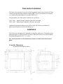
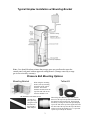
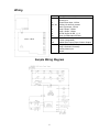
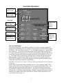
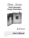
Titan Series
Pressure Activated
Pump Controllers
By CSI Controls
____________________________________
User’s Manual
1025731 Rev. B
Titan Series Controllers
The Titan Series consists of two cULus 508 Recognized control circuit boards: the Titan
control board and the Digital Interface Board (DIB). These circuit boards are connected
via a ribbon cable and mounted on a molded ABS bezel.
The part numbers for Titan Series Controllers are as follows:
CSLC-1801
CSLC-1802
Simplex Pump Controller w/Pressure Activation
Duplex Pump Controller w/Pressure Activation
(Additional designation characters may follow at the end of these part numbers to
indicate special options, such as time dosing, etc.)
Installation
The Titan bezel is designed to be mounted on a panel by eight screws. The panel cut-out
dimensions and screw hole locations are shown in the figure below. Screw holes should
be drilled and tapped for 6-32 x ½” screws.
The Titan Controller is to be mounted only indoors or inside an enclosed control
panel.
Controller Dimensions
(All Dimensions shown in inches)
2
Typical Simplex Installation w/ Mounting Bracket
Note: Care should be taken to insure that sewage gases are not allowed to enter the
control panel, seal panel with an approved sealing means! (Damage caused by sewage
gas is not covered by warranty).
Pressure Bell Mounting Options
Mounting Bracket
When using the mounting
bracket, start by mounting
the bracket on the wall of
the tank. The bracket
should be mounted near the
top of the tank with access
from the manhole cover.
The Installer Will Also Need:
Tether Kit
When using the tether kit simply slide the 8 lb
donut over the top to the pressure bell and thread
the nipple into the pressure bell. Then suspend
the bell by securing one end of the provided poly
rope to the bolt on the top of the nipple and secure
Installing
the
the other end
of the rope near
the top of the basin
with access from the manhole cover. Top mount
eyebolt is provided by the installer.
A length of 2”
PVC pipe long
enough to reach
the bottom of
the basin & 2”
Male Adaptor
3
Pressure Bell
Once the mounting bracket is installed, you will need to cut the PVC pipe to the desired
length. The length of the PVC pipe = Depth of Basin minus 14 inches (for the pressure
bell) and minus an additional 6 to 12 inches (so the pressure bell is off the bottom of the
basin). Once the length has been determined and the PVC has been cut attach the 2”
male adaptor to one end of the pipe.
Use pliers to slide tubing
clamp onto end of the
tubing approximately 1
inch.
Push tube onto barbed
fitting all the way, until it
is against the base of the
fitting. Then use pliers to
slide tubing clamp down
tubing to below the barb.
With the tubing
securely attached to
the pressure bell, feed
it through the PVC
pipe from the side with
the male adaptor
already attached.
*CAUTION!
Wear Eye Protection when installing tubing clamps, as they
can slip out of the pliers and become projectiles.
Finally, with the tubing
securely fastened to the
pressure bell and all the
tubing fed through the pipe,
thread the adaptor to the top
of the pressure bell (Hand
Tighten Only!).
Next, with the control panel mounted in a convenient location to the basin, attach the
other end of the 1/4” poly tubing to the control panel. Install spring clamps at the barbed
coupler similar to the manner described above. To help insure that your system does not
leak air it is best to not cut or splice the tubing. Leave enough extra tubing length coiled
up at the mounting bracket to allow the pressure bell to be removed from the basin for
maintenance. If your installation requires cutting the tubing to exit a junction box make
sure that you use the CSI brass coupler fitting with tubing clamps to insure a proper air
seal!
With all the 1/4” tubing connected, you will
need to remove the “Do Not Push or Pull the
Diaphram” sticker from the bottom of the
pressure bell. Do not push the bottom of the
pressure bell, but feel to make sure the rubber is
tight against the cup. If it is not, refer to the
section entitled “Seating the Rolling Diaphram”
before continuing. Also, make sure that all
tubing is connected between the pressure bell and the control panel before submersing the
bell in liquid. Note: Should the tubing become disconnected while the pressure bell is in
the liquid you will need to pump the station down manually before reconnecting the
4
pressure tubing. If there is an air leak or the diaphragm is not seated properly the system
will not give an accurate measurement.
Properly Seated Diaphragm
Improperly Seated Diaphragm
The proper operation of the rolling diaphragm assembly is key for the proper operation of
the pressure system. For the diaphragm to be seated, it must be snug around the push-cup
inside of the pressure bell assembly. The diaphragm is seated and protected when sent
from the factory. However, if the rolling diaphragm assembly has been pushed up by
some method other than water pressure (someone manually pushing on it), it will be
necessary to reseat the push cup in the diaphragm.
Reseating the Rolling Diaphragm
A diaphragm that is not seated properly must be reseated. Reseating the diaphragm can
be accomplished by plunging the pressure bell into a liquid depth of about three feet.
This must be done without the pressure tube connected to the controller. Once the
diaphragm is reseated, the rubber will be snug around the internal push-cup and when
lightly touching the diaphragm the push-cup can be felt immediately behind the
diaphragm. (An alternate method is to push the diaphragm up into the pressure bell as far
as it will go with your fist. Then put one finger over the end of the tubing that is
connected to the pressure bell. Now you can move around the diaphragm against the push
cup; make sure it is centered on the push cup. Then release your finger from the tubing
and the internal spring will slowly return the push cup to its default position.) Then make
sure the pressure tube is reconnected to both the pressure bell and the controller before
the bell is submerged in liquid.
Battery Backed Up Alarm
The controller’s alarm circuitry is 9-volt battery backed-up.
The 9-volt power will sound the audible alarm and light the
red alarm light on the front of the Controller. It will not light
the flashing red light on the top of the panel. To install the 9volt battery, access the back of the controller and insert the
battery into the clip on the circuit board as shown.
5
Wiring
Terminal
LA
N
LC
AUX, AL
LT
P2
P1
Off
RD
SL
V+
Aud
1
2
3
N
CSLC-180X
Description
Alarm Power Input, 120Vac
Neutral Input
Control Power Input, 120Vac
Auxiliary HL alarm dry contact
Alarm Light output, 120Vac
Pump 2 Output, 120Vac
Pump 1 Output, 120Vac
120VAC Output for RD, 1, 2, 3
Return for Redundant Off Float
Silence Detection Input
+12Vdc (Unregulated)
Audible Alarm output (Open Collector Output)
Pump 1 Overload / Overtemp
Pump 2 Overload / Overtemp
Auxiliary Alarm Input
Neutral
Sample Wiring Diagram
6
Controller Operation
Control Circuit
Power Light
Alarm Circuit
Power Light
Set Points
Alarm Light
& Test /
Silence
Button
Adjustable High
Level Alarm
Adjustable Lag
Pump On Dial
Adjustable Lead
Pump On Dial
Hand Run
Buttons &
Pump Run
Lights
Adjustable
Pumps Off Dial
The Level Set Points
The Pressure Systems are very simple to set and use. Each level setting is adjusted by
turning the corresponding dial. For example, using the duplex controller turn the pumps
off dial to 4”, the Lead Pump On dial to 12”, the Lag Pump On dial to 24”, and the High
Level dial to 36”. As the level in the basin comes up the LEAD PUMP will turn on at
12”, and LAG PUMP will turn on at 24” (with a 10 second delay), and as the liquid level
in the basin is being pumped down the pumps will shut off at the PUMPS OFF level of
4”. If for some reason a pump fails or the liquid level is coming into the basin quicker
than the pumps can remove it, the liquid level in the basin will eventually reach the
HIGH LEVEL setting of 36” and at this point the system will sound the audible and the
alarm light will flash two flashes per second (fast).
Remember: All settings are relative to the top of the large union nut on the pressure bell
in the basin.
The Pressure Systems also contain an internal low level / loss of pressure alarm. This
feature comes from the factory turned off, but can be enabled through the display. This
alarm will occur if the liquid level falls below 3”, or if the system air pressure is lost.
The PUMP OFF setting can not be set below 4” so that the level in the basin will never
be below the 3” level under normal operating conditions. Should this situation occur the
user has a few options of how they would like to be notified of the problem (See Low
Level Alarm menu on page 12).
7
Hand-Off Auto Operation
The “HAND” button on the Titan controller works similarly to a traditional
H-O-A toggle switch. There are three modes that each pump can be in: Hand, Off,
and Auto. In Off mode, the pump is disabled and will not run. To show that the
pump is disabled and will not run, its respective Pump Run LED will flash. In
Auto mode, the pump(s) will run as described in the sections below. In Hand
mode, the pump will run regardless of the Pump On setpoint or the Time Dosing
timers.
The first time the “HAND” button is pressed, the pump status on the LCD screen
will flash, showing that it is being edited. Pressing “HAND” again will cycle
through the three pump options. When the button has not been pushed for 3
seconds, the pump will be put into the mode that is displayed, and the text will
stop flashing. When the pump is running in Hand, you may bring it out of Hand
by pushing the “HAND” button one time, at which point the pump will return to
its previously set mode. To protect the pump against running dry, the controller
will not latch into Hand mode if the liquid level is below the Pump(s) Off
setpoint. To force the pump to run in Hand mode after this point, you must push
and hold the “HAND” button.
Also, if the pump’s overload/overtemp input opens, the pump will be disabled and
flash the Pump Run LED just as in the Off mode. In this case, the alarm will
sound and the pump status on the display will show “Fail.” If a pump has failed it
can not be forced to run with the hand button until the failure has cleared.
The operation detailed below is considered standard operation. Standard operation may be modified
by some controller settings. See “Menus” section for more details.
Basic Operation (Standard Simplex Controller)
When the liquid level in the basin rises to the Pump On setpoint, the pump will
turn on. The pump will stay on until the liquid level is below the Pump Off
setpoint or float. If the liquid level gets all the way up to the High Level setpoint,
the high level alarm will sound the audible and flash the alarm light. To silence
the audible, press the TEST/SILENCE button on the face of the controller, or use
an external switch to connect the SL terminal to ground (see sample wiring
diagram).
Basic Operation (Standard Duplex Controller)
When the liquid level in the basin rises to the Lead Pump On setpoint, the lead
pump will turn on. The pump will stay on until the liquid level is below the
Pumps Off setpoint. After the pump turns off, the pumps will alternate. (For
example, if Pump 1 is the lead pump, after it turns off, Pump 2 will be the new
lead pump, and Pump 1 will now be the lag.) However, a permanent Lead Pump
may be assigned in the Level Control Options Menu. If the liquid level gets all
the way up to the Lag Pump On setpoint, the lag pump will also turn on. A nonadjustable delay causes the Lag Pump to wait 10 seconds to turn on after the Lead
Pump turns on. If the liquid level gets all the way up to the High Level setpoint,
the audible will sound and the alarm light will flash. To silence the audible, press
the TEST/SILENCE button on the face of the controller, or use an external switch
to connect the SL terminal to ground (see sample wiring diagrams).
8
Basic Operation (Simplex Time Dosing Controller)
When the liquid level in the basin rises to the Pump On setpoint, the pump will
turn on. The pump will stay on until the liquid level is below the Pump Off
setpoint, or until the Pump On timer expires, whichever comes first. The pump
will then not be allowed to run again until the Pump Off timer expires and the
liquid level is above the Pump On setpoint. If the liquid level gets all the way up
to the High Level setpoint, the pump will turn on regardless of the state of the
Pump Off timer. This is called a Timer Override. The pump will run for the
Override On time, or until the liquid level is below the Pump Off setpoint,
whichever comes first. After it turns off, the Override Off timer will begin, and
the pump will not be allowed to run again until it expires, even if the liquid level
rises above the High Level setpoint again. The high level alarm is also activated
by the High Level setpoint, after the adjustable High Level Time Delay. This
delay allows the Timer Override time to pump the liquid down below the high
level before it alarms. To silence the audible, press the TEST/SILENCE button on
the face of the controller, or use an external switch to connect the SL terminal to
ground (see sample wiring diagrams).
Basic Operation (Duplex Time Dosing Controller)
When the liquid level in the basin rises to the Lead Pump On setpoint, the lead
pump will turn on. The pump will stay on until the liquid level is below the Pump
Off setpoint, or until the Pump On timer expires, whichever comes first. The
pump will then not be allowed to run until the Pump Off timer expires. After the
pump turns off, the pumps will alternate. (For example, if Pump 1 was the lead
pump, after it turns off Pump 2 will be the new lead pump, and Pump 1 will now
be the lag pump.) If the controller is in 2-field mode, the new lead pump will be
able to run as soon as the level rises back up to the Lead Pump On setpoint. In 1field mode, no pump can run until the Off timer of both pumps has expired. If the
liquid level rises to the Lag Pump On setpoint, the pump will turn on regardless of
the state of the Pump Off timer. This is called a Timer Override. In 2-field mode,
the lag pump will also turn on after a 10-second lag delay. The pump(s) will run
for the Override On Time, or until the liquid level is below the Pump Off setpoint,
whichever comes first. After it turns off, the Override Off timer will begin, and
the pump(s) will not be allowed to run again until it expires, even if the liquid
level rises above the Lag On setpoint again. If the liquid level rises all the way up
to the High Level setpoint, the High Level alarm will sound the audible and flash
the alarm light. To silence the audible, press the TEST/SILENCE button on the
face of the controller, or use an external switch to connect the SL terminal to
ground (see sample wiring diagrams).
Redundant Off Float Operation
The default operation of the off float, when used, is to disable automatic pump run
operation when the float tips down. If a Redundant Off float is not to be used, this
input should be jumped out. When a special alternate Redundant Run/High Level
function is used, the high level alarm will be activated and the pump will run
whenever the float is tipped up. If the Redundant Run/High Level float is not to
be used in this application, this input should be left open.
9
Menus
10
Menu Navigation
To advance to the next menu, press the “Menu/Enter” button. When in the display
menu, to go to the main menu, push and hold “Menu/Enter” until you see the
“Level Cntrl Menu” appear on the LCD screen (about 3 seconds). When in the
Main Menu, to select a submenu, press the “Set/Change” button.
Editing Fields
To edit the setting currently being displayed on the screen, press the “Set/Change”
button. The value that is now being edited will begin to flash. To change this
value, press the “Set/Change” button. To move to the next edit digit, or to finish
editing the setting, press the “Menu/Enter” button.
Display Menu
Press Menu/Enter Button to change between menu fields
Depth/Pump Status
Reads out liquid level in feet and inches. (Max value: 10’ 00.0”)
Shows pump mode: Hand, Off, Auto, or Fail
(Fail shows during overload or overtemp)
Elapsed Time # - (# is Pump number (1 or 2)):
Reads out the total elapsed run time of the corresponding pump.
(Max Value 999999:59:59)
Time shown is in the format of [Hours:Minutes:Seconds.]
Cycle Count # - (# is Pump number (1 or 2)):
Reads out the number of cycles the corresponding pump has
run. (Max Value: 999999)
Override Count - (Time Dose controllers only):
Reads out the number of times the panel has gone into override mode.
(Max Value: 999999)
High Level Count Reads out the number of times the liquid level has reached high level.
(Max Value: 999999)
Pump # (1 or 2) Timer - (Time Dose Controllers only):
Reads out the remaining time in the current time cycle. If the pump is
running then it indicates the time remaining until the pump shuts off. If the
pump is off then it indicates time remaining until the pump may run again.
Active Alarm
Reads out what alarm condition the panel is currently experiencing. If
there are no alarms, it will read “None”
11
User Settings Main Menu
Press and hold Menu/Enter Button for 3 seconds while in the Display Menu
to enter into this menu. Press the Menu/Enter Button to change between
menu fields.
Level Cntrl Menu - (Level Control Options Menu):
Press Set/Change button to enter into this sub-menu.
Time Dosing Menu - (Time Dosing Options Menu, Time Dose controllers only):
Press Set/Change button to enter into this sub-menu.
Telemetry Menu - (Modem option only):
Press Set/Change button to enter into this sub-menu.
Alarm History
Press Set/Change button to enter into this sub-menu.
Level Setpoints Press Set/Change button to enter into this sub-menu.
Level Control Options Menu
Lead Pump Set (Duplex Controllers Only):
Press Set/Change button to change this field.
Possible Settings:
Alternate =
Pump 1 is Lead =
Pump 2 is Lead =
Alternate which pump turns on at the lead setpoint
every time a pump runs
Pump #1 always turns on at the lead pump setpoint.
Pump #2 always turns on at the lag pump setpoint.
Pump #2 always turns on at the lead pump setpoint.
Pump #1 always turns on at the lag setpoint.
Low Level Alarm – Occurs if liquid level reads below 3.5”
Press Set/Change button to change this field.
Possible Settings:
Alarm Off
= Low Level Alarm Off
Light Only
= Flash Alarm Light only for Low Level Alarm
Light & Audible = Flash Alarm Light and sound audible for Low
Level Alarm
Reset Cyc Cnt # - This is the cycle count that can be viewed in the Display Menu
(Reset Cycle Counter to zero, # is Pump number (1 or 2))
Press Set/Change button to change this field.
12
Possible Settings:
Do Not Reset = Cycle Counter will not reset
Reset Counter = Cycle Counter will reset to 0
Reset E.T.M. # - This is the Elapsed time that can be viewed in the Display Menu
(Reset Elapsed Time to zero, # is Pump number (1 or 2))
Press Set/Change button to change this field.
Possible Settings:
Do Not Reset = Elapsed Time will not reset
Reset Counter = Elapsed Time will reset to 0
Time Dosing Options Menu (Time Dose Controllers Only)
Pump # Time On - (Pump Enable Time Setting, # is Pump number (1 or 2))
This is the amount of time the pump will be enabled to run once the level
reaches the “Pump On” (simplex) or “Lead On” (duplex) setpoint. Note: If
the level reaches the pump off setpoint before time expires, the pump will
shut off and the Pump Disable time will begin.
Time shown is in [Minutes:Seconds] (Maximum time setting is 99:59)
Press Set/Change button to change this field.
Pump # Time Off - (Pump Disable Time Setting, # is Pump number (1 or 2))
This is the amount of time the pump must wait after it completes a run
cycle before it may run again. Note: If the level reaches the override (lag)
setpoint the pump will begin to run regardless of Pump Disable Time.
Time shown is in [Hours:Minutes] (Maximum time setting is 99:59)
To disable Time Dosing, set this field to 00:00.
Press Set/Change button to change this field.
Pump # Ovrrid On - (Pump Enable Time Setting for Override, # is Pump
number (1 or 2))
This is the amount of time the pump will be enabled to run once the level
reaches the override setpoint, at which time the system enters the Override
Time Dosing mode.
Time shown is in [Minutes:Seconds] (Maximum time setting is 99:59)
Press Set/Change button to change this field.
Pump # Ovrrid Off - (Pump Disable Time Setting for Override, # is Pump
number (1 or 2))
This is the amount of time the pump must wait after it completes an
Override run cycle before it may run again. Note: The pump will continue
13
to cycle in override time dosing mode until the level is below the override
setpoint when the Override Pump Disable Time expires.
Time shown is in [Hours:Minutes] (Maximum time setting is 99:59)
Press Set/Change button to change this field.
Alarm/Override
This setting controls 3 functions of Time Dosing:
Override: When the basin level reaches the Override setpoint (High Level
setpoint on simplex, Lag setpoint on duplex), the panel will
override the Off Timer, and run the pump(s) using the override On
and Off times.
Override Warning: When an override occurs, the panel will sound an
Override Warning Alarm, to signal that an override event is
occurring.
High Level Alarm: When the basin level reaches the High Level setpoint,
the panel will sound a High Level Alarm, to signal that the liquid
level is much higher than expected.
Override
Warning
Override w/Alarms
ON
ON
Override-No Warn
ON
OFF
Overide-No Alrms
ON
OFF
Alarm-No Overide
OFF
OFF
Press Set/Change button to change this field.
Setting
Override
High Level
Alarm
ON
ON
OFF
ON
High Level Delay - (High Level Time Delay, Simplex Controllers Only):
The High Level Alarm will delay according to the set time. If the fluid
level is above the High Level set point for this length of time without
interruption the alarm will begin to sound. Time shown is in
[Minutes:Seconds] (Maximum time setting is 99:59)
Press Set/Change button to change this field.
Number of Fields – (Duplex Controllers Only)
The Time Dosing operation can be set up for One Field or Two Fields.
When set to “Two Fields” each pump will be able to run as soon as its
corresponding Off Timer is complete. During override the two pumps may
run at the same time.
When set to “One Field” each pump will only be able to run when the Off
Timer for both pumps is complete. The two pumps will never run at the
same time.
14
Telemetry Menu (Modem Option Only)
Call Number
Displays the telephone number the modem will call to report alarms and to
check in monthly. This field may hold from 1 to 11 digits.
Press Set/Change button to change this field. Enter the number 1 digit at a
time. If entering less than 11 digits, enter a blank character to signify when
the telephone number has been entered completely.
Note: This number is set at the factory and will not need to be changed
under normal operation.
I.D. Number
Displays the unique identification number assigned to the control panel.
This field will not normally need to be edited. (May contain the numbers
0-9 and the characters A-F.)
Press Set/Change button to change this field.
Note: This number is set at the factory and will not need to be changed
under normal operation.
Initiate Check-In
Press Set/Change button to force the modem to call in. Emails and text
messages will not be sent for this notification. This menu will also display
the status of the modem connection.
Alarm History Menu
This menu displays the last three alarms that have occurred, beginning with the
most recent alarm. On Titan Controllers equipped with a modem, this menu will
also display the date and time the alarm condition occurred.
Level Setpoint Menu
When the dials are adjusted, LCD screen will jump to display this menu for 10
seconds to aid in precision.
Off Setpoint
Displays the level in feet and inches to which the Pump(s) Off dial is set.
Pump On Setpoint (Simplex)
Displays the level in feet and inches to which the Pump On dial is set.
Lead Setpoint (Duplex)
Displays the level in feet and inches to which the Lead Pump On dial is
set.
15
Lag Setpoint (Duplex)
Displays the level in feet and inches to which the Lag Pump On dial is set.
Hi Levl Setpoint
Displays the level in feet and inches to which the High Level dial is set.
Auxiliary Inputs
There are three Auxiliary Inputs (labeled 1, 2, and 3) on the DIB, each with its
own alarm. Each has a 120Vac input, and all three share a common Neutral. The power
to these inputs should come from terminal OFF, or a fused 120Vac source; all three
inputs must use the same source.
Inputs 1 & 2 are for normally closed contacts, and are specifically used for pump
1 & 2 heat sensor and/or overload. Input 3 is for normally open contacts, and is a general
panel alarm.
Input Rating: 120 Vac, 10mA each
16
Troubleshooting
Each different alarm is annunciated on the LCD screen. The audible and alarm
light also flash at different rates for each alarm. The alarm conditions are explained in the
chart below:
Alarm/Fault
High Level
Low Level
Timer Override
Alarm Power Fail
Alarm Light Flash Audible Flash
Other Indication
2 per sec.
2 per sec.
Aux. Contact Closed
1 every 2 sec.
Chirp every sec.
X
1 every 4 sec.
1 every 4 sec.
X
X
1 every 4 sec. Alarm Power LED Off
Alarm Fuse LED Off
Control Power Fail
1 every 4 sec.
1 every 4 sec. Control Power LED Off
Control Fuse LED Off
Alarm Fuse Fail
X
1 every 4 sec. Alarm Power LED Off
Alarm Fuse LED On
Control Fuse
1 every 4 sec.
1 every 4 sec. Control Power LED Off
Control Fuse LED On
Pump 1 Fault
1 long, 2 short
1 long, 2 short
Pump 1 LED Flash
Pump 2 Fault
1 long, 2 short
1 long, 2 short
Pump 2 LED Flash
Auxiliary Input Alarm
1 long, 2 short
1 long, 2 short
X
Pump 1 is turned Off
X
X
Pump 1 Run LED Flash
Pump 2 is turned Off
X
X
Pump 2 Run LED Flash
FCC Information
The Federal Communication Commission (FCC) has established rules, which permits this device to be directly connected to the
telephone network. If this device is malfunctioning, it may also be causing harm to the telephone network; this device should be
disconnected until the source of the problem can be determined and until repair has been made. If this is not done, the telephone
company may temporarily disconnect service. The telephone company may make changes in its technical operations and procedures;
if such changes affect the compatibility or use of this device, the telephone company is required to give adequate notice of the
changes. If the telephone company requests information on what equipment is connected to their lines, inform them of the following:
a) The telephone number the device is connected to.
b) The ringer equivalence number (REN).
c) The device uses an RJ11 type jack.
d) The FCC Registration Number.
The REN (Ringer Equivalence Number) is used to determine the number of devices that may be connected to the telephone line.
Excessive RENs on a telephone line may result in devices not ringing in response to an incoming call. In most, but not all areas, the
sum of the REN should not exceed five (5.0). To be certain of the number of devices that may be connected to a line, as determined by
the total RENs, contact the local telephone company.
17
Specifications
Dimensions
10.72"h X 9.85"w X 0.76"d
Mounting
Panel Mount, w/ eight 6-32 x 1/2" screws
Weight
1.5 pounds
Alarm Power Input
115Vac
Control Power Input
115Vac
P1, P2 Output
115Vac, 100 mA max.
LT Output
115Vac, 100 mA max.
Aud Output
Open Collector Output, 75mA max.
V+ Output
+12Vdc, unregulated
Float Input
120Vac, 10 mA max.
Aux Inputs
120Vac, 10 mA max.
Aux Alarm Contact Rating
120Vac, 5A max.
Fuse Rating
5mm x 20mm, 3 Amps max.
Terminal Torque Ratings
7.0 inch-lbs.
Controller Temp Range
-40°F (-40°C) to +185°F (85°C)
Humidity
95% non-condensing
Non-Conductive Injection Molded Bezel
Provides NEMA 1 Rating (when mounted through an enclosure)
Blown Fuse Status Lights
3 Year Limited Warranty
CSI Controls, 220 Ohio Street, Ashland, Ohio 44805
Phone 419-281-5767 · Toll Free 1-800-363-5842 · FAX 419-289-2535
©2010 CSI Controls
www.CSIcontrols.com
[email protected]
18