1
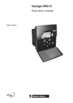
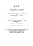
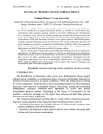
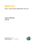
2.
BASIC DESCRIPTION OF THE SYSTEM
Contents
2.
BASIC DESCRIPTION OF THE SYSTEM ............................................................................................................. 7
CONTENTS ............................................................................................................................................................................ 7
2.1 CONVENTIONS ............................................................................................................................................................ 7
2.2 BASIC ELEMENTS OF THE SYSTEM SCREEN ............................................................................................................... 7
2.3 MAIN MENU ................................................................................................................................................................ 9
2.4 ATTRIBUTES OF DISPLAYED SIGNALS AND MEASUREMENTS..................................................................................... 9
PROCESSING OF SIGNALS............................................................................................................................................. 12
2.5 CHANGE SIGNALS ..................................................................................................................................................... 13
2.6 PROCESSING OF MEASUREMENT .............................................................................................................................. 17
2.1 Conventions
The WMDisp2.exe program i.e. “Mikrodispečink display unit” is prepared and tested for the
platform OS MS Windows 2000, XP, 7. For the requirements of this user manual these operating systems will
be referred to as Windows for short.
The control of the application is usually performed by means of the mouse. Clicking with the mouse
means a brief pressing of the mouse button. If it is not stated which button to press, it concerns the left button
by default. Clicking with the left button is used to select and confirm the respective function. Clicking with
the right button is used to open the respective menu window. Movement with the mouse means positioning
the cursor over the menu item whose text for the standard set colour Windows diagram is backlit in blue (i.e.
move the mouse cursor over the respective menu item without clicking). References to selection of the item
from the respective menu are written in this manual in bold italics, e.g. Images means select (click with left
mouse button) the item “Images” from the respective menu.
References to the pressing of keys are written in the manual in bold between the characters < >, e.g.
<M> means press key M. Pressing of more keys is written as <Ctrl S>, this means, press button Ctrl, hold it
and then press key S. The last option for pressing keys is the combination <Ctrl K> <K>, this means
pressing key Ctrl, hold it and press key K, release the keys and press key K.
If it appears that the system cannot be controlled, press button <Esc> (you can be located in a
function in progress). If Esc does not help, then it is probably a system error. The main features of the system
“freezing” are the non running of the time on the auxiliary bar or the mouse cursor cannot move.
2.2 Basic elements of the system screen
After running the initial initialisation, the Mikrodispečink window appears where all the program
functions can be typed. The basis of the system is the windows which can change the size and location on the
monitor screen. The control of the program can be divided into two parts, control and manipulation with
individual windows and control of diagrams, diary, etc. Both parts can be controlled using the mouse, or with
restrictions from the keyboard. Individual windows can be moved on the working part of the screen and
placed where necessary. Parts of windows which are opened are automatically restored. All data is always
updated. In the case of higher requirements for the volume of displayed data, it is possible to connect further
User description of control system MDisp
-7-
May 2010
monitors to one computer on which the selected continuous part of the virtual screen is displayed. The
number of monitors is stated by the HW options of the computer.
Practically, the Mikrodispečink window is designed as follows. In the upper part is the
Mikrodispečink header, the main user menu and auxiliary bar. The working area occupies a significant part.
Mikrodispečink header
1
2
Main menu
3
Auxiliary bar
4
5
Working area
Fig. 1 Basic screen of the system
The header of the Mikrodispečink window contains auxiliary information for the system service.
In the header of the window are the “icons”. These are graphic marks for working with the window by using
the mouse. The movement of the mouse on the icon and clicking of the left button will execute the respective
function.
The basic functions of the system are offered in the main menu.
The Auxiliary bar contains icons for magnifying and minimising the image in the actual window (1),
menu for selection of the size of the image in the actual window (2) within the range 10 to 200 %, icon for
selection of the navigation window of the image (3), menu containing the names of all open windows within
Mikrodispečink (4), menu for sending SMS and e-mails to selected addresses (5) – clicking by mouse on the
selected name of the window, this window becomes active. It also contains the actual day in a week, date and
time.
The working area of the screen serves for the arrangement of opened windows – their quantity is not
restricted by the program. The window is the part of the screen which is specified and bordered. The size of
most windows can be changed, it is possible to relocate windows outside the working area, it is possible to
close and open further separate windows or the tab windows, to relocate the tabs from one tab window to the
other and back, to move the tab into the new tab window. All functions are described in the “Windows”
chapter. In the upper part of the window is the “window header”. The background of the header of the actual
window for the standard setting of the colour scheme Windows has a blue colour (this scheme can be
changed in “Control panels” Windows – the colour of the background of the header then corresponds to the
respective setting), the description in the header describes the function of the respective window. In the
frame of the window are the “icons” for working with windows by means of the mouse.
User description of control system MDisp
-8-
May 2010
2.3 Main menu
The basic functions of the system are offered in the main menu. Select the respective item to enter
into the system menu. Individual basic menu items are evident from the following diagram.
2 Main menu
The menu can be controlled using three methods:
using the mouse – moving and clicking on the respective menu item,
using the cursor keys (arrows, Home, End, PageUp, PageDown),
using the highlighted letters in the menu.
By moving the cursor onto the item in the main menu and clicking with the mouse (on the item
“Confirmation”) the further respective menu is opened. If the line of this menu contains a black arrow at the
right edge - it is information that after the movement of the mouse to this line, the further menu (sub-menu) is
automatically opened. Click with the mouse on the menu item to open and confirm the respective function; it
is not necessary to press any key.
Use the key <F10> to go to the line in the main menu. After pressing the mentioned key some of
menu items will be backlit. Use the cursor keys to select the required item and the option is confirmed by
means of the key <Enter>.
In the case of selection by highlighting letters, the selection is not confirmed, the function is
performed immediately. Selection by means of highlighted letters means pressing the key with the letter
which is highlighted in the actual menu. If you want to select a menu from the windows environment, this
means without pressing the key <F10> at the same time is necessary to press the key <Alt>. This is valid only
for the first opening of the menu, then it is selected only by pressing the key with the highlighted (underlined)
letter.
If in menu the key or combination of keys <Alt X> is displayed then pressing this key or the
combination of keys will activate the same program function without the necessity to use the menu.
Select Confirm from the main menu to confirm the horn and beeping.
This documentation contains the description of the menu in the maximum configuration. In most
cases not all items will be available for the user which depends on the permitted authority which the system
administrators will make accessible.
2.4 Attributes of displayed signals and measurements
Signals and measurements have the assigned attribute which states their quality or their source. We
distinguish the following quality – attributes: telemetric, manual non-rewritable, manual rewritable,
doubt value, planned value, semi-position and telemetric error.
The meaning of individual qualities is as follows:
• Telemetric – this attribute indicates values which are measured and are actual. It is not
possible to manually set this attribute. For measurements it is indicated by the symbol "!" and
the blue colour of the displayed value. The full element is used for signalling in the colour
corresponding to the status; green – OFF, red – ON. Changes of these values are transferred
into the neighbouring system always with the "telemetric" attribute.
• Manually non-rewritable – the attribute indicates the values which are manually typed and
cannot be rewritten by a telemetrically measured value. It is used, for example, for the values
for which it is known that an erroneous value is remotely transferred. It is indicated by the
symbol "=" and a yellow colour for measurement; for signals the attribute is written in the
displayed element, for the colour the same rules are valid as for telemetric attributes. It is not
User description of control system MDisp
-9-
May 2010
possible to rewrite this value by the input from the other system. In the case of a change, the
value with the “manual rewritable” attribute is sent into the neighbouring systems.
• Manually rewritable – the attribute indicates the values which can be rewritten by measured
data. The first received telemetric values change this attribute to telemetric. If the telemetric
value came before the change of the attribute to a re-writable value, the telemetric value is
displayed immediately. The indication is by means of ":" and the white colour for
measurement; for signals the attribute is written in the displayed element, for colour the same
rules are valid as for the telemetric attributes. It is possible to rewrite these values with input
from another system; the criterion is the time of the manual change – the last manual input will
be stored in all linked systems.
• Doubt value – is the attribute which is displayed for the values if the telemetric attributes are
not updated, e.g. in the case of a breakdown of routes. This value is changed immediately after
the restoration of the receipt of telemetric data. All values after resetting the database and all
elements of databases for which a global doubt is set are indicated. The database is globally
doubted in the case of a breakdown of the route or after the disconnection of the communication
computer; back setting of attributes is automatically performed after restoration of
communication between systems. The indication is "?" and a light-grey colour for
measurement; for the signals an empty element is used, for colour the same rules are valid as for
the attribute telemetric.
•
Telemetric error – this attribute has an oscillating signal or measurement for which an input
error occurred (defective equipment – card of inputs).
• Planned value – this attribute is used for marking measurements which are not transferred
remotely (telemetrically) and their value is always typed manually. The indication is by means
of "&" and a white colour; this attribute can only be used for measurement In the calculations
this value does not devalue (influence) the resulting attribute. It is transferred into the linked
systems as the planned values.
• Semi-position – the attribute is used only for two-bit signalling and means that the signalled
element, e.g. the disconnector, is in a semi-position. The semi-position is evaluated as the same
status of both positions ( 00 or 11 on the input). The semi-position status is reported after
expiration of the time filter which can be separately set for each element. An empty element
with a white colour is used.
The above-mentioned appearance of signals for individual statuses and attributes can be changed by
the user.
Manual non-rewritable, manual rewritable and planned value (only for measurements) – are set
by clicking with the right mouse button on the selected signal or the value of measurement and in the
displayed menu window the item Manipulation with the signal (for signal) or the item Manipulation with
measurement (for measurement) is set. Selection will result in the opening of the respective window where
the listed attributes can be interactively selected using the mouse – see Chapter “Figures”. In the case that the
attribute manual non-rewritable is selected and there is the telemetric value or semi-position, then after the
change to the attribute manual rewritable the attribute telemetric or semi-position is displayed. The
attributes telemetric, doubted, telemetric error and semi-position are generated by the system, they cannot
be set it in another manner. The attributes semi-position and telemetric can only be overwritten by the
attribute manual non-rewritable.
User description of control system MDisp
- 10 -
May 2010
Attributes have various weights which then state the attribute of the concerned values. The
calculated values have the lowest attribute from the values represented by additional calculation. This means
that only one value with a doubted attribute will doubt the calculated value. This rule is valid for signals, as
well as for measurement.
Weights of attributes:
"telemetrically"
- highest attribute
"manual non-rewritable"
"manual rewritable"
"telemetric error"
"semi-position"
"doubted"
- lowest
"planned value" - does not influence the resulting attribute.
User description of control system MDisp
- 11 -
May 2010
Processing of signals
Changes in signals can be divided into:
manual – called up by the mouse in the respective system
telemetric – inputs of signals in the respective system
automatic – manual and telemetric changes passed through the communication channel from the
neighbouring system
Manual changes are written directly into the acknowledged diary (according to setting, see below); do
not call up the flashing or activate the horn.
During the entrance into the system, first of all the signal is stored in the database. It is stored into
the database with the time. This time is either the time when the change occurred (signal entered into the
system with the time) or the time when the signal was registered in the system. If during the storage into the
database the change of the status or the attribute of the signal is evaluated, then the flashing of the element is
set (processing No.0.2). In the database is the additional calculation, if defined to the respective element, and
the assigned change element is set. After saving into the database it is checked whether the element is stored
into the diary. Storage into the diary is always performed when the values come with the time and also when
there was a change in the status or the attribute. Changes “from” or “into” the “doubted” attribute are not
recorded into the diary. Saving into the diary is specified by the type of processing (see the following table)
and the number of the diary (stated in the database). The number of the diary serves for classifying the diary
during the display. It is possible to block for a temporary period, the recording of signals in the database
directly in the live system; for a detailed description of this function see below.
The behaviour of the element is defined in the database of the type of elements in which there is a list
of all elements used in the system and a description of their properties. These properties are defined by the
system administrator. Properties are characterized by:
the type of processing,
number of the diary,
additional calculation,
change signal,
The following types of processing can be selected:
TYPE OF PROCESSING
0
1
2
3
acknowledged record into the diary “ON” and
“OFF”
-
X
-
-
unacknowledged record into the diary “ON”
X
-
X
X*
unacknowledged record into the diary “OFF”
X
-
-*
X**
indication on the change line
X
-
X
X**
activation of the horn
X
-
X
X**
activation of flashing of the element
X
-
X
X**
activation of change signals
X
X
X
X**
X means performing the respective response. Most signals will have standard processing 0; only special
signals will have other processing.
*In the case of the change ON and OFF, the item is saved into the diary although its mask is set which
causes that the line is not displayed during browsing (use for instantaneously viewing signals from
protective systems).
**Items are processed only in the case where it concerns a real change of the status or the attribute.
A detailed description of the behaviour of the signals after coming into the system is described in
Appendix No. 1. It is possible to define the behaviour within the administration of the system.
User description of control system MDisp
- 12 -
May 2010
Each signal has a diary number which can have values from 0 to 31 for each voltage level. Diary
numbers are assigned to individual signals in the uniform type database. Changes of signals with the diary
number 0 are not recorded into the diary. The diary number serves for masking individual lines during the
display. Acknowledgement of automatic changes in the diary cancels the flashing of the element.
Fig. 3 Mask for lines in the diary (Mask for the screen)
It is possible to create calculated elements - additional calculations or logical sums, products
and signal negations. Changes of calculated signals flash up to the acknowledgement of all changes
representing the calculation. The status of the calculated element can be changed only by the change
of the element which the calculation represents. Attributes are calculated according to the weight
(quality). The calculated element will have the attribute with the lowest quality from the attributes of
the elements representing the calculation.
2.5 Change signals
A special type of elements are 16 change signals. They are always located in each signals database
from the address 1980 to 1995. The system of change signals enables the dispatcher to quickly orientate in the
changes at the following levels:
managed area (max. 64 change signals, 4x16),
sub-stations (max. 64 change signals, 4x16),
objects, individual elements
One of Q14 change signals can be assigned to each signal from the type of signals database. In the
case of any changes in the status or the attribute of the basic signal, the calculation of the change signal is
performed so that the result is stated by the sum of the statuses which have the same change signal. The
attribute of the change signal can be manually non-rewritable if any of values has this attribute set or
telemetric in other cases. Change of the status on this element is not possible. The change signal has the flag
User description of control system MDisp
- 13 -
May 2010
for flashing during the time when any of the signals flash from which the calculation is performed. The
flashing of the basic signal cannot be cancelled by a simple acknowledgement of the change signal.
At addresses 1994 and 1995 are two signals which serve for signalling the exceeding of limits in the
measurement databases. The first signal serves for monitoring between dispatching and system measurements
and the second is a reserve. In the case of exceeding limit I or II, the flag for flashing is set on the respective
change signal. This flag can be cancelled by direct acknowledgement of the flashing measurement. The
status of the change signal is set for “ON” if any of its values are outside the limit. The attribute has the same
meaning as for previous change signals.
A further change signal is signalled at the address 1996. This signal is stated as the sum of signals
1980-1995. Statuses, as well as attributes and flags for flashing are summarized here.
Change signals are summarized in each system. They are summarized according to the levels of the
databases into four groups for the change signals:
6, 10, 22kV, ... VN
110kV,
220, 400kV,
system and special databases.
The resulting 4x16 signals are always stored in the system database. In each system is the
definition of which databases are summarized into the result. The system administrator defines the
groups of databases; for example, according to controlled areas. The user with the respective
authority selects which groups of databases are summarized into the result according to which area is
controlled. The setting is always valid for the whole system.
User description of control system MDisp
- 14 -
May 2010
2.5.1
Working with change signals
The use of change signals is displayed in the following diagram.
1
2
3
4
5
6
7
10
11
12
8
9
Fig. 4 Use of change signals
In the window of the resulting change signals are the sums of the change signals from individual
databases (1). The selection of change elements which are displayed in this line is set by the system
administrator. Selection is from the group of 4x16 resulting signals.
In the case of any change, there is the recalculation of change signals and in the window of the
resulting change signals the status is changed or a particular element flashes. After clinking with the mouse
on this element, the change window is opened with the list of databases (2) according to the respective
voltage level where the element belongs. In the window on the individual lines are the names of databases (3)
and the respective change elements (4). These change in the signals display the resulting statuses of
individual signals and are permanently updated. If the change signal is not used in DBF, then a grey dot is
displayed instead of it. After clicking with the mouse on the respective change signal, the window with all
signals appears (5) assigned into this change signal. By clicking on the change signal which displays any
exceeding of the limit, it is possible to open the window containing the list of measurements assigned to the
respective change signal. By clicking with the right mouse button on the change element (4) or on the
User description of control system MDisp
- 15 -
May 2010
resulting change element (1) it is possible to select the item Open list of objects with the list of objects
contained in the database – window (8).
In the window (5) all signals are displayed (6) from the database which are the same change signal,
including statuses and attributes. (7). The sequence of values is calculated when opening the window and is
as follows:
unacknowledged statuses ON
unacknowledged statuses OFF
acknowledged statuses ON
acknowledged statuses OFF
Values are permanently updated. If during updating there is a change in the status or flashing, the
sequence of values is unchanged. The same operations can be performed on the displayed signals by clicking
with the right mouse button and selecting the respective item from the opened menu.
The change window in which exceeding the limits is displayed displays the values from the
measurement database. Values which exceeded the limit and were not acknowledged (in the diary or in the
change window or the figure) are shown in the list at the beginning and as flashing. After these are the other
values from the respective database. In this window the values can be handles as in the figures. It is also
possible to acknowledge the flashing values – by clicking with the right mouse button on the value of
measurement and selecting the item from the opened menu (in the case of acknowledgement of the value by
selection of the item Acknowledgement).
In the case of the display of the list of objects, the window is displayed (8), in which there is the list
of all objects (9) in the respective database. The text of the names of the objects is displayed in yellow for
distinguishing the display. After clicking with the mouse button on the respective object, the window is
displayed (10), in which there is the list of all signals and measurements (11) in the respective object together
with the actual values (12). The sequence order of values is as follows:
power elements,
other signalling from the object,
measurement of the respective object,
All signals and values displayed are permanently updated and it is possible to perform the same
operations as on the elements in the diagram.
All the mentioned windows are closed by means of the key <Esc> or by the standard closing of the
window. During the display the window does not need to be active; it can be hidden under the other
windows.
Note: The meaning of the other items displayed in the menu windows after clicking with the right
mouse button is given in the Chapter Diagrams. .
User description of control system MDisp
- 16 -
May 2010
2.5.2
Appearance of change signal icons
The following icons were created to display the change signals:
Fig. 5 Icons of change signals
1 - Change of the status of the switch
2 - Protection action
3 - Protection impulse
4 - Critical failure
5 - Non-critical failure
6 - Ground connection
7 - Critical failure of the computer system
8 - Non-critical failure of the computer system
9 - Exceeding of the measurement limit
10 - Sum element of signals
11 - Switching element
For change elements with the non-rewritable attribute this is displayed in the lower part of the icon.
These icons are backlit according to the groups of databases, in the following manner:
6, 10, 22 kV (VN)
- dark yellow
110 kV
- dark green
220, 400 kV
- dark red
system and special databases
- dark violet
On the appearance of the window with the resulting change signals it is possible to see the standard
icons currently used by the Mikrodispečink system:
Fig.6 Standard Mikrodispečink icons
Selection procedure and closing of this window for the resulting change signals is shown in the
Chapter “Figures”
2.6 Processing of measurement
Changes in measurements can be divided into:
manual – called up by the mouse and typed from the keyboard in the respective system
telemetric – inputs of measurements in the respective system
automatic – manual and telemetric changes passed through the communication channel from the
neighbouring system
User description of control system MDisp
- 17 -
May 2010
manual changes are recorded directly into the database where the time of the manual change is
assigned and any recalculation is made if the value is part of the recalculation.
Automatic changes of values are first recorded into the database. The time of registration is saved
into the database by the respective system. If the value is part of the recalculation, the recalculation is
performed. Moreover, there is the evaluation of the exceeding of limits which are recorded into the diary.
The system distinguishes two limits. The first limit I is the users and is set by the dispatcher The second
limit II is set by the system administrator and is user non-accessible. Both limits are identical in terms of
processing and independence. These can be set to a different value. Both limits are saved into the diary, even
in the case that they are set at the same value.
User description of control system MDisp
- 18 -
May 2010