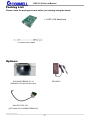
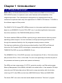
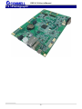
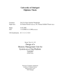
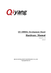
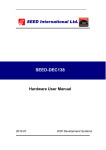
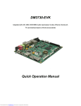
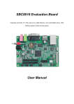
1
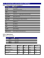
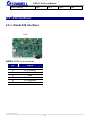
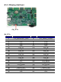
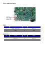
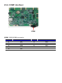
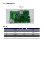
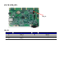
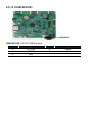
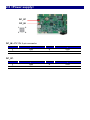
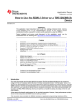
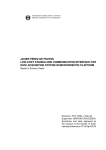
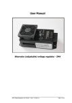
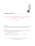
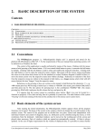
DSP-L138 Baseboard User’s Manual Edition 1.11 2015/09/24 DSP-L138 User’s Manual Copyright Copyright 2013, all rights reserved. This document is copyrighted and all rights are reserved. The information in this document is subject to change without prior notice to make improvements to the products. This document contains proprietary information and protected by copyright. No part of this document may be reproduced, copied, or translated in any form or any means without prior written permission of the manufacturer. All trademarks and/or registered trademarks contains in this document are property of their respective owners. Disclaimer The company shall not be liable for any incidental or consequential damages resulting from the performance or use of this product. The company does not issue a warranty of any kind, express or implied, including without limitation implied warranties of merchantability or fitness for a particular purpose. The company has the right to revise the manual or include changes in the specifications of the product described within it at any time without notice and without obligation to notify any person of such revision or changes. Trademark All trademarks are the property of their respective holders. Any questions please visit our website at http://www.commell.com.tw TU UT -1- DSP-L138 User’s Manual Packing List: Please check the package content before you starting using the board. 1 x DSP-L138 Baseboard 2 x stereo audio cables Options: SPD-030-5 D13-080SUTB00A0-S V1.0 (800x600 LCD with touch screen) OALLCD-T18C-C01: (LCD Cable for D13-080SUTB00A0-S) -2- DSP-L138 User’s Manual Index Chapter 1 <Introduction> ....................................0 1.1 <Product Overview> ...................................................................... 0 1.2 <Product Specification> ................................................................. 3 1.3 <Photograph> ................................................................................. 5 1.4 <Block Diagram> ........................................................................... 0 Chapter 2 <Hardware setup> ..............................1 2.1 <Connector & Jumper Location> ................................................... 1 2.2 <Connectors and Jumpers Setting> ................................................ 0 2.2.1 <Connectors and Jumpers> ................................................. 0 2.2.2 <Switches> .......................................................................... 0 2.5 <I/O interface> ............................................................................... 1 2.5.1 <Serial ATA interface> ........................................................ 1 2.5.2 <Ethernet interface> ............................................................ 0 2.5.3 <Display interface> ............................................................. 0 2.5.4 <Audio interface>................................................................ 1 2.5.5 <USB interface> .................................................................. 0 2.5.6 <COM1 interface> .............................................................. 0 2.5.7 <MMC/SD slot> .................................................................. 0 2.5.8 <J11> ................................................................................... 0 2.5.9 <JTAG> ............................................................................... 0 2.5.10 <CN_IO> ........................................................................... 0 2.5.11 <CN_IO1> ......................................................................... 0 2.5.12 <CN_IO2> ......................................................................... 0 2.5.13 <USB-XDS100> ............................................................... 0 -3- DSP-L138 User’s Manual 2.6 <Power supply> .............................................................................. 0 Appendix A <Boot SD Card> ...............................0 Appendix C <References> ......................................0 Contact information .............................................0 -4- Chapter 1 <Introduction> 1.1 <Product Overview> DSP-L138 is a motherboard that based on Texas Instruments OMAP-L138 C6-Integra DSP+ARM Processor to implement most useful features and functionalities of this integrated processor. This motherboard is designed to be a development board for customers to implement and verify their applications for OMAP-L138 features. TI DVSDK is the software support of this product. The OMAP-L138 C6-Integra DSP+ARM processor is a low-power applications processor based on an ARM926EJ-S and a C674x DSP core. It provides significantly lower power than other members of the TMS320C6000 platform of DSPs. The device enables OEMs and ODMs to quickly bring to market devices featuring robust operating systems support, rich user interfaces, and high processing performance life through the maximum flexibility of a fully integrated mixed processor solution. The dual-core architecture of the device provides benefits of both DSP and Reduced Instruction Set Compute (RISC) technologies, incorporating a high-performance TMS320C674x DSP core and an ARM926EJ-S core. The ARM926EJ-S is a 32-bit RISC processor core that performs 32-bit or 16-bit instructions and processes 32-bit, 16-bit, or 8-bit data. The core uses pipelining so that that all parts of the processor and memory system can operate continuously. The ARM core has a coprocessor 15 (CP15), protection module, and Data and program Memory Management Units (MMUs) with table look-aside buffers. It has separate 16K-byte instruction and 16K-byte data caches. Both are four-way associative with virtual index virtual tag (VIVT). the ARM core also has a 8KB RAM (Vector Table) and 64KB ROM. The device DSP core uses a two-level cache-based architecture. The level 1 program DSP-L138 User’s Manual cache (L1P) is a 32KB direct mapped cache and the Level 1 data cache (L1D) is a 32KB 2-way set-associative cache. The Level 2 program cache (L2P) consists of a 256KB memory space that is shared between program and data space. L2 memory can be configured as mapped memory, cache, or combinations of the two. Although the DSP L2 is accessible by ARM and other hosts in the system, an additional 128KB RAM shared memory is available for use by other hosts without affecting DSP performance. ARM926EJ-S Core 32-Bit and 16-Bit (Thumb) Instructions DSP Instruction Extensions Single Cycle MAC ARM Jazelle Technology EmbeddedICE-RT for Real-Time Debug ARM9 Memory Architecture 16K-Byte Instruction Cache 16K-Byte Data Cache 8K-Byte RAM (Vector Table) 64K-Byte ROM C674x Instruction Set Features Superset of the C67x+ and C64x+ ISAs Up to 3648/2746 C674x MIPS/MFLOPS Byte-Addressable (8-/16-/32-/64-Bit Data) 8-Bit Overflow Protection Bit-Field Extract, Set, Clear Normalization, Saturation, Bit-Counting Compact 16-Bit Instructions C674x Two Level Cache Memory Architecture 32K-Byte L1P Program RAM/Cache 32K-Byte L1D Data RAM/Cache -1- DSP-L138 User’s Manual 256K-Byte L2 Unified Mapped RAM/Cache Flexible RAM/Cache Partition (L1 and L2) Enhanced Direct-Memory-Access Controller 3 (EDMA3): 2 Channel Controllers 3 Transfer Controllers 64 Independent DMA Channels 16 Quick DMA Channels Programmable Transfer Burst Size TMS320C674x Floating-Point VLIW DSP Core Load-Store Architecture With Non-Aligned Support 64 General-Purpose Registers (32 Bit) Six ALU (32-/40-Bit) Functional Units Two Multiply Functional Units Instruction Packing Reduces Code Size All Instructions Conditional Software Support TI DSP/BIOS Chip Support Library and DSP Library Memory DDR2/Mobile DDR Memory Controller 128K-Byte RAM Shared Memory 1.8V or 3.3V LVCMOS IOs Programmable Real-Time Unit Subsystem (PRUSS) Two Independent Programmable Realtime Unit (PRU) Cores Standard power management mechanism Dedicated interrupt controller Dedicated switched central resource One Multichannel Audio Serial Port Two Clock Zones and 16 Serial Data Pins Supports TDM, I2S, and Similar Formats -2- DSP-L138 User’s Manual DI-Capable FIFO buffers for Transmit and Receive Two Multichannel Buffered Serial Ports Supports TDM, I2S, and Similar Formats AC97 Audio Codec Interface Telecom Interfaces (ST-Bus, H100) 128-channel TDM FIFO buffers for Transmit and Receive Serial ATA (SATA) Controller Supports SATA I (1.5 Gbps) and SATA II (3.0 Gbps) Supports all SATA Power Management Features Hardware-Assisted Native Command Queuing (NCQ) for up to 32 Entries Supports Port Multiplier and Command-Based Switching Others Real-Time Clock With 32 KHz Oscillator and Separate Power Rail Three 64-Bit General-Purpose Timers (Each Configurable as Two 32-Bit Timers) One 64-Bit General-Purpose/Watchdog Timer (Configurable as Two 32-bit General-Purpose Timers) 1.2 <Product Specification> System Memory TI OMAP-L138 Dual-Core SoC 1x ARM926EJ-S RISC MPU 1x C674x Fixed and Floating-Point VLIW DSP ARM926 @ 456 MHz C674x DSP @ 456 MHz 128 MB DDR2 SDRAM Boot Mode Real Time Clock Debug Configurable boot mode Integrated RTC with onboard lithium battery XDS100 emulation circuit Processor Speed -3- DSP-L138 User’s Manual Display LCD Control Display Touch Maximum resolution is 1024 x 1024 pixels Default to 800 x 600 TFT LCD display panel 4-wire resistive 800 x 600 touch screen Software Support TI DVSDK Linux 2.6.37 for ARM TI DSP/BIOS TI Chip Support Library TI DSP Library I/O Flash Support Serial ATA Audio LAN Internal I/O External I/O Debug 1x 8GB SPI flash chip (onboard) 1x MMC/SD card slot Support both SATA I and SATA II TI TLV320AIC3106 Stereo Audio CODEC EMAC provides 10Base-T and 100Base-TX 1 x SATA2, 1 x TFT/STN, 1 x Line in , 1 x Line out 1 x RS232, 1 x USB2.0 OTG, 1 x USB1.1 OHCI, 1 x MMC/SD,1 x RJ45 , 1 x DC connector . XDS100 emulation (via USB interface) Mechanical & Environmental Power Requirement Size & Thickness Temperature Relative Humidity DC Input 5V 170.8mm x 116.8mm (L x W) Operating within 0°C~60°C (32°F~140°F) Storage within -20°C~80°C (-4°F~176°F) 10%~90%, non-condensing -4- DSP-L138 User’s Manual 1.3 <Photograph> -5- 1.4 <Block Diagram> PCIe x16 DSP-L138 User’s Manual Chapter 2 <Hardware setup> 2.1 <Connector & Jumper Location> J17 S_ATA1 J16 SW4 SW3 SW2 SW1 J1 SW1 DC _2P DC_IN J18 RJ1 USB1 J19 USB_XDS CN_TFT CN_LINEOUT -1- CN_LINEIN COM1 DSP-L138 User’s Manual SD Card Slot -2- 2.2 <Connectors and Jumpers Setting> 2.2.1 <Connectors and Jumpers> Location Function DC_2P DC 5V input DC_IN Alternative DC 5V input RJ1 10 Base-T / 100 Base-TX Mbps Ethernet USB1 USB host J19 USB OTG CN_TFT+ Connect to TFT display panel and touch screen CN_LINEOUT Stereo audio output CN_LINEIN Stereo audio input COM1 COM1 (Linux console if boot up with companion SD card) USB_XDS XDS100 debug via USB port interface J18 Expansion J18 J1 Expansion J1 SW1 DIP switch 1 SW2 DIP switch 2 SW3 DIP switch 3 SW4 DIP switch 4 J16 Expansion J16 S_ATA1 SATA interface J17 Expansion J17 MMC/SD slot Slot for MMC/SD card (back side) 2.2.2 <Switches> SW3: Boot mode setting Jumper settings SW3:1 SW3:2 SW3:3 SW3:4 Function BOOT[4] BOOT[3] BOOT[2] BOOT[1] Boot Mode BOOT4 BOOT3 BOOT2 BOOT1 NOR EMIFA OFF ON ON ON NAND-8 EMIFA OFF OFF OFF ON SPI1 Flash OFF OFF OFF OFF UART2 ON ON OFF OFF DSP-L138 User’s Manual EMU Debug ON OFF 3 3 2.5 <I/O interface> 2.5.1 <Serial ATA interface> SATA SATA2: SATA 7-pin connector Pin 1 2 3 4 5 6 7 Signal GND A+ (Transmit) A- (Transmit) GND B- (Receive) B+ (Receive) GND -1- OFF ON 2.5.2 <Ethernet interface> Ethernet Ethernet: RJ45 10BASE-T / 100BASE-TX connector Pin 1 2 3 4 5 6 7 8 Signal TX+ TXRX+ N/A N/A RXN/A N/A 2.5.3 <Display interface> CN_TFT+ CN_TFT+: Pin 1 3 5 7 9 11 13 15 17 19 21 23 25 27 29 31 33 35 37 39 Signal LCD_BACKLIGHT_PWR GND +5V +5V GND LCD_R1 LCD_R3 LCD_R5 LCD_G1 LCD_G3 LCD_G5 LCD_B2 LCD_B4 N/C LCD_DCLK LCD_PWM0 N/C TOUCH_LEFT TOUCH_RIGHT GND Pin 2 4 6 8 10 12 14 16 18 20 22 24 26 28 30 32 34 36 38 40 Signal LCD_PANEL_POWER GND +3.3V +3.3V GND LCD_R2 LCD_R4 LCD_G0 LCD_G2 LCD_G4 LCD_B1 LCD_B3 LCD_B5 LCD_MDISP LCD_VSYNC LCD_HSYNC N/C TOUCH_TOP TOUCH_BOTTOM GND DSP-L138 User’s Manual 2.5.4 <Audio interface> CN_LINEOU 1 4 CN_LINEIN / CN_LINEOUT: Pin 1 2 3 4 Signal LEFT+ LEFT- / GND RIGHT- / GND RIGHT+ -1- T CN_LINEIN 1 4 2.5.5 <USB interface> USB Host USB-OTG USB1: Pin 1 3 5 Signal USB1_VBUS (5V) USB1_D+ GND Pin 2 4 6 Signal USB1_DDGND GND Signal USB0_VBUS (5V) USB0_D+ DGND Pin 2 4 Signal USB0_DUSB0_ID USB0-OTG: Pin 1 3 5 2.5.6 <COM1 interface> COM1 COM1: RS232 DB9 connector Pin 1 3 5 7 9 Signal N/C TXD GND RTS N/C Pin 2 4 6 8 Signal RXD N/C N/C CTS 2.5.7 <MMC/SD slot> MMC/SD MMC/SD: Pin 1 3 5 7 9 11 13 Signal DATA3 VSS1 CLK DATA0 DATA2 CD# GND Pin 2 4 6 8 10 12 Signal CMD VDD VSS2 DATA1 WP GND 2.5.8 <J11> J11 J11: ARM JTAG (Multi-ICE) Pin 2 4 6 8 10 12 14 16 18 20 Signal IO_3.3V_1.8V GND GND EMU_STS GND GND GND GND GND GND Pin 1 3 5 7 9 11 13 15 17 19 Signal IO_3.3V_1.8V JTAG_TRSTn JTAG_TDI JTAG_TMS JTAG_TCK JTAG_RTCK JTAG_TDO MSTR_nRST N/C N/C 2.5.9 <JTAG> JTAG JTAG: TI Rev B JTAG Interface Pin 1 3 5 7 9 11 13 Signal JTAG_TRSTn GND GND EMU_STS N/C GND JTAG_EMU1 Pin 2 4 6 8 10 12 14 Signal JTAG_TMS JTAG_TDI IO_3.3V_1.8V JTAG_TDO JTAG_RTCK JTAG_TCK JTAG_EMU0 2.5.10 <CN_IO> CN_IO CN_IO: Pin 1 3 5 Signal IO0_3 IO0_5 IO0_7 Pin 2 4 Signal IO0_4 IO0_6 2.5.11 <CN_IO1> CN_IO1 CN_IO1: Pin 1 3 5 Signal IO0_6 IO1_0 IO1_2 Pin 2 4 Signal IO0_7 IO1_1 2.5.12 <CN_IO2> CN_IO2 CN_IO2: Pin 1 3 5 Signal IO1_3 IO1_5 IO1_7 Pin 2 4 Signal IO1_4 IO1_6 2.5.13 <USB-XDS100> USB-XDS100 USB-XDS100: XDS100 USB Emulator Pin 1 3 5 Signal 5V_USB USB_DP GND Pin 2 4 Signal USBDM N/C 2.6 <Power supply> DC_2P DC_IN 1 2 3 4 DC_IN: ATX12V 4-pin connector Pin 1 3 Signal GND 5V Pin 2 4 Signal GND 5V Signal GND 5V Pin 2 Signal GND DC_2P: Pin 1 3 Appendix A <Boot SD Card> A bootable SD card is shipped with the DSP-L138 board. This SD card boots TI Arago Linux 2.6. This Linux DVSDK SD card comes with the START HERE folder. Please refer the setup.htm for more information. For community support, please visit: www.ti.com/e2e The TI Embedded Processor Wiki is: processors.wiki.ti.com Appendix C <References> 1 SPRS586D: TI OMAP-L138 Datasheet 2 OMAPL138 Software Developers Guide 3 dvsdk_4_03_00_06_omapl138_Release_Notes 4 OMAP-L138 Software Design Guide 5 SPRUH77A: OMAP-L138 DSP+ARM Processor Technical Reference Manual 6 SPRAB62: TMS320C674x/OMAP-L1x Introductory Information Contact information Any advice or comment about our products and service, or anything we can help you please don’t hesitate to contact with us. We will do our best to support you for your products, projects and business. Taiwan Commate computer Inc. th 19F., NO.94, Sec. 1, Xintai 5 Rd., Xizhi Dist., New Taipei Address City 22102, Taiwan. TEL +886-2-26963909 FAX +886-2-26963911 Website www.commell.com.tw [email protected] (General infomation) E-mail [email protected] (Technical Support) Commell is a brand name of Taiwan Commate computer Inc.