1
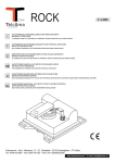
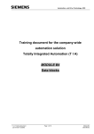
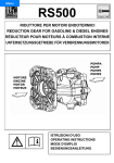
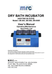
165 Electronics Blvd., Huntsville, AL 35824
Telephone: (256) 721-9090 • FAX (256) 721-9091 • Call Toll Free: 1-800-253-2583
REV 10/14
SAFETY PRECAUTIONS
• Equipment should be operated only by trained, responsible people.
• A careful operator is the best insurance against an accident.
• Fill system with WATER first and check output.
• Check all valves, fittings, hose clamps, etc. for tightness and soundness before admitting fluid to system.
• Replace hoses when worn, cracked or if leaking.
WARNING: USE OF THIS PRODUCT FOR ANY PURPOSES OTHER THAN ITS ORIGINAL INTENT,
ABUSE OF THE PRODUCT, AND/OR MODIFICATION TO THE ORIGINAL PRODUCT IS STRICTLY
PROHIBITED BY CDS-JOHN BLUE COMPANY. CDS-JOHN BLUE COMPANY RESERVES THE RIGHT
TO DENY WARRANTY OR LIABILITY CLAIMS IN ANY/ALL SITUATIONS INVOLVING MISUSE, ABUSE
OR MODIFICATION.
THE ORIGINAL INTENT OF THIS PRODUCT DOES NOT INCLUDE USE WHERE THE MAXIMUM
ALLOWED SPEED, PRESSURE, OR TEMPERATURE IS EXCEEDED, AND IT DOES NOT INCLUDE
APPLICATION UTILIZING FLUIDS THAT ARE NOT COMPATIBLE WITH THE PRODUCT’S COMPONENT
MATERIALS. DO NOT USE THIS PRODUCT WITH FLAMMABLE OR COMBUSTIBLE FLUIDS SUCH AS
GASOLINE, KEROSENE, DIESEL, ETC.…, AND DO NOT USE IN EXPLOSIVE ATMOSPHERES. FAILURE
TO FOLLOW THIS NOTICE MAY RESULT IN SERIOUS INJURY AND/OR PROPERTY DAMAGE AND
WILL VOICE THE PRODUCT WARRANTY. IF IN DOUBT ABOUT YOUR APPLICATION, CONTACT YOUR
STOCKING DEALER OR THE CDS-JOHN BLUE TECHNICAL STAFF AT 1-800-253-2583.
BE CAREFUL! REMEMBER, SAFETY IS NO ACCIDENT
TO THE OWNER
This manual has been prepared and illustrated to assist you in the maintenance of
your CDS-JOHN BLUE PUMP.
Enter your serial number and date of purchase in the space provided below for future
reference in service information or for ordering parts.
Because our engineering department is constantly improving products, we reserve
the right to make design and specification changes without notice.
Serial No.
Purchase Date
1
INSTALLATION AND GENERAL SAFETY INFORMATION
1) Always mount pump with oil sight tube in upright position.
2) Proper selection of type and size hose is vital to good performance:
-Diameter of inlet hose should be at least that of the pump inlet hose barb or greater.
-Use only hoses rated for maximum pressure rating of the pump.
3) Use of a pressure relief device on the discharge side of pump is required to prevent damage from pressure
build up if the discharge is closed or blocked while the power source is still running.
4) Install one or more suitably sized strainers (at least one and a half times flowrate) on the pump supply.
The filtering service should be dimensioned as required.
INSTALLATION DIAGRAMS OF THE PUMP
5) Do not operate pump above 145ºF (62ºC) liquid temperature.
6) Provide adequate protection by placing guards around the moving parts such as the shaft and pulleys.
7) Attach the pump to a strong base plate and anchor it with bolts sufficiently strong to hold it in place.
8) Periodically inspect the pump and the system components. Perform routine maintenance as required (see
Maintenance section).
9) Wiring an electrically driven pump, follow all electrical and safety regulations.
10) If the pump is driven by a gasoline engine, make sure that the area is well ventilated.
Checks to make before using the pump
-With the pump not running, check to make sure that the oil level is correct. Repeat with the pump running.
OIL LEVEL USED ON 2 DIAPHRAGM PUMPS
OIL LEVEL USED ON 2 DIAPHRAGM PUMPS
2
-Check to make sure that the inlet, discharge and by-pass hoses have the correct diameter, i.e. never smaller than
the union on the pump. The hoses should not be crimped and the hose clamps should be sized for hose diameter.
-Prevent any hose restrictions and be sure connections are tight to prevent air entering, since these conditions will
compromise pump performance.
-If pumping from a tank, check to make sure that the control unit by-pass line is not too close to the inlet line. Make
sure that it does not create turbulence inside the tank.
-Check air pressure in the pulsation damper. It should be kept within specs given in the Chart on the Service Manual.
-The pressure regulator lever should be turned downward. Whenever the by-pass jet is used, the pressure
adjustment lever must be turned in the down position so that the pressure is zero.
-Check to make sure the strainer is clean. Be sure the cartridge is reinstalled and tightened to assure no suction
leak.
-Check for leaks.
Suction Head
Do not use suction head for filling the tank. Avoid suction head higher than 10 feet.
In this case, some troubles may occur in the pump parts.
Operation Instructions
-Start pump and let run for approximately one minute at zero pressure to facilitate priming. Once primed, the pump
is ready and can be set to run at the desired pressure by moving the lever downwards and turning the adjustment
knob clockwise.
-Operating pump above recommended rpm will not improve performance but rather may damage the pump.
Operation at rpm higher than specifications voids all warranties.
-Working pressure should be selected with the discharge line closed and all liquid in by-pass.
-While the pump is running, check the oil level in sight glass. This acts as an emergency indicator to signal
malfunction, e.g. if the diaphragm breaks, the oil will become white. Stop the pump immediately.
-Do not rotate the shaft for long periods without liquid in the cylinders or in the suction line.
-If the pump is driven by a PTO shaft and sprayer makes a sharp turn, disconnect the tractor PTO to prevent damage
to the shaft supports and to the crankcase.
-If oil volume increases due to high operating temperature and the oil reaches the level of the plug, stop the pump to
prevent damage from internal overpressure.
After Use
After use, in order to prevent damage, flush pump and let operate for a few minutes at working pressure with
a solution that will neutralize the liquid last pumped (refer to that manufacturer’s instructions). Afterward empty the
pump, so that the pressure drops to zero (“0”), and then let the pump run without liquids for two minutes.
To protect pump from freezing, flush pump per instructions above (after use) and then flush with straight
RV-antifreeze. Empty the pump per the instructions above.
Ordinary Maintenance
Change oil every 500 hours as follows:
-Remove cap from oil sight tube and drain plug.
-Turn pump upside down and rotate the shaft by hand until oil stops flowing out.
-It is recommended to make an inside washing with gasoline or diesel oil.
-Put the drain plug back and pour oil into sight tube while turning the pump shaft. Be sure oil is at the indicated level
and care not to exceed it.
-Start the pump at pressure “0” for a few minutes to allow the correct lubrication of inside parts, then check oil level.
3
Coupling to Agricultural Machinery
1) Check that the PTO of the machine does not exceed the max rpm shown on the pump plate.
2) If the PTO is synchronized with the motor speed, consult the service manual to get gear number and rpm
corresponding to the max pump rotation speed.
3) When the rpm of the PTO is higher than the max speed, use the suggested reduction gear.
4) Disconnect the PTO when moving with pump out of service; if that is impossible, then disengagement should
be provided.
5) Disconnect the PTO when changing direction.
Coupling to electric motors and gasoline engines
1)
For direct coupling always use the suggested reduction gear.
2)
For coupling with pulley, check alignment of the two pulleys.
Maximum Transmission Ratio:
Motor RPM
Pump RPM
=K
After determining K, you can establish the motor or pump pulley diam.:
Pump Pulley Pitch Diameter = K
Motor Pulley Pitch Diam.: m.p.ø =
K
Pump Pulley Pitch Diam. - p.o.ø = Motor Pulley Pitch ø x K
MAINTENANCE FOR DIAPHRAGM PUMPS
Routine maintenance on the pump includes changing the diaphragms, oil, valve assembly, o-rings, all of which are
normal wear parts.
1)Valve assembly and O-Rings Replacement
Occasionally debris can cause the valves to not seat properly or damage o-rings. To check for this problem please
follow these steps:
-
Remove the valve cover (consult the exploded drawing of the pump), remove the valves, check for debris and
wear as well as o-rings.
-
Replace necessary parts and reassemble.
-
Repeat for all valves. Consult the parts list for the valve kit or o-ring kit part numbers.
4
2)Diaphragm Replacement
- Drain the oil from the pump by removing cap under the crankcase. Rotate the shaft to remove excess oil.
- Remove the pump heads one by one.
- Use a hex wrench to remove the diaphragm locknut: remove the nut, retaining washer, diaphragm and support
washer.
- If you removed the piston sleeves, replace them one at a time in their previous position (best mark them when
removing).
- Insert the new diaphragm on the piston and install it with its nut. Use these tightening torques.
• 10 mm.=36 ft.-lbs.
• 12 mm.=50 ft.-lbs.
• 12 mm.=72 ft.-lbs.
The diaphragms should be replaced with the piston at its bottom DP and the edges inserted perfectly into the groove
all the way around.
- Replace the heads and attach them with their bolts.
- Refill pump with oil through the glass and rotate the shaft to distribute oil and fill to proper level. Repeat all the
checks described above in the section “Checks to make before using the pump.”
- Check oil level with the pump running with no pressure until all air bubbles have been vented.
- When the air has been bled off, close the cap on the oil sight tube.
- After the first inspection of the oil level as above, check once more the oil level with the pump running with pressure.
3)Oil Change
Normally the oil is changed whenever the diaphragm is changed. Depending on work conditions, oil should be
changed every 500 hours.
The oil change procedure is described in number 2 above.
✮ FOR TROUBLESHOOTING CHART, SEE BACK COVER ✮
5
DP-74.1 And DP-74.1-GRI
PUMP DIMENSIONS
6
7
OPTIONAL
61
46
15
21
40
48 49
OPTIONAL
47
DP-74.1
DP-74.1 & DP-74.1-GRI
POS PART NO.
DESCRIPTION
QTYPOS PART NO.
DESCRIPTION
QTY
1 DP-03004031 PISTON DIAPHRAGM
3
27 DP-03001161 SPACER
1
1 DP-03004000 DESMOPAN PISTON DIAPHRAGM
3
28 DP-94004776 CONROD RING
2
1 DP-03004036 HPS PISTON DIAPHRAGM
3
29 DP-03001261 SPACER
1
■ 2 DP-03982197 VALVE ASSY.
6
30 DP-80133100 SHAFT RING D.45
1
3 31 DP-03000509 CONROD
3
■*4 DP-03002936 VALVE SEAL
6
32 DP-03000609 PISTON
3
5 DP-80321800 O-RING 3.0X22
1
33 DP-81850250 PISTON RING
6
6 DP-31151509 OUTLET FLANGE G.1/2
1
34 DP-85200600 PISTON PIN
3
7 DP-31151761 FLANGE
1
35 DP-80000300 RING DIA. 10
6
8 DP-03000309 SUCTION COVER
1
36 DP-86318500 SCREW M10X16
4
9 DP-86213100 SCREW M6X18
3
37 DP-17001361 COVER
1
3DP-03020209HEAD
*10 DP-80321066 O-RING 2, 62X101,27
1 *38 DP-80226410 OIL SEAL
1
*11 DP-80320830 O-RING 2, 62X36,14
1
39 DP-03001561 SPACER
1
12 DP-03000109 CRANKCASE
1
40 DP-03001726 CRANKSHAFT “VF” VERSION
1
13 DP-86290000 SCREW M8X55
4
40 DP-03003826 CRANKSHAFT “RT2” VERSION
1
14 DP-03001461 MOUNTING RAIL
2
41 DP-81293300 BALL BEARING DIA. 45X75X16
1
15 DP-80320000 O-Ring 2,62X22,22
1
42 DP-03000701 PISTON SLEEVE VERS. “VF” & “VC”
3
16 DP-84054200 90 DEG. ELBOW CONNECTOR
1
42 DP-03003601 PISTON SLEEVE VERS. “RT2”
3
17 DP-82004900 WING NUT M34
1
43 DP-86289300 SCREW M8X50
11
18 DP-83506210 NIPPLES G.3/4-M34
1
44 DP-03002197 KIT DIAPHRAGM WASHER/SCREW
3
19 DP-03001631 VALVE SEAL
1
46 DP-24304097 SAFETY VALVE 40BAR (OPT)
1
20 DP-86273000 SCREW M8X30
2
47 DP-31148232 PLAIN SAFETY CONE (OPT)
2
21 DP-84368500 WASHER DIA. 8,4X15X1,5
2
48 DP-84381000 WASHER (OPT)
4
22 DP-23000832 OIL FILLER
1
49 DP-86321200 SCREW M10X20 (OPT)
4
23 DP-80318000 O-RING 2,62X15,08
1
61 DP-84358500 WASHER 2
24 DP-85275000 OIL FILLER CAP
1
62 DP-86210800 SCREW M6X16 2
25 DP-82412000 GASKET DIA. 45X9X1.5
1
63 DP-31891697 KIT
1
26 DP-81264600 BALL BEARING DIA. 20X52X15
1
*PUMP KIT ORDER DP-03987497
■VALVE KIT ORDER DP-03987597
8
DP-74.1-GRI
PARTS LIST
FOR DP-74.1-GRI
ITEM
2
3
4
5
6
7
8
9
11
12
14
15
16
17
18
PART
NUMBER
DP-80212600
DP-80212650
DP-80643600
DP-31079542
DP-81264600
PP-85351100
DP-85350500
DP-86256600
DP-85351100
DP-86321200
DP-31128409
DP-31191409
DP-86256900
DP-31072942
DP-80308090
DP-80318700
DP-82414100
DP-85262953
DP-85263200
DP-31128509
DESCRIPTION
O-RING 30X60X10
KEY
PINION GEAR
BALL BEARING
OIL SIGHT GLASS
SCREW 5/16
FILLER PLUG
SCREW M10X20
GEAR BOX
SELF LOCKING SCREW
GEAR
O-RING 1,78X82, 27
GASKET
PLUG G 1/2
CENTERING FLANGE ENGINE/GEAR BOX
9
QTY.
1
1
1
1
1
4
1
4
1
3
1
1
1
1
1
DP-90.1 And DP-90.1-GRI
PUMP DIMENSIONS
10
11
OPTIONAL
46
61
15
48 49
OPTIONAL
47
DP-90.1
DP-90.1 & DP-90.1-GRI
POS PART NO.
DESCRIPTION
1 DP-03004031 PISTON DIAPHRAGM
QTY POS PART NO.
QTY
26 DP-81264600 BALL BEARING
1
1 DP-03004000 DESMOPAN PISTON DIAPHRAGM 3
27 DP-03001161 SPACER
1
1 DP-03004036 HPS PISTON DIAPHRAGM
3
28 DP-94004776 CONROD RING
2
■ 2 DP-03982197 VALVE ASSY.
6
29 DP-03001261 SPACER
1
3
30 DP-80133100 SHAFT RING
1
■*4 DP-03002936 VALVE SEAL
6
31 DP-03000509 CONNECTING ROD
3
5 DP-80321800 O-RING 3,0X22
1
32 DP-03000609 PISTON
3
6 DP-31151509 OUTLET FLANGE G.1/2
1
33 DP-81850250 PISTON RING
6
7 DP-31151761 FLANGE
1
34 DP-85200600 PISTON PIN
3
8 DP-03000309 SUCTION COVER
1
35 DP-80000300 RING
6
9 DP-86213100 SCREW M6X18
3
36 DP-86318500 SCREW M10X16
4
*10 DP-80321066 O-RING
1
37 DP-17001361 COVER
1
*11 DP-80320830 O-RING 1
*38 DP-80226410 OIL SEAL
1
12 DP-03000109 CRANKCASE
1
39 DP-03001561 SPACER
1
13 DP-86290000 SCREW V8X55
4
40 DP-03001826 CRANKSHAFT “VF” VERSION
1
14 DP-03003361 MOUNTING RAIL
2
41 DP-81293300 BALL BEARING 1
15 DP-80320000 O-RING
1
42 DP-03000801 PISTON SLEEVE 3
16 DP-84054200 90 DEG. ELBOW CONNECTOR
1
43 DP-86289300 SCREW M8X50
11
17 DP-82004900 WING NUT M34
1
44 DP-03002197 DIAPHRAGM WASHER/SCREW KIT 3
18 DP-83506210 NIPPLES
1
46 DP-24304097 SAFETY VALVE (OPT)
1
19 DP-03001631 VALVE SEAL
1
47 DP-31148232 PLAIN SAFETY CONE (OPT)
1
20 DP-86273000 SCREW M8X30
2
48 DP-84381000 WASHER (OPT)
4
21 DP-84368500 WASHER
2
49 DP-86321200 SCREW (OPT)
4
22 DP-23000832 OIL FILLER
1
61 DP-84358500 WASHER 2
23 DP-80318000 O-RING
1
62 DP-86210800 SCREW M6X16 2
24 DP-85275000 OIL FILLER CAP
1
63 DP-31891697 KIT
1
25DP-82412000GASKET
1
3 DP-03020209 HEAD
3
DESCRIPTION
*
PUMP KIT ORDER DP-03987497
■
VALVE KIT ORDER DP-03987597
12
DP-90.1-GRI
PARTS LIST
FOR DP-90.1-GRI
ITEM
2
3
4
5
6
7
8
9
11
12
14
15
16
17
18
PART
NUMBER
DP-80212650
DP-80212600
DP-80643600
DP-31079542
DP-81261600
PP-85351100
DP-85350500
DP-86256600
DP-85351100
DP-86321200
DP-31128409
DP-31191409
DP-86256900
DP-31072942
DP-80308090
DP-82414100
DP-80318700
DP-85262953
DP-85263200
DP-31128509
DESCRIPTION
O-RING 30X60X10
KEY
PINION GEAR
BALL BEARING
OIL SIGHT GLASS
SCREW 5/16
FILLER PLUG
SCREW M10X20
GEAR BOX
SELF LOCKING SCREW
GEAR
O-RING 1,78X82, 27
GASKET
PLUG G 1/2
CENTERING FLANGE ENGINE/GEAR BOX
13
QTY.
1
1
1
1
1
4
1
4
1
3
1
1
1
1
1
SC-1132-2 Pressure Regulator, 2 Outlets
_______________________________________________________________________________
ITEM
PART NUMBER
DESCRIPTION
QTY
_______________________________________________________________________________
1
SC-24031032
VALVE HOUSING
1
_______________________________________________________________________________
2
SC-83008000
PRESSURE GAUGE 0-100 BAR1
_______________________________________________________________________________
2
SC-83001000
PRESSURE GAUGE 0-24 BAR
1
_______________________________________________________________________________
3
SC-80306000
O-RING
1
_______________________________________________________________________________
4
SC-84052100
90 DEGREE ELBOW CONN.
1
_______________________________________________________________________________
5
SC-82004210
WING NUT
1
_______________________________________________________________________________
6
DP-84554410
LEFT TAP
1
_______________________________________________________________________________
7
SC-84154400
OUTLET STRAIGHT PORT
2
_______________________________________________________________________________
8
DP-82001000
WING NUT
2
_______________________________________________________________________________
9
DP-84554400
RIGHT TAP
1
_______________________________________________________________________________
10
DP-85258500
CAP
1
_______________________________________________________________________________
11
DP-84358500
WASHER
2
SC-86241400
_______________________________________________________________________________
12
SC-85242600
SCREW
2
SC-81452500
_______________________________________________________________________________
13
SC-81152500
NUT
4
_______________________________________________________________________________
14
DP-80321800
O-RING
1
_______________________________________________________________________________
15
SC-80305900
O-RING
1
_______________________________________________________________________________
16
SC-24032051
VALVE SEAT
1
_______________________________________________________________________________
17
SC-86184150
SCREW
1
_______________________________________________________________________________
18
SC-24031951
POPPET
1
_______________________________________________________________________________
19
SC-24031336
HPS DIAPHRAGM
1
_______________________________________________________________________________
20
DP-84353900
WASHER
4
_______________________________________________________________________________
21
SC-86194420
SCREW
4
_______________________________________________________________________________
22
SC-24031132
FLANGE
1
_______________________________________________________________________________
23
SC-80307500
O-RING
1
_______________________________________________________________________________
24
SC-80317500
O-RING
1
_______________________________________________________________________________
25
SC-85114800
PIN
1
_______________________________________________________________________________
26
SC-24031453
GUIDING PISTON
1
_______________________________________________________________________________
27
SC-24031232
LEVER
1
_______________________________________________________________________________
28
SC-24031648
SPRING 40 BAR
1
_______________________________________________________________________________
28
SC-24055048
SPRING 15 BAR
1
29
SC-24032132
KNOB
1
14
DIVISION OF ADVANCED SYSTEMS TECHNOLOGY, INC.
DIVISION
OF ADVANCED
SYSTEMSAlabama
TECHNOLOGY,
290 Pinehurst
Drive • Huntsville,
35806 INC.
165
Huntsville,
AL 35824
P.O. Electronics
Box 1607 • Blvd.,
Huntsville,
Alabama
35807
Telephone: (256) 721-9090 • Fax (256) 721-9091
Call Toll Free: 1-800-253-2583
TROUBLES AND CURES
TROUBLESCAUSES
CURES
The pump doesn’t reach the
required pressure
•
•
•
•
The pressure gauge fluctuates
• pump is sucking air, or air hasn’t been evacuated completely
• valves blocked
• start pump with the gun open, to evacuate
the air and commutate
• clean and change valves
The liquid flow is irregular
• the air in the pulsation-damper is incorrectly set
• check pressure in pulsation damper (see
chart)
Output drops and the pump is
noisy
• oil level is too low
• top up with oil to correct level (halfway of
the sump), when pump is operating
Oil comes out of the discharge
pipe
• one or more diaphragms are broken
• Drain the pump of oil. Dismantle the head
and change diaphragms. Fill to the correct
oil level.
Oil is changing color into white
• Diaphragm failures. Stop pump immediately.
• Drain the pump of oil. Dismantle the head
and change diaphragms. Fill to the correct
oil level.
valves have worn seats
suction hose with air pockets or irregular elbows
worn nozzles or with wrong diameter
(see chart)
Clogged strainer
•
•
•
•
check valves
check hoses
check nozzles
clean strainer
THIS WARRANTY IS IN LIEU OF ALL OTHER WRITTEN OR EXPRESS WARRANTIES AND REPRESENTATIONS. ANY IMPLIED WARRANTIES INCLUDING MERCHANTABILITY OR FITNESS FOR ANY PARTICULAR
PURPOSE ARE EXPRESSLY LIMITED TO THIS WRITTEN WARRANTY. CDS-JOHN BLUE COMPANY SHALL
NOT BE LIABLE FOR CONSEQUENTIAL DAMAGES.
Use of this product for any purpose other than its original intent, abuse of the product, and/or any modification to the
original product is strictly prohibited by the manufacturer, CDS-John Blue Company. Any modification to the product
should be approved by CDS-John Blue Company prior to use. CDS-John Blue Company will deny Warranty claims and
liability in any situation involving misuse, abuse or modification.
Each new machine or component manufactured by CDS-John Blue Company through original buyer is warranted by
CDS-John Blue Company to buyer and to any party or parties to whom buyer may resell, lease or lend the equipment to be
free from defects in material and workmanship under normal use and service. This obligation of CDS-John Blue Company
under this warranty is limited to the repair or replacement of defective parts or correction of improper workmanship of
any parts of such equipment which shall within one year from the date of CDS-John Blue’s original delivery thereof, be
returned to CDS-John Blue’s factory, transportation charges prepaid and which CDS-John Blue Company shall determine
to its satisfaction upon examination thereof to have been thus defective. When it is impractical to return the defective parts
of such equipment to CDS-John Blue’s factory, then CDS-John Blue shall have no liability for the labor cost involved in
repairing or replacing any such parts and shall be liable solely for supplying the material necessary to replace or repair the
defective parts, provided that prior thereto CDS-John Blue Company shall have determined to its satisfaction that any such
parts are thus defective.
This warranty shall not apply to any equipment which shall have been repaired or altered outside CDS-John Blue’s factory
in any way so as to affect its durability, nor which has been subjected to misuse, abuse, negligence or accident, or operated
in any manner other than in accordance with operating instructions provided by CDS-John Blue Company. This warranty
does not extend to repairs made necessary by the use of inferior or unsuitable parts or accessories, or parts or accessories not
recommended by CDS-John Blue Company.
CDS-John Blue Company makes no warranties in respect to parts, accessories or components not manufactured by
CDS-John Blue Company, same ordinarily being warranted separately by their respective manufacturers.
DIVISION OF ADVANCED SYSTEMS TECHNOLOGIES
HUNTSVILLE, AL(256) 721-9090
15