1
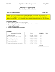
ECE 477 Digital Systems Senior Design Project Fall 2005 Homework 12: Ethical and Environmental Impact Analysis Due: Thursday, November 17, at Classtime Team Code Name: _____Backseat Driver________________________ Group No. ___11_ Team Member Completing This Homework: _________Jeffrey Lee____________________ NOTE: This is the last in a series of four “professional component” homework assignments, each of which is to be completed by one team member. The completed homework will count for 10% of the team member’s individual grade. It should be a minimum of five printed pages. Report Outline: Introduction (brief description of design project, with a focus on ethical/environmental issues related to your product’s life-cycle) Ethical impact analysis o Outline the ethical challenges your team would have to resolve in the process of bringing your design to market (testing under a variety of operating conditions, placement of warning labels, providing cautions in user documentation, adding safety mechanisms). o Discuss how you would address each of the ethical challenges outlined above. Environmental impact analysis o Outline the environment impact of your product at various stages of its life cycle (manufacture, normal use, disposal/recycling) – e.g., any product using rechargeable batteries represents a potential environmental hazard, any product with a printed circuit board contains lead. o Discuss how you would address each of the environmental impact concerns outlined above (e.g., provide explicit means/process for recycling hazardous materials). List of references (spend a significant amount of time on this – see articles provided on the course web site) Evaluation: Component/Criterion Score Multiplier Introduction 0 1 2 3 4 5 6 7 8 9 10 X1 Ethical Impact Analysis 0 1 2 3 4 5 6 7 8 9 10 X3 Environmental Impact Analysis 0 1 2 3 4 5 6 7 8 9 10 X3 List of References 0 1 2 3 4 5 6 7 8 9 10 X2 Technical Writing Style 0 1 2 3 4 5 6 7 8 9 10 X1 TOTAL Include this sheet as a cover page for your report Points ECE 477 Digital Systems Senior Design Project Fall 2005 I. Introduction The “Back Seat Driver” project is a vehicle lane detection warning system which will also detect obstacles in the lane to ensure the safety of the driver. First the device takes image input from a black and white CCD camera, and the tilt sensors. Afterward, the microprocessor will analyze the digitized image, compute the position, and send both visual and audio outputs to warn the vehicle driver. The entire system will be encased in a box except the camera which will be mounted to the sun visor. The environmental issues related to the Back Seat Driver are fairly minimal during its lifetime. Back Seat driver will not emit any pollution into the atmosphere at all and the heat dissipation from the various electrical sources will be too little to cause any noticeable concern. The only environmental issue that will arise will be upon the completion of the life-cycle of the product, when it is discarded. The internal components of the Back Seat Driver are nonbiodegradable and hence would need to be dealt with appropriately. The ethical concerns will be more challenging as the Back Seat Driver will have some critical safety issues during both the test period and the time consumers will be using it. Dealing with any potential shocks relating to the power supply are also ethical concerns that we have considered. II. Ethical Impact Analysis A. Possible Problems Testing under a variety of conditions will pose serious safety risks both to the tester and other people. To test the product, rapid lane change procedures in a variety of weather and road conditions without using a turn signal will be required. In the extreme case this could lead to the death of the tester and others. Another serious safety concern is if the user becomes overly reliant on the device. The product will not successfully detect every hazardous situation so if the user becomes reliant on a ECE 477 Digital Systems Senior Design Project Fall 2005 warning and the product fails there could be serious injury or even death. The product could actually contribute to the exact problem it is trying to prevent. Connected to this, there are potential failures of the system that cannot be detected so the user may believe that the device is operating properly when it is actually not. The packaging of the product was not able to prevent user to temper the product. By tempering the product, user risked themselves to injury either by electric shock or burn. The packaging was not water-proof because of the cooling method requires exchanges between cool outside air and hot inside air. This can lead to possible electric shock if water leakage. A. Solutions Testing safety can be improved by controlling the test environment. Most of the functionality can be tested in a parking lot with a few lanes painted on it. During actual road tests, a three person testing method would be adopted. The first person would sit in the passenger seat and would be in charge of safety. He would monitor the position of nearby vehicles and would have final authority on which tests were performed and when. He would communicate the test instructions to the driver. The second person, the driver, would follow the directions of the safety person and would be focused entirely on driving. The third person would monitor the product and record data on its performance. He should not communicate any information about the product to the others during the test in order to limit distractions. For obstacle detection testing, two vehicles will be used. The forward vehicle will have only the safety person and driver and will be the obstacle. The rear vehicle will have all three people. The two safety people will communicate via walkie talkie to coordinate the test. In general, road testing will be performed as much as possible during quiet traffic conditions. Other than those test mention above, this device will also undergo Federal Communication Commissions (FCC) compliance test [1]. ECE 477 Digital Systems Senior Design Project Fall 2005 To overcome the driver’s growing reliance on the product, a warning label will be used to warn the user. The warning label will have orange background similar as ANSI standard in figure 1 with a readable font size, and will be printed at the front side of the product so that the driver can notice that. The warning label should mention something similar to “The use of this device will not prevent collisions which could result in serious injury or death. User should always maintain vigilance while operating the vehicle”. Figure 1. American National Standard Institute (ANSI) warning label[2] For the packaging problem, a warning label will also be used to stop users from tampering with the device. In order to get user’s attention before opening the box, this label will be placed at the bottom of the box and it will have orange background with a readable font size. To reduce installation error, an installation procedure including the operating voltage and temperature will be printed at the bottom of the box. In addition, a detailed user manual will be provided that pictorially shows the user how to install the device and includes some possible troubleshooting tips related to the installation procedure. I. Environmental Impact Analysis A. Manufacturing The manufacturing process for electronic circuits itself is quite polluting. For example, the manufacturing process for PCBs is quite toxic in the amount of waste and pollutants generated involves the use of multiple steps where PCB boards may be subject to: solder stripping, etching, surface conditioning, copper plating, and cleaning using chemicals, acid baths, ECE 477 Digital Systems Senior Design Project Fall 2005 and other potential pollutants [3, 4]. In addition, in order to maintain product quality, manufactures may often choose to dump chemical baths regularly or use high flow rinsing systems between chemical baths. This is process in itself is unavoidable since we subcontract our PCBs out to other companies for manufacture. However, there are some ways in which we can improve the environmental impact of our PCB design. First of all, the PCB design will be kept to a minimal number of layers (preferably 2 layers). Also, the use of more copper planes over lone traces will also help reduce the amount of copper needed to be etched away, allowing the acid baths to be used for a longer time. This will reduce the number of acid baths required for washing off copper layers. Due to the fact that this device is not considered very high performance, intensive cleaning of non-corrosive flux is not required [5]. The manufacture of discrete components itself is also quite demanding in terms of the chemicals involved. In addition to the poisonous dopants such as arsenic, boron, antimony and phosphorus, compounds such as arsine, phosphine, and silane are used [6, 7]. Hydrogen peroxide, nitric acid, hydrochloric acid, and hydrofluoric acid are common liquids used for washing and etching semiconductor wafers. Those all contribute to pollution in the fabrication process. Due to those concerns, one possible way to minimize this impact on the environment is to select simpler chips for less crucial functions. Chips that are simpler can be made in a lesser number of steps, thus saving not only on cost but also amount of material put into the fabrication the semiconductor die. Lastly, for mounting the surface mount parts on the PCB, the choice of using infrared reflow or nitrogen gas based vapor phase reflow process in the solder reflow oven is more environmental [5] than using fluorocarbon based vapor phase reflow. ECE 477 Digital Systems Senior Design Project Fall 2005 B. Normal Use For the normal usage, the environmental impact will be minimal. This device does not emit any hazardous waste. This device is not battery-powered, so exclude the possible hazardous waste from batteries. C. Disposal/Recycling Electronic waste, also known as e-waste, is one of the fastest growing problems in pollution today. As of year 2000, the amount of waste generated in the United States per capita is 7.33 kg/person [8]. E-waste management is important for environmental protection due to the toxic materials present in many electronic devices today. Those materials include lead, cadmium, and mercury, among many others [9]. Our device is primarily a large single PCB with electronic components mounted on it. The only other major components will be the housing for the electronic device, the camera, and the power supply jack. Some major toxic substances present in the device include halogenated compounds, arsenic, and lead [8]. Other substances that make up our device may include: plastics, aluminum, germanium, gallium, iron, tin, copper, nickel, zinc, tantalum, indium, terbium, beryllium, gold, europium, ruthenium, cobalt, palladium, manganese, silver, antinomy, bismuth, cadmium, selenium, rhodium, platinum, mercury, and silica. Out of these materials, iron, aluminum, copper, gold, plastic, zinc, and lead are the most commonly recycled substances. Possible methods of disposal include incineration, open burning, landfilling, and recycling. Due to the environmental unsustainability of the former three methods, recycling our product after its end-of-life is the wisest choice. However, recycling should be subcontracted to known and well trusted organizations and/or companies. There are instances of electronic products recycled in third world countries or by unlicensed groups where environmental ECE 477 Digital Systems Senior Design Project Fall 2005 protection is overlooked in the pursuit of profits. Such environmental violations include the use of acid baths to extract gold [8], burning of cables to extract wiring, or the use of open flame or open molten lead baths to remove solder. Thus all potential contractors for e-waste processing will need be examined closely. In fact, it is not uncommon for American e-waste management companies to flout international laws and illegally send e-waste overseas to be processed [12]. In addition, recycling of e-waste is required by law in many industrialized countries and many U.S. States [10]. For example, the WEEE was established by the European Commission in order to address the problems with e-waste. With the lifespan of the average electronic device dropping down to an average of 2-4 years [11], it is important for the electronics industry to embrace such environment standards for recycling and disposal of equipment. The typical process for recycling e-waste is as follows [9]. Often electrical components are divided into metal, plastic, and PCBs for shredding or recycling. Due to the fact that many plastics in electronic equipment may contain fire-retardant halogen compounds, the WEEE does not call for plastics to be recycled. Components in good condition may be reused, while remaining parts may be separated manually or be shredded and granulated to be screened and filtered out. In order to inform the user the necessity of recycling, the label: “WARNING: This device contains lead and other toxic substances. DO NOT DISPOSE NORMALLY! Follow the provided link for disposal instructions.” In addition to this message, a link to a webpage will be provided that would allow the user to find the nearest certified e-waste company in area for processing. Our company will have contracts with those companies to provide disposal free of charge to the customers. In order to reduce waste, good components may be recycled to be used in lower-end product lines after extensive testing. ECE 477 Digital Systems Senior Design Project Fall 2005 III. List of References [1] “Commission advances” Navigation Devices” rules creating consumer market for set top boxes: allows analog deferral,” FCC, http://www.fcc.gov/Bureaus/Cable/News_Releases/1999/nrcb9009.html [2] “ComplianceSigns-Home – OSHA and ANSI compliant safety signs,” Compliance Signs, http://www.compliancesigns.com/?engine=adwords!4851&keyword=%28safety+label% 29&match_type= [3] “Total Quality Management/Pollution Prevention Integration Study for the Printed Circuit Board Industry,” PRC Environmental Management, September 2, 1993, http://es.epa.gov/techinfo/facts/ca-htm/htmfct24.html#link7 [4] “Printed Circuit Board (PCB) Etching,” AirBorn Electronics, http://www.airborn.com.au/method/etch.html [5] “Printed circuit board,” Wikipedia, November 15, 2005, http://en.wikipedia.org/wiki/Printed_circuit_board [6] “Semiconductor fabrication,” Wikipedia, November 10, 2005, http://en.wikipedia.org/wiki/Semiconductor_fabrication [7] “Inside the Intel Manufacturing Process,” Intel, http://intel.com/education/makingchips/ [8] “Facts and Figures,” eWaste Guide, http://www.ewaste.ch/facts_and_figures/ [9] “E-waste,” Wikipeida, November 14, 2005, http://en.wikipedia.org/wiki/E-waste [10] “Directive 2002/96/EC,”Waste Electrical and Electronic Equipment, January 27, 2003, http://europa.eu.int/eur-lex/pri/en/oj/dat/2003/l_037/l_03720030213en00240038.pdf ECE 477 [11] Digital Systems Senior Design Project “Trends in Electronics Recycling in the United States,” National Recycling Coalition, November 3, 1999, http://www.nrc-recycle.org/resources/electronics/trends.htm [12] Fall 2005 “Does Your TV Recycler Really Recycle?” Robin Ingenthron, July 18, 2003, http://www.crra.com/ewaste/articles/tvrecycler.html