1
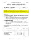
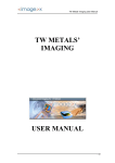
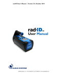
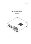
Pulse300
Xenon Flashlamp System
(designed for use with the Imagex Time-Gated Camera)
The Pulse300 Flashlamp System
Introduction
The Pulse300 flashlamp is designed to provide microsecond pulses of light across the
spectrum from ultraviolet to infrared. It is very simple to operate, requiring only a 24 volt DC
supply. The unit dissipates approximately 30 Watts. The flashlamp is operated by standard
TTL trigger pulses furnished to the BNC input socket. The maximum pulse rate is 300 Hz,
determined by the storage capacitor in the high voltage power supply.
The system is designed for time-gated detection of long-lived probes such as lanthanide
complexes e.g. Europium, Terbium.
The light pulses are about a microsecond long with a ‘tail’ (where the light is decaying away)
of up to 10 microseconds. The length of this tail is wavelength dependent and gets longer with
increasing wavelength.
The Pulse300 is specifically designed for use with the Imagex Time-Gated camera system
and can be driven with a standard TTL pulse. The pulse is triggered by a rising edge -:TTL
Low (0Volts) to TTL High (5 Volts) transition and this is supplied by the Lamp ports on the
Imagex controller unit.
Please read the Safety section at the end of this manual as it is very important to observe the
correct operational procedures when using the lamp.
Pulse300 Xenon Flashlamp System
Operation Manual Page 1
Description of Components
The Pulse300 system is powered by a 24volt switched mode power supply. You should not
use any other power supply unless you have consulted with Photonic Research Systems first.
Any attempt to use a power supply other than the one supplied with the system will invalidate
the warranty.
The Pulse300 is supplied in 4 parts:
A) The Mounting Plate-This is used to connect the system to a Nikon microscope.
B) The Extension Tube-This attaches to the mounting plates and accepts the flashlamp
housing. It allows the distance of the lamp from the microscope to be adjusted by the
user.
Pulse300 Xenon Flashlamp System
Operation Manual Page 2
C) The Lamp Housing & High Voltage Supply-This component consists of two parts
connected by a length of flexible conduit or pipe. The sections should never be separated
except by a qualified electrician. High voltages are present inside the power supply,
flashlamp head and conduit!
Please note that the Xenon flash lamp head is attached to the high voltage power
supply unit by a length of flexible conduit. The cables in the conduit carry high voltage
pulses and therefore you must not attempt to remove the head from this conduit.
The length of the cables in the conduit determines the pulse properties of the lamp.
Any attempt to change the length of this cable may result in a deterioration of
performance (pulse length and stability) and expose the user to high voltage hazards.
D) DC power supply-This takes mains (AC) electricity and produces a suitable DC voltage
to run the lamp power supply. Do not use an alternative power supply without
consulting Photonic Research Systems.
Pulse300 Xenon Flashlamp System
Operation Manual Page 3
Attaching the Pulse300 to a microscope
The Pulse300 is supplied with a mounting plate and extension tube to allow mounting of the
system onto a fluorescence microscope. The mounting plate is specific for a particular
microscope so it is important to ensure that this plate matches the specification of your
microscope lamp mount. If you are having difficulty mounting your lamp please contact
Photonic Research Systems.
Before connecting the Pulse300 system to the microscope please ensure that all power
supplies are switched OFF.
It is a good idea to have the correct tools. You may need the following:
1)
2)
3)
4)
5)
Screwdrivers
Pliers
A stand with adjustable height
An adjustable spanner
A set of Allan keys (hexagonal screwdrivers)
Please read the Safety section at the end of this manual as it is very important to observe the
correct operational procedures when using the lamp. You should wear safety glasses during
the mounting process and avoid touching the window of the flashlamp.
1) Attach the microscope mounting plate (A)
Once you have all the necessary tools you need to locate the microscope mounting plate
(shown earlier in the ‘Description of Components’ section).
This plate provides the interface between the microscope and the flashlamp head.
The position of the holes in the mounting plate depend on the microscope that the plate is
designed for, but the holes to use are usually located around the circular hole in the middle of
the plate. Use the correct screws to attach the plate to the microscope.
Pulse300 Xenon Flashlamp System
Operation Manual Page 4
Depending upon the geometry of the microscope it may also be necessary to insert M3
screws into the four corner holes as shown, before mounting the plate onto the microscope.
This is only required where the corner holes are obscured after attaching the mounting plate
to the microscope. (See the figure above)
2) Attach the extension tube (B)
If you have not yet done so you need to put M3 screws through the corner holes of the
mounting plate so that the thread is facing you.
Pulse300 Xenon Flashlamp System
Operation Manual Page 5
You may now place the extension tube plate against the mounting plate so that the screws
pass through both plates. Once you have done this you may now put M3 nuts onto each of
the corner screws to bolt the two plates together.
You should now have the extension tube attached to your microscope. The flashlamp head
can now be slid into the extension tube.
Pulse300 Xenon Flashlamp System
Operation Manual Page 6
Note: If you cannot access both ends of the corner screws that attach the extension tube to
the mounting plate it may be necessary to hold the end of the screws while tightening the nuts
with a spanner. Take care not to damage the thread of the screws whilst doing this.
3) Attach the Flashlamp head (C)
Once you have successfully mounted the extension tube you may now slide the flashlamp
head into the extension tube.
The extension tube has three screws which allow you to lock the position of the flashlamp
head in place. Do not overtighten these screws.
Pulse300 Xenon Flashlamp System
Operation Manual Page 7
4) Position the High Voltage Power supply correctly!
Once you have mounted the flashlamp head you must consider the position of the High
Voltage Power Supply that is attached to it. Please ensure that the conduit that connects the
flashlamp head to the High Voltage power supply is not put under stress. If the microscope
lamp port is high off the bench so that the High voltage power supply is not lying flat on the
ground you should support the High Voltage power supply with an appropriate stand as
shown below:
Note: It is not possible to extend the length of the conduit. This would prevent the
correct timing operation of the flashlamp
Pulse300 Xenon Flashlamp System
Operation Manual Page 8
Lamp Operation & Position Adjustment
In order to complete the setting up of your lamp with your microscope you will need to operate
the lamp. This will allow you to set the exact position of the lamp relative to the microscope
optics and optimise the illumination field.
To operate the lamp you should connect the Lamp Trigger Input to a 300Hz (three hundred
Hertz) TTL (0-5Volts) frequency source. This could be one of the Imagex lamp outputs or a
dedicated frequency generator, but please confirm that the frequency is set correctly to 300Hz
before proceeding.
Use a BNC-BNC cable to connect the lamp to the frequency source. Plug one end of the BNC
cable into the Lamp Trigger Input and the other end into the frequency source.
Now take the plug from the supplied DC power supplied and insert it into the DC Power Input
on the High voltage power supply.
Do not connect the DC power supply to the mains electrical supply at this point.
The lamp position can be adjusted in three dimensions, X (left-right), Y(up-down) and Z
(backwards-forwards). The backwards and forward positioning is performed by loosening the
holding screws around the circumference of the extension tube and sliding the flashlamp
head in or out. Retighten the screws once the correct position is obtained.
The up-down left and right positioning is achieved by loosening the four M3 corner nuts that
connect the extension tube to the microscope mounting plate (Note: do not remove the nuts
Pulse300 Xenon Flashlamp System
Operation Manual Page 9
just loosen them to allow the plates to move). You can then slide the two plates across each
other until the correct position is obtained. Retighten the nuts lock the plates together again.
Care of your System
Once fitted your lamp should not require any significant maintenance. If the lamp fails after its
normal operating lifetime you may replace it with an identical flashlamp bulb (Perkin Elmer
FX1164). Please follow the safety instructions on the final page whenever you handle the
flashlamp bulb. In particular:
Always wear eye and hand protection. The flashlamp bulb is pressurized
Ensure that the high voltage power supply is earthed
Remove the frequency source before removing installing lamps
Never handle or touch the flashlamp until it is cooled to room
temperature
Ensure that the power supply is switched OFF before
removing/installing lamps
Do not touch the window of the old or new bulb. Grease on the window
can cause it to fail under pressure
Insert the new flashlamp bulb in the same position as the old one
Do not use metallic gripping tools to remove the bulb from the housing
Pulse300 Xenon Flashlamp System
Operation Manual Page 10
Safety
It is important that you follow the correct safety procedures when
operating the Pulse300 lamp....
*
Do not attempt to trigger the lamp at >300Hz as this may damage the lamp.
*
In use an optical filter will normally be needed to select the wavelength range of
interest. Do not allow the filter to come into contact with the window of the flashlamp
or lamp failure is likely.
*
The Xenon lamp, like all arc sources should be handled with care as it is under
pressure.
*
Never attempt to remove a lamp until it has cooled to room temperature.
*
Never touch the front face of the lamp. Fingerprints may cause deterioration of the
optical window. If the window of the lamp has been inadvertently touched, wipe it
clean by carefully drawing a lens tissue moistened with ethanol across the face and
allow to dry in air before use.
*
If the lamp must be removed wear protective gloves and eye protection. Do not
subject the lamp to lateral forces or torque as this might break the ceramic seal.
*
The lamp operates at high voltage but the power supply and input BNC are
electrically isolated. Ensure that the outer casing of the lamp housing is properly
earthed at all times as this improves electrical shielding of emissions and is a further
safety precaution. An earth point connected to the housing is provided on the power
supply box in the form of a yellow connector.
*
Take care not to subject the armoured connection to the lamp to undue strain. The
short cable length is optimised to give fast optical pulses. Do not attempt to install a
longer connecting lead to the lamp.
*
The power supply unit for the lamp contains components operating at high voltage
which could be dangerous. Do not open the unit, even when the power supply is
switched off as the high voltage storage capacitor might still be energised in some
circumstances. Do not attempt to service this unit. In the event of a malfunction return
the unit to PRS for repair.
*
The light from the flashlamp is rich in short wavelength ultraviolet light which is
harmful to skin and eyes. Avoid exposure to emission from the unit and use eye
protection when operating the lamp.
*
Ensure that the lamp and power supply each has adequate ventilation at all times.
Pulse300 Xenon Flashlamp System
Operation Manual Page 11