1
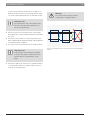
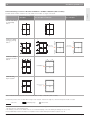
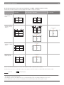
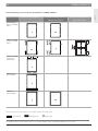
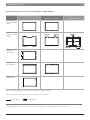
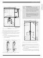
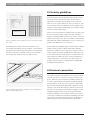
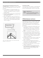
14 | Grounding | Maintenance and care en Please implement the following measures for the Functional grounding grounding system (you will find the respective mounting Isolated operation of the modules is recommended, this holes for the grounding system on the rear of the mod- means neither plus nor minus terminal of the module ule frame): have an electrically charged connection to the ground. For the installation of a fitting ring terminal, use a thread grooving screw (DIN7500-1, minimum diameter 5 mm), a self-cutting lock washer, a snap ring Important note! and the right nut. If a functional grounding is required, then this can only be undertaken on the Damaging contact corrosion can be avoided by using minus terminal in the PV system. corrosion-resistant materials. Position of the mounting holes for grounding according to Figures 2 and 4. There is an additional grounding opportunity in the module corners. Use the grounding of a thread grooving screw M5 according to DIN7500-1 and attach it from the rear side of the module behind the plastic 8 Maintenance and care corner. See Figure 7. Little maintenance and care is required to deliver optimum solar module performance. We recommend the following items are checked or the following action Rear view detailed drainage area with a grounding function taken on a half-yearly basis to ensure optimum system performance: If modules are heavily soiled or dirty in places, from bird droppings, for instance, it is recommended to clean module glass surfaces with a soft brush and lime-free water at module temperature. Do not use aggressive cleaning agents, acids or alkaline solutions. Under no circumstances should there be increased pressure during cleaning e.g. by pressing a brush so strongly during cleaning, that this can lead to damage to the antireflective coating of the glass for example. In the case of intensive soiling, repeated cleaning or soaking is recommended. Any finger prints on the anti-reflection solar glass can be removed with a microfiber cloth and distilled water or isopropanol. Figure 7: Grounding possibilities on the module with detailed illustration of module corner Check electrical and mechanical connections to ensure they are clean, tightly fastened and intact. Any anomalies must be remedied immediately. The operator is recommended to check the system's output on a regular basis. The grass and weeds in and around open ground area systems must be mowed regularly. This is necessary to minimize the potential hazard of organic material (e.g. dry grass, hay) combustion in the vicinity of the system. Bosch Solar Module c-Si M60+ S EU56117 I Bosch Solar Module c-Si M60+ EU56117 Bosch Solar Energ AG