1
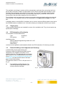
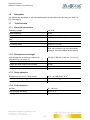
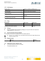
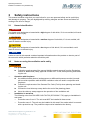
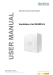
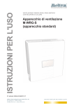
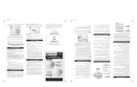
OPERATING INSTRUCTIONS
V E N T I L AT I O N & H E AT R E C O V E R Y
HOME VENTILATION WITH HEAT RECOVERY
M-WRG-S ventilation unit
(standard unit)
Part no. 5302-00-01 06/2015 EN
Meltem Wärmerückgewinnung GmbH & Co. KG
Am Hartholz 4 · D-82239 Alling
[email protected] · www.meltem.com
VENTI LATI O N TH E RI GH T WAY
Operating instructions
M-WRG-S ventilation unit (standard unit)
V E N T I L AT I O N & H E AT R E C O V E R Y
Contents
1Introduction ...................................................................................................................... 5
1.1
Notes on the operating instructions ................................................................................... 5
1.2Description ......................................................................................................................... 5
1.3
Target group ...................................................................................................................... 6
1.4
EC Declaration of Conformity ............................................................................................ 6
1.5
General building control approval (for Germany) .............................................................. 6
1.6Nameplate ......................................................................................................................... 7
1.7
Technical data .................................................................................................................... 7
1.7.1 Electrical connection .......................................................................................................... 7
1.7.2 Dimensions and weight ..................................................................................................... 7
1.7.3 Noise emission .................................................................................................................. 7
1.7.4 Unit properties ................................................................................................................... 7
1.7.5 Unit features ...................................................................................................................... 8
1.7.6Filter ................................................................................................................................... 8
1.8Storage .............................................................................................................................. 8
1.9
Environmentally-friendly disposal ...................................................................................... 8
1.10 Revision index ................................................................................................................... 8
1.11 Explanation of the symbols used ....................................................................................... 8
2
2.1
2.2
2.3
2.4
Safety instructions .......................................................................................................... 9
Hazard classification .......................................................................................................... 9
Notes on using the ventilation units safely ........................................................................ 9
Notes on using the ventilation units ................................................................................. 10
Intended use .................................................................................................................... 10
3
Warranty and liability ..................................................................................................... 11
3.1Warranty ........................................................................................................................... 11
3.2Liability .............................................................................................................................. 11
4Dimensions ..................................................................................................................... 11
5
5.1
5.1.1
5.1.2
5.1.3
5.2
5.2.1
5.2.2
Structure and function .................................................................................................. 12
Overview of the modules ................................................................................................. 12
Ventilation unit – cover attached ...................................................................................... 12
Ventilation unit – cover removed ..................................................................................... 12
Outer wall terminal ........................................................................................................... 12
Description of the functions ............................................................................................. 13
How the M-WRG ventilation unit works ........................................................................... 13
How the cross-flow plate heat exchanger works ............................................................. 14
6
Rules for correct usage ................................................................................................ 14
6.1General ............................................................................................................................ 14
6.2
Operation in high atmospheric humidity .......................................................................... 14
6.3
Operation at cold times of year ........................................................................................ 15
6.4Filter ................................................................................................................................. 15
7
Controls on the ventilation unit ................................................................................... 16
8
8.1
Starting up ...................................................................................................................... 16
Check ventilation unit before switching on for first time ................................................... 16
Meltem Wärmerückgewinnung GmbH & Co. KG
Am Hartholz 4 · D-82239 Alling
[email protected] · www.meltem.com
VENTI LATI O N TH E RI GH T WAY
-2-
Operating instructions
M-WRG-S ventilation unit (standard unit)
V E N T I L AT I O N & H E AT R E C O V E R Y
8.2
8.3
Switch on the ventilation unit ........................................................................................... 16
Check position of air flaps ............................................................................................... 17
9
9.1
9.2
Operating the ventilation unit ....................................................................................... 18
Set ventilation level on stepping switch ........................................................................... 18
Frost protection function .................................................................................................. 18
10
10.1
10.2
10.3
10.3.1
10.3.2
10.3.3
10.3.4
Filter maintenance ......................................................................................................... 19
Choice of filter .................................................................................................................. 19
Ordering filters ................................................................................................................. 19
Filter change .................................................................................................................... 19
Remove cover from ventilation unit ................................................................................. 20
Remove filter ................................................................................................................... 20
Insert new filters .............................................................................................................. 21
Attach cover to ventilation unit ......................................................................................... 21
11Cleaning ......................................................................................................................... 22
12Troubleshooting ............................................................................................................ 22
Meltem Wärmerückgewinnung GmbH & Co. KG
Am Hartholz 4 · D-82239 Alling
[email protected] · www.meltem.com
VENTI LATI O N TH E RI GH T WAY
-3-
Operating instructions
M-WRG-S ventilation unit (standard unit)
V E N T I L AT I O N & H E AT R E C O V E R Y
Meltem Wärmerückgewinnung GmbH & Co. KG
Am Hartholz 4 · D-82239 Alling
[email protected] · www.meltem.com
VENTI LATI O N TH E RI GH T WAY
-4-
Operating instructions
M-WRG-S ventilation unit (standard unit)
V E N T I L AT I O N & H E AT R E C O V E R Y
1
Introduction
1.1
Notes on the operating instructions
These original operating instructions contain important information that should be followed when
setting up and using the M-WRG-S ventilation unit.
►►
Read all the instructions carefully before starting up the ventilation unit to avoid possible
risks and mistakes.
►►
When assembly is complete, give these instructions to the home owner, caretaker or property manager.
►►
These instructions are part of the product. Keep the instructions in a safe place for future
reference.
WARNING
►►
►►
Follow ALL danger and warning instructions and notes on precautionary measures.
Read section „2 Safety instructions“ on page 9 carefully.
1.2
Description
These instructions describe how to set up and operate the decentralised ventilation unit M-WRG-S
(see Fig. 1).
Fig. 1: M-WRG-S ventilation unit
M-WRG-S stands for Meltem heat recovery standard unit. Home ventilation expertise extending
back over 30 years has been incorporated into this product from Meltem Wärmerückgewinnung.
Using windows for ventilation, particularly during periods of cold weather, is now a thing of the past.
Meltem Wärmerückgewinnung GmbH & Co. KG
Am Hartholz 4 · D-82239 Alling
[email protected] · www.meltem.com
VENTI LATI O N TH E RI GH T WAY
-5-
Operating instructions
M-WRG-S ventilation unit (standard unit)
V E N T I L AT I O N & H E AT R E C O V E R Y
This ventilation unit brings in outdoor air fully automatically, and heats it by recovering heat from
the air that is extracted. Outdoor air and extract air are routed in separate ducts through a crossflow plate heat exchanger (see section 5.2.2 on page 14). You save on heating costs, increase
your living comfort and are kind to the environment by reducing CO2 emissions. A filter also removes pollen, dust and other impurities from the outdoor air.
The ventilation units are designed for continuous operation and can be both surface-mounted and
flush-mounted. The ventilation units are low-maintenance, but regular filter changes are important.
A stepping switch on the M-WRG-S ventilation unit is used to set three different power levels and a
time-limited intensive ventilation level. It therefore allows you to adapt the air flow to your needs.
1.3
Target group
These operating instructions are intended for users of the ventilation unit. They do not require any
special prior knowledge.
1.4
EC Declaration of Conformity
The ventilation unit described below
Type:
M-WRG-S
Part number:
5010
manufactured by
Meltem Wärmerückgewinnung GmbH & Co. KG
Am Hartholz 4
82239 Alling
conforms to the regulations and standards listed in the EC Declaration of Conformity provided.
1.5
General building control approval (for Germany)
A valid building control approval from the
Deutsches Institut für Bautechnik (DIBt) must be
obtained for the ventilation unit before it is installed in Germany. This approval can be provided
upon request or can be downloaded from our website at www.meltem.com/waermerueckgewinnung/
downloads/ (see also the QR code on the back
page of these instructions).
The approval number is Z-51.3-138 (see item 1 in
Fig. 2).
►►
For installation outside Germany, the
national regulations applicable in your
country should be followed.
Fig. 2: Approval number and nameplate
Meltem Wärmerückgewinnung GmbH & Co. KG
Am Hartholz 4 · D-82239 Alling
[email protected] · www.meltem.com
VENTI LATI O N TH E RI GH T WAY
-6-
Operating instructions
M-WRG-S ventilation unit (standard unit)
V E N T I L AT I O N & H E AT R E C O V E R Y
1.6
Nameplate
You will find the nameplate on the intermediate plate on the inside of the housing (see item 2 in
Fig. 2 on page 6).
1.7
Technical data
1.7.1 Electrical connection
Operating voltage
Mains frequency
Power consumption
Power consumption in relation to the air volume
flow
Maximum current consumption
Connecting cable
IP rating
230 V AC
50 Hz
3.8 - 34 W
0.17 W/m3/h (at 30 m3/h)
0.16 A
NYM-J 3 x 1.5 mm2
IPX1
IPX4 with protective cap on mains switch
(optional, must be installed at the factory)
1.7.2 Dimensions and weight
Unit dimensions excluding air connectors
(see also Fig. 3 on page 11)
Visible unit depth when surface-mounted
Visible unit depth when flush-mounted
Outdoor air/exhaust air connectors
Weight
409 mm x 388 mm x 196 mm (H x W x D)
196 mm
66 mm
DN 100
Approx. 8.1 kg
1.7.3 Noise emission
Sound pressure level LP,A flush-mount
15.5 - 46.5 dB(A)/Aeq 10 m2
Sound pressure level LP,A surface-mount
19 - 46 dB(A)/Aeq 10 m2
Sound insulation Dn,e,w flush-mount/surface-mount
50/50 dB
1.7.4 Unit properties
Air flow
Heat recovery efficiency
Leakage
Meltem Wärmerückgewinnung GmbH & Co. KG
Am Hartholz 4 · D-82239 Alling
[email protected] · www.meltem.com
15 - 100 m3/h
Up to 76 %
0.1 %
VENTI LATI O N TH E RI GH T WAY
-7-
Operating instructions
M-WRG-S ventilation unit (standard unit)
V E N T I L AT I O N & H E AT R E C O V E R Y
1.7.5 Unit features
Output control
Supply air/extract air fan
Heat exchanger
Filter change indicator (depends on the level of
soiling of the filter)
Condensate drainage
Fully automatic cover flap control when switching
On / Off and if the power fails
Frost protection function
3 levels + intensive ventilation level
EC direct current motor, radial fan
Cross-flow plate heat exchanger
Audible
Via exhaust air pipe, no condensate trap
required
Yes
Yes
1.7.6 Filter
Designation
Standard filter
Allergy filter (optional)
Activated charcoal filter (optional)
Filter class
G4
F7
M6
Filter area
0.36 m2
0.32 m2
0.12 m2
1.8
Storage
►►
Store the ventilation unit in its original packaging in a dry place where the temperature
ranges between 0 °C and +40 °C.
1.9
Environmentally-friendly disposal
The ventilation units must not be disposed of in the residual waste bin.
►► Dispose of the ventilation unit in accordance with the electronic waste disposal regulations that apply on site.
1.10
Revision index
2nd edition
Manual
Operating instructions M-WRG-S ventilation unit
1.11
Explanation of the symbols used
►►
——
This symbol indicates an action to be taken.
This symbol indicates a list.
Meltem Wärmerückgewinnung GmbH & Co. KG
Am Hartholz 4 · D-82239 Alling
[email protected] · www.meltem.com
Edition
06/2015 EN
VENTI LATI O N TH E RI GH T WAY
-8-
Operating instructions
M-WRG-S ventilation unit (standard unit)
V E N T I L AT I O N & H E AT R E C O V E R Y
2
Safety instructions
This manual contains notes that you must follow for your own personal safety and to avoid injury
and damage to property. They are highlighted by warning triangles and are shown as follows according to the level of danger.
2.1
Hazard classification
DANGER
The signal word designates a hazard with a high degree of risk which, if it is not avoided, will result
in death or severe injury.
WARNING
The signal word designates a hazard with a medium degree of risk which, if it is not avoided, will
result in death or severe injury.
CAUTION
The signal word designates a hazard with a low degree of risk which, if it is not avoided, could
result in minor or moderate injury.
NOTE
A note as used in this manual contains important information about the product or about a part of
the manual to which particular attention should be paid.
2.2
Notes on using the ventilation units safely
WARNING
——
——
——
Fire protection
►► Follow the requirements of the general building control approval from the Deutsches
Institut für Bautechnik (DIBt), approval number Z-51.3-138, when planning and installing the unit.
Operation with fireplaces
►► An additional safety device (underpressure or differential pressure monitor) is needed to monitor operation when M-WRG ventilation units are used in conjunction with
fireplaces.
►► Follow the requirements of the German Fire Code (FeuVo) when planning and installing the unit.
►► Contact the local chimney sweep before the end of the planning phase.
►► Have the chimney sweep approve the operation of the ventilation unit.
Installation in wet areas
The following rules from DIN VDE 0100-701/702 (IEC 60364-7-701) apply to installation in
wet areas:
—— Protection zone 0 and 1: The unit must NOT be installed in these areas.
—— Protection zone 2: The unit may be installed in this area if the mains switch is covered
with a protective cap. The protective cap must be installed at the factory.
Meltem Wärmerückgewinnung GmbH & Co. KG
Am Hartholz 4 · D-82239 Alling
[email protected] · www.meltem.com
VENTI LATI O N TH E RI GH T WAY
-9-
Operating instructions
M-WRG-S ventilation unit (standard unit)
V E N T I L AT I O N & H E AT R E C O V E R Y
——
►► You will need to include the mains switch protective cap (M-WRG-SN, part no.
5430) when you order the ventilation unit.
—— Other zone: The unit may be installed in this area.
Build-up of icicles and ice patches at low temperatures
The heat recovery process in our ventilation units causes condensation. This condensation is dissipated to the outside via the exhaust air pipe. When external temperatures drop
below 0 °C this can cause a build-up of icicles at the outer wall terminals and ice patches
on the ground.
CAUTION
——
Starting and using the ventilation unit
►► Do not start up the ventilation unit until it is fully installed.
►► Always make sure that the cover is closed and locked in place before using the ventilation unit.
2.3
Notes on using the ventilation units
——
This unit may be used by children from 8 years old and by persons of restricted physical,
sensory or mental abilities or persons lacking experience and knowledge if they are supervised or have been instructed in how to use the unit safely and understand the associated
hazards. Do not allow children to play with the unit. Cleaning and user maintenance must
not be carried out by children unless they are supervised.
►► Follow the regulations applicable in your country concerning the age from which people may be permitted to operate the ventilation unit.
The ventilation unit must always be freely accessible for operation and maintenance.
►► Make sure that the ventilation unit is not blocked, obstructed or covered when the
room is subsequently decorated and furnished, otherwise it cannot be used and it will
not be possible to replace the filter.
►► Make sure that the supply and extract air openings are not blocked, obstructed or
covered when the room is subsequently decorated and furnished.
——
2.4
Intended use
——
The ventilation unit is intended for supplying air to and extracting air from living and recreation rooms (bedrooms, playrooms, living rooms, bathrooms, basement workshops, offices,
consulting rooms, etc.). The ventilation unit is installed in a perpendicular position in the
external wall. Any different or more extensive usage will be regarded as contrary to the
intended use.
The intended use also includes compliance with all the notes in the operating instructions.
The ventilation unit must not be operated without a filter.
The ventilation unit’s functions may be impaired or the unit may be damaged in rooms with
a lot of dust (e.g. model-making) or corrosive gas emissions (e.g. blueprint shop, cleaning).
For any use contrary to the intended use, Meltem Wärmerückgewinnung GmbH & Co.
KG shall accept no liability for any damage that may occur and offers no warranty that the
components will work perfectly and correctly.
——
——
——
——
Meltem Wärmerückgewinnung GmbH & Co. KG
Am Hartholz 4 · D-82239 Alling
[email protected] · www.meltem.com
VENTI LATI O N TH E RI GH T WAY
- 10 -
Operating instructions
M-WRG-S ventilation unit (standard unit)
V E N T I L AT I O N & H E AT R E C O V E R Y
3
Warranty and liability
3.1
Warranty
The following cases shall invalidate the warranty:
——
The installation kit was not installed as described in the installation manual.
——
The ventilation unit was not installed as described in the installation manual.
——
Genuine Meltem parts were not replaced with genuine parts.
——
Unapproved changes were made to the installation kit or ventilation unit.
——
Repairs were carried out incorrectly.
——
The ventilation unit was operated without a filter.
——
The warranty does not cover wearing parts such as filters.
3.2
Liability
The manufacturer’s liability shall not apply in the following cases:
——
The installation kit was not installed as described in the installation manual.
——
The ventilation unit was not installed as described in the installation manual.
——
Genuine Meltem parts were not replaced with genuine parts.
——
Unapproved changes were made to the installation kit or ventilation unit.
——
Repairs were carried out incorrectly.
——
The ventilation unit was operated without a filter.
Ø 99
106
409
218
Ø 99
Dimensions
85
4
57
388
130
66
109
Fig. 3: Dimensions of the M-WRG-S ventilation unit, in millimetres
Meltem Wärmerückgewinnung GmbH & Co. KG
Am Hartholz 4 · D-82239 Alling
[email protected] · www.meltem.com
VENTI LATI O N TH E RI GH T WAY
- 11 -
Operating instructions
M-WRG-S ventilation unit (standard unit)
V E N T I L AT I O N & H E AT R E C O V E R Y
5
Structure and function
5.1
Overview of the modules
5.1.1 Ventilation unit – cover attached
Item
1
2
3
4
Designation
Housing
Cover
Stepping switch for three power
levels + intensive ventilation level
Mains switch
Fig. 4: Ventilation unit – cover attached
5.1.2 Ventilation unit – cover removed
Item
1
2
3
4
5
6
7
Designation
Supply air opening with air flap
Supply air filter with filter cover
Intermediate plate
Network connection cover
Supply air hood
Extract air filter with filter ring
Extract air opening with air flap
Fig. 5: Ventilation unit – cover removed
5.1.3 Outer wall terminal
Item
1
2
Designation
Opening for drawing in outdoor air
Opening for blowing out exhaust air
Fig. 6: Outer wall terminal
Meltem Wärmerückgewinnung GmbH & Co. KG
Am Hartholz 4 · D-82239 Alling
[email protected] · www.meltem.com
VENTI LATI O N TH E RI GH T WAY
- 12 -
Operating instructions
M-WRG-S ventilation unit (standard unit)
V E N T I L AT I O N & H E AT R E C O V E R Y
5.2
Description of the functions
5.2.1 How the M-WRG ventilation unit works
The supply air fan (item 5 in Fig. 8) transports outdoor air (item 7 in Fig. 7) through the supply air
filter (item 2 in Fig. 8) and cross-flow plate heat exchanger (item 3 in Fig. 8) into the interior as
supply air (item 4 in Fig. 7). The extract air fan (item 4 in Fig. 8) extracts the extract air (item 3 in
Fig. 7) from the interior. In the extract air filter (item 1 in Fig. 8), the extract air is cleaned, guided
through the cross-flow plate heat exchanger and carried outside as exhaust air (item 8 in Fig. 7).
The supply air and extract air fans each transport the same volume of air. The pressure in the interior remains practically constant.
Item
1
2
3
4
5
6
7
8
Designation
M-WRG ventilation unit
Internal wall side
Extract air
Supply air
External wall side
Outer wall terminal
Outdoor air
Exhaust air
Fig. 7: How the ventilation unit works
Item
1
2
3
4
5
Designation
Extract air filter
Supply air filter
Cross-flow plate heat exchanger
Extract air fan
Supply air fan
Fig. 8: Components for air exchange
Meltem Wärmerückgewinnung GmbH & Co. KG
Am Hartholz 4 · D-82239 Alling
[email protected] · www.meltem.com
VENTI LATI O N TH E RI GH T WAY
- 13 -
Operating instructions
M-WRG-S ventilation unit (standard unit)
V E N T I L AT I O N & H E AT R E C O V E R Y
5.2.2 How the cross-flow plate heat exchanger works
The warm extract air (item 5 in Fig. 9) drawn in from the interior is routed through the chambers of
the cross-flow plate heat exchanger (item 1 in Fig. 9) and heats them.
The cooled extract air is carried to the outside as exhaust air (item 3 in Fig. 9).
At the same time, the cold outdoor air that is drawn in (item 2 in Fig. 9) is routed through the chambers of the cross-flow plate heat exchanger, which are separate from the extract air, and is heated.
The separate chambers prevent the outdoor air and extract air from mixing.
The heated outdoor air is routed into the interior as supply air (item 4 in Fig. 9).
Item
1
2
3
4
5
Designation
Cross-flow plate heat exchanger
Outdoor air
Exhaust air
Supply air
Extract air
Fig. 9: How the cross-flow plate heat
exchanger works
6
Rules for correct usage
6.1
General
►►
Run the ventilation unit in continuous operation. The constant ventilation creates a good
and healthy atmosphere in the room.
Adapt the air flow through the ventilation unit to take account of the air load created by
cooking, washing, ironing, visitors, showers, sauna, etc.
Set the ventilation unit so that the relative humidity ranges between 40 % and 65 %. People feel most comfortable within this range.
►►
►►
6.2
Operation in high atmospheric humidity
NOTE
►►
In the summer months, ventilate cellars and similar rooms only during the night. Otherwise
condensation from the atmospheric humidity can cause damage due to damp on the cold
walls.
Meltem Wärmerückgewinnung GmbH & Co. KG
Am Hartholz 4 · D-82239 Alling
[email protected] · www.meltem.com
VENTI LATI O N TH E RI GH T WAY
- 14 -
Operating instructions
M-WRG-S ventilation unit (standard unit)
V E N T I L AT I O N & H E AT R E C O V E R Y
6.3
Operation at cold times of year
NOTE
►►
►►
►►
During cold times of year, run the ventilation unit in continuous mode.
—— Energy-saving motors and an innovative controller ensure a very low power consumption, even in continuous mode (roughly 3.8 W at the lowest level).
—— Continuous removal of moisture from the interior is only guaranteed in continuous
mode.
—— The condensate is only routed outside in continuous mode.
In the following cases, run a 10-minute ventilation burst at maximum power level:
—— regularly if there is high atmospheric humidity in the interior
—— if you need to switch off the ventilation unit.
This will remove any condensate that is present in the ventilation unit.
Maintain the temperature in bedrooms at 16 °C to 18 °C or more. This temperature is
also more healthy for the people in the bedrooms. Do not run the ventilation unit at room
temperatures below 15 °C, and particularly not at low external temperatures below -5 °C.
Otherwise the ventilation unit will constantly activate the frost protection function or switch
off altogether. The higher the interior temperature, the bigger the buffer for operating the
ventilation unit and for heat recovery.
6.4
Filter
►►
►►
Never run the ventilation unit without filters.
Always use genuine Meltem filters. These are precisely matched to your M-WRG ventilation units, ensure minimal pressure losses and will ensure a long service life from your
ventilation units.
For hygiene reasons, replace both filter cartridges at least 1x every year, ideally before the
period of cold weather.
Observe the audible filter change indicator and replace the filters as necessary.
►►
►►
Meltem Wärmerückgewinnung GmbH & Co. KG
Am Hartholz 4 · D-82239 Alling
[email protected] · www.meltem.com
VENTI LATI O N TH E RI GH T WAY
- 15 -
Operating instructions
M-WRG-S ventilation unit (standard unit)
V E N T I L AT I O N & H E AT R E C O V E R Y
7
Item
1
2
Controls on the ventilation unit
Designation
Mains switch
I = Ventilation unit “On"
O = Ventilation unit “Off"
Stepping switch for 3 power levels:
Power level I = 15 m3/h
Power level II = 30 m3/h
Power level III = 60 m3/h
Intensive ventilation level:
Switching sequence I-II-I = 100 m3/h
(15 min)
Fig. 10: Controls on the ventilation unit
8
Starting up
8.1
Check ventilation unit before switching on for first time
►►
►►
Check the ventilation unit for damage.
Check that the openings for extract air and supply air are unobstructed.
8.2
Switch on the ventilation unit
►►
Switch the ventilation unit on at the mains switch (item 1 in Fig. 10 on page 16).
After approx. 10 seconds, the air flaps on the extract air and supply air openings open.
Meltem Wärmerückgewinnung GmbH & Co. KG
Am Hartholz 4 · D-82239 Alling
[email protected] · www.meltem.com
VENTI LATI O N TH E RI GH T WAY
- 16 -
Operating instructions
M-WRG-S ventilation unit (standard unit)
V E N T I L AT I O N & H E AT R E C O V E R Y
8.3
Check position of air flaps
NOTE
►►
Check the position of the air flaps (see Fig. 11 and Fig. 12) on the extract air and supply air
openings.
—— Both air flaps will be closed if the ventilation unit is switched off or without power (see
item 1 in Fig. 11).
—— Both air flaps open when you switch on (see item 1 in Fig. 12).
Fig. 12: Air flaps open
Fig. 11: Air flaps closed
NOTE
If the air flaps do not open fully after switching on for the first time or after a longer stoppage, follow
the steps below:
►►
Switch the ventilation unit off.
►►
Wait at least 15 seconds.
►►
Switch the ventilation unit on again.
The air flaps should open fully. If this is not the case, repeat the above steps.
Meltem Wärmerückgewinnung GmbH & Co. KG
Am Hartholz 4 · D-82239 Alling
[email protected] · www.meltem.com
VENTI LATI O N TH E RI GH T WAY
- 17 -
Operating instructions
M-WRG-S ventilation unit (standard unit)
V E N T I L AT I O N & H E AT R E C O V E R Y
9
Operating the ventilation unit
9.1
Set ventilation level on stepping switch
Using the stepping switch (item 2 in Fig. 10 on page 16) for three power levels and a time-limited
intensive ventilation level, you can select the required air flow.
Switch position
I
II
III
Switching sequence I-II-I
Air flow
15 m3/h
30 m3/h
60 m3/h
100 m3/h(intensive ventilation level, 15 min)
NOTE
——
——
9.2
Selecting switching sequence I-II-I on the stepping switch within two seconds results in
15 minutes of intensive ventilation at maximum power level (100 m3/h). The ventilation unit
then resumes operation at the previously set ventilation level.
You can cancel intensive ventilation while it is running by selecting switching sequence
I-II-I again.
Frost protection function
The ventilation unit is equipped with a frost protection function. In low outdoor temperatures, the
ventilation unit automatically switches to frost protection mode.
►►
Do not switch the ventilation unit off in the winter. Note section „6 Rules for correct usage“
on page 14.
How it works (extract from the building control approval Z-51.3-138):
To prevent the heat exchanger from icing up, there is a temperature sensor fitted on the exhaust
air side for constantly monitoring the temperature. If the exhaust air temperature drops below 2 °C,
the motor controller gradually changes the supply air and/or extract air volume flow according to
the fan level so that the proportion of extract air is increased. This causes the temperature to rise
on the exhaust air side. When an exhaust air temperature of 4 °C is maintained for a period of
3 minutes, the unit switches back to the previous operating state. If a temperature of 2 °C is not
achieved on the exhaust air side, despite increasing the proportion of extract air, e.g. because the
room has cooled down, the extract air and supply air fans are switched off. As soon as a value of
4 °C is identified at the exhaust air temperature sensor, Ventilation mode is resumed at the fan
level that was set before it was switched off.
Meltem Wärmerückgewinnung GmbH & Co. KG
Am Hartholz 4 · D-82239 Alling
[email protected] · www.meltem.com
VENTI LATI O N TH E RI GH T WAY
- 18 -
Operating instructions
M-WRG-S ventilation unit (standard unit)
V E N T I L AT I O N & H E AT R E C O V E R Y
10 Filter maintenance
The level of soiling of the round filter cartridges is automatically monitored by the ventilation unit. A
pending filter change is signalled audibly roughly 2 to 3 weeks in advance.
As the time for the filter change approaches, the intervals between the audible warnings shorten.
The filters must be changed when the warning signal occurs every hour and lasts for one second.
This long warning period allows the user to order replacement filters in good time. No tools are
needed to change the filters.
10.1
Choice of filter
There are several filter classes available for the M-WRG-S ventilation unit:
Part no. Designation
5571
M-WRG-FS
5572
M-WRG-FA
5573
M-WRG-FK
10.2
Filter type
Standard filter (for supply air and extract air)
Allergy filter (for supply
air only)
Activated charcoal filter
(for supply air only)
Filter class Application
G4
Normal use
F7
For people with allergies
M6
For outdoor air polluted by
cars, industry, domestic fuel,
etc.
Ordering filters
You can order replacement filters from your fitter or at www.ersatzfilter.de (or using
the QR code on this page).
Go to
www.ersatzfilter.de
10.3
Filter change
NOTE
►►
►►
Always replace filters in pairs, at least once per year and ideally before the period of cold
weather. The permeability of both filters affects the efficiency and power consumption of
the ventilation unit.
Always switch the ventilation unit off at the mains switch for the filter change. Otherwise
the open air flaps will make it impossible to remove and insert the filter cartridges.
Meltem Wärmerückgewinnung GmbH & Co. KG
Am Hartholz 4 · D-82239 Alling
[email protected] · www.meltem.com
VENTI LATI O N TH E RI GH T WAY
- 19 -
Operating instructions
M-WRG-S ventilation unit (standard unit)
V E N T I L AT I O N & H E AT R E C O V E R Y
10.3.1 Remove cover from ventilation unit
►►
►►
Using both thumbs, press the two latches
(item 1 in Fig. 13) on the bottom of the
ventilation unit. The cover will come away.
At the same time, push your index fingers
into the gap between the cover and housing, and lift the cover up from the housing.
Fig. 13: Remove cover from the ventilation unit
10.3.2 Remove filter
►►
►►
►►
►►
►►
►►
►►
Turn the filter ring (item 1 in Fig. 14) using the hand grip (item 2 in Fig. 14) anti-clockwise
until the arrow on the filter ring (item 3 in Fig. 14) lines up with the arrow at the removal
position (item 4 in Fig. 14).
Pull the filter ring together with the extract air filter out of the ventilation unit.
Turn the filter cover (item 6 in Fig. 14)
using the hand grip (item 7 in Fig. 14)
anti-clockwise until the arrow (item 8 in
Fig. 14) on the filter cover lines up with the
arrow at the removal position (item 9 in
Fig. 14).
Pull the filter cover together with the supply air filter out of the ventilation unit.
Detach the extract air filter from the filter
ring.
Detach the supply air filter from the filter
cover.
Clean the filter ring and filter cover with a
damp cloth if they are dirty (see section
Fig. 14: Remove filter
11).
Meltem Wärmerückgewinnung GmbH & Co. KG
Am Hartholz 4 · D-82239 Alling
[email protected] · www.meltem.com
VENTI LATI O N TH E RI GH T WAY
- 20 -
Operating instructions
M-WRG-S ventilation unit (standard unit)
V E N T I L AT I O N & H E AT R E C O V E R Y
10.3.3 Insert new filters
►►
►►
►►
►►
►►
►►
►►
Carefully guide the extract air filter into the
ventilation unit.
Make sure that the filter slides into the
four retaining tabs (item 1 in Fig. 15) on
the back wall of the ventilation unit.
Place the filter ring on the extract air filter.
Make sure that the filter ring lies flat on
the intermediate plate (item 2 in Fig. 15).
Make sure that the filter ring is oriented
so that the arrow on the filter ring (item 3
in Fig. 14 on page 20) lines up with the
arrow for the removal position (item 4 in
Fig. 14 on page 20).
Fig. 15: Insert filter
Turn the filter ring clockwise until the arrow on the filter ring (item 3 in Fig. 14 on page 20) lines up with the arrow for the locking
position (item 5 in Fig. 14 on page 20).
Insert the new supply air filter. Repeat the steps described for the extract air filter.
Check the position of the filter ring and filter cover. The hand grips must be vertical and the
arrows on the filter ring and filter cover must line up with the arrows for the locking position
(see Fig. 14 on page 20).
NOTE
——
——
The ventilation unit will not work as well if the filter ring or filter cover is not inserted correctly.
Allergy filters and activated charcoal filters may only be used as supply air filters.
10.3.4 Attach cover to ventilation unit
►►
►►
►►
Hold the cover (item 1 in Fig. 16) of the
ventilation unit with both hands and tilt the
top edge of the cover towards the ventilation unit.
Insert the tabs (item 2 in Fig. 16) of the
cover into the openings (item 3 in Fig. 16)
on the top of the ventilation unit.
Lightly press the bottom edge of the cover
against the ventilation unit until you hear
the cover snap in place.
Fig. 16: Attach cover to ventilation unit
Meltem Wärmerückgewinnung GmbH & Co. KG
Am Hartholz 4 · D-82239 Alling
[email protected] · www.meltem.com
VENTI LATI O N TH E RI GH T WAY
- 21 -
Operating instructions
M-WRG-S ventilation unit (standard unit)
V E N T I L AT I O N & H E AT R E C O V E R Y
11 Cleaning
WARNING
►►
►►
►►
Switch off the power to the ventilation unit before cleaning.
When cleaning, make sure that no moisture penetrates into the inside of the housing.
Never use a high pressure cleaner, steam cleaner or steam jet.
The ventilation unit is made of high quality plastic and requires little care.
►►
Wipe the outer surfaces from time to time with a soft, damp cloth. Use mild soapy water. A
commercially available plastic cleaner can be used for particularly stubborn dirt.
NOTE
►►
Never use acidic, corrosive or abrasive cleaning agents.
12 Troubleshooting
Error
Ventilation unit is not running
Air flaps do not open after
switching on
Ventilation unit starts to chirp
at intervals
The ventilation unit frequently
activates the frost protection
function
Cause
Ventilation unit is in safe mode
after an EMC fault
Remedy
Switch the ventilation unit off,
wait 15 seconds, then switch
on
Installation error
Have the wiring checked by a
qualified electrician
Faulty switch, motor or control- Check by a qualified electrician
ler
After a long stoppage or when Switch the ventilation unit off
starting up for the first time, the and on again
servomotor is not powered by
the electronic circuit.
Air flap range of motion is
Carefully remove the foreign
blocked by foreign bodies
bodies, remove the cover if
(plaster, polystyrene, etc.)
necessary (see „10.3.1 Remove cover from ventilation
unit“ on page 20)
Filter is dirty
Change the filter (see „10.3
Filter change“ on page 19)
Meltem Wärmerückgewinnung GmbH & Co. KG
Am Hartholz 4 · D-82239 Alling
[email protected] · www.meltem.com
VENTI LATI O N TH E RI GH T WAY
- 22 -
Operating instructions
M-WRG-S ventilation unit (standard unit)
V E N T I L AT I O N & H E AT R E C O V E R Y
Space for notes
Meltem Wärmerückgewinnung GmbH & Co. KG
Am Hartholz 4 · D-82239 Alling
[email protected] · www.meltem.com
VENTI LATI O N TH E RI GH T WAY
- 23 -
Operating instructions
M-WRG-S ventilation unit (standard unit)
V E N T I L AT I O N & H E AT R E C O V E R Y
We have checked the content of this publication for conformity with the unit described in it. There may nevertheless still
be differences, so we cannot guarantee complete accuracy.
The information in this publication is regularly checked and any necessary corrections are made in the subsequent editions.
Copyright © Meltem Wärmerückgewinnung GmbH & Co. KG
Meltem Wärmerückgewinnung GmbH & Co. KG
Am Hartholz 4
D-82239 Alling
Germany
Tel. +49 (0)8141 404179-0
Fax +49 (0)8141 404179-9
Internet: www.meltem.com
Email: [email protected]
Meltem Wärmerückgewinnung GmbH & Co. KG
Am Hartholz 4 · D-82239 Alling
[email protected] · www.meltem.com
We reserve the right to make changes.
Go to
Meltem download area
VENTI LATI O N TH E RI GH T WAY
- 24 -