1
E U R O P E A N S O U T H E R N O B S E R V A T ORY
Organisation Européenne pour des Recherches Astronomiques dans l'Hémisphère Austral
Europäische Organisation für astronomische Forschung in der südlichen Hemisphäre
ESO - EUROPEAN SOUTHERN OBSERVATORY
VERY LARGE TELESCOPE
Auxiliary Telescope Control System
Liège Test Plan
Doc No VLT-VER-ESO-15151-2738
Issue 2.0
Date 2004-04-23
ONLY FOR INTERNAL USE!
Prepared:
K. Wirenstrand
J.-M. Moresmau
Name
Approved:
Signature
Date
Signature
Date
Signature
B. Koehler, G. Raffi
Name
Released:
Date
M. Tarenghi
Name
Liège Test Plan
ESO
Doc:
Issue:
Date:
Page:
VLT-VER-ESO-15151-2738
2.0
2002-03-05
2 of 74
CHANGE RECORD
Issue
2.0
2.0
Date
2002-01-30
2004-04-23
Affected Paragraphs(s)
All
All
Reason/Initiation/Remarks
First issue
Test report Liege FEB2002
ESO
Liège Test Plan
Doc:
Issue:
Date:
Page:
VLT-VER-ESO-15151-2738
2.0
2002-03-05
3 of 74
TABLE OF CONTENTS
1.
INTRODUCTION..................................................................................................................................................5
1.1
Purpose...........................................................................................................................................................5
1.2
Applicable Documents....................................................................................................................................5
1.3
Reference Documents .....................................................................................................................................5
1.4
List of Abbreviations/Acronyms......................................................................................................................5
2. OVERVIEW ..........................................................................................................................................................7
2.1
General...........................................................................................................................................................7
2.2
Test activities..................................................................................................................................................7
2.3
Summary of test sequence ...............................................................................................................................7
2.4
Computer configuration ..................................................................................................................................8
2.5
System configuration. .....................................................................................................................................8
3. PLANNING ...........................................................................................................................................................9
4. CHECK LCU I/O .................................................................................................................................................10
4.1
General.........................................................................................................................................................10
4.2
Check LCU connections................................................................................................................................11
4.3
Connect and test all signals of the alt LCU ....................................................................................................12
4.4
Connect and test all signals of the azimuth LCU ............................................................................................12
4.5
Connect and test all signals of the detector LCU ............................................................................................12
4.6
Check serial connection lines ........................................................................................................................13
4.7
Test handset for alt and az .............................................................................................................................13
4.8
Test drive polarities of alt and az ..................................................................................................................14
4.9
Test handset for MACCON small function units............................................................................................14
4.10 APD cables tests ...........................................................................................................................................15
5. LCU FUNCTIONS - ALTITUDE.........................................................................................................................16
5.1
Check/set configuration data .........................................................................................................................16
5.2
Velocity controller (tac/rtc) ...........................................................................................................................16
5.3
Startup sequence ...........................................................................................................................................19
5.4
Alt axis control .............................................................................................................................................20
5.5
Alt tracking...................................................................................................................................................22
5.6
Monitoring....................................................................................................................................................22
5.7
M2 functions.................................................................................................................................................23
5.8
Nasmyth Focus Device (nfd) functions..........................................................................................................23
6. LCU FUNCTIONS - AZIMUTH ..........................................................................................................................26
6.1
Velocity controller (tac/rtc) ...........................................................................................................................26
6.2
Startup sequence ...........................................................................................................................................28
6.3
Azimuth axis control.....................................................................................................................................29
6.4
Azimuth path selection..................................................................................................................................31
6.5
Azimuth tracking ..........................................................................................................................................33
6.6
M10 control ..................................................................................................................................................34
6.7
Coudé Focus Device (cfd) functions..............................................................................................................35
7. LCU FUNCTIONS - AUX ...................................................................................................................................36
7.1
Siemens PLC functions .................................................................................................................................36
7.2
Sauter PLC functions ....................................................................................................................................36
8. LCU FUNCTIONS - DCS ....................................................................................................................................37
8.1
Check utility I/O signals................................................................................................................................37
8.2
FSS device (STRAP) ....................................................................................................................................38
8.3
FAS device (TCCD) .....................................................................................................................................40
8.4
XY-table functions........................................................................................................................................41
8.5
M6................................................................................................................................................................43
8.6
Probe tracking...............................................................................................................................................45
9. MODULE TESTS OF WORKSTATION MODULES ..........................................................................................47
9.1
Description ...................................................................................................................................................47
9.2
Actions/Test cases.........................................................................................................................................47
10.
USE CASES.....................................................................................................................................................48
11.
INTEGRATION TEST SCENARIOS ...............................................................................................................49
ESO
Liège Test Plan
Doc:
Issue:
Date:
Page:
VLT-VER-ESO-15151-2738
2.0
2002-03-05
4 of 74
11.1 Startup and shutdown....................................................................................................................................49
11.2 Presetting......................................................................................................................................................50
11.3 Tracking .......................................................................................................................................................51
11.4 Guiding, Field Stabilization...........................................................................................................................53
11.5 Chopping......................................................................................................................................................54
12.
APPENDIX 1: SIGNAL CONFIGURATION FILES ......................................................................................55
12.1 Altitude analogue signals ..............................................................................................................................55
12.2 Altitude digital signals ..................................................................................................................................57
12.3 Azimuth analogue signals .............................................................................................................................59
12.4 Azimuth digital signals .................................................................................................................................60
13.
APPENDIX 2: PANELS...................................................................................................................................63
14.
APPENDIX 3: HW CONNECTIONS ...............................................................................................................64
14.1 Altitude VME connections............................................................................................................................64
14.2 Signal cabinet connections ............................................................................................................................65
14.3 Hub/Lan connections ....................................................................................................................................65
14.4 Cable wrap connections ................................................................................................................................65
14.5 Service panel connections .............................................................................................................................66
14.6 Azimuth VME connections ...........................................................................................................................66
14.7 Sensor VME connections ..............................................................................................................................67
14.8 M6 cabinet connections.................................................................................................................................68
14.9 Auxiliary VME connections..........................................................................................................................68
14.10
TCCD connections....................................................................................................................................69
14.11
APD head connections ..............................................................................................................................69
14.12
Servo loop.................................................................................................................................................70
15.
APPENDIX 4: DATABASE CONFIGURATION.............................................................................................72
15.1 Check/set before start test - altitude ...............................................................................................................72
15.2 Check/set before start test - azimuth ..............................................................................................................72
15.3 Parameters involved in control loop tuning....................................................................................................73
Liège Test Plan
ESO
1.
INTRODUCTION
1.1
Purpose
Doc:
Issue:
Date:
Page:
VLT-VER-ESO-15151-2738
2.0
2002-03-05
5 of 74
This document defines the software-related tests to be performed in the integration test phase at AMOS
in Liège. The first parts of the tests, up to and including tuning of altitude and azimuth control loops,
are done with a dummy M1 mirror in the telescope, but the rest of the tests are done on the complete,
assembled telescope, including optics and all electronics.
1.2
Applicable Documents
The following document is applicable and forms part of this document:
AD- 1
1.3
VLT-SPE-ESO-15151-1712, Issue 2.2, 2000-07-11; AT Control Software, Requirements
Specification
Reference Documents
The following documents are referenced in this document
RD- 1
VLT-SPE-ESO-15151-1795, Issue 3.0, 2001-07-10; AT Control Software, System Design
Specification
RD- 2
VLT-MAN-ESO-11670-1870, Issue 1.1, 2000-05-15, STRAP Software User Manual
RD- 3
VLT-TRE-ESO-11320-1012, Issue 2, 8. Jan 1997, POSITION LOOP CONTROL
ALGORITHM FOR ALTITUDE AND AZIMUTH AXES.
RD- 4
VLT-PRO-ESO-11321-1013, Draft 1.1, 16. Sept 1997, Main structure Local Control
System, Alt and Az servo tuning procedure
RD- 5
VLT-TRE-ESO-10000-0469, Issue 2, 20. Oct 1994, Influence of mechanical
eigenfrequencies on the tracking.
RD- 6
VLT-ICD-ESO-11670-1288, Issue 3.0 30. May 2000, APD Tilt Loop Interface Control
Document.
RD- 7
VLT-MAN-ESO-117001775, Issue 2.1 06. Dec 2000, Technical CCD System Operation
Manual
RD- 8
VLT-ICD-ESO-15100-1528, Issue 4.3 15 May 2001, Interface control document between
the Electro-Mechanical Hardware and the Control System of the ATS
1.4
List of Abbreviations/Acronyms
The following abbreviations and acronyms are used in this document.
CCS
Central Control Software
ESO
GPS
I/O
N/A
TBC
TBD
TBSL
TBDB
Tcl/Tk
TCS
Liège Test Plan
General Positioning System
Input/Output
Not Applicable
To Be Confirmed
To Be Defined
To Be Specified Later
Time Bus Distribution Box
Tool Command Language/Tool Kit
Telescope Control Software
Doc:
Issue:
Date:
Page:
VLT-VER-ESO-15151-2738
2.0
2002-03-05
6 of 74
ESO
2.
OVERVIEW
2.1
General
Liège Test Plan
Doc:
Issue:
Date:
Page:
VLT-VER-ESO-15151-2738
2.0
2002-03-05
7 of 74
The purpose of the Integration test in Liège is to test the telescope with all its devices, as delivered by
AMOS, with the control software and the electronics delivered by ESO. The emphasis is on testing what
has not been tested in Garching, but of course also all the detailed hw and sw tests done in Garching will
be done also in Liège.
Since the AT control system to a large extent is re-using VLT TCS software, it is not necessary to make
tests of functionality that is exactly the same as for VLT. For this reason, the test cases defined here are
concentrating on things that are different or new, and on functions directly related to the hardware.
2.2
Test activities.
The Liège integration test period will be used to:
• test the installation of LCUs and WS on AT #1
• test the connection of I/O signals between LCU boards and screw terminals in cabinets
• test the connection of I/O signals from field hardware to cabinet screw terminals and to LCU software
• tune control loops
• test all LCU software functionality
• test all WS software functionality
• test all Use Cases defined in Requirements specification; see
It is assumed that when the tests start
• all LCUs for AT #1 are installed and connected to a local LAN
• field hardware is installed and all signals connected to LCU cabinets
• the WS for AT #1 is installed and connected to a local LAN
• the latest VLTSW release is installed
• ATCS software is installed, and all WS and LCU environments generated
2.3
Summary of test sequence
The tests are composed of a number of ‘test blocks’ (with one chapter per block in this document). The test
blocks are divided in smaller test sets, and finally, a number of individual test cases are defined. Each test
case has a unique identifier.
The test sequence can be summarised as follows:
1.
2.
3.
4.
5.
6.
7.
Check LCU I/O: signals, serial lines, field hw
Check telescope safety (interlocks, limits etc)
Tune axes control loops
Test functions on LCU level
Module tests of ws modules
Integration test cases
Tests of Use Cases
ESO
2.4
Liège Test Plan
Doc:
Issue:
Date:
Page:
VLT-VER-ESO-15151-2738
2.0
2002-03-05
8 of 74
Computer configuration
A Local TIME generator is inserted in the Azimuth LCU
Other LCU’s have the standard configuration
2.5
System configuration.
The local time is distributed to Sensor and to Altitude LCU via the cable wrap using the DB9 electrical I/O connector.
ESO
3.
Liège Test Plan
Doc:
Issue:
Date:
Page:
VLT-VER-ESO-15151-2738
2.0
2002-03-05
9 of 74
PLANNING
Detailed planning for the first part (3 weeks) of the tests in Liège is done, and the corresponding MS Project sheets
distributed. In this first period, the test activities as described in the chapters 4 –6 below are to be done. Ideally, this
planning should be integrated in this document, but for "technical reasons" this is not done; for the remaining test
period(-s) it might be done.
The remaining test periods will be planned in detail when the dates for the test period are fixed.
Liège Test Plan
ESO
4.
Doc:
Issue:
Date:
Page:
VLT-VER-ESO-15151-2738
2.0
2002-03-05
10 of 74
CHECK LCU I/O
Purpose:
Pre-requisite:
Test that all IO-signals are correctly defined and connected, all the way from Field
hardware up to LCU software panels; check all serial lines and PLC connections
WS and LCUs installed; ATCS sw installed
Duration:
Requires:
The activities have test IDs as follows:
4.1
•
IO0: Check LCU connections
•
IO1: connect and test all signals of alt LCU
•
IO2: connect and test all signals of az LCU
•
IO3: connect and test all signals of detector LCU
•
IO4: check serial line connections
•
IO5: Test handset for alt and az
•
IO6: Test drive polarities of alt and az
•
IO7: Test handset for MACCON small function units
•
IO8: APD cable tests
General
Signals are as far as possible tested by using the actual field hardware devices and checking status using
the Inducer tools of LCC. Where this is not possible, signals are tested "indirectly" by testing the device
functionality. Also check that the signal appears correctly in the corresponding axis Gui panel, i.e.
ataltazAltGui or ataltazAzGui.
Special care must be taken to check safety relevant interlock signals before any telescope motion is
done. To test the effect of a particular interlock signal, all other interlocks must be inactive! The test
procedure shall be an "end-to-end"-test, i.e. for each interlock signal:
•
•
•
•
•
set all interlocks OFF
generate the interlock signal on the field hardware
check that the signal appears correctly in the LCU acroxInducer panel and in the ataltazAltGui/
ataltazAzGui
check that whichever interlock signal is set, INTERLOCKI gets set also.
check that power amplifiers get disabled and that brakes get engaged if an interlock signal
becomes active during axis motion.
Liège Test Plan
ESO
4.2
Check LCU connections
4.2.1
Description
Doc:
Issue:
Date:
Page:
VLT-VER-ESO-15151-2738
2.0
2002-03-05
11 of 74
The connections from field hardware to the interface terminals are tested by AMOS at sub system level,
therefore the ESO tests are limited to the safety relevant connections which are: the protective earth, the
main voltage supply lines and low voltage supply lines. These are checked before a connection is made.
4.2.2
Actions/Test cases
Test Id
IO0-1
IO0-2
IO0-3
IO0-4
IO0-5
IO0-6
IO0-7
IO0-8
IO0-9
IO0-10
IO0-11
Command/Action
Test Altitude VME
connections;
see list in 14.1
Test Signal cabinet
connections;
see list in 14.2
Test Hub/Lan connections;
see list in 14.3
Test Cable wrap
connections;
see list in 14.4
Test Service panel
connections;
see list in 14.5
Test Azimuth VME
connections;
see list in 14.6
Test Sensor VME
connections;
see list in 14.7
Test M6 cabinet
connections;
see list in 14.8
Test Auxiliary VME
connections;
see list in 14.9
Test TCCD connections;
see list in 14.10
Test APD head
connections;
see list in 14.11
Expected Result/Status
Test date
Test result
Liège Test Plan
ESO
4.3
Connect and test all signals of the alt LCU
4.3.1
Description
Doc:
Issue:
Date:
Page:
VLT-VER-ESO-15151-2738
2.0
2002-03-05
12 of 74
Not nice, but until we have something better: The analogue board is normally used from the slave
CPU and is not defined on the master side. For test purposes, however, one can temporarily make the
aioxInducer usable by patching the bootScript to define the board there.
All digital signals are tested with both values generated and analogue values are tested for min, max and
in-between values. Also check names, addresses and polarity for all signals.
See also the test case in 5.3.2 (tests that signals appear in the panel “ataltazAltGui”).
4.3.2
Actions/Test cases
Test Id
IO1-1
IO1-2
Command/Action
Test ALAZ digital signals;
see list in 12.2
Test ALAZ analogue
signals;
see list in 12.1
Expected Result/Status
4.4
Connect and test all signals of the azimuth LCU
4.4.1
Description
Test date
Test result
See also the test case in 6.2.2 (tests that signals appear in the panel “ataltazAzGui”).
4.4.2
Test Id
IO2-1
IO2-2
Actions/test cases
Command/Action
Test digital signals;
see list in 12.4
Test analogue signals;
see list in 12.3
Expected Result/Status
4.5
Connect and test all signals of the detector LCU
4.5.1
Description
4.5.2
Actions/Test cases
Test Id
IO3-1
Command/Action
Expected Result/Status
Test date
Test result
Test date
Test result
Liège Test Plan
ESO
4.6
Doc:
Issue:
Date:
Page:
VLT-VER-ESO-15151-2738
2.0
2002-03-05
13 of 74
Check serial connection lines
4.6.1 Description
This is the basic test of the serial ports; the check is done by connecting a terminal directly to each side of
a serial connection (LCU serial port and device side serial port), except for PLC side connections which
are tested in the chapter below.
4.6.2
Actions/Test cases
Test Id
IO4-1
2
3
4
5
6
7
Command/Action
M2 connection
(alt LCU)
Cab. temp connection
(alt LCU)
1st Beacon connection
(alt LCU)
2nd Beacon connection
(alt LCU)
M10 connection
(az LCU)
Siemens PLC connection
(aux LCU)
Sauter PLC connection
(aux LCU)
4.7
Test handset for alt and az
4.7.1
Description
Expected Result/Status
Communication In and
OUT OK.
Communication In and
OUT OK.
Communication In and
OUT OK.
Communication In and
OUT OK.
Communication In and
OUT OK.
Communication In and
OUT OK.
Communication In and
OUT OK.
Test date
19FEB
Test result
OK
20FEB
OK but was set to 19200 baud
21FEB
OK
21FEB
OK
19FEB
OK
N/A
N/A
A handset can be connected directly to the alt and/or az LCUs resp. When connected there is a hardware
interlock, which can be overridden by a button on the handset, thus allowing motion commands to the
connected axis (only one axis per handset).
Use the acroxInducer panel and the ataltazAltGui/ataltazAzGui panels to check signals.
4.7.2
Actions/Test cases alt
Test Id
IO5-1
Command/Action
Connect handset
2
Push OVERRIDE
3
Check all interlock signals
displayed on the handset,
without moving the
telescope
Check telescop[e motion
using handset
Check all buttons on
handset; incl. correct
display on the
ataltazXxxGui.
4
5
Expected Result/Status
ILMANUALI is set
("Handset" on
ataltazXxxGui)
ILOVERRIDEI is set
Test date
Test result
Liège Test Plan
ESO
4.8
Test drive polarities of alt and az
4.8.1
Description
Doc:
Issue:
Date:
Page:
VLT-VER-ESO-15151-2738
2.0
2002-03-05
14 of 74
Use the hand set to feed a positive torque reference to the drive. The axis should turn positive according to
telescope definitions; the tacho signal and encoder counts should be positives. Use the ikonxInducer panel
and the ataltazAltGui/ataltazAzGui panels to check signals.
4.8.2
Test Id
Actions/Test cases
Command/Action
IO6-1 Check positive Torque
polarity
2
3
Check Tacho polarity
4
Check Encoder polarity
Expected Result/Status
Altitude moves from
Horizon toward zenith
Azimuth moves from
South to East
Positive voltage when
positive move
Count is positive when
move is positive
4.9
Test handset for MACCON small function units
4.9.1
Description
Test date
Test result
A handset can be connected directly to the drive amplifier (VME4SA) of the MACCON controller. It
allows a check of the limits and the motor/tacho functionality.
Use the motei panel to check signals and encoder function.
4.9.2
Test Id
Actions/Test cases
Command/Action
IO7-1 Altitude / Nasmyth Wheel
2 Azimuth / TADC
3 Azimuth / Coudé Beam
Switching Device
4 Sensor / FSS Field
Diaphragm
5 Sensor / FSS Filter Wheel
Expected Result/Status
Test date
20FEB
25FEB
Test result
NOK: wheel went in
OK: limits and encoder swap
N/A
18FEB
N/A
OK
Not cabled yet
19FEB
6
Sensor / FSS Translation
Stage X
20FEB
7
Sensor / FSS Translation
Stage Y
20FEB
NOK: Reference switch seen
always active by MACCON #0
Replaced VME4SA backplane did
not fix the problem.
OK: limits and encoder swap
Sense to be checked against
direction conventions
Idem dito
ESO
4.10
Liège Test Plan
Doc:
Issue:
Date:
Page:
VLT-VER-ESO-15151-2738
2.0
2002-03-05
15 of 74
APD cables tests
4.10.1 Description
Check for isolation impedance between signal lines and shield / housing.
4.10.2 Actions/Test cases
Test Id
Command/Action
IO8-1 Signal cable
2 Control cable
3 High voltage cable
4 Field Diaphragm
Expected Result/Status
1MOhm
1MOhm
1MOhm
1MOhm
Test date
Test result
Liège Test Plan
ESO
5.
Doc:
Issue:
Date:
Page:
VLT-VER-ESO-15151-2738
2.0
2002-03-05
16 of 74
LCU FUNCTIONS - ALTITUDE
Purpose:
approach.
Systematic check through all altitude LCU application functionality in a bottom- up
Pre-requisite:
IO-signals OK
Duration:
Requires:
The activities have test IDs as follows:
• ALT0: Check/set configuration data
5.1
•
ALT1: velocity controller (tac/rtc)
•
ALT2: Startup sequence
•
ALT3: alt axis control
•
ALT4: alt tracking
•
ALT5: monitoring
•
ALT6: M2 functions
•
ALT7: Nasmyth Focus Device functions
•
ALT8: Altitude Services
Check/set configuration data
Test Id
ALT0-1
Command/Action
Check/set configuration data
Expected Result/Status
Test date
Test result
see 15.1
5.2
Velocity controller (tac/rtc)
Do we need the notch-filters that we had for UTs? If yes: where are they? If
no: why not?
Liège Test Plan
ESO
5.2.1
Doc:
Issue:
Date:
Page:
VLT-VER-ESO-15151-2738
2.0
2002-03-05
17 of 74
Description
Before any tests involving axes motions can be done, a first iteration of velocity loop tuning must be
done. The control parameters must be set to allow a safe motion; perhaps slow, but without oscillations.
This is done without involving the position control at all; this means that the normal axis start-up
sequence cannot be used, since that involves motion of the axis.
Use the panel tacgui to send commands to the velocity controller and to monitor its behaviour.
The power amplifier is enabled/disabled by setting/clearing the signal DRIVEENABLEO using the
acroxInducer panel.
Configuration and database data involved in control loop tuning: see 15.3.
The alt LCU shall be re-booted just before the start of the tests.
This test is just of the basic behaviour of the velocity controller. The integrated test with axis control,
including position control, is done in 5.4.
5.2.2
Actions/Test cases
Test Id
ALT1-1
2
Command/Action
Set alt axis to approx. 70
deg, using handset
Check configuration data:
Expected Result/Status
see 15.1
3
4
Enable amplifier
INIT
ONLINE
5
Check Kp, Ki and Kd
in tacgui
6
set ref vel = 0 V
7
set ref. vel. =1V
8
Adjust Kp as appropriate.
Keep switching vel. ref
between 0V and 1 V and
adjusting Kp and Ki until
step response is OK
Make steps between –5V,
0V, +5V and adjust Kp and
Ki until steps are OK
Update ataltazAlt.tac with
the new values of Kp and
Ki.
Update the db attributes
propGain
9
10
11
tac state/substate
becomes
ONLINE initialised/
ACTIVE
Kp=0.1
Ki=0
Kd=0
alt axis standing still
Check in tacgui:
Speed ref=0
Speed feedback=0
PID output=0
torque ref=0
axis moves.
Check step response!
actual values of ref and
feedback are updated
Check that
Speed ref = 0.4 deg/s
Speed fbk=0.4 deg/s
Test date
Test result
ESO
Liège Test Plan
diffGain
integGain
in point
:trackingAxis:vta:alt:POS
LOOP:DIGVCTRL
with the new Kp,Kd,Ki
Doc:
Issue:
Date:
Page:
VLT-VER-ESO-15151-2738
2.0
2002-03-05
18 of 74
Liège Test Plan
ESO
5.3
Doc:
Issue:
Date:
Page:
VLT-VER-ESO-15151-2738
2.0
2002-03-05
19 of 74
Startup sequence
5.3.1
5.3.2
Description
This test section is a test of the software that runs the axis Startup sequence, and also of some hardware
logic involved in Startup, as well as tests of the hardware related axis dependant panel ataltazAltGui.
The hardware test switches and the Inducer panels are used to control and monitor hardware signals,
and the ataltazAltGui panel is used to send commands and to check signals.
Digital signals are checked for both values, and analogue signals with a few representative values.
Actions/Test cases
Test Id
ALT2-1
2
3
Command/Action
Check all I/O signals in
panel
ataltazAltGui
Set DRIVEENABLEO
(using Inducer panel)
set tac ONLINE
set velocity reference =1
Clear DRIVEENABLEO
while motor turning
set velocity ref=0
Normal Startup:
INIT (on ataltazAltGui)
4
5
Clear P400VOKI
INIT
6
Set P400VOKI
Clear TACHOOKI
INIT
Set TACHOOKI
Clear MOTPOWEREDI
INIT
Set MOTPOWEREDI
Clear BRAKE1DISI
INIT
Set BRAKE1DISI
Clear BRAKE2DISI
INIT
STOP
7
8
9
10
11
12
13
14
Expected Result/Status
All signals correctly displayed
motor turns
motor stops
Motor makes init
sequence and stops
Signals set during INIT:
ILENABLE_DIOO
DRIVEENABLEO
TACHOHIGHSENSO
VCCVLO
P24ONO
Signals cleared during
INIT:
INTERLOCKI
Rejected. Error log
Setting and clearing
signals as in previous
case is not done.
Rejected, Error log
Rejected, Error log
Rejected, Error log.
Rejected, Error log.
Test date
Test result
Liège Test Plan
ESO
5.4
Alt axis control
5.4.1
Description
Doc:
Issue:
Date:
Page:
VLT-VER-ESO-15151-2738
2.0
2002-03-05
20 of 74
These tests shall verify the following functionality:
•
•
•
good position step response for small, medium and BIIIG steps
good position stability at low speed (tracking speed)
the global and general behaviour
Tuning of the position servo is done by measuring step responses. The procedure is described in RD- 4
chapter "Position loop". When the step response tuning has been done for one alt axis position, it shall
be verified in a few more positions.
When the servo parameters are adjusted for optimum response in PRESET control, fine-tuning might be
necessary in order optimise performance in tracking. If needed, settling time in positioning is sacrificed
if that improves tracking.
This section tests the basic states and state transitions of the axis control, as well as axis motion on
lowest level.
It is assumed that the basic test of the tac velocity controller is done, and that the normal axis Startup
case is OK!
Test start conditions:
- tac ONLINE
- velocity reference=0
- altServer state Loaded, Encoder initialised, Simulation Off
Configuration and database data involved in control loop tuning: see 15.3.
Use the panel ataltazAltGui or ccseiMsg to send commands to altServer and check that the panel is
updated as applicable. Use sampCtrl to configure and start plotting of position and position error.
5.4.2
Actions/test cases
Test Id
ALT3-1
2
Command/Action
Basic step response tuning,
with alt ~ 60 deg.
See RD- 4.
MOVE square,0.000278,10,600
3
MOVE square,0.00278,10,600
4
MOVE square,0.0278,10,600
5
Basic step response tuning,
with alt ~ 89 deg.
See RD- 4.
Basic step response tuning,
with alt ~ 30 deg.
See RD- 4.
6
Expected Result/Status
NOTE: save plots of step
responses when tuning is
ready.
clean square wave with
1" amplitude
clean square wave with
10" amplitude
clean square wave with
100" amplitude
Test date
Test result
Liège Test Plan
ESO
7 MOVE consp,0.00000278,1,300
8
MOVE consp,0.0000278,1,300
9
Set signal OVERSPEEDI on
the switch panel, to simulate
"any interlock" condition.
10
INIT while interlock exist
11
12
Clear signal INTERLOCKI
INIT
13
14
15
16
17
18
STATUS
ONLINE
OFF from panel
INIT from panel
ONLINE from panel
PRESET abs,30,100
19
PRESET rel,-30,100
20
Set signal ILFAULTI to check
"interlock appears while in
position control"
21
22
23
24
Clear ILFAULTI
INIT
ONLINE
VANTOC 0.5,40,60
25
VANTOC -0.5,30,60
26
STANDBY
The axis moves at 0.01"/s
for 5 minutes
Fine tune if the error
curve shows limit cycles.
The axis moves at 0.1"/s
for 5 minutes
Fine tune if necessary.
(This is not a test of the
interlock chain, but a
check that the software
properly handles the
interlock condition.)
INIT rejected with proper
error message.
Motor moves to init point
and then stops
Encoder initialised
State becomes Online
State becomes Loaded
Encoder initialised
State becomes Online
Check with STATUS
command that the motor
moves to position 30
degrees
Rejected, setpoint out of
range
Error log with the correct
signal name.
Also: INTERLOCKI is
set (by hw).
motor moves from 30 to
40 deg in 20 sec
motor moves from 40 to
30 deg in 20 sec
INTERLOCKI gets
active
DRIVEENABLEO
cleared
State becomes
STANDBY
Doc:
Issue:
Date:
Page:
VLT-VER-ESO-15151-2738
2.0
2002-03-05
21 of 74
ESO
5.5
Doc:
Issue:
Date:
Page:
Liège Test Plan
VLT-VER-ESO-15151-2738
2.0
2002-03-05
22 of 74
Alt tracking
5.5.1 Description
The tracking functionality is exactly the same as for the UTs, so there is no need to repeat all that functionality. Here are defined just a few cases to verify that the interface between tracking and axis control is OK.
Test start condition:
- the alt axis is ONLINE
Use ccseiMsg to send commands and get status to alttrkServer.
5.5.2
Actions/Test cases
Test Id
ALT4-1
ALT4-2
ALT4-3
ALT4-4
ALT4-5
ALT4-6
ALT4-7
ALT4-8
ALT4-9
Command/Action
INIT
ONLINE
OBJFIX 40,50
OFFSAA 3600,3600
OFFSAD 10,20
OBJSTAR 101112,-880000
STATUS
OFFSAA 50,60
OFFSAD 3600,3600
5.6
Monitoring
5.6.1
Description
Expected Result/Status
state becomes Loaded
state becomes ONLINE
motor moves to 40 deg
motor moves to 41 deg
rejected (not tracking)
Motor presets and then
starts tracking
Substate TRACKING
Rejected, while tracking
OK
Test date
Test result
Expected Result/Status
Test date
Test result
Temperature monitoring.
5.6.2
Actions/Test cases
Test Id
Command/Action
Liège Test Plan
ESO
5.7
M2 functions
5.7.1
Description
Doc:
Issue:
Date:
Page:
VLT-VER-ESO-15151-2738
2.0
2002-03-05
23 of 74
Use panel atm2gui or ccseiMsg to send commands and get status.
5.7.2
Actions/Test cases
When the tests start, no M2 commands have been issued since last reboot of the LCU.
Test Id
ALT6-1
2
3
4
5
7
8
9
10
11
Command/Action
VERSION
SIMULAT
GETSIM
STOPSIM
GETSIM
STATE
STATUS
INIT
ONLINE
STATUS
Expected Result/Status
OK reply with correct
version and date
OK
On
OK
Off
Loaded
Loaded- Not init
Loaded-init-Idle
OK
Loaded, substate Idle,
M2 idle, beacon #0 off
Test date
23FEB
Test result
OK with atm2HW=0 (no motion
command sent to M2)
27FEB
OK: Homing done (improved reply
parser)
23FEB
NOK: Beacon must be selected
first (to be fixed in code)
NOK: bug in reply parser leading
to math error (NaN). Fixed on line
OK: M2 position available.
M2 Temperature = 19.8C
OK (see STATUS)
27FEB
12
GETCPOS
13
14
15
16
17
18
19
20
21
GETFPOS
GETINIT
GETPBCN
GETTILT
SETCPOS 0.1,0.2
SETFPOS 0.5
SETPBCN ON
SETPBLV 78
SETTILT 0.1,-0.2
STANDBY
SETFPOS 2
OFF
Returns actual center
position
Returns actual focus pos
On
All beacons are off
alpha=0, beta=0
X=0.1; Y=0.2
Z=0.5
Beacon #0 is on at 10%
Beacon #0 is on at 78%
alpha=0.1, beta=-0.2
STANDBY
Rejected, not ONLINE
Status to Loaded
28FEB
28FEB
28FEB
28FEB
28FEB
OK
NOK: see STATUS
OK (see STATUS)
OK
28FEB
OK
28FEB
28FEB
28FEB
28FEB
OK
OK
OK
OK
Overall reliability problem: lost control over M2 on LVDT error message (#1 and #5) which then become “Excessive
actuator difference” message (#1 was at about 18000, #5 at 53000 and the other 4 at approx. 32000). This failure raised
after a Homing. It disappeared a while later, the re-initialization show the values of the LVDT #1 and #5 slowly
converging towards 32000.
The M2 firmware was still the one used for acceptance Unit #1. The joint ESO-CSEM version shall be retro-fitted to
Units #1 and #2 after Acceptance Unit #3.
Liège Test Plan
ESO
5.8
Nasmyth Focus Device functions
5.8.1
Description
Doc:
Issue:
Date:
Page:
VLT-VER-ESO-15151-2738
2.0
2002-03-05
24 of 74
In addition to ccseiMsg the panel atnfdgui is used to send commands and check status.
5.8.2
Actions/Test cases
Test id
ALT7-1
Command/Action
Tune motor and encoder
parameters, using motei.
Save config
align nfd wheel positions.
Save config.
VERSION
SIMULAT
GETSIM
STOPSIM
STATE
STATUS
INIT
STATUS
ONLINE
STATUS
Set path to FREE
RETRO
TOOL1
TOOL2
SETNBCN 1,on
SETNBLV 50
Check beacon visually
SETNBCN 1,off
Check beacon visually
SETNBLV 50
SETNBCN 2,on
SETNBLV 50
Check beacon 2 visually
SETNBCN 2,off
Check beacon visually
Check "beacon cross talk"
between nfd and M2
Expected Result/Status
Test date
24FEB
Test result
OK
24FEB
Partially OK: upgrade according to
SPR to be submitted.
OK
On
Loaded
Loaded
ONLINE IDLE
Position is FREE
RETRO
TOOL1
TOOL2
Beacon #1 On
Beacon #1 at 50%
Beacon i1 s on
Beacon #1 off
Beacon 1 is OFF
Beacon #1 at 0%
Beacon #2 On
Beacon #2 at 50%
Beacon 2 is ON
Beacon 2 is off
Beacon 2 is OFF
The wheel is mounted 180degrees offset wrt the limit switches: some positions are not reachable! To be fixed by AMOS
for Beacon installation on Wednesday 06MAR by SLE .
Range measured 252.7 deg compared to the 260deg indicated on drawingVLT-FIS-DWG-151136-01
Some position might also be too close to the limit switch: overshoot in motion might end into the limit.
5th position (#4 on drawing) not known by SW team until test. Please check assignments and inform SW.
Liège Test Plan
ESO
5.9
Altitude Services functions
5.9.1
Description
Doc:
Issue:
Date:
Page:
VLT-VER-ESO-15151-2738
2.0
2002-03-05
25 of 74
In addition to ccseiMsg the panel ataltsrvgui is used to send commands and check status.
5.9.2
Actions/Test cases
Test id
ALT8-1
Command/Action
Telescope Temperature
monitoring
Expected Result/Status
Test date
21FEB
24FEB
ALT8-2
Altitude Cabinet Cooling
01MAR
Test result
NOK: Missing power supply on the
4-20mA signal conditioners
TopRing signal is inverted, the
voltage read is negative. CR in ICD
needed for consistency.
OK
The FITS logs shall be modified to
indicate the name of the measured
quantity.
OK: Temperature given with 0.1C
resolution. Alarms to be checked
on Control Model.
AMOS to test the interlock when
door open, a variable in PKC shall
indicate this status; Fan shall stop
when door opened.
PKC address set to 23 (for all ATs);
How easy to change it? Shall be in
DB configuration.
AMOS to deliver the final design report on Altitude Cabinet Cooling. It is questionable whether the power supply of the
fans shall be UPS.
No non-UPS supply in Cabinet. It is desirable to have a 230V socket for external appliances like laptop, oscilloscope…
Liège Test Plan
ESO
6.
Doc:
Issue:
Date:
Page:
VLT-VER-ESO-15151-2738
2.0
2002-03-05
26 of 74
LCU FUNCTIONS - AZIMUTH
Purpose:
Pre-requisite:
Systematic check through all azimuth LCU application functionality in a bottom- up
approach.
IO-signals OK
Duration:
Requires:
The activities have been assigned test IDs as follows:
• AZ1: velocity controller (tac/rtc)
6.1
•
AZ2: Startup sequence
•
AZ3: az axis control
•
AZ4: az path selection
•
AZ5: az tracking
•
AZ6: M10 functions
•
AZ7: Coudé Focus Device functions
Velocity controller (tac/rtc)
Do we need the notch-filters that we had for UTs? If yes: where are they? If
no: why not?
6.1.1
Description
Before any tests involving axes motions can be done, a first iteration of velocity loop tuning must be
done. The control parameters must be set to allow a safe motion; perhaps slow, but without oscillations.
This is done without involving the position control at all; this means that the normal axis start-up
sequence cannot be used, since that involves motion of the axis.
Use the panel tacgui to send commands to the velocity controller and to monitor its behaviour.
The power amplifier is enabled/disabled by setting/clearing the signal DRIVEENABLEO using the
acroxInducer panel.
Configuration and database data involved in control loop tuning: see 15.3.
The alt LCU shall be re-booted just before the start of the tests.
This test is just of the basic behaviour of the velocity controller. The integrated test with axis control,
including position control, is done in 6.3.
Liège Test Plan
ESO
6.1.2
Doc:
Issue:
Date:
Page:
VLT-VER-ESO-15151-2738
2.0
2002-03-05
27 of 74
Actions/Test cases
Test Id
Command/Action
Set alt axis to approx. 89
deg, using handset
Set az axis to approx 0 deg
Check configuration data:
Expected Result/Status
see15.2
Enable amplifier
INIT
ONLINE
Check Kp, Ki and Kd
in tacgui
set ref vel = 0 V
set ref. vel. =1V
Adjust Kp as appropriate.
Keep switching vel. ref
between 0V and 1 V and
adjusting Kp and Ki until
step response is OK
Make steps between –5V,
0V, +5V and adjust Kp and
Ki until steps are OK
Update ataltazAz.tac with
the new values of Kp and
Ki.
Update the db attributes
propGain
diffGain
integGain
in point
:trackingAxis:vta:az:POS
LOOP:DIGVCTRL
with the new Kp,Kd,Ki
tac state/substate
becomes
ONLINE initialised/
ACTIVE
Kp=0.1
Ki=0
Kd=0
alt axis standing still
Check in tacgui:
Speed ref=0
Speed feedback=0
PID output=0
torque ref=0
axis moves.
Check step response!
actual values of ref and
feedback are updated
Check that
Speed ref = 0.4 deg/s
Speed fbk=0.4 deg/s
Test date
Test result
Liège Test Plan
ESO
6.2
Doc:
Issue:
Date:
Page:
VLT-VER-ESO-15151-2738
2.0
2002-03-05
28 of 74
Startup sequence
6.2.1
6.2.2
Description
This test section is a test of the software that runs the axis startup sequence, and also of some hardware
logic involved in startup, as well as tests of the hardware related axis dependant panel ataltazAzGui.
The hardware test switches and the Inducer panels are used to control and monitor hardware signals,
and the ataltazAzGui panel is used to send commands and to check signals.
Digital signals are checked for both values, and analogue signals with a few representative values.
Actions/Test cases
Test Id
AZ2-1
-2
-4
-5
-6
-7
-8
-9
Command/Action
Check all I/O signals in
panel ataltazAzGui
Set DRIVEENABLEO
(using Inducer panel)
set tac ONLINE
set velocity reference =10
Clear DRIVEENABLEO
while motor turning
set velocity ref=0
Normal Startup:
INIT (on ataltazAzGui)
Clear P400VOKI
INIT
Set P400VOKI
Clear TACHOOKI
INIT
Set TACHOOKI
Clear MOTPOWEREDI
INIT
Set MOTPOWEREDI
Clear BRAKE1DISI
INIT
Set BRAKE1DISI
Clear BRAKE2DISI
INIT
STOP
Expected Result/Status
All signals correctly displayed
motor turns
motor stops
Motor makes init
sequence and stops.
Signals set during INIT:
ILENABLE_DIOO
DRIVEENABLEO
TACHOHIGHSENSO
VCCVLO
P24ONO
Signals cleared during
INIT:
INTERLOCKI
Rejected. Error log
Setting and clearing
signals as in previous
case is not done.
Rejected, Error log
Rejected, Error log
Rejected, Error log
Rejected, Error log..
Test date
Test result
Liège Test Plan
ESO
6.3
Azimuth axis control
6.3.1
Description
Doc:
Issue:
Date:
Page:
VLT-VER-ESO-15151-2738
2.0
2002-03-05
29 of 74
These tests shall verify the following functionality:
•
•
•
good position step response for small, medium and BIIIG steps
good position stability at low speed (tracking speed)
the global and general behaviour
Tuning of the position servo is done by measuring step responses. The procedure is described in RD- 4
chapter "Position loop". When the step response tuning has been done for one alt axis position, it shall
be verified in a few more positions.
When the servo parameters are adjusted for optimum response in PRESET control, fine-tuning might be
necessary in order optimise performance in tracking. If needed, settling time in positioning is sacrificed
if that improves tracking.
This section tests the basic states and state transitions of the axis control, as well as axis motion on
lowest level.
It is assumed that the basic test of the tac velocity controller is done, and that the normal axis Startup
case is OK!
Test start conditions:
- tac ONLINE
- velocity reference=0
- azServer state Loaded, Encoder initialised, Simulation Off
Configuration and database data involved in control loop tuning: see 15.3.
Use the panel ataltazAltGui or ccseiMsg to send commands to azServer and check that the panel is
updated as applicable. Use sampCtrl to configure and start plotting of position and position error.
6.3.2
Actions/test cases
Test Id
AZ3-1
Command/Action
Basic step response tuning,
with alt ~ 60 deg.
See RD- 4.
MOVE
square,0.000278,10,600
MOVE
square,0.00278,10,600
MOVE
square,0.0278,10,600
Basic step response tuning,
with alt ~ 89 deg.
See RD- 4.
Basic step response tuning,
with alt ~ 30 deg.
See RD- 4.
Expected Result/Status
NOTE: save plots of step
responses when tuning is
ready.
clean square wave with
1" amplitude
clean square wave with
10" amplitude
clean square wave with
100" amplitude
Test date
Test result
Liège Test Plan
ESO
MOVE
consp,0.00000278,1,300
MOVE
consp,0.0000278,1,300
Set signal OVERSPEEDI
on the switch panel, to
simulate "any interlock"
condition.
INIT while interlock exist
Clear signal INTERLOCKI
INIT
STATUS
ONLINE
OFF from panel
INIT from panel
ONLINE from panel
PRESET abs,30,100
PRESET rel,-30,100
Set signal ILFAULTI to
check "interlock appears
while in position control"
Clear ILFAULTI
INIT
ONLINE
VANTOC 0.5,40,60
VANTOC -0.5,30,60
STANDBY
The axis moves at 0.01"/s
for 5 minutes
Fine tune if the error
curve shows limit cycles.
The axis moves at 0.1"/s
for 5 minutes
Fine tune if necessary.
(This is not a test of the
interlock chain, but a
check that the software
properly handles the
interlock condition.)
INIT rejected with proper
error message.
Motor moves to init point
and then stops
Encoder initialised
State becomes Online
State becomes Loaded
Encoder initialised
State becomes Online
Check with STATUS
command that the motor
moves to position 30
degrees
Rejected, setpoint out of
range
Error log with the correct
signal name.
Also: INTERLOCKI is
set (by hw).
motor moves from 30 to
40 deg in 20 sec
motor moves from 40 to
30 deg in 20 sec
INTERLOCKI gets
active
DRIVEENABLEO
cleared
State becomes
STANDBY
Doc:
Issue:
Date:
Page:
VLT-VER-ESO-15151-2738
2.0
2002-03-05
30 of 74
Liège Test Plan
ESO
6.4
Azimuth path selection
6.4.1
Description
Doc:
Issue:
Date:
Page:
VLT-VER-ESO-15151-2738
2.0
2002-03-05
31 of 74
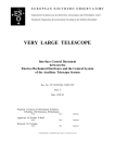
The azimuth axis can move in the range (-180,360) degrees. This means that for azimuth angles in the
range (-180,0)=(180,360) degreees there are two possible positions of the axis.
The terminology used here is:
- the DIRECTION in which azimuth is'looking' is called 'direction azimuth', DAZ, and is in the range
(0,360) degrees
- the absolute POSITION angle of the axis is called 'position azimuth' PAZ, and is in the range (-180,+360)
degrees.
So, for a given 'direction azimuth' in the range (180,360) degrees there are two possible 'position azimuth'.
These tests shall verify that the az axis control, including handling of the encoder, moves in the correct
way; when moving to a new position in the ambigous range, the 'position azimuth' that is closest should be
selected.
360
0
90
270
-180
180
Figure 1 Azimuth angles
6.4.2
Actions/Test cases
Use commands to aztrkServer.
It is assumed that the azimuth range is defined in the database to be (-180,360) deg
Test Id
Command/Action
AZ4-1 set azServer ONLINE
2 set aztrkServer ONLINE
3 OBJFIX 89,10
4 OBJFIX 89,350
5
OBJFIX 89,185
6
OBJFIX 89,179.999
7
OBJFIX 89,175
8
OBJFIX 89,185
9
OBJFIX 89,350
Expected Result/Status
az axis moves to 10 deg
axis moves clock-wise to
PAZ=-10, DAZ=350
axis moves clockwise to
PAZ=-175, DAZ=185
axis moves clockwise to
PAZ=-179.99
DAZ=180.01
counterclockwise to
PAZ=175, DAZ=175
counterclockwise to
PAZ=185 DAZ=185
counterclockwise to
PAZ=350, DAZ=350
Test date
Test result
Liège Test Plan
ESO
10
OBJFIX 89,359.9
11
OBJFIX 89,10
12
OBJFIX 89,90
13
STANDBY
counterclockwise to
PAZ=359.9,DAZ=359.9
clockwise to
PAZ=10, DAZ=10
clockwise to
PAZ=90,DAZ=90
Doc:
Issue:
Date:
Page:
VLT-VER-ESO-15151-2738
2.0
2002-03-05
32 of 74
ESO
6.5
Doc:
Issue:
Date:
Page:
Liège Test Plan
VLT-VER-ESO-15151-2738
2.0
2002-03-05
33 of 74
Azimuth tracking
6.5.1 Description
The tracking functionality is exactly the same as for the UTs, so there is no need to repeat all that functionality. Here are defined just a few cases to verify that the interface between tracking and axis control is OK.
Test start condition:
- the az axis is ONLINE
Use ccseiMsg to send commands and get status to aztrkServer.
6.5.2
Actions/Test cases
Test Id
AZ5-1
AZ5-2
AZ5-3
AZ5-4
AZ5-5
AZ5-6
AZ5-7
AZ5-8
AZ5-9
Command/Action
INIT
ONLINE
OBJFIX 40,50
OFFSAA 3600,3600
OFFSAD 10,20
OBJSTAR 101112,-880000
STATUS
OFFSAA 50,60
OFFSAD 3600,3600
Expected Result/Status
state becomes Loaded
state becomes ONLINE
motor moves to 50 deg
motor moves to 51 deg
rejected (not tracking)
Motor presets and then
starts tracking
Substate TRACKING
Rejected, while tracking
OK
Test date
Test result
Liège Test Plan
ESO
6.6
M10 control
6.6.1
Description
Doc:
Issue:
Date:
Page:
VLT-VER-ESO-15151-2738
2.0
2002-03-05
34 of 74
In addition to ccseiMsg the panel atm10gui is used to send commands and check status.
6.6.2
Actions/Test cases
Whern the test starts, no M10 commands have been sent since last reboot of the LCU.
Test Id
AZ6-1
Command/Action
Check controller tuning
(speed,acc, etc)
Save config
2
Check Init sequence
Save config
3
VERSION
4
5
6
7
8
9
10
11
SIMULAT
GETSIM
STOPSIM
GETSIM
STATE
STATUS
INIT
STATUS
12
13
14
15
16
17
18
ONLINE
GETTILT
SETTILT 1.2,3.4
GETTILT
CENTER
STOP
OFF
Expected Result/Status
OK reply with correct
version and date
OK
On
OK
Off
Loaded
Loaded, simulation off
OK
Loaded, substate IDLE,
initialised
ONLINE, Idle
Returns alpha and beta
OK
alpha=1.2, beta=3.4
Test date
01MAR
Test result
OK on beta axis. Alpha not yet
tuned. AMOS to provide
parameters.
Overall position accuracy is low.
Missing conversion function for
alpha axis.
OK
AMOS to provide encoder values
of the optical center position.
OK
Functionally OK but scaling not
correct yet. ESO to implement.
OK
Liège Test Plan
ESO
6.7
Coudé Focus Device functions
6.7.1
Description
Doc:
Issue:
Date:
Page:
VLT-VER-ESO-15151-2738
2.0
2002-03-05
35 of 74
In addition to ccseiMsg the panel atcfdgui is used to send commands and check status.
6.7.2
Actions/Test cases
Test Id
AZ7-1
2
Command/Action
Check controller tuning
(speed,acc, etc)
Save config
Align wheel positions.
Save config
3
4
5
6
7
8
9
10
11
VERSION
SIMULAT
GETSIM
STOPSIM
GETSIM
STATE
STATUS
INIT
STATUS
12
13
14
15
16
17
18
19
20
21
22
ONLINE
SETBEAM stop
GETBEAM
SETBEAM mirror
GETBEAM
SETBEAM split
GETBEAM
SETBEAM hole
GETBEAM
STOP
OFF
Expected Result/Status
Test date
18FEB
Test result
OK
Relative positions defined
according to drawing but not
calibrated wrt LHW/REF
OK
OK
On
Loaded
Loaded, Substate Idle,
Beam SPLIT
OK
OK
Light Stop
OK
Mirror
OK
Beam splitter
OK
Hole
The maximum speed of 2mm/s could only be achived (FISBA claims 5mm/s mec.). The position accuracy could be
reached down to 2 Enc = approx. 0.35micrometers. Is this sufficient? Relaxing this constraint could allow to increase the
max. speed.
Added new element “Pupil Field Viewer” as not known by SW team. Elements separated by 47mm nominal acc. To
drawing. Range between limits is 200mm.
Question for ESO: what is the position accuracy (not specified yet)? Especially for the Pupil field viewer.
Liège Test Plan
ESO
7.
Doc:
Issue:
Date:
Page:
VLT-VER-ESO-15151-2738
2.0
2002-03-05
36 of 74
LCU FUNCTIONS - AUX
Purpose:
Pre-requisite:
Systematically check through all LCU application functionality in a bottom-up
approach.
IO-signals OK
Duration:
Requires:
The activities have been assigned test IDs as follows:
•
AUX1: Siemens PLC functions (ecs,ros,srv,trl)
•
AUX2: Sauter PLC functions (acs)
7.1
Siemens PLC functions
7.1.1
Description
7.1.2
Actions/Test cases
Test Id
Command/Action
7.2
Sauter PLC functions
7.2.1
Description
Expected Result/Status
Test date
Test result
Expected Result/Status
Test date
Test result
Actions/test cases
Test Id
Command/Action
Liège Test Plan
ESO
8.
Doc:
Issue:
Date:
Page:
VLT-VER-ESO-15151-2738
2.0
2002-03-05
37 of 74
LCU FUNCTIONS - DCS
Purpose:
Systematic check of all LCU application functionality in a bottom-up approach.
Pre-requisite:
IO-signals OK
Duration:
Requires:
The activities have test IDs as follows:
• DCS1: Check utility I/O signals
•
DCS2: FSS device (STRAP)
•
DCS3: FAS device (TCCD)
•
DCS4: XY-table functions
•
DCS5: M6 functions
•
DCS6: NDF + AFD functions
•
DCS7: probe tracking
8.1
Check utility I/O signals
8.1.1
Description
This section is testing some special utility functions that are controlled via digital I/O signals. The
functions are tested using the panel atdcssrvgui.
Test Id
Command/Action
DCS1-1 INIT,ONLINE
DCS1-2
switch on TCCD
DCS1-3
switch off TCCD
DCS1-4
DCS1-5
DCS1-6
switch on M6 amplifier
switch off M6 amplifier
M6 in position
DCS1-7
DCS1-8
M6 overflow
STRAP Gate
DCS1-9
Reset STRAP
DCS1-10
check flow meter reading
Expected Result/Status
Status goes ONLINE
Test date
20FEB
ACE box of TCCD is
switched on
ACE box switched off
20FEB
M6 amplifier switched on
M6 amplifier switched off
Signal active when M6 on
target
Signal active on overflow
STRAP counting when
active
STRAP reset Led goes On
for a fraction of a second
Act on cooling pump to see
the flow meter reading.
Stop the pump, flow meter
shall read ZERO.
Test result
OK
ACE powered On
OK
20FEB
25FEB
NOK
Bound all ground lines on Y31
OK
21FEB
LCU function OK, but not tested
electrically on STRAP input
NOK: Reset line is always active
OK after reversed logic in I/F board
LCU output signal is active High,
STRAP input signal is active Low
Not mounted in cooling circuit yet.
21FEB
22FEB
Liège Test Plan
ESO
8.2
Doc:
Issue:
Date:
Page:
VLT-VER-ESO-15151-2738
2.0
2002-03-05
38 of 74
FSS device (STRAP)
8.2.1 Description
This section is testing the basic commands and the basic motions of the STRAP. Some performance tests
have been done prior to the integration tests, and these will not be re-done here. These performance tests
are listed in the table below, for completeness, and the results will be made available as part of the
integration tests report.
Use the panel atfssgui to send commands and to monitor STRAP.
It is assumed that the basic configuration and setting of SETUP parameters of STRAP has been done
before these tests start. For info how to do these things, see RD- 2
8.2.2
Actions/Test cases
The LCU latxdcs shall be re-booted just before start of the tests.
Test Id
DCS2-1
DCS2-2
DCS2-3
DCS2-4
Command/Action
Expected Result/Status
Generate STRAP interaction matrix
See RD- 2
Save the new interaction matrix
Check that STRAP is counting
put XY-table in center position
INIT
ONLINE
Current values of temp and
High Voltages becomes =
the SETUP values
SETTHR 0
Threshold=0
Switch on a Nasmyth beacon
Start Open loop
The APD counts starts
counting
Change beacon level until at least 1
APD count gets > 1000000
Check Closed Loop
Close loop
Open loop
Move XY-table such that the max
count is in another APD
Close loop
at least 1 of the APDs gets
a high count
STRAP outputs corrections
to M6 (M6 might go to end
pos!)
M6 corrections changed
direction
Perform the XY-table tests, incl.
centering XY-table on star, and
the TCCD tests before
proceeding with the following
STRAP tests
DCS2-5
Check Closed loop behaviour
Put XY-table in center-of-star pos.
Have sequential exposures running
on TCCD
See test 8.4.2
Close STRAP loop
Offset XY-table in X 165 µ (=0.5")
Offset XY-table in Y 165 µ (=0.5")
small centroids (<10-4)
small M6 corr. (<0.1")
M6 is corrected by 0.5"
Star moves 0.5" on TCCD
M6 is corrected 0.5" , 90
deg rotated to previous
Test date
Test result
01MAR
01MAR
OK
OK after the coolant had a
temperature below 10C (hardcoded
in the STRAP SW).
01MAR
OK (with cap on STRAP head)
Counts were (samples):
Cts: 200; 322; 312; 418; 264; 209
RMS: 13; 17.6; 17; 18.8; 16.2; 13.2
RMS = approx sqrt(Counts)
ESO
Liège Test Plan
Offset XY-table in X -165µ
Offset XY-table in Y -165µ
Set XY-table X velocity to 0.1"/s
DCS2-6
Open loop
Stop XY-table
STRAP INIT
Check STRAP linearity
D:o star motion on TCCD
M6 going back
M6 going back
M6 moving 0.1"/s
Centroids always small
See coming Test Report
Doc:
Issue:
Date:
Page:
VLT-VER-ESO-15151-2738
2.0
2002-03-05
39 of 74
Liège Test Plan
ESO
8.3
FAS device (TCCD)
8.3.1
Description
Doc:
Issue:
Date:
Page:
VLT-VER-ESO-15151-2738
2.0
2002-03-05
40 of 74
The TCCD head is mounted "before" the XY-table and STRAP but "after" M6. That is to say that M6
motions will move the star on the TCCD but XY-table/STRAP head motions will NOT.
The CCD stand-alone control panel is used to control the TCCD and images are displayed using the
tcscam/rtd.
8.3.2
Actions/test cases
The LCU is just booted before the tests start.
STRAP should be in LOADED or ONLINE/Open loop.
M6 amplifier is switched on.
Test Id
Command/Action
DCS3-1 Start the TCCD panel:
ccdStartFas
DCS3-2 Start tcscam/rtd:
rtdStartFas
DCS3-3 SHUTDOWN the CCD
DCS3-4 Startup TCCD
Expected Result/Status
The panel comes up
State goes to OFF
State goes to ONLINE
Test date
22FEB
22FEB
OK
22FEB
22FEB
27FEB
OK
NOK: discontinuity in optical
fibers
OK with direct ESO fibers
The optical mergers in the ROS
were found in opposite direction.
Tested all fibers from LCU to ACE
Found discontinuity in socked #1
Used fiber #3 instead
OK
OK
27FEB
OK
27FEB
No “star” available yet, but dark
image correct, no visible patterns
Dark level correct.
27FEB
DCS3-5
Start Sequential exposures,
with exp. time 0.1 sec
in rtd panel: attach the
camera
switch on the "star" and
adjust voltage
Exposure active,
exposure counting starts
green transmission
indicator starts blinking
the "star" is approx. in
the center of the image
DCS3-8
change exposure time
display brightness
changes
DCS3-9
SHUTDOWN
DCS3-6
DCS3-7
Test result
OK
27FEB
The color assignment for the fiber bound LCU-GIS is: #1 Black; #2 Red; #3 Orange; #4 Yellow; #5 Green; #6 Blue.
AMOS: it is essential that the continuity tests are made from the LCU to the ACE. The continuity test performed from
the GIS socket down to the mergers is in no way sufficient.
AMOS: The GIS socket #1 shall be checked. The GIS fiber sockets must be labelled.
Liège Test Plan
ESO
8.4
Doc:
Issue:
Date:
Page:
VLT-VER-ESO-15151-2738
2.0
2002-03-05
41 of 74
XY-table functions
8.4.1 Description
This section is testing the basic commands and the basic motions of the XY-table. Some XY-table
performance tests have been done prior to the integration tests, and these will not be re-done here. These
performance tests are listed in the table below, for completeness, and the results will be made available as
part of the integration tests report.
Tracking is tested in section 8.7 below.
Use the panel atxytgui to send commands and get status from the XY-table, or use ccseiMsg for commands not implemented in the panel. Commands are sent to atxytServer.
At start of the test the LCU is newly re-booted.
8.4.2
Actions/Test cases
Test Id
Command/Action
DCS4-1 Check accuracy of offset steps
-2
-3
-4
-5
-6
-7
-8
-9
-10
-11
-12
-13
-14
-15
-16
-17
Expected Result/Status
In spec
See the coming Test Report!
Check of absolute position
In spec
reproducibility
See the coming Test Report!
Check position hysteresis
none
See the coming Test Report!
Check the position accuracy during
In spec
tracking
See the coming Test Report!
VERSION
STATE
Loaded
STATUS
State Loaded, substate Idle
INIT
both axes initialise, State
stays Loaded, substate gets
INITIALISED
position is x=y=0
ONLINE
State becomes ONLINE
Set x=5.001,y=6.002, push
XY table moves to x/
PRESET
y=(5.001,6.002), panel
command SETXYP
updated
Set x=11,y=5, push
command rejected, log
PRESET
message
Set x=9.8,y=-9.8, push
XY table moves to (9.8,PRESET
9.8)
Click “Pos” under TRACKING, set XY table moves to
x=-7 y=8
(-7,8) , panel updated
push TRACKING
command SETXYTP
Click “Vel” under TRACKING, set XY table moves with 0.1
Vx=0.1Vy=-0.1 mm/s
mm/s.
push TRACKING
command SETXYTV
Stop after 20 sec, by setting
velocities=0
Send STOP
Set offsets = 5.0,-5.0
push OFFSET
command SETXYR
Align XY-table on the star
Move XY-table to make STRAP
centroids smaller, and APD
readings more balanced
Close STRAP loop
XY table stops at approx.
(0.0,0.0)
XY table makes offset step
to (5.0,-5.0)
Test date
20FEB
Test result
OK
(see comments below)
ESO
-18
-19
Doc:
Issue:
Date:
Page:
Liège Test Plan
If M6 goes into limit, Open loop
and go back to step 1
If M6 is not in limit, fine-adjust the
XY-table position so that STRAP
output to M6 is small (|tilt|<0.1")
Take note of this XY-pos, and use
it as XY-table offset!
STANDBY
OFF
State
State
STANDBY
Loaded
20FEB
20FEB
VLT-VER-ESO-15151-2738
2.0
2002-03-05
42 of 74
OK
OK
The bouncing already observed in Garching was still present on the Lower Limits of both axes. Not tested on the Upper
limits.
The measured range is 46.58mm in X and 46.45mm in Y instead of the 50mm announced by FISBA.
Decreasing the speed down to 0.5mm/s instead of the 1.5mm/s used so far could reduce the bouncing. An additional
delay of 5s has been introduced prior to move to center.
The Initialization Sequence for both axes is now:
• Find LHW @ 0.5mm/s
• Delay 5s
• Calibrate ABS –25mm
• Move ABS 0mm @ 1.5mm/s
Special Positions:
• UHW=LHW+45.5mm
Software Limits set as:
• LSW=LHW+0.1mm
• USW=UHW-0.1mm
ESO
Liège Test Plan
8.5
NDF + AFD Functions
8.5.1
Description
Doc:
Issue:
Date:
Page:
VLT-VER-ESO-15151-2738
2.0
2002-03-05
43 of 74
These two motorized axes are controlling the Neutral Density Filter wheel (for STRAP flux limitation) and
the Aperture Field Diaphragm (inside the STRAP head).
8.5.2
Actions/Test cases
Test Id
Command/Action
DCS5-1 NDF axis
DCS5-2 AFD axis
Expected Result/Status
Test date
19FEB
Test result
NOK (see comment below)
N/A (cabling not done by AMOS
yet)
The Reference Switch is seen always active by the MACCON board. After replacement of the VME4SA back-plane, is
has been OK for some time then failed again. The switch is correctly working and the problem seems to be lying in the
MACCON board (TTL levels). ESO TEC HW team to solve.
ESO
8.6
M6
8.6.1
Description
Liège Test Plan
Doc:
Issue:
Date:
Page:
VLT-VER-ESO-15151-2738
2.0
2002-03-05
44 of 74
The M6 is controlled by STRAP; there is no way to move M6 except doing it via STRAP. In fact, testing
STRAP also requires M6, so the two are very much integrated.
The interaction matrix, that relates a STRAP error vector with the corresponding M6 correction, is
measured and calculated using a dedicated STRAP functionality; see RD- 2.
The coefficients for the M6 controller in STRAP have been determined before these tests. This operation is
described in the coming Integration Test Report.
8.6.2
Actions/Test cases
Test Id
Command/Action
DCS6-1
Expected Result/Status
Test date
Test result
Liège Test Plan
ESO
8.7
Doc:
Issue:
Date:
Page:
VLT-VER-ESO-15151-2738
2.0
2002-03-05
45 of 74
Probe tracking
8.7.1 Description
The objective of this test section is to demonstrate that the “guide probe” of the ATs can be positioned and
can track according to spec. The LCU tracking module itself is completely inherited from VLT, and needs
not be tested in this context; it is the implementation of the XY-table as a guide probe, i.e. the autoguiding
related positioning and tracking that is to be tested. For this reason, it is mainly the commands to
probeServer that are to be tested, whereas prbtrkServer is “only” used to set up the relevant test cases.
The Use Cases Tests, see chapter 10, of course includes the complete chain involved in presetting, tracking
and offsetting of the XY-table, i.e. also the tracking parts!
Use the panel atguiGA to send commands and monitor status of the probe, and use ccseiMsg for the basic
commands (not available on the panel).
Conditions at start of tests:
- the XY-table is ONLINE
- probetrkServer is ONLINE
- ccdfas is ONLINE
8.7.2
Actions/Test cases
Commands are sent to probeServer except where other receiver explicitly mentioned.
Test Id
Command/Action
DCS7-1 STATE
-2 STATUS
-3
-4
-5
-6
DIFTOFF
DIFTON
INIT, ONLINE
Set xy-table in pos (3.0,4.0)
PRCNT
Change center position in
database!
UPDATE
PRCNT
-7
PRPARK
-8
Start tracking.
send to probetrkServer:
OBJSTAR
181920.1,-883344.2
PRABS AD,181920.1,
-883334.2,,,,,,,,540
-9
-10
PRCHK 0,0,0,190000,883344,,,567
OFFSAD 1800,-1800
PRSOFF 30,-30
Expected Result/Status
Loaded
Loaded
No GS selected
Diff trk on
RecalcRef No
DiffTrk off
Diff trk on
state ---> ONLINE
Probe moves to center
position
:probe:data:atp:xyt:config.xOffset
Probe moves to new
center pos
probe moves to Park
position
probetrkServer to substate TRACKING
probe moves approx. 3
mm, gs wavelength 540
nm
Rejected. Position out of
range
probe moves to position
182120.1,-880344.2
Test date
Test result
Liège Test Plan
ESO
-11
PROBJ
STANDBY
probe moves to position
181920.1,-88334
This is the local effect of
this command at
probeServer level.
Other actions, on higher
level, are not tested
here!4.2
Doc:
Issue:
Date:
Page:
VLT-VER-ESO-15151-2738
2.0
2002-03-05
46 of 74
Liège Test Plan
ESO
9.
Doc:
Issue:
Date:
Page:
VLT-VER-ESO-15151-2738
2.0
2002-03-05
47 of 74
MODULE TESTS OF WORKSTATION MODULES
Purpose:
Run the module tests for all workstation modules.
Pre-requisite:
Duration:
Requires:
The activities have been assigned test IDs as follows:
•
9.1
MT01:
Description
The modules tests are run on the target machine, with the ATCS system fully installed and the
environment running. In this case, the sequence of testing is not important. ( TRUE ????)
9.2
Actions/Test cases
Test Id
MT01-1
-2
-3
-4
-5
-6
-7
-8
-9
-10
-11
-12
-13
-14
-15
-16
-17
-18
-19
-20
Module
agws
atagws
atact
atcsmon
atecsws
astgui
atosf
msw
atmsw
prs
atprs
chopws
fsws
pom
pomgui
tcs
tcscam
tcsmon
tif
trkws
Version
Result
Test result
ESO
10.
Liège Test Plan
Doc:
Issue:
Date:
Page:
VLT-VER-ESO-15151-2738
2.0
2002-03-05
48 of 74
USE CASES
Purpose:
Pre-requisite:
WS module tests passed, LCU function tests passed
Duration:
Requires:
Use Cases are defined in AD- 1, and the tests of Use Cases on AT #1 in Liège are documented in the
internal document "ATCS- Tests of Use Cases, AT #1", which is supplied as a separate attachment to this
document.
Liège Test Plan
ESO
11.
Doc:
Issue:
Date:
Page:
VLT-VER-ESO-15151-2738
2.0
2002-03-05
49 of 74
INTEGRATION TEST SCENARIOS
Purpose:
- to test more cases, in particular more error cases, than defined in the Use Cases
- to test parallel activities that are usually not defined in Use cases
Pre-requisite:
UC tests passed
Duration:
Requires:
The activities have test IDs as follows:
• INT1: startup and shutdown
• INT2: Presetting
• INT3: Tracking
• INT4: Guiding, Field Stabilisation
• INT5: Chopping
11.1
Startup and shutdown
11.1.1 Actions/Test cases
Test Id
Command/Action
Expected Result/Status
start atguiStatus
Check commands INIT,
ONLINE, STANDBY for
all modules
-3 Check that actual STATE is
OK for all modules
-4 Check that IGNORE button
works correctly for all
modules
INT1-1
-2
Test date
Test result
Liège Test Plan
ESO
11.2
Doc:
Issue:
Date:
Page:
VLT-VER-ESO-15151-2738
2.0
2002-03-05
50 of 74
Presetting
11.2.1 Presets and offsets
Use ccseiMsg to send commands to prsControl. and trkwsControl .
Test Id
Command/Action
INT2-1 Set TCS ONLINE
2 PRSALAZ 60,90
3 PRSNAME zenith
4 PRSALAZ 50,350
5 PRSNAME PARK
6 PRSALAZ 10,350
7 PRSALAZ 50,350
8 OFFSAD 10,10
9
10
11
12
13
14
15
16
17
18
OFFSAA 30,0
OFFSAA 0,60
OFFSAA –1,-2
PRSCOOR
<HA~0>, -450000
GETREM
PRSCOOR
<HA~0>, -450000
PRSCOOR
<HA~0>, -850000
PRSCOOR
<HA~-1h>, -600000
Expected Result/Status
Rejected (alt low)
Rejected (not allowed in
this mode)
Offset step in alt only
Offset step in az only
OK
>= 6 hours
Telescope starts moving
When moving do:
PRSCOOR
<HA~+1h>, -600000
Starts moving to new
target
When moving do:
PRSCOOR
<HA~-1h>, -600000
OFFSAA 10,20
OFFSAD 60,0
Starts moving to new
target
Rejected (not tracking)
The change in RA actual
position
=60/(15*cos(60))=8 sec
Test result
Liège Test Plan
ESO
11.3
Doc:
Issue:
Date:
Page:
VLT-VER-ESO-15151-2738
2.0
2002-03-05
51 of 74
Tracking
11.3.1 Tracking into limits/Calculation of remaining tracking time
This is a set of tests where the telescope is preset to a position close to a limit and then left tracking until it
reaches the limit. At that point, tracking shall be stopped by the alt axis. The workstation module (trkws)
stops all tracking axes by sending a STOP command to them. All tracking LCUs and also trkws stay
ONLINE, IDLE.
Before the telescope reaches the limit, the handling of ‘remaining tracking time’ shall be checked and
verified:
- cyclical calculation and update in ws database
- the ws command GETREM (without parameters) to get actual value
- alarm when the actual value is < ‘remaining tracking time limit’
Test Id
Command/Action
INT3-1 SETRLIM 120
2
Expected Result/Status
Test date
‘rem. track time limit’ set to
2 minutes
Limit is reached when
HA=-000213
8 minutes
5
‘STAR object’
<HA~-0.25>, -243700
when HA~-10 min.:
GETREM (no params)
when HA~-5 min.:
GETREM (no params)
When HA ~-4 min.
6
when HA~2min13sec
7
‘STAR object’
Limit is reached when
<HA~+5h20min>, -400000 HA~053600
when HA~:5h25
11 minutes
GETREM (no params)
3
4
8
9
10
when HA~5h30m
GETREM (no params)
when HA ~5h34m
11
when HA~5h36m
12
preset to named object
ZENITH
3 minutes
ALARM
'Rem. track time low'
Tracking stopped
Check that the behaviour is
as described above
6 minutes
ALARM
'Rem. track time low'
Tracking stopped
Check that the behaviour is
as described above.
Test result
Liège Test Plan
ESO
Doc:
Issue:
Date:
Page:
VLT-VER-ESO-15151-2738
2.0
2002-03-05
52 of 74
11.3.2 Tracking error cases
These tests shall verify that the complete tracking system is stopped correctly in the following error cases:
• LCU failed:
− it unexpectedly left state ONLINE
− unexpected power off
• an interlock signal was asserted
The correct behaviour for these errors is:
• LCU failed
The ws process trkws is event triggered. When triggered it sends command STOP to all other tracking
LCUs (i.e. azimuth and xy-table), which then go to state ONLINE/IDLE.
• interlock signal ASSERTED
− a log message is generated, giving the name of the interlock signal
− the position loop is opened
− the velocity reference is set to 0
− the velocity loop is opened
− the power amplifiers are disabled
− set state to STANDBY
For each of the simulated error test cases, the correct and complete set of actions as described above shall
be checked. In the case of Interlocks, it shall also be checked that the telescope remains switched off and
standing still when the interlock signal is NEGATED.
Sending command OFF to aztrkServer or alttrkServer simulates the error 'LCU failed'. Use the switches to
simulate interlocks. Since all interlock signals cause the same set of actions, it is enough to test on the
signal INTERLOCKI, which is asserted hardware-wise whenever ANY interlock signal is asserted (this
latter fact was tested in the hardware sections above!).
Before the tests start, alt and az LCUs shall be rebooted. Use panels atguiStatus and atguiTCS to send
commands.
Test Id
Command/Action
INT3-13 Set tracking LCUs and WS
ONLINE
14 Preset to object
HA~3h, dec=-450000
15 OFF to altServer
Expected Result/Status
All ONLINE
Telescope presets and
starts tracking
alt LCU goes
ONLINE,IDLE
Check actions; see above
16
17
18
19
set all ONLINE again
Preset to object
HA~3h, dec=-450000
set INTERLOCKI =TRUE
set INTERLOCKI=FALSE
Telescope presets and
starts tracking
Check actions; see above
no reaction on telescope
or any module
Test result
Liège Test Plan
ESO
11.4
Doc:
Issue:
Date:
Page:
VLT-VER-ESO-15151-2738
2.0
2002-03-05
53 of 74
Guiding, Field Stabilization
Test various error cases:
loosing guide star
tracking stopped
TCCD/STRAP not ONLINE
…..
11.4.1 Actions/Test cases
Test Id
Command/Action
Expected Result/Status
Test date
Test result
Liège Test Plan
ESO
11.5
Doc:
Issue:
Date:
Page:
VLT-VER-ESO-15151-2738
2.0
2002-03-05
54 of 74
Chopping
- various choppping params
- chopping +FS
- chopping + AG
- errors while chopping
11.5.1 Actions/Test cases
Test Id
Command/Action
Expected Result/Status
Test date
Test result
ESO
Liège Test Plan
Doc:
Issue:
Date:
Page:
VLT-VER-ESO-15151-2738
2.0
2002-03-05
55 of 74
12.
APPENDIX 1: SIGNAL CONFIGURATION FILES
12.1
Altitude analogue signals
#******************************************************************************
# E.S.O. - VLT project
#
# "@(#) $Id: ataltazAltAnalog.config,v 1.30 2002/01/22 13:41:24 vltsccm Exp $"
#
# who
when
what
# -------- -------- ---------------------------------------------# kwirenst 2001-04-03 Based on Signal List Draft 2
# atcsmgr 2000-11-23 created
#
#************************************************************************
#
NAME
#
#
SYNOPSIS
#
#
DESCRIPTION
#
#
FILES
#
#
ENVIRONMENT
#
#
RETURN VALUES
#
#
CAUTIONS
#
#
EXAMPLES
#
#
SEE ALSO
#
#
BUGS
#
#-----------------------------------------------------------------------# name
device
number
conv range
# ------------------------------------------------------###TELTEMP1I
/aio0
0
1.0
-10.0 +10.0 1
###TELTEMP2I
/aio0
1
1.0
-10.0 +10.0 1
###TELTEMP3I
/aio0
2
1.0
-10.0 +10.0 1
###TELTEMP4I
/aio0
3
1.0
-10.0 +10.0 1
###TELTEMP5I
/aio0
4
1.0
-10.0 +10.0 1
###TELTEMP6I
/aio0
5
1.0
-10.0 +10.0 1
###TELTEMP7I
/aio0
6
1.0
-10.0 +10.0 1
###TELTEMP8I
/aio0
7
1.0
-10.0 +10.0 1
###TELTEMP9I
/aio0
8
1.0
-10.0 +10.0 1
###TACHOFI
/aio0
9
1.0
-10.0 +10.0 1
###VCCVLO
/aio0
10
1.0
-10.0 +10.0 1
###TREFINI
/aio0
11
1.0
-10.0 +10.0 1
###PHASEMONITORI
/aio0
12
1.0
-10.0 +10.0 1
###A00CWI
/aio0
13
1.0
-10.0 +10.0 1
###EXTREF
/aio0
14
1.0
-10.0 +10.0 1
###TP7I
/aio0
15
1.0
-10.0 +10.0 1
###TREFOUTO
/aio0
0
1.0
-10.0 +10.0 1
###AUXOUTO
/aio0
1
1.0
-10.0 +10.0 1
# ___oOo___
0.0
0.0
0.0
0.0
0.0
0.0
0.0
0.0
0.0
0.0
0.0
0.0
0.0
0.0
0.0
0.0
0.0
0.0
ESO
Liège Test Plan
Doc:
Issue:
Date:
Page:
VLT-VER-ESO-15151-2738
2.0
2002-03-05
56 of 74
ESO
12.2
Liège Test Plan
Doc:
Issue:
Date:
Page:
VLT-VER-ESO-15151-2738
2.0
2002-03-05
57 of 74
Altitude digital signals
#******************************************************************************
# E.S.O. - VLT project
#
# "@(#) $Id: ataltazAltDigital.config,v 1.30 2002/01/22 13:41:25 vltsccm Exp $"
#
# who
when
what
# -------- -------- ---------------------------------------------# kwirenst 2001-09-10 OPDOORI deleted, BRAKEnDISI set active high.
# kwirenst 2001-04-03 Based on Signal List Draft 2
# atcsmgr 2000-11-23 created
#
#************************************************************************
#
NAME
#
ataltazAltDigital.config - ALT digital signals configuration file
#
#
SYNOPSIS
#
#
DESCRIPTION
#
#
FILES
#
#
ENVIRONMENT
#
#
RETURN VALUES
#
#
CAUTIONS
#
NEVER remove the "info" field or leave one of the fields empty.
#
The software won't tell you, it will let you search the error
#
for hours!
#
#
EXAMPLES
#
#
SEE ALSO
#
#
BUGS
#
#-----------------------------------------------------------------------# name
device
bit
width sim
info
# --------------------------------------------------### was used on lat0alt
### DRENABO*
/acro0 32
1
0
DriveEnable
##
##
ILENDSTOPSAI
/acro0 14
1
0
?
ILENDSTOPSBI
/acro0 15
1
0
?
TIM1_HWG4O
/acro0 16
1
0
?
TIM1_HWG5O
/acro0 17
1
0
?
TIM1_TOUT0I
/acro0 18
1
0
?
TIM1_TOUT1I
/acro0 19
1
0
?
P24VOKI*
/acro0 20
1
0
?
NEGVMOKI*
/acro0 21
1
0
?
POSVMOKI*
/acro0 22
1
0
?
VXOKI*
/acro0 23
1
0
?
WDTMTI
/acro0 27
1
0
?
SPAREOUTO
/acro0 28
1
0
?
ESO
SPAREINI
/acro0
VCCVLO*
/acro0
### used form AT1 on
ILMOTIONSTOPI
/acro0
BRAKE2DISI
/acro0
BRAKE1DISI
/acro0
ILOVERRIDEI*
/acro0
MOTPOWEREDI
/acro0
ILENABLEO_DIOO /acro0
P400VOKI
/acro0
ILOVERSPEEDI
/acro0
ILFAULTI
/acro0
ENCODEROKO
/acro0
TACHOHIGHSENSI /acro0
ILMANUALI
/acro0
VICINITYNEGI*
/acro0
VICINITYPOSI*
/acro0
HOME1I
/acro0
ILRELOCATIONI
/acro0
ILLOCKPIN1I
/acro0
ILPOSLIMI
/acro0
ILNEGLIMI
/acro0
TACHOHIGHSENSO /acro0
TACHOOKI
/acro0
RESETI*
/acro0
ILLOCKPIN2I
/acro0
INTERLOCKI
/acro0
SPAREOPTO
/acro0
SPEEDMODEI
/acro0
### used form AT1 on
DRIVEENABLEO*
/acro0
ILRESETO*
/acro0
ILBRAKEMANI*
/acro0
P24VONO
/acro0
# ___oOo___
Doc:
Issue:
Date:
Page:
Liège Test Plan
29
30
1
1
0
0
?
?
32
33
34
35
37
38
39
40
41
42
43
44
45
46
47
48
49
50
51
52
53
55
56
57
58
59
1
1
1
1
1
1
1
1
1
1
1
1
1
1
1
1
1
1
1
1
1
1
1
1
1
1
0
0
0
0
0
0
0
0
0
0
0
0
0
0
0
0
0
0
0
0
0
0
0
0
0
0
?
?
?
?
?
?
?
?
?
?
?
?
?
?
?
?
?
?
?
?
?
?
?
?
?
?
60
61
62
63
1
1
1
1
0
0
0
0
?
?
?
?
VLT-VER-ESO-15151-2738
2.0
2002-03-05
58 of 74
ESO
12.3
Liège Test Plan
Doc:
Issue:
Date:
Page:
VLT-VER-ESO-15151-2738
2.0
2002-03-05
59 of 74
Azimuth analogue signals
#******************************************************************************
# E.S.O. - VLT project
#
# "@(#) $Id: ataltazAzAnalog.config,v 1.30 2002/01/22 13:41:25 vltsccm Exp $"
#
# who
when
what
# -------- -------- ---------------------------------------------# kwirenst 2001-04-03 Based on Signal List Draft 2
# atcsmgr 2000-11-23 created
#
#************************************************************************
#
NAME
#
#
SYNOPSIS
#
#
DESCRIPTION
#
#
FILES
#
#
ENVIRONMENT
#
#
RETURN VALUES
#
#
CAUTIONS
#
#
EXAMPLES
#
#
SEE ALSO
#
#
BUGS
#
#-----------------------------------------------------------------------# name
device
number
conv range
# ------------------------------------------------------###TACHOFI
/aio0
9
1.0
-10.0 +10.0 1
###VCCVLO
/aio0
10
1.0
-10.0 +10.0 1
###TREFINI
/aio0
11
1.0
-10.0 +10.0 1
###PHASEMONITORI
/aio0
12
1.0
-10.0 +10.0 1
###A00CWI
/aio0
13
1.0
-10.0 +10.0 1
###EXTREF
/aio0
14
1.0
-10.0 +10.0 1
###TP7I
/aio0
15
1.0
-10.0 +10.0 1
###TREFOUTO
/aio0
0
1.0
-10.0 +10.0 1
###AUXOUTO
/aio0
1
1.0
-10.0 +10.0 1
# ___oOo___
0.0
0.0
0.0
0.0
0.0
0.0
0.0
0.0
0.0
ESO
12.4
Liège Test Plan
Doc:
Issue:
Date:
Page:
VLT-VER-ESO-15151-2738
2.0
2002-03-05
60 of 74
Azimuth digital signals
#******************************************************************************
# E.S.O. - VLT project
#
# "@(#) $Id: ataltazAzDigital.config,v 1.30 2002/01/22 13:41:23 vltsccm Exp $"
#
# who
when
what
# -------- -------- ---------------------------------------------# pduhoux 2001-10-26 STATIONIDI simVal=114=0x72 = Station 'G2'
# kwirenst 2001-09-10 BRAKEnDISI set active high
# kwirenst 2001-04-23 Added missing signal DIRSWITCH2I
# atcsmgr 2001-04-09 shorten name of DIRECTIONSWITCH1I
# kwirenst 2001-04-03 Based on Signal List Draft 2
# atcsmgr 2000-11-23 created
#
#************************************************************************
#
NAME
#
ataltazAzDigital.config - AZ digital signals configuration file
#
#
SYNOPSIS
#
#
DESCRIPTION
#
#
FILES
#
#
ENVIRONMENT
#
#
RETURN VALUES
#
#
CAUTIONS
#
NEVER remove the "info" field or leave one of the fields empty.
#
The software won't tell you, it will let you search the error
#
for hours!
#
#
EXAMPLES
#
#
SEE ALSO
#
#
BUGS
#
#-----------------------------------------------------------------------# name
device
bit
width sim
info
# --------------------------------------------------STATIONIDI*
/acro0 0
8
114
?
ILCWFAULTI
/acro0 11
1
0
?
ILCWNEGLIMI
/acro0 12
1
0
?
ILCWPOSLIMI
/acro0 13
1
0
?
ILGISDOORI
/acro0 14
1
0
?
ILEWAI
/acro0 15
1
0
?
TIM1_HWG4O
/acro0 16
1
0
?
TIM1_HWG5O
/acro0 17
1
0
?
TIM1_TOUT0I
/acro0 18
1
0
?
TIM1_TOUT1I
/acro0 19
1
0
?
P24VOKI*
/acro0 20
1
0
?
NEGVMOKI*
/acro0 21
1
0
?
POSVMOKI*
/acro0 22
1
0
?
ESO
VXOKI*
WDTMTI
SPAREOUTO
SPAREINI
VCCVLO*
ILMOTIONSTOPI
BRAKE2DISI
BRAKE1DISI
ILOVERRIDEI*
MOTPOWEREDI
ILENABLEO_DIOO
P400VOKI
ILOVERSPEEDI
ILFAULTI
ENCODEROKO
TACHOHIGHSENSI
ILMANUALI
VICINITYNEGI*
VICINITYPOSI*
DIRSWITCH1I
ILRELOCATIONI
ILPOSLIMI
ILNEGLIMI
TACHOHIGHSENSO
TACHOOKI
DIRSWITCH2I
RESETI*
ILSPARE1I
INTERLOCKI
SPEEDMODEI
DRIVEENABLEO*
ILRESETO*
ILBRAKEMANI*
P24VONO
Doc:
Issue:
Date:
Page:
Liège Test Plan
/acro0
/acro0
/acro0
/acro0
/acro0
/acro0
/acro0
/acro0
/acro0
/acro0
/acro0
/acro0
/acro0
/acro0
/acro0
/acro0
/acro0
/acro0
/acro0
/acro0
/acro0
/acro0
/acro0
/acro0
/acro0
/acro0
/acro0
/acro0
/acro0
/acro0
/acro0
/acro0
/acro0
/acro0
23
27
28
29
30
32
33
34
35
37
38
39
40
41
42
43
44
45
46
47
48
50
51
52
53
54
55
56
57
59
60
61
62
63
# ___oOo___
12.4.1 Detector LCU analogue signals
1
1
1
1
1
1
1
1
1
1
1
1
1
1
1
1
1
1
1
1
1
1
1
1
1
1
1
1
1
1
1
1
1
1
0
0
0
0
0
0
0
0
0
0
0
0
0
0
0
0
0
0
0
0
0
0
0
0
0
0
0
0
0
0
0
0
0
0
?
?
?
?
?
?
?
?
?
?
?
?
?
?
?
?
?
?
?
?
?
?
?
?
?
?
?
?
?
?
?
?
?
?
VLT-VER-ESO-15151-2738
2.0
2002-03-05
61 of 74
ESO
Liège Test Plan
12.4.2 Detector LCU digital signals
Doc:
Issue:
Date:
Page:
VLT-VER-ESO-15151-2738
2.0
2002-03-05
62 of 74
ESO
13.
Liège Test Plan
Doc:
Issue:
Date:
Page:
VLT-VER-ESO-15151-2738
2.0
2002-03-05
63 of 74
APPENDIX 2: PANELS
Should we include copies of some/ALL/none of the referenced panels????????
Liège Test Plan
ESO
14.
APPENDIX 3: HW CONNECTIONS
14.1
Altitude VME connections
Doc:
Issue:
Date:
Page:
VLT-VER-ESO-15151-2738
2.0
2002-03-05
64 of 74
See RD- 8 and annex01 for detail of connections listed herebelow
14.1.1 Connection/Test cases
Test Id
connection
230V VME
230V Fans
Protective Earth
TIME synchro
Control LAN
Temperature
Nasmyth wheel
Altitude Encoder
Field & PHASE amplifier
24V supply PHASE
amplifier
Amplifier analogue
PHASE serial link
M2 controller
Field supplies
Thermal controller
CPU console port
Expected Result/Status
RS485 during tests to
Sensor and Altitude via
cable wrap test or fibre
C17ESO
Optic fibre C16ESO
J6
Z3
X1
Z1
Z1 31, 24V
Z1 32 GND
J4
W13
Z11
JMACH1,
JMACH2,
JS1,
J8
J7,
J8,
Y1
W12
W10,
W11,
Z11
Test date
Test result
Liège Test Plan
ESO
14.2
Doc:
Issue:
Date:
Page:
VLT-VER-ESO-15151-2738
2.0
2002-03-05
65 of 74
Signal cabinet connections
14.2.1 Connection/Test cases
Test Id
14.3
connection
230V UPS to strip supply
230V NUPS to Fans strip
supply
Protective Earth
230V Thermal exchanger
NUPS
Expected Result/Status
Test date
Test result
Test date
Test result
Test date
Test result
Hub/Lan connections
See annex01of RD- 8 and for detail of connections listed herebelow
14.3.1 Connection/Test cases
Test Id
14.4
connection
Fiber 1 to 12 from AT
Station plug
Fibber 1 to 8 from cable
wrapp
Fibber 1 to 8 from cable
wrapp
230V UPS
Expected Result/Status
C1ESO/X206/OP1
C3 ESO/OP2/X200
C4 ESO/OP2/X200
Cable wrap connections
14.4.1 Connection/Test cases
Test Id
connection
Expected Result/Status
Motion stop and Relocation Z21 / Z5
interlock
Motion stop and Relocation Z11 / Z1
interlock
Altitude CPU0&CPU1
Z11/ W10, & W11
console ports
Altitude CPU0&CPU1
Z21/ W10’, & W11’
console ports at service
panel
Other connetions
Liège Test Plan
ESO
14.5
Doc:
Issue:
Date:
Page:
VLT-VER-ESO-15151-2738
2.0
2002-03-05
66 of 74
Service panel connections
14.5.1 Connection/Test cases
Test Id
14.6
connection
Altitude CPU0 console
Altitude CPU1 console
Expected Result/Status
W10’
W11’
Test date
Test result
Test date
Test result
Azimuth VME connections
See annex01 of RD- 8 for detail of connections listed below
14.6.1 Connection/Test cases
Test Id
connection
TIME synchro
Control LAN
Coudé Beam
TADC
Azimuth Encoder Head 1
Azimuth Encoder Head 2
Field & PHASE amplifier
24V supply PHASE
amplifier
Amplifier analogue
PHASE serial link
Field supplies
M10 controller
Azimuth CPU0 console
Altitude CPU1 console
Expected Result/Status
RS485 during tests to
Sensor and Altitude via
cable wrap
Optic fibre Hub 2T-Rx
Z10
Y20
X1
X3
X1
X3
Z5
Z5 31, 24V
Z5 32 GND
J4
V13
Z31
J7,
J8,
Y2
V14
Z31
W20
W23
Liège Test Plan
ESO
14.7
Doc:
Issue:
Date:
Page:
VLT-VER-ESO-15151-2738
2.0
2002-03-05
67 of 74
Sensor VME connections
See annex01 of RD- 8 for detail of connections listed herebelow
14.7.1 Connection/Test cases
Test Id
connection
TIME synchro
Control LAN
FSS Field diaphragm
FSS Filter wheel
FSS Translation stage X
FSS Translation stage Y
Field & PHASE amplifier
Amplifier analogue
PHASE serial link
TCCD Field supplies
TCCD fibber
STRAP/APD
Sensor CPU0 console
M6 Signal cabinet
Cooling flow sensor
Expected Result/Status
RS485 for test
Optic fibre Hub 4T-Rx
Y34
Z12
Z16
Z17
Z5
J4
V13
Z31
Lemo4a
Lemo4b
Y31
Y301 -308
Y32CL
Y32SG
Y32HV
V30
Y33
Y35
Test date
Test result
Liège Test Plan
ESO
14.8
Doc:
Issue:
Date:
Page:
VLT-VER-ESO-15151-2738
2.0
2002-03-05
68 of 74
M6 cabinet connections
See annex01 of RD- 8 for detail of connections listed below
14.8.1 Connection/Test cases
Test Id
connection
230V UPS
Protective earth
Cooling supply
M6 control Signal
Control Optic fibre
14.9
Expected Result/Status
X71
X71
inlet
outlet
X72
Y333
X204 ST 20
Test date
Test result
Test date
Test result
Auxiliary VME connections
See annex01 of RD- 8 for detail of connections listed below
14.9.1 Connection/Test cases
Test Id
connection
Control LAN
Air conditioning Sauter
Transporter Siemens PLC
Sensor CPU0 console
Expected Result/Status
Optic fibre Hub 5T-Rx
W41
Z31
W42
Z31
V30
Liège Test Plan
ESO
Doc:
Issue:
Date:
Page:
VLT-VER-ESO-15151-2738
2.0
2002-03-05
69 of 74
14.10 TCCD connections
See RD- 7for detailed connections scheme
14.10.1 ACE box Connection/Test cases
Test Id
Connection
Fiber links 1 to 6
Control supply
Peltier supply
Cooling pipe
Expected Result/Status
Test date
Test result
Expected Result/Status
Cable 1 to P11
Cable 2 to P12
Cable 3 to P13
Inlet
outlet
Test date
Test result
Expected Result/Status
Test date
Test result
Fiber optic 1 to 6 (SMA)
P21
P22
Inlet
outlet
14.10.2 TCCD Head Connection/Test cases
Test Id
Connection
J01
J02
J03
Cooling pipe
14.11 APD head connections
See RD- 6 for detailed connections scheme
14.11.1 Connection/Test cases
Test Id
Connection
Signal
High voltage
Control
Field diaphragm
Fisher 16 poles yellow
Fischer 5 poles red
Fischer 19 poles blue
LEMO 10 poles white
Doc:
Issue:
Date:
Page:
Liège Test Plan
ESO
VLT-VER-ESO-15151-2738
2.0
2002-03-05
70 of 74
14.12 Servo loop
14.12.1 Velocity loop
The speed loop uses the tac (Tool for advanced Control); the implemented algorithm is shown here below
Time
Volt
Tacho
aio
-
Tacho
deg/s/Volt
SpeedRef
deg/s/Volt
PID
+
Kv
iao
Torque
Volt
Kt
Drive
J
Inertia
Volt
Position loop
Monitor
TorqueRef
aio
Temperatures 1-9
ATS tac
Figure 2
tac speed loop controller
Note: the temperature reading is implemented only in the Altitude tac, not in the Azimuth one.
Parameter values
Parameter
Sampling ime
Tacho scale Kv
Max speed
Tacho input max.1
Torque output max.
Amplifier scale
Motor constant
Drive Torque scale = Kt
Torque output max.
1
Altitude
2 ms
0.5*11.72 V*s/°
335.5 V*s/rad
2 °/s
+/-10V
+/-10V
0.74 A/V
125 Nm/A
92.5 Nm/V
+/-10V
The tacho full scale ranges is +/-20V at PHASE outputs; it is divide by two in the dico2 interface card
Azimuth
2 ms
0.5*8.92 V*s/°
255.5 V*s/rad
1.5 °/s
+/-10V
+/-10V
0.74 A/V
150Nm/A
110Nm/V
+/-10V
Doc:
Issue:
Date:
Page:
Liège Test Plan
ESO
Load Inertia = J
VLT-VER-ESO-15151-2738
2.0
2002-03-05
71 of 74
5600 kg.m2
9560 kg.m2
The calculated velocity loop gain P I for the specified closed loop bandwidth of 8 Hz are: see also RD- 4
Parameter
Altitude
Azimuth
D
0
0
Tuning the speed loop
Make sure to limit the output torque of the DICO2 by mean of 1V zener diodes across the Trefin signal.
NOTE: the Tacho feedback signal has to be divided by 2 (compared to Garching configuration) on the DICO2 board.
Tune the PI parameters for optimised step response.
Note: keep parameter D=0
14.12.2 Position loop
Encoder parameters
Parameter
Type
Number of signal
period Nsp
Measuring step
(IK320)
Altitude
RON905
36000
Azimuth
LIDA 4 heads
122520
8.79E-3
arcsec
2.582E-3
arcsec
The calculated position loop gains Kp and Ki for the specified closed loop bandwidth of 2 Hz are: see also RD- 4
Calculated values assuming encoder position in rad and velocity command in rad/s
Parameter
Altitude
Azimuth
ESO
15.
Doc:
Issue:
Date:
Page:
Liège Test Plan
VLT-VER-ESO-15151-2738
2.0
2002-03-05
72 of 74
APPENDIX 4: DATABASE CONFIGURATION
This appendix lists some database attrributes that need special care before start of testing or during testing
in Liège; either because the value must be set different than in Garching or because they are involved in the
servo loops tuning process.
15.1
Check/set before start test - altitude
attribute name
Garching
value
Liège
value
explanation
:trackingAxis:vta:alt:POSLOOP:ABSENCODER:CONTROL.
configOpmode
:trackingAxis:vta:alt:POSLOOP:ABSENCODER:CONTROL.
initSpeed
:trackingAxis:vta:alt:POSLOOP.max_velocity
:trackingAxis:vta:alt:POSLOOP.max_acceleration
:trackingAxis:vta:alt:POSLOOP:VELLOOP.convFactor
in file ataltazDigVelBlksAlt.tac:
block name TachoScale
1
1
e.g. 3.0
0.03491
using 1 Head, 1 Board (see
iklidaInternal.h)
axis init velocity, rad/sec
0.03491
max vel. rad/sec
2.53
335.5
velocity scale, V/(rad/s)
22.582,0.24592
0.17064846,
0
bloch Name SpeedRefScale
22.582,0
block name PID2
1.0,1.0,0.1,0
,0
0.17064846,
0
1.0,1.0,0.1,0
,0
36000
???
attribute name
Garching
value
Liège
value
explanation
:trackingAxis:vta:az:POSLOOP:ABSENCODER:CONTROL.
configOpmode
:trackingAxis:vta:az:POSLOOP:ABSENCODER:CONTROL.
initSpeed
:trackingAxis:vta:az:POSLOOP.max_velocity
:trackingAxis:vta:az:POSLOOP.max_acceleration
:trackingAxis:vta:az:POSLOOP:VELLOOP.convFactor
in file ataltazDigVelBlksAz.tac:
block name TachoScale
1
7
e.g. 3.0
0.02618
using 4 Heads, 2 Boards (see
iklidaInternal.h)
axis init velocity, rad/sec
0.02618
max vel. rad/sec
2.53
255.5
velocity scale, V/(rad/s)
Tacho scale, (deg/sec)/V
22.582,0.24592
0.22421525,
0
bloch Name SpeedRefScale
22.582,0
block name PID2
1.0,1.0,0.1,0
,0
0.22421525,
0
1.0,1.0,0.1,0
,0
36000
???
in file /vltdata/ENVIRONMENTS/lat1alt/iklidaEnc.config:
params 5.1 and 5.2
15.2
Check/set before start test - azimuth
in file /vltdata/ENVIRONMENTS/lat1az/iklidaEnc.config:
params 5.1 and 5.2
ESO
15.3
Doc:
Issue:
Date:
Page:
Liège Test Plan
VLT-VER-ESO-15151-2738
2.0
2002-03-05
73 of 74
Parameters involved in control loop tuning
The table below lists attributes for azimuth; the corresponding attributes and the same start values are used also for
altitude.
attribute name
Start
value
Final
value
:trackingAxis:vta:az:POSLOOP:DIGVCTRL.propGain
:trackingAxis:vta:az:POSLOOP:DIGVCTRL.integGain
:trackingAxis:vta:az:POSLOOP:DIGVCTRL.diffGain
:trackingAxis:vta:az:POSLOOP.Alg_switch(0:1)
0.1
0
0
0.035,0.005
:trackingAxis:vta:az:POSLOOP.Kp
:trackingAxis:vta:az:POSLOOP.Ki
:trackingAxis:vta:az:POSLOOP.Kb
2
0
0.5
as tuned
as tuned
as tuned
0.0035,0.00
005
as tuned
as tuned
as tuned
explanation
ESO
Liège Test Plan
___oOo___
Doc:
Issue:
Date:
Page:
VLT-VER-ESO-15151-2738
2.0
2002-03-05
74 of 74