1
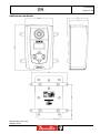
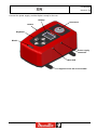
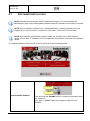
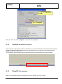
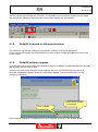
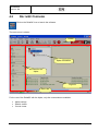
Part No. 6159938890 Issue 04 Date 05/2013 Page 1 / 87 ALPHA D1 / D5 / D16 WARNING To reduce the risk of injury, before using or servicing tool, read and understand the following information. The features and descriptions of our products are subject to change without prior notice. 1 (87) 4 11/2012 6159938890 Issue no. 04 Revision history Issue Date 01 10 January 2012 02 28 August 2012 03 14 November 2012 04 16 May 2013 Description Firmware version Minimum DeltaQC version First issue. 1.0x 2.0.x Curves added. 1.0x 2.1.x DeltaQC installation updated, overload management updated, transducer information and report added, default values updated. 1.2x 2.2.x Settings updated (par. 10). 1.3x 2.4.x NOTE: The programming software DeltaQC may be updated with no changes regarding the Alpha functionalities. The minimum version indicated here is required for the reference firmware version. Contents Contents .........................................................................................................................2 Safety Instructions .............................................................................................................5 1 Introduction ...........................................................................................................7 1.1 1.2 1.3 2 Overview .............................................................................................................. 11 2.1 3 Presentation ...........................................................................................................12 User Interfaces .................................................................................................... 14 3.1 3.2 3.3 3.4 3.5 4 About this Document ................................................................................................7 Specifications ...........................................................................................................8 Standard Conformity ...............................................................................................10 Display ....................................................................................................................14 Keyboard ................................................................................................................15 Transducer .............................................................................................................15 Buzzer ....................................................................................................................18 Mini USB port .........................................................................................................18 Working with DeltaQC Software ......................................................................... 19 4.1 Software Installation ...............................................................................................20 4.1.1 4.1.2 4.1.3 4.1.4 4.1.5 4.2 DeltaQC Overview ..................................................................................................36 4.2.1 4.2.2 4.3 4.4 4.5 5 Software registration ............................................................................................... 29 DeltaQC Evaluation version.................................................................................... 34 DeltaQC Free version ............................................................................................. 34 DeltaQC Licensed or Advanced versions ............................................................... 35 DeltaQC software upgrade ..................................................................................... 35 Toolbar .................................................................................................................... 37 Status bar................................................................................................................ 37 Settings in DeltaQC ................................................................................................38 Connecting to the Alpha..........................................................................................38 Alpha LOG File .......................................................................................................40 Getting Started with Alpha ................................................................................. 42 06/2013 2 (87) 6159938890 Issue no. 04 5.1 Executing a Demo Test...........................................................................................43 5.1.1 5.1.2 6 Testing Click-wrenches ...................................................................................... 45 6.1 Test Setup for Click-wrenches ................................................................................46 6.1.1 6.1.2 6.1.3 6.1.4 6.1.5 6.1.6 6.1.7 7 Test Setup for Nutrunner Test.................................................................................53 7.1.1 7.1.2 7.1.3 7.1.4 7.1.5 Test Setup for Pulse Tool Test................................................................................58 8.1.1 8.1.2 8.1.3 8.1.4 8.1.5 Testing Slip-wrenches.............................................................................................62 Test Setup for Peak Test ........................................................................................63 9.2.1 9.2.2 9.2.3 9.2.4 Measurement unit ................................................................................................... 63 Tightening direction ................................................................................................ 64 Timeout ................................................................................................................... 64 Cutoff frequency (Fcut) ........................................................................................... 65 Alpha Settings ..................................................................................................... 66 10.1 10.2 10.3 10.4 10.5 10.6 10.7 11 Measurement unit ................................................................................................... 59 Tightening direction ................................................................................................ 59 Timeout ................................................................................................................... 59 Threshold (THR 2) .................................................................................................. 60 Torque coefficient (K tuning)................................................................................... 60 Peak Test.............................................................................................................. 62 9.1 9.2 10 Measurement unit ................................................................................................... 53 Tightening direction ................................................................................................ 53 Timeout ................................................................................................................... 54 st nd 1 threshold and 2 threshold (THR 1 and THR 2) ............................................... 55 Cutoff frequency (Fcut) ........................................................................................... 56 Testing Pulse Tools ............................................................................................ 57 8.1 9 Measurement unit ................................................................................................... 47 Tightening direction ................................................................................................ 47 Timeout ................................................................................................................... 47 st 1 threshold (ITHR 1) ............................................................................................. 48 nd 2 threshold (ITHR 1) ............................................................................................. 49 Cutoff frequency (Fcut) ........................................................................................... 50 Result ...................................................................................................................... 50 Testing Nutrunners ............................................................................................. 51 7.1 8 Track ....................................................................................................................... 43 Peak ........................................................................................................................ 44 Language................................................................................................................66 Date and Time ........................................................................................................67 Demo Mode Measurement Unit ..............................................................................68 Alpha Name ............................................................................................................68 Result Confirmation ................................................................................................69 Information..............................................................................................................70 Memory ..................................................................................................................70 Results Viewer ..................................................................................................... 71 11.1 Export Results to Excel ...........................................................................................73 12 Curves Viewer...................................................................................................... 74 12.1 View One Curve......................................................................................................74 12.2 Copy, Print and Export a Curve ..............................................................................77 12.3 Curves Comparison ................................................................................................78 13 Maintenance......................................................................................................... 81 13.1 Yearly calibration ....................................................................................................81 13.2 Cleaning .................................................................................................................81 14 Troubleshooting Guide ....................................................................................... 82 14.1 Alpha Diagnostic .....................................................................................................82 3 (87) 11/2012 6159938890 Issue no. 04 15 Abbreviations ...................................................................................................... 83 06/2013 4 (87) 6159938890 Issue no. 04 SAFETY INSTRUCTIONS Important information for safe use These instructions concern installation, operation, handling and maintenance of product, inserted/mounted tool and equipments. • It is vital that the operator has read and carefully understood the instructions before using this product. • Keep instructions safe for future reference and make sure that the operator has complete access to them. • Failure to follow these instructions may cause serious hazard. Our goal is to produce tools that help you work safely and efficiently. The most important safety device for this and for any tool is YOU. Your care and good judgment are the best protection against injury. This tool must be not modified for product liability and safety reason. Only qualified and trained operators should install, adjust or use this tool. All possible hazards cannot be covered here, but we highlight some of the most important. For additional safety information consult: • Other documents and information packed with this tool. • Your employer, union and/or trade association. • Appropriate standards as referred to in the section EC Declaration of Conformity. Further occupational health and safety information can be obtained from the following web sites: http://www.osha.gov (USA) http://www.osha.eu.int (Europe) Safety signal words The safety signal words Danger, Warning and Caution have the following meaning: DANGER Indicates a hazardous situation which, if not avoided, will result in the death or serious injury. WARNING Indicates a hazardous situation which, if not avoided, could result in the death or serious injury. CAUTION Indicates a hazardous situation which, if not avoided, could result in minor or moderate injury. 1. Personal precautions and qualifications 1.1 Installation, storage, maintenance and disposal Installation, storage, maintenance and disposal of the product may only be undertaken by person who: • Are physically able to handle the bulk and weight of the tool. • Are aware of all the relevant national safety instructions and accident prevention instructions. • Have read and understood the operating instructions. 5 (87) 11/2012 6159938890 Issue no. 04 1.2 Operation Operation of the product may only be undertaken by person who: • Are physically able to handle the bulk and weight of the tool. • Are trained to operate the product in conformity with national directives. • Are aware of all the relevant national safety instructions and accident prevention instructions. • Have read and understood the operating instructions. 1.3 Drugs, alcohol and medication Drugs, alcohol and medications may impair your judgment and powers of concentration. WARNING: Poor reactions and incorrect assessment can lead to serious accidents or death • • Never operate the product when you are under the influence of drugs, alcohol or medication Prevent other people from using the product if they are under the influence of drugs, alcohol or medication 2. General information 2.1 Intended use The Alpha is intended as measurement instrument to be used to test nutrunners and wrenches, and to make quality tests on joints. The product, its attachments and accessories must be only used for this purpose for which they were designated. All other use is prohibited. 3. Installation AC Power The power supply works with AC Power (110 ÷ 240 VAC). WARNING: AC voltage can cause serious injury • • 4. Connect the AC power from a power supply line properly grounded and protected. Never open and/or modify the battery charger. Operations Correct working with the Alpha WARNING: Failure to follow correct working practices cause result in serious injury or death • • • Ensure that the workpiece is properly supported. There is a risk of electrostatic discharge if the tool is used on plastic and other non-conductive materials. Maintain a balanced body position and firm footing. 06/2013 6 (87) 6159938890 Issue no. 04 1 Introduction 1.1 ABOUT THIS DOCUMENT This document is a user manual for the Alpha D1 / D5 / D16 and it is divided into the main following parts: Part Name Description Chapter 1 Introduction This part introduces this user manual and details the Alpha technical specifications. Chapter 2 System Overview This part introduces the Alpha with its modules and accessories. Chapter 3 User Interfaces This part provides an overview of the user interfaces available on the Alpha (LEDs, display, keyboard, etc). Chapter 4 Working with DeltaQC This part introduces the operations of the Alpha management software. Chapter 5 Getting started with Alpha This part guides the operator in starting to use the Alpha. Chapter 6, 7, 8 and 9 Testing click-wrenches, testing nutrunners, peak detection test, testing pulse tools These chapters explain in details how to conduct a test on the various tools types. Chapter 10 Alpha settings This part covers the instrument settings. Chapter 11 and 12 Results viewer and Curves viewer These chapters explain how to retrieve results and curves from the Alpha. Chapter 13 and 14 Maintenance and Troubleshooting guide These chapters are dedicated to the instrument maintenance and troubleshooting Chapter 15 Abbreviations Table of the abbreviation used in this manual. 7 (87) 11/2012 6159938890 Issue no. 04 1.2 SPECIFICATIONS TECHNICAL • Torque range: - Alpha D1: 0.05 ÷ 1 Nm - Alpha D5: 0.25 ÷ 5 Nm - Alpha D16: 0.8 ÷ 16 Nm • Torque static accuracy: • • • • • • ±1% of the applied torque (between 20% and 100% of the FSD) Torque overload capacity: 25% of FSD Stability of zero offset with temperature: ±0.1% of FSD/ºC Unit of measurement supported: N∙m, Kgf∙m, Kgf∙cm, lbf∙ft, lbf∙in, ozf∙ft, ozf∙in, Kp∙m, dN∙m Results memory capacity: 1000 Curves memory capacity: 10 curves, 30 s length each maximum Sampling frequency: - Free mode (track and peak): 1 kHz - Click-wrench test: 2 kHz - Nutrunner test: 4 kHz - Peak test: 1 kHz - Pulse tool test: 4 kHz EXTERNAL POWER SUPPLY • Input power: 100 ÷ 240 VAC, 50 ÷ 60 Hz • AC Power Consumption: 21 W maximum • Output: 6VDC, max 2.2A 06/2013 8 (87) 6159938890 Issue no. 04 DIMENSIONS AND WEIGHT Dimensions are in mm. Weight: 950 g 9 (87) 11/2012 6159938890 Issue no. 04 ENVIRONMENTAL The following conditions must be observed during operation: • Internal Use only • Environmental Class: II • IP Grade according to EN IEC 60529: IP40 • Ambient Temperature: 5 to 40°C • Atmospheric humidity: 95%, non-condensing • Altitude: up to 2000m INTERFACES • MiniUSB 2.0 port SYSTEM REQUIREMENTS The following are the PC minimum requirements for installation of the management software DeltaQC: • • • • • • • • Processor: 400 MHz (800 MHz or above recommended) Memory: 256 MB or above Hard disk space: 10 GB Display: 800 x 600, 256 colors (1024 x 768, High Color (16-bit) recommended) Operating Systems: Windows Server 2003; Windows XP; Windows Vista; Windows 7 Internet Explorer 5.01 or later (required for installation of the .NET Framework) Windows Installer 3.1 Microsoft Excel (required to view the exported file with the tightening results) Note: a system should meet these or the minimum requirements for the operating system, whichever is higher CALIBRATION CERTIFICATE Alpha is provided with a Desoutter factory calibration certificate. 1.3 STANDARD CONFORMITY The Alpha is in conformity with the requirements of the council Directives on 06/22/1998 on the approximation of the laws of the Member States relating: • 2004/108/CE • 2006/95/CE 06/2013 EMC Directive - Electromagnetic Compatibility Low Voltage Directive 10 (87) 6159938890 Issue no. 04 2 Overview Power supply DeltaQC PC Alpha The Alpha D1 / D5 / D16 are instruments designed for optimal operations in: • Tools testing: the Alpha offers a set of tests for evaluating click-wrenches, slip-wrenches, nutrunners and pulse tools, measuring the torque values and producing results with statistical parameters. This makes possible to keep the quality of the tightening operations on a production line under control. The test results can be retrieved by the Alpha management software (DeltaQC), and exported then into Microsoft Excel. The D1, D5 and D16 indicate the instrument torque capacity: • D1 → 1 Nm • D5 → 5 Nm • D16 → 16 Nm 11 (87) 11/2012 6159938890 Issue no. 04 2.1 PRESENTATION The Alpha is composed by the following parts: Alpha D1 / D5 / D16 The main part, which contains all the hardware and firmware. Power Supply Power supply for the Alpha. DeltaQC The Alpha management software. It allows Alpha configuration and retrieving results and curves from the instrument. Mechanical joint simulators Two joint simulators are provided with the Alpha: one to simulate a soft joint and one a hard joint. Soft Hard Supports The supports are useful to fix the Alpha to a table. The screws are included with the package. 06/2013 12 (87) 6159938890 Issue no. 04 Connect the power supply, and the Alpha is ready for the use: Display Transducer Buzzer Keyboard Model Power supply connector Mini USB Supports to fix the unit to a table 13 (87) 11/2012 6159938890 Issue no. 04 3 User Interfaces 3.1 DISPLAY The Alpha display allows to explore the menus, and monitoring torque during the tightening operation: Test type Tightening direction Torque Statistics Test type Indicates the test type. Tightening directions Indicates whether tightening must be done in the clockwise or counterclockwise direction. Torque Indicates the current measurements. Statistics Indicates minimum and maximum and average values, and standard deviation. For pulse tools, also the frequency of the pulses is shown. They are reset when exit and the test window. The display background color changes according to the tightening phase and result: White Default color for all the menus and settings Blue When a test is started, the display is backlight in blue. Green During the test execution, the display turns green when the result is OK. Red Color used to indicate error. During the test execution, the red color is used to indicate that torque value exceeds the maximum limit. NOTE: For better printing contrast, and for black/white printing, in this manual the display figures are always shown in yellow. 06/2013 14 (87) 6159938890 Issue no. 04 3.2 KEYBOARD Use the keyboard to browse the Alpha menu: Icon Name ON, OK Switch on the DWTA, enter menu and confirm. OFF, CL Switch off the DWTA, exit menu UP DOWN 3.3 Description Up (browse menu), increase value in settings menus. Down (browse menu), decrease value in settings menus. TRANSDUCER Transducer The Alpha features a torque static transducer installed on the unit. Simply select the test menu on the display and operate the tool on the transducer. The capacity is: • • • 15 (87) Alpha D1: 1 Nm Alpha D5: 5 Nm Alpha D16: 16 Nm 11/2012 6159938890 Issue no. 04 The transducer data can be viewed/set from the menu. Connect the power supply and switch on the unit by pressing the ON button. Scroll the main menu using the Up/Down arrow buttons and select the Transducer Info menu: To edit a parameter, press the OK button to edit the value, adjust the value by pressing the Up/Down buttons, and click on OK to save (or CL to exit). Capacity (Nm) Torque capacity of the Alpha. This value cannot be modified. Min Load (%) Minimum torque value from which the Alpha start measuring the torque values; the recommended value is 5%. It can be set from 1% to 5%. Overload (%) This parameter specifies the maximum torque applicable to the transducer as percentage of the Capacity value. It can be set from 90% to 125%. If the torque goes over the overload value, a warning message on the Alpha display advices the user, and it is shown again each time the Alpha is switched on; to reset the overload event, the Alpha must be recalibrated. Information and report about the Alpha transducer can be viewed from the DeltaQC software (see the Working with DeltaQC software chapter for software installation and usage). Connect the DeltaQC to the Alpha and select the Connected transducer menu: 06/2013 16 (87) 6159938890 Issue no. 04 Transducer info The Min Torque is calculated multiplying the Nominal torque by the Min Load (%) set in the Alpha as explained above. The Overload torque is calculated multiplying the Nominal torque by the Overload (%) set in the Alpha as explained above. Select the Report folder to view the report: The toolbar in the area above the report provides function to print or export the report into an Excel or PDF file. 17 (87) 11/2012 6159938890 Issue no. 04 3.4 BUZZER Along with the onboard LEDs, the Alpha has also a buzzer, to give more indications on the result of the current operation. A high tone is emitted in case of OK result, while a lower tone is emitted in case of test Not OK. For details, see the specific chapters for various tests available on the Alpha. 3.5 MINI USB PORT USB port The USB port is available for programming the Alpha with DeltaQC software. See the Connecting to the Alpha chapter for details. It allows also firmware upgrade (reserved for Desoutter service personnel). 06/2013 18 (87) 6159938890 Issue no. 04 4 Working with DeltaQC Software DeltaQC is a PC software package developed to manage the Alpha. It offers easy user-friendly programming and real time monitoring of the instrument. DeltaQC serves as an interface between the user and the Alpha. With DeltaQC, users can configure the Alpha, and receives the results and curves. The main features are: • • 19 (87) Review of results and curves from the Alpha Settings of the Alpha 11/2012 6159938890 Issue no. 04 4.1 SOFTWARE INSTALLATION NOTE: Installation must be done with PC administrator rights. To run the software the administrator rights (or the administrator password when the software is launched) is required. NOTE: Do not install the software from a shared folder/drive. Install the software from the supplied CD; if the CD content is copied into a PC folder, it must be a PC local folder. NOTE: After installing the DeltaQC software, install also the SQL Server 2005 express edition, service pack 3. Installation file is provided with the DeltaQC. See below for installation details. To install the software, insert the CD in the PC and wait for the following window: ReadMe Install Install DeltaQC Software Click and read the ReadMe file first, containing information about the installation. Click then on Install to start the installation wizard for the DeltaQC. 06/2013 20 (87) 6159938890 Issue no. 04 View User Manual Open the DeltaQC User Manual in PDF. Contact US Shows the Desoutter contact details. Register DeltaQC Software Provide the link to register the DeltaQC. Registration must be done after the installation. See the end of this chapter for registration details. 21 (87) 11/2012 6159938890 Issue no. 04 If the window shown above is not shown automatically, explore the CD and select StartCD.vbs: Follow the installation steps described below: These first two messages are shown or not depending on the Microsoft Explorer settings 06/2013 22 (87) 6159938890 Issue no. 04 Enter your information Default installation folder (recommended) If the next message is shown during the installation, click on Continue Anyway: If SQL Server 2005 is not present in the PC, the following window alerts the user that it needs to be installed; in this case a shortcut to the SQL Server 2005 installation is created automatically on the desktop of the PC. 23 (87) 11/2012 6159938890 Issue no. 04 See below for how to install SQL Server 2005 Turn on the Alpha and wait until initialization has finished and the main menu appears on the Alpha display. Connect the Alpha to the PC through the USB cable and the new hardware setup wizard is shown: Select No, not this time 06/2013 Select Install the software automatically 24 (87) 6159938890 Issue no. 04 Select Continue The installation of the DeltaQC provides also the SQL Server installation file. Even if the PC where the DeltaQC is installed already has SQL Server, it is recommended to install the version included with the DeltaQC installation package. To install SQL Server 2005 double-click on the shortcut created by the installation wizard, and follow the setup procedure: NOTE: Some antivirus programs may interfere with the installation wizard while extract the files. In that case the installation procedure ends with an error. The antivirus should be temporary disabled to perform the installation. 25 (87) 11/2012 6159938890 Issue no. 04 Enter your information The next window changes if the SQL Server is already installed or not on the PC. The installation process automatically selects the correct option (in the first case, just rename the instance as shown in the next figure): If SQL Server is already installed, the “Named instance” is selected (write DELTAQC here) 06/2013 If SQL Server is not already installed, the “Default instance” is selected. 26 (87) 6159938890 Issue no. 04 27 (87) 11/2012 6159938890 Issue no. 04 After installation, the program is added to the Start → Program → Desoutter → DeltaQC menu (a desktop icon is created as well). After installing the software you need to register it (see the next paragraph of this chapter for details). The first time the Alpha is connected to the PC, the following windows are shown. Follow the steps as shown: Select “Install automatically” Select “No, not this time” 06/2013 28 (87) 6159938890 Issue no. 04 4.1.1 Software registration The first time the software is executed, the following window is shown: Public KEY Click to register Registration instructions Click on Continue in demo mode to skip the registration and working in demo mode (the registration can be done at a later time). To proceed with the registration, take note of the Public KEY given in the form above, and click on the link https://licensing.desouttertools.com 29 (87) 11/2012 6159938890 Issue no. 04 The following window is shown: Login or create a new account. If not already created, create a new account: Submit 06/2013 30 (87) 6159938890 Issue no. 04 Enter your information and click on Submit. A confirmation message is shown: On the email address given in the account above, a link is sent. Click on the link provided. Click to login Click on Home and it is possible now to login: Login On the following window, select License Management (from the same window is also possible to edit the profile information or to open the Desoutter contact form): 31 (87) 11/2012 6159938890 Issue no. 04 License management Contact Desoutter Edit profile Enter the Serial number and the Key provided on the installation CD: Serial number written on the CD Key written on the CD Click on Submit and the following window is shown: Add 06/2013 32 (87) 6159938890 Issue no. 04 Click on Add to proceed with the registration (or on Delete to delete the serial number and key already entered): Public key PC name Enter the Public key generated by the DeltaQC registration form and the PC name (choose any name) and click on Submit to get the registration code: Registration code Copy the registration code in the DeltaQC registration form and click on Register to complete the registration: 33 (87) 11/2012 6159938890 Issue no. 04 Enter the Registration code Click on Register Enter the code and click to Register to complete the registration. 4.1.2 DeltaQC Evaluation version If the software is not registered after the installation, it works as Evaluation for 90 days; the Evaluation version provides all of the functionality of the registered version. When the trial period expires the software turns into Free version. The number of days remaining for the trial period is shown in the bottom part of the software: 4.1.3 DeltaQC Free version When the trial period expires the software turns from “demo” into “free” version. 06/2013 34 (87) 6159938890 Issue no. 04 The free version has a limited set of function: It is possible only to review the results from the Alpha and perform the settings of the instrument; all the other features are not available. 4.1.4 DeltaQC Licensed or Advanced versions It is possible to register the software in two different versions: Licensed or Advanced. For the use with the Alpha, the Advanced and Licensed version provide the addition function of the curves viewer. 4.1.5 DeltaQC software upgrade In case a new version of the software is available, the new installation wizard automatically overwrites and upgrades the previous version. In case of the new version features a new database structure, the first time the new version is launched a database migration wizard is automatically started. Click on start and wait until the process is completed: Wait until the process is completed Click on Start Ensure that the Migration completed with success! message is shown in the window above. 35 (87) 11/2012 6159938890 Issue no. 04 4.2 DELTAQC OVERVIEW Click on the DeltaQC icon to launch the software. The main menu is shown: Toolbar Alpha information Not used for the Alpha Log area Status bar For the use of the DeltaQC with the Alpha, only few commands are available: • • • Alpha settings Results viewer Curves viewer 06/2013 36 (87) 6159938890 Issue no. 04 4.2.1 Toolbar The toolbar icons are shortcuts to the functions in DeltaQC. Icon Icon name Description Controller This icon opens the Controller programming section; use the arrow to the right of the icon to select one of the sub-menus. Controller contains information and settings for Alpha. See the Alpha Settings chapter for more information. Results Viewer This icon opens the Results Viewer page. Curves Viewer See the Results viewer chapter for more information. This icon opens the Curves Viewer page. See the Curves viewer chapter for more information. Connect Establish the connection between the Alpha and the PC (the icon is disabled when the device is already connected). See the Connecting to the Alpha chapter for more information. Disconnect 4.2.2 Once a connection is established this icon gets active. Click to disconnect the PC from the Alpha. Status bar The status bar shows when the Alpha is connected to the DeltaQC. 37 (87) 11/2012 6159938890 Issue no. 04 4.3 SETTINGS IN DELTAQC You can set the language from the Options → Change language menu: After changing the language, restart the software to make the change effective. 4.4 CONNECTING TO THE ALPHA The connection between the DeltaQC and the Alpha is performed via USB cable. If you are connecting the Alpha to the PC with the software for the first time, select Scan: Scan 06/2013 38 (87) 6159938890 Issue no. 04 Click on Scan Select the Alpha Click on Select This operation is necessary only once. After the first time, perform the following sequence: • • • • Launch the DeltaQC. Turn on the Alpha and wait for the Alpha to power on (the main menu is shown on the display) Connect the Alpha to the PC through USB cable (with the Alpha already turned on) Select Alpha, and click on the arrow of the Connect icon and select USB to connect to the instrument: Connect icon 39 (87) 11/2012 6159938890 Issue no. 04 It is also possible to double-click on icon in the Alpha map: 1. Right-click 2. Select USB When the Alpha is connected, the Connect icon is disabled, the Disconnect icon becomes active, and the Alpha Map is shown: Online Disconnect icon Online 4.5 ALPHA LOG FILE The log viewer function allows to obtain information about the Alpha – DeltaQC communication. However, this function is more helpful when working with devices creating tightening programs from the software and transferred to the online device. Enable the log area: Enable Log area 06/2013 40 (87) 6159938890 Issue no. 04 The messages related to Alpha – DeltaQC communication are displayed in the log area: Log messages A log file is automatically created in a subfolder of the installation directory of the DeltaQC, typically: C:\Program Files\Desoutter\DeltaQC\Log A new file is created each day the software is used; the old files can be deleted is no longer needed. 41 (87) 11/2012 6159938890 Issue no. 04 5 Getting Started with Alpha To turn on the Alpha, connect the power supply to the Alpha, then press the ON button on the keyboard; to turn it off, press again the ON button and hold it down for few seconds. The power on screen will appear for few seconds; the Alpha firmware version is displayed: Alpha firmware version Power on screen Torque zero adjustment Do not apply any torque to the transducer during the power on phase, as the instrument needs to execute a zero procedure for proper operations. After the power on screen, the main menu is shown on the display: Demo Mode Enters the demo mode (Track and Peak functions). Measurement Conducts a test on a tool. Measurement Setup Defines the setup parameters for the click-wrenches test, nutrunners test, pulse tools, and peak test. Settings Customizes the Alpha settings. Transducer Info Information about the Alpha capacity, minimum load and overload capacity. The minimum load and the overload value can be set from this menu. 06/2013 42 (87) 6159938890 Issue no. 04 5.1 EXECUTING A DEMO TEST The demo mode conducts a test (track or peak mode) simply accessing the Alpha from the keyboard without the need to set the test. NOTE: In this mode the results are not saved in the Alpha memory. To execute the test, select Demo Mode from the main menu: The measurement unit for the demo mode can be chosen in the Settings menu. 5.1.1 Track This mode tracks the torque in real time. Torque Time In track mode, the Alpha simply displays the applied torque in real time. Torque can be applied in either the clockwise (positive torque) or counter-clockwise (negative torque) direction. By clicking on the OK button on the keyboard the Alpha executes a torque zero adjustment. Note that this zero adjustment will be applied only for this test and not applied as a global zero reference. The cutoff frequency for this test is 100 Hz. 43 (87) 11/2012 6159938890 Issue no. 04 5.1.2 Peak In this mode the torque applied to the Alpha transducer is shown in real time, and the maximum value reached during tightening remains frozen on the Alpha display. Torque Displayed Torque Applied Torque Min. Load Time The Alpha displays torque in real time, starting from the minimum load of the Alpha, and the peak value is frozen on the display: A new cycle starts when the applied torque is released, and applied again over the minimum load of the Alpha. By clicking on the OK button on the keyboard the torque value is reset. The torque must be applied in the clockwise direction. The cutoff frequency for this test is 100 Hz. 06/2013 44 (87) 6159938890 Issue no. 04 6 Testing Click-wrenches The goal of this test is to detect the “click-point” of the wrench: Torque Click-point Time The click-point is detected when the torque drops and then increases again, producing thus the typical shape of the “click” phenomenon, as shown in the two examples following: Click-point Click-point If the torque only drops to zero (without increasing again) after a peak point (as shown in the next figure), that is not detected as click point. For this reason, slip-wrenches cannot be tested with this method (slip-wrenches should be tested with the peak-wrench function): Torque This point will be not detected as click point. Time If the test ends and the click-point is not detected, a message “not detected” is shown on the display. In that case the result is the torque absolute peak. 45 (87) 11/2012 6159938890 Issue no. 04 To execute the test, select Measurement → Click Wrench from the main menu: During the test, the torque result and statistics are displayed: The display backlight is colored as follows: Blue Default color used for Pset execution. Green The display turns green if the click-point is detected. Red Click-point not detected or torque over the overload value. The buzzer is activated as follows: Buzzer 6.1 Three high tones if the click-point is detected, lower tone if the click-point is not detected. TEST SETUP FOR CLICK-WRENCHES Regulating the click-wrench test parameters is important to adjust and customize the test process. Entered the Measurement Setup → Click Wrench Setup menu: The following screen is displayed: 06/2013 46 (87) 6159938890 Issue no. 04 Scroll the parameters by using the UP/DOWN buttons, and press OK to edit. Finally, press OK again to confirm the new value, or CL to quit without saving. 6.1.1 Measurement unit Select the desired measurement unit. 6.1.2 Tightening direction Select one of the following options: CW : The test must be executed in the clockwise direction. CCW : The test must be executed in the counter clockwise direction. CW/CCW: The test can be executed in both the directions. When the torque goes over the minimum load, the test will be started considering positive the torque in the direction of the torque applied. 6.1.3 Timeout The timeout defines the end of the test. When the torque goes and remains below the transducer minimum load (which is the 5% of the transducer full scale) for the given timeout, the test will end. Torque Transducer full scale The test ends when torque remains under the transducer minimum load for the timeout. Transducer min. load Time Timeout Timeout If torque goes over transducer minimum load before the timeout, the test continues. 47 (87) 11/2012 6159938890 Issue no. 04 Timeout can be set from 100 ms up to 2000 ms. The default value is 100 ms. 6.1.4 1st threshold (ITHR 1) The 1st threshold is used to detect the click point of the wrench. To be considered as the click point, the torque must continuously decrease at least by the specified value from the measured peak. The default value is 5%, and it is calculated on the relative torque peak value reached: Torque Click point st 1 threshold If torque goes below the 1st threshold, the clickpoint is detected. Time For instance, if the peak is 100 Nm and the threshold is set to 5%, the torque must go under 95 Nm. The default value suits many of the click-wrenches, but it might be necessary to adjust it according to the specific wrench you are testing. If the click-point produces a big drop in the torque, this threshold can be increased, to avoid detecting false click points at lower toque values: False click, not detected. If the click produces a big torque drop, the 1st threshold can be increased. On the other side, if the click-point produces only a little drop in the torque, this threshold should be decreased in order to detect the click-point: 06/2013 48 (87) 6159938890 Issue no. 04 False click, which may be detected as the clickpoint!! If the click produces a little torque drop, the 1st threshold should be decreased. Note that decreasing the threshold increases the risk to detect false click-points. To summarize, the 1st threshold should be set not too low to avoid the detection of false click, but not too high to not detecting the real click-point. 6.1.5 2nd threshold (ITHR 1) The 2nd threshold is used to exclude from the analysis all the part of the curve below a certain value, where false click may occur if the operator movement would be not enough steady. The default value is 70%, and it is calculated on the maximum torque value reached during the test. Under the specified threshold the torque is not considered by the Alpha. Torque Max. torque nd 2 threshold Time NOTE: The all “click” phenomenon, including the point when the torque starts increasing again after the “click”, must be over the 2nd threshold. If not, the click point is not detected: 49 (87) 11/2012 6159938890 Issue no. 04 Torque nd 2 threshold In this case the click point will be not detected. Time 6.1.6 Cutoff frequency (Fcut) The cutoff frequency can be set to 100, 200, 500 or 1000 Hz. This is applied to the samples measured by the torque transducer to filter the noise. The default value is 100Hz, which is a convenient value for most of the click-wrenches; however, it may be necessary to increase the value for wrenches having a click-point very “fast”, or decrease in cases where the noise in the measurement is too strong and interferes with the click-point detection. 6.1.7 Result This defines which peak must be taken as torque result. If the Peak Click is selected, the first peak (click-point) will be taken as result of the test; otherwise, if the Abs. Peak is selected, the maximum torque will be taken as result. Torque If the Result is the Peak Click, this point is the result. If the Result is the Abs. Peak, this point is the result. nd 2 threshold Time 06/2013 50 (87) 6159938890 Issue no. 04 7 Testing Nutrunners By “nutrunners” we mean all those tools providing real torque to the joint, like battery tools, pneumatic tools (not impulse) and electronic controlled tools. For nutrunner test, the torque result shown by the Alpha is the peak value measured during the test. Torque Time In case of multiple peaks, the result will be the first peak. To be detected as a peak, the peak must satisfy the two thresholds specified. See the next paragraphs of this chapter for details. 51 (87) 11/2012 6159938890 Issue no. 04 To test a power tool on the Alpha, a mechanical joint simulator must be used in order to let the tool rotating: Joint simulator Joint simulator To execute the test, select Measurement → Nutrunner from the main menu: During the test, the torque result and statistics are shown: The display backlight is colored as follows: Blue Default color used for Pset execution. Green The display turns green if the peak-point is detected. Red Peak-point not detected or torque over the overload value. The buzzer is activated as follows: Buzzer 06/2013 Three high tones if the peak-point is detected, lower tone if the peak-point is not detected. 52 (87) 6159938890 Issue no. 04 7.1 TEST SETUP FOR NUTRUNNER TEST Regulating the nutrunner test parameters is important to adjust and customize the test process. Entered the Measurement Setup → Nutrunner menu: The following screen is displayed: Scroll the parameters by using the UP/DOWN buttons, and press OK to edit. Finally, press OK again to confirm the new value, or CL to quit without saving. 7.1.1 Measurement unit Select the desired measurement unit. 7.1.2 Tightening direction Select one of the following options: 53 (87) CW : The test must be executed in the clockwise direction. CCW : The test must be executed in the counter clockwise direction. CW/CCW: The test can be executed in both the directions. When the torque goes over the minimum load, the test will be started considering positive the torque in the direction of the torque applied. 11/2012 6159938890 Issue no. 04 7.1.3 Timeout The timeout defines the end of the test. When the torque goes and remains below the transducer minimum load (which is the 5% of the transducer full scale) for the given timeout, the test ends. Torque Transducer full scale The test ends when torque remains under the transducer minimum load for the timeout. Transducer min. load Time Timeout For two-steps tools, it allows the tool to switch between the two steps without ending the test. Torque Transducer full scale If torque goes over transducer minimum load before the timeout, the test continues. Transducer min. load Time Timeout Timeout Timeout can be set from 100 ms up to 2000 ms. The default value is 100 ms. 06/2013 54 (87) 6159938890 Issue no. 04 7.1.4 1st threshold and 2nd threshold (THR 1 and THR 2) The two thresholds are used to setup the test for the type of tool under test. The 1st threshold used to detect the peak value of the torque; the torque must continuously decrease at least by the specified value from the measured peak. It is calculated on the relative torque peak. The default value is 5%. The 2nd threshold is used to exclude from the analysis all the part of the curve below a certain value, where there may be noise in the curve. The default value is 90%, and it is calculated on the maximum torque value reached during the test. Under the specified threshold the torque is not considered by the Alpha. Torque Max. torque st 1 threshold nd 2 threshold Time For instance, if the peak is 100 Nm and the threshold is set to 5%, the torque must go under 95 Nm. For a generic nutrunner these settings should be not critical, and the default value should suit almost all of the tools. For quickstep or two-steps tools, the 2nd threshold is used to exclude the first step from the measurement; if not set properly, the peak of the first step is taken as result of the test: Torque Max. torque st 1 threshold nd 2 threshold The 2nd threshold must be higher than the peak of the first step! First step Second step Time 55 (87) 11/2012 6159938890 Issue no. 04 7.1.5 Cutoff frequency (Fcut) The cutoff frequency can be set to 100, 200, 500, or 1000. This is applied to the samples measured by the torque transducer to filter the noise. The default value is 500 Hz. It may be necessary to increase the value for certain tools where the default value does not suit the specific tool characteristics. 06/2013 56 (87) 6159938890 Issue no. 04 8 Testing Pulse Tools Pulse tools provide a series of pulses to tighten the joint. A pulse tool can be tested on Alpha. If the pulse tool has the shut-off valve, one of the two mechanical joint simulator provided with the Alpha must be used: Torque No shut-off tool Time Torque Shut-off tool Joint simulator Time WARNING: Impact tools cannot be tested on the Alpha. 57 (87) 11/2012 6159938890 Issue no. 04 To execute the test, select Measurement → Pulse Tool from the main menu: During the test, the torque result, statistics and pulse tool frequency are displayed: The cutoff frequency for pulse tools test is 2 kHz. The display backlight is colored as follows: Blue Default color used for Pset execution. Green The display turns green if the result is within the transducer overload. Red Torque over the overload value. The buzzer is activated as follows: Buzzer 8.1 Three high tones advice the user about the end of the test. TEST SETUP FOR PULSE TOOL TEST Regulating the pulse tool test parameters is important to adjust and customize the test process. Entered the Measurement Setup → Click Wrench Setup menu: The following screen is displayed: 06/2013 58 (87) 6159938890 Issue no. 04 Scroll the parameters by using the UP/DOWN buttons, and press OK to edit. Finally, press OK again to confirm the new value, or CL to quit without saving. 8.1.1 Measurement unit Select the desired measurement unit. 8.1.2 Tightening direction Select one of the following options: CW : The test must be executed in the clockwise direction. CCW : The test must be executed in the counter clockwise direction. CW/CCW: The test can be executed in both the directions. When the torque goes over the minimum load, the test will be started considering positive the torque in the direction of the torque applied. 8.1.3 Timeout When the torque goes and remains below the transducer minimum load (which is normally the 5% of the transducer full scale) for the given timeout, the test will end. Torque Transducer full scale The test ends when torque remains under the transducer minimum load for the timeout. Transducer min. load Time Timeout Timeout Timeout can be set from 100 ms up to 2000 ms. The default value is 100 ms. 59 (87) 11/2012 6159938890 Issue no. 04 8.1.4 Threshold (THR 2) The threshold is used to filter the curve for proper peak detection for the frequency calculation. After each peak is detected, all the values under the threshold will be discarded. This will filter all the bounces always present in a pulse tightening The default value is 80%. Peak Peak Torque Peak Time Bounces 8.1.5 Bounces Torque coefficient (K tuning) Pulse tools do not provide a continuous torque output, but they generate single high energy pulse of very short duration (≈ 1ms). This series of pulses results in the tightening of a fastener. Due to the physics of the tool the final torque reached cannot be measured directly as for real torque tools. The reason for this is that pulse tools provide a very high torque for such a short time that only a part of these peaks translate into the tightening of the fastener (generating more clamping force). This depends on many factors such as the bolt mass, friction, the stiffness of the joint, etc... The torque coefficient is used to align the torque measured by the transducer with the real torque produced on the joint. The torque produced on the real joint will be always less (ideally equal) than the peak torque measured on the transducer. Therefore, this coefficient can be set to values between 500 and 1000 (the value is entered in thousandths, therefore 500 corresponds to 0.500 and 1000 correspond to 1.000). 06/2013 60 (87) 6159938890 Issue no. 04 Torque Peak value measured on the torque transducer. Actual torque measured on the joint. Time The only way to evaluate the actual torque is to make a residual torque check on the real joint. The relation between the peak torque measured on the transducer and the actual torque on the joint is affected by all the components: The pulse tool, the adapters, the transducer, and the joint itself. If any of these components is changed, the relation peak torque – actual torque should be recalculated. The following process should be used to adjust the pulse tool in order to provide the desired torque on the real joint and to calculate the proper coefficient K: Set a low torque Check the residual torque OK Too low Slightly increase torque For instance, assume a target torque for the joint of 100 Nm, and after the tool regulation the residual torque check gives 100 Nm; if the torque measured on the transducer is 120 Nm, in that case the coefficient will be 100/120 = 0.83 → 830. 61 (87) 11/2012 6159938890 Issue no. 04 9 Peak Test The peak test provides the maximum torque measured during the test. The typical application of this method is the test of slip-wrenches, described in the next paragraph. 9.1 TESTING SLIP-WRENCHES The “slip-point” point is the peak value of the curve. Torque Slip-point Time The torque result is the peak value measured during the test. To execute the test, select Measurement → Peak from the main menu: During the test, the torque result and statistics are displayed: 06/2013 62 (87) 6159938890 Issue no. 04 The cutoff frequency for peak detection test is 100 Hz. The display backlight is colored as follows: Blue Default color used for Pset execution. Green The display turns green if the test ends within the transducer overload. Torque over the overload value. Red The buzzer is activated as follows: Buzzer 9.2 Three high tones advice the user about the end of the test. TEST SETUP FOR PEAK TEST Regulating the pulse tool test parameters is important to adjust and customize the test process. Entered the Measurement Setup → Click Wrench Setup menu: The following screen is displayed: Scroll the parameters by using the UP/DOWN buttons, and press OK to edit. Finally, press OK again to confirm the new value, or CL to quit without saving. 9.2.1 Measurement unit Select the desired measurement unit. 63 (87) 11/2012 6159938890 Issue no. 04 9.2.2 Tightening direction Select one of the following options: CW : The test must be executed in the clockwise direction. CCW : The test must be executed in the counter clockwise direction. CW/CCW: The test can be executed in both the directions. When the torque goes over the minimum load, the test will be started considering positive the torque in the direction of the torque applied. 9.2.3 Timeout The timeout defines the end of the test. When the torque goes and remains below the transducer minimum load (which is the 5% of the transducer full scale) for the given timeout, the test will end. Transducer full scale The test ends when torque remains under the transducer minimum load for the timeout. If torque goes over transducer minimum load before the timeout, the test continues. Transducer min. load Time Timeout Timeout Timeout can be set from 100 ms up to 2000 ms. The default value is 100 ms. NOTE: For slip-wrenches, the operator should operate the wrench until the slip point is reached, and stop rotating the wrench after. With the timeout default value, if the operator continues to rotate the wrench producing more slips, each of them will produce a test results: With default short timeout, both of the two points will produce a result. 06/2013 Setting a longer timeout, only the higher of the two points will produce a result. 64 (87) 6159938890 Issue no. 04 9.2.4 Cutoff frequency (Fcut) The cutoff frequency can be set to 100, 200, or 500 Hz. This is applied to the samples measured by the torque transducer to filter the noise. The default value is 100 Hz. It may be necessary to increase the value for certain tools where the default value does not suit the specific tool characteristics. 65 (87) 11/2012 6159938890 Issue no. 04 10 Alpha Settings 10.1 LANGUAGE To set the display language, select Settings → Language from the main menu: Select the language and confirm with the OK button on the keyboard. The language can be also set by the DeltaQC software, by selecting the Controller → Configuration menu: 06/2013 66 (87) 6159938890 Issue no. 04 10.2 DATE AND TIME Select the Insert Date-Time menu: Use the right/left arrows on the keyboard to choose the field to edit, and use the up/down arrows to increase/decrease the selected field. To select between European and American date format, select Settings → Date menu. The date and time can be also set by the DeltaQC software, by selecting the Controller → Configuration menu: Click here to set to the Alpha the same date-time of the PC. 67 (87) 11/2012 6159938890 Issue no. 04 10.3 DEMO MODE MEASUREMENT UNIT Select the Demo mode unit menu: Select the measurement unit to be used in the Demo Mode menu, and confirm with the OK button on the keyboard. 10.4 ALPHA NAME The name shown on the software can be also set by the DeltaQC software, by selecting the Controller → Configuration menu: The name is shown here 06/2013 68 (87) 6159938890 Issue no. 04 10.5 RESULT CONFIRMATION Enabling this option, the Alpha asks the user to accept or discard all of test results, or only the Not OK results: The possible settings are: • • • 69 (87) Never: Function disabled. Each test result is saved in the Alpha memory. Always: After each test, the Alpha asks the user to accept or discard the result. NOK only: Only after a test with Not OK result, the Alpha asks the user to accept or discard the result. 11/2012 6159938890 Issue no. 04 10.6 INFORMATION This window provides some general information, like serial number and firmware version: 10.7 MEMORY From the Controller → Memory menu is possible to delete the results and the diagnostics reports and curves stored into the Alpha memory. 06/2013 70 (87) 6159938890 Issue no. 04 11 Results Viewer The Results viewer function permits to retrieve the results from the Alpha. The Alpha can store up to 1000 results; when the memory is full the new results will overwrite the oldest results stored. Connect the instrument to the DeltaQC and select the result viewer: Open the results stored on Alpha Alpha connected to the PC When clicking on the Result Viewer icon, the following window is shown: Select Click OK 71 (87) 11/2012 6159938890 Issue no. 04 For use of the DeltaQC with Alpha, there is only one item shown in the window. Select it and click OK to continue with the following window: Click on a column to sort the results according to the column name. All of the information related to the tightening operation is displayed in the various columns. If an item (tool or Pset) has been deleted after the test execution, the related rows with the results are marked as “deleted” (as shown in the first 2 rows of the figure above) Here are the most important fields: Status This is the global status of the test. It is OK when the result has been detected according to the thresholds, and if the torque will not exceed the transducer overload. Torque Status This field indicates the result for the torque. If the result is within the transducer overload the status is OK. If the torque goes over the maximum transducer overload the result will be marked as HIGH. Result number 06/2013 Progressive number automatically assigned by the Alpha to every tightening result. Min value: 1 Max value: 1000 When 1000 results are stored in the Alpha memory, the new results will overwrite the oldest starting from result number 1. 72 (87) 6159938890 Issue no. 04 Torque result Torque values measured by the Alpha. Date / Time Fields indicating the date and time of the tightening operation. Date and time are taken from the date and time set on the Alpha Unit of Measurement Unit of measurement. Result detailed This field explains the reason for a Not OK test (for example, click-point not detected for a click-wrench test). 11.1 EXPORT RESULTS TO EXCEL Select/dese lect all the tests Select manually the tests to be exported Select the tests to be exported or saved, and using the command Open with Excel and Save to File you can open this table with Excel and save the results in an Excel (.xls) file, or in a .csv file, or in a .XML file. NOTE: The .CSV file is formatted with the semicolon (;) as field separator. If the .CSV file is not opened automatically with Excel, from the Excel menu select Data → Import Data, select the .CSV file, and select the “semicolon” option in the import wizard: 73 (87) 11/2012 6159938890 Issue no. 04 12 Curves Viewer Click on the Curves viewer icon to retrieve the curve from the Alpha The Alpha can store up to 10 curves 30 s maximum length each; when the memory is full, the new curves overwrite the oldest curves stored. To view the curves stored on the Alpha, connect the instrument to the DeltaQC and select the curves viewer: Open the curves stored on Alpha Alpha connected to the PC 12.1 VIEW ONE CURVE Select the curve to view by clicking on the bar in the top part of the window: Select the curve Graph Toolbar Selected curve 06/2013 74 (87) 6159938890 Issue no. 04 The curve related to the last test executed by the Alpha is marked as Last. The Limits area is not used for the Alpha. In the Results areas it is possible to show the result on the curve: Curve Result Enable the result on the curve If the result is Not OK, it is marked with a red X: To zoom in on a section of the curve, simply select the desired area with the mouse: Select the area to zoom in Right click to navigate in the zoom curve 75 (87) 11/2012 6159938890 Issue no. 04 While zoom in, to navigate the graph right-click on the curve and move the mouse pointer on the graph. To zoom out to the whole curve, press the left button on the mouse, move the cursor up/leftward, and release the left button: 2. Move up/leftward and release click 1. Click anywhere in the curve area The Curve parameters window displays detailed information on the curve: 06/2013 76 (87) 6159938890 Issue no. 04 To evaluate the curve in details, click on Show cursor to activate the cursor on the graph. Show Cursor Cursor Curve data at the cursor position 12.2 COPY, PRINT AND EXPORT A CURVE Some useful commands are available in the graph toolbar: Print the curve. Copy the curve to the clipboard. Export curve as image: Select the format to be exported, the size and options, then click on Save... to export the curve. 77 (87) 11/2012 6159938890 Issue no. 04 12.3 CURVES COMPARISON This feature allows to overlap the curves for a comparison of the tightening operations. Click on Curve comparison to open the comparison window: Select the curves to compare Select on the left side of the screen the curves you wish to compare. 06/2013 78 (87) 6159938890 Issue no. 04 Select the Torque graph. The selected curves are displayed in the graph. Curves can be displayed or hidden using the selection box displayed under the graph: Hide / Display the curves Curves parameters In the Curves parameters window all the parameters and results of the curves are displayed. Click on the + or – icons to expand or collapse the nodes. 79 (87) 11/2012 6159938890 Issue no. 04 By enabling Highlight curve it is possible to highlight a curve in the graph: Enable Highlight curve Select the curve to highlight 06/2013 80 (87) 6159938890 Issue no. 04 13 Maintenance 13.1 YEARLY CALIBRATION The Alpha needs to be recalibrated every year. Contact the customer center for calibration. 13.2 CLEANING Keep the Alpha clean. After use, remove any curves of oil, grease and dust from the Alpha, especially from the display, the keyboard, the connectors and the transducer. Avoid using harsh detergents to clean the Alpha. 81 (87) 11/2012 6159938890 Issue no. 04 14 Troubleshooting Guide Here is a quick troubleshooting guide for the Alpha. If a problem appears, before taking any action (replacing parts or contacting customer support), be sure to check that the Alpha is being used properly; improper operation can cause defeats even if the system is in good working order. In case of issues, the log file can provide information about the problem; see the chapters Alpha LOG for details. Symptom Possible cause Solution Test result is always Not OK when testing a tool, or the click-point of a wrench is never detected. - Ensure to use proper setup - Check and eventually modify the test setup parameters (the thresholds are the most critical parameters) The overload message is shown even if the torque is below the capacity - Overload set below 100% - Check the setting of the overload parameter in the Transducer Info from the main menu The test takes too long time to complete - Timeout set to high value - Check the timeout value in the Measurement Setup from the main menu. Test on pulse tools gives not correct results - K coefficient not set properly - Check the K coefficient value in the Measurement Setup → Pulse Tool menu. 14.1 ALPHA DIAGNOSTIC The diagnostic menu can be used to perform a check of the Alpha hardware. Select Diagnostic from the Settings menu and press the OK button to start the diagnostic procedure: The diagnostic procedure guides the user to check all the Alpha hardware. The diagnostic procedure is interactive: Simply follow the instructions given on the Alpha display to complete the diagnostic; if a component gives a Not OK result during the test, it should be repaired or replaced. NOTE: If the test on some buttons of the Alpha keyboard gives Not OK result, all the following tests requiring the operator to use that button to confirm the test result will not be performed, and will be marked as N.A. (Not Applicable). 06/2013 82 (87) 6159938890 Issue no. 04 15 Abbreviations Abbreviation Description Abbreviation Description A Ampere N.A. Not Applicable AC Alternating current Nm Newton meter Avg Average Nr. Number CCW Counter clockwise OK Approved (test) CW Clockwise NOK Not approved (test) dBm Decibel referred to milliwatt PC Personal Computer DC Direct current Std Standard deviation EMC Electromagnetic Compatibility SW Software EMI Electromagnetic Interference USB Universal Serial Bus ESC Exit V Volt Hz Hertz (measurement unit of frequency) VIN Vehicle Identification Number Max Maximum WEEE Waste Electrical and Electronic Equipment Min Minimum ms millisecond n Numbers (of values) 83 (87) 11/2012 6159938890 Issue no. 04 © Copyright 2011, Desoutter All rights reserved. Any unauthorised use or copying of the contents or part thereof is prohibited. This applies in particular to trademarks, model denominations, part numbers and drawings. Use only authorised parts. Any damage or malfunction caused by the use of unauthorised parts is not covered by Warranty or Product Liability 06/2013 84 (87) (1) DECLARATION OF CONFORMITY (Fr) DECLARATION DE CONFORMITE DEUTSCH (GERMAN) (1) EG-KONFORMITÄTSERKLÄRUNG - (2) Wir, DESOUTTER – (3) Technische Datei beim EU - (4) erklären hiermit, daß das (die) Produkt(e) : - (5) Typ(en) : - (6) Produktherkunft - (7) den Anforderungen der EG-Richtlinie zur Angleichung der Rechtsvorschriften der Mitgliedsstaaten - (8) für “ Maschinen ” 2006/42/EG (17/05/06) - (9) für “ Elektromagnetische Störfreiheit ” 2004/108/EG (15/12/04) - (10) für “ Niederspannung ” 2006/95/EG (12/12/06) - entspricht (entsprechen). -(11) geltende harmonisierte Norme(n) - (12) NAME und EIGENSCHAFT des Ausstellers : - (13) Datum : NEDERLANDS (DUTCH) (1) E.G.-VERKLARING VAN OVEREENSTEMMING - (2) De firma : DESOUTTER -(3) Technisch bestand verkrijgbaar - (4) verklaart hierbij dat het (de) produkt(en) : - (5) type : - (6) Herkomst van het product - (7) in overeenstemming is (zijn) met de vereisten van de richtlijn van de Raad inzake de onderlinge aanpassing van de wetgevingen van de lidstaten betreffende : (8) “ machines” 2006/42/CEE (17/05/06) - (9) “ elektromagnetische compatibiliteit ” ” 2004/108/EG (15/12/04) - (10) “ laagspanning ” 2006/95/EG (12/12/06) - (11) geldige geharmoniseerde norm(en) - (12) NAAM en FUNCTIE van de opsteller : - (13) Datum SVENSKA (SWEDISH) (1) EG-DEKLARATION OM ÖVERENSSTÄMMELSE - (2) Vi DESOUTTER -(3) Teknisk fil tillgänglig från - (4) Förklarar att maskinen : - (5) Maskintyp : - (6) Produktens ursprung - (7) För vilken denna deklaration gäller, överensstämmer med kraven i Ministerradets direktiv om harmonisering av medlemsstaternas lagar rörande - (8) "maskiner" 2006/42/EEG (17/05/06) - (9) "elektromagnetisk kompatibilitet" ” 2004/108/EEG (15/12/04) - (10) "lågspänning" 2006/95/EEG (12/12/06) - (11) Harmoniserade standarder som tillämpats : - (12) Utfärdarens namn och befattning : - (13) Datum : NORSK (NORWEGIAN) (1) EF ERKLÆRING OM OVERENSSTEMMELSE - (2) Vi DESOUTTER -(3) Teknisk dokument tilgjengelig - (4) Erklærer at produktet/produktene : - (5) av type : - (6) Produktets opprinnelse - (7) er i overensstemmelse med de krav som finnes i Ministerrådets direktiver om tilnærming av Medlemsstatenes lover vedrørende : - (8) "maskiner" 2006/42/EF (17/05/06) - (9) "elektromagnetisk kompatibilitet" ” 2004/108/EF (15/12/04) - (10) " lavspenning" 2006/95/EF (12/12/06) - (11) Harmoniserende standarder som er anvendt : - (12) Utsteders navn og stilling : - (13) Dato : DANSK (DANISH) (1) EF OVERENSSTEMMELSESERKLÆRING - (2) Vi DESOUTTER -(3) Teknisk dokument kan fås på - (4) erklærer at produktet(erne) : - (5) type : - (6) Produktets oprindelse - (7) er i overensstemmelse med kravene i Rådets Direktiv vedr. Tilnærmelse mellem medlemslandenes love for - (8) "maskiner" 2006/42/EF (17/05/06) - (9) "elektromagnetisk kompatibilitet" ” 2004/108/EF (15/12/04) - (10) "lavspænding" 2006/95/EF (12/12/06) - (11) Gældende harmoniserede standarder : - (12) Udsteder, navn og stilling : - (13) Dato SUOMI (FINNISH) (1) ILMOITUS YHDENMUKAISUUDESTA EY - (2) Me Toiminimi DESOUTTER -(3) Tekniset tiedot saa EU:n - (4) vakuutamme, että tuote / tuotteet : - (5) tyyppi(-pit) : - (6) Tekniset tiedot saa EU:n - (7) on / ovat yhdenmukainen(-sia) neuvoston jäsenmaiden lainsäädäntöä koskevien direktiivin vaatimusten kanssa, jotka koskevat : - (8) "koneita" 2006/42/EY (17/05/06)- (9) "elektromagneettista yhteensopivuutta" ” 2004/108/EY (15/12/04) - (10) "matalajännitteitä" 2006/95/EY (12/12/06) - (11) yhdenmukaistettu(-tut) soveltuva(t) standardi(t) : - (12) ilmoituksen antajan NIMI ja ASEMA – (13) Päiväys ESPAÑOL (SPANISH) (1) DECLARACION DE CONFORMIDAD CE - (2) Nosotros DESOUTTER -(3) Archivo técnico disponible en - (4) declaramos que el producto : - (5) tipo de máquina : - (6) Origen del producto - (7) es conforme a los requisitos de la Directiva del Consejo sobre la aproximación de las leyes de los Estados Miembros con relación - (8) a la "maquinaria" 2006/42/CE (17/05/06) - (9) a la "compatibilidad electromecánica" ” 2004/108/CE (15/12/04) - (10) a la "baja tensión" 2006/95/CE (12/12/06) - (11) normas armonizadas aplicadas : - (12) Nombre y cargo del expedidor : - (13) Fecha PORTUGUÊS (PORTUGUESE) (1) DECLARAÇÃO DE CONFORMIDADE CE - (2) Nós DESOUTTER -(3) Ficheiro técnico disponível na (4) declaramos que o produto: - (5) tipo de máquina: - (6) Origem do produto - (7) está em conformidade com os requisitos da Directiva do Conselho, referente às legislações dos Estados-membros relacionados com: - (8) "maquinaria" 2006/42/CE (17/05/06) - (9) "compatibilidade electromagnética" ” 2004/108/CE (15/12/04) - (10) "baixa tensão" 2006/95/CE (12/12/06) - (11) Normas harmonizadas aplicáveis - (12) Nome e cargo do emissor: - (13) Data: ITALIANO (ITALIAN) (1) DICHIARAZIONE DI CONFORMITÀ CE - (2) La Società : DESOUTTER -(3) File tecnico disponibile dal - (4) dichiara che il(i) prodotto(i): - (5) tipo: - (6) Origine del prodotto -(7) è (sono) in conformità con le esigenze previste dalla Direttiva del Consiglio, sulle legislazioni degli Stati membri relative: - (8) alle "macchine" 2006/42/CE (17/05/06) - (9) alla "compatibilità elettromagnetica" ” 2004/108/CE (15/12/04) - (10) alla "bassa tensione" 2006/95/CE (12/12/06) - (11) norma(e) armonizzat(e) applicabile(i): - (12) NOME e FUNZIONE del dichiarante - (13) Data ΕΛΛΗΝΙΚΑ (GREEK) (1) _ΗΛ ΣΗ ΠΙΣΤΟΤΗΤΑΣ ΕΚ – (2) Η εταιρεία : DESOUTTER –(3) Τεχνικός φάκελος διαθέσιμος - (4) δηλώνει υπεύθυνα ότι το(τα) προϊόν(-ντα) :– (5) τύπου(-ων) : – (6) Προέλευση προϊόντος - (7) είναι σύμφωνο(-α) προς τις απαιτήσεις της Οδηγίας του Συμβουλίου που αφορά την προσέγγιση των νομοθεσιών των κρατών μελών τις οχετικές με : – (8) τα "μηχανήματα" 2006/42/EOK (17/05/06) – (9) την "ηλεκτρομαγνητική συμβατότητα" ” 2004/108/EOK (15/12/04) – (10) τη "χαμηλή τάση" 2006/95/EOK (12/12/06) – (11) εφαρμοστέο(-α) εναρμονισμένο(-α) πρότυπο(-α): – (12) ΟΝΟΜΑ και ΑΡΜΟ(ΙΟΤΗΤΑ του δηλούντος: – (13) Ημερομηνία ČESKY (CZECH) (1) ČESKY (CZECH) (1) PROHLÁŠENÍ O SOULADU S PŘEDPISY ES - (2) My, firma DESOUTTER –(3) Technický soubor, dostupný - (4) prohlašujeme, že výrobek (výrobky):– (5) typ přístroje (přístrojů): – (6) Původ výrobku - (7) je v souladu s požadavky směrnic Rady EU o aproximaci práva členských států EU, a to v těchto oblastech: – (8) „přístroje“ 2006/42/EC (17/05/06) – (9) „Elektromagnetická kompatibilita“ ” 2004/108/EC (15/12/04) – (10) „Nízké napětí“ 2006/95/EC (12/12/06) – (11) relevantní harmonizované normy: – (12) Jméno a funkce osoby, která prohlášení vystavila – (13) Datum MAGYAR (HUNGARIAN) (1) CE MEGFELELİSÉGI NYILATKOZAT - (2) Mi, az: DESOUTTER - (3) kijelentjük, hogy a termék(ek) : - (4) géptípus(ok): - hogy a termék(ek) : - (5) géptípus(ok): - (6) A mőszaki leírás az EU-s - (7) megfelel(nek) a tagországok törvényeiben megfogalmazott, alábbiakban szereplı tanácsi Irányelvek követelményeinek: - (8) "Gépek, berendezések" 2006/42/EC (17/05/06) - (9) "Elektromágneses kompatibilitás" 2004/108/EC (15/12/04) - (10) "Alacsony feszültségő szabványok" 2006/95/EC (12/12/06) - (11) alkalmazható harmonizált szabvány(ok): - (12) Kibocsátó neve és adatai - (13) Dátum: 1/3 6159938890 Issue no. 04 LIETUVIŠKAI (LITHUANIAN) (1) EB ATITIKTIES DEKLARACIJA - (2) Mes: DESOUTTER -(3) Techninius duomenis galite - (4) pareiškiame, kad gaminys(-iai): - (5) mašinos tipas(-ai): - (6) Produkto kilm÷ - (7) atitinka Europos Tarybos Direktyvų reikalavimus d÷l valstybių narių įstatymų, susijusių: - (8) su „mašinomis" 2006/42/EB (17/05/06) - (9) su „Elektromagnetiniu suderinamumu" 2004/108/EB (15/12/04) - (10) su „Žema įtampa" 2006/95/EB (12/12/06)), suderinimo - (11) taikomi harmonizuoti standartai: - (12) Išdavusio asmens pavard÷ ir pareigos - (13) Data SLOVENŠČINA (SLOVENIAN) (1) IZJAVA ES O SKLADNOSTI - (2) Mi: DESOUTTER -(3) Tehnična kartoteka je na voljo - (4) izjavljamo, da je izdelek (oziroma izdelki): - (5) vrsta stroja (oziroma vrste): - (6) Izvor izdelka - (7) v skladu z zahtevami direktiv Sveta Evrope o približevanju zakonodaje držav članic glede: - (8) "strojev" 2006/42/ES (17/05/06) - (9) "Elektromagnetne združljivosti" 2004/108/ES (15/12/04) - (10) "Nizke napetosti" 2006/95/ES (12/12/06) - (11) veljavnih harmoniziranih standardov: - (12) Ime in funkcija izdajatelja (13) Datum POLSKI (POLISH) (1) UE –DEKLARACJA ZGODNOŚCI - (2) My, firma DESOUTTER- (3) Plik techniczny jest dostępny w - (4) oświadczamy, ze produkt (produkty): - (5) urządzenie typu (typów) : - (6) Pochodzenie produktu - (7) jest (są) zgodne z wymogami Dyrektywy Rady, odpowiadajacej ustawodawstwu krajów członkowskich i dotyczącej: - (8) "maszyn i urządzeń" 2006/42/UE (17/05/06) (9) Zgodności elektromagnetycznej 2004/108/UE (15/12/04) - (10) "niskich napięć " 2006/95/UE (12/12/06) - (11) stosowanych norm, wzajemnie zgodnych : - (12) Nazwisko i stanowisko wydajacego deklarację : - (13) Data SLOVENSKY (SLOVAK) (1) DEKLARÁCIA ER O SÚHLASE - (2) My: DESOUTTER -(3) Technický súbor k dispozícii z - (4) prehlasujeme, že výrobok (y): - (5) strojový typ(y): - (6) Pôvod produktu alebo výrobku - (7) zodpovedá požiadavkom Smerníc rady, týkajcich sa aproximácie zákonov členských štátov, pre: - (8) "strojné zariadenia" 2006/42/EC (17/05/06) - (9) po "Elektromagnetickú kompatibilitu" 2004/108/EC (15/12/04) - (10) po "Nízke napätie" 2006/95/EC (12/12/06) - (11) zodpovedajúce harmonizačné normy: - (12) Meno a funkcia vystavovateľa dokladu - (13) Dátum LATVISKI (LATVIAN) (1) EK ATBILSTĪBAS DEKLARĀCIJA - (2) Mēs, kompānija DESOUTTER -(3) Tehniskais fails pieejams ES - (4) deklarējam, ka šis (-ie) izstrādājums (-i): - (5) ierīces tips (-i): - (6) Izstrādājuma izcelsme - (7) atbilst Padomes Direktīvu prasībām par dalībvalstu likumu piemērošanu, kas attiecas uz: - (8) "mehānismiem" 2006/42/EK (17/05/06) - (9) "elektromagnētisko savietojamību " 2004/108/EK (15/12/04) - (10) "zemspriegumu" 2006/95/EK (12/12/06)- (11) spēkā esošajam (-iem) saskaĦotajam (-iem) standartam (iem): - (12) Pieteicēja vārds un amats - (13) Datums 中文 (CHINESE) (1) EC 一致性声明 - (2) 我们:DESOUTTER -(3) 技术参数资料可以从EU总部获得。 - (4) 声明其产品: - (5) 机器类型:- (6) 产品原产地 - (7) 符合会员国立法会议“ 决定” 的相关要求:- (8) “ 机械” 2006/42/EC (17/05/06) - (9) “ 电磁相容性” 2004/108/EC (15/12/04) - (10) “ 低电压” 2006/95/EC (12/12/06) - (11)适用协调标准:- (12)发行者名称和地点 - (13) 日期 РУССКИЙ (RUSSIAN) (1) ДЕКЛАРАЦИЯ СООТВЕТСТВИЯ - (2) Мы: DESOUTTER -(3) Технический файл можно - (4) зявляем, что продукция: - (5) тип оборудования: - (6) Происхождение продукта - (7) соответствует требованиям директивы европейского совета относительно законодательств стран-участниц по: - (8) "Машинному оборудованию" 2006/42/EC (17/05/06) - (9) по "Электромагнитной совместимости" 2004/108/EC (15/12/04) - (10) по "Низкому напряжению" 2006/95/EC (12/12/06) - (11) применяемые согласованные нормы: - (12) Фамилия и должность составителя - (13) Дата 2/3 (1) DECLARATION OF CONFORMITY (Fr) DECLARATION DE CONFORMITE (2) (3) Technical file available from EU headquarter. We: (Fr) Nous (Fr) Dossier technique disponible auprès du siège social Desoutter Ltd Zodiac – Unit 4 Boundary Way Hemel Hempstead Herts – UK HP2 7SJ (4) declare that the product(s): (Fr) déclarons que les produits (5) Machine type(s): (Fr) type(s) Nicolas Lebreton, R&D Manager CP 38 rue Bobby Sands – BP 10273 44818 Saint Herblain – France ALPHA D1 / D5 / D16 Alpha D1 / D5 / D16 Reference (Référence) Box Label: stick here Coller l’étiquette ici Alpha D1 Alpha D5 Alpha D16 (6) Origin of the product: Italy (Fr) Origine du produit (7) is in conformity with the requirements of the council Directives on the approximation of the laws of the Member States relating: (Fr) est (sont) en conformité avec les exigences de la Directive du conseil, concernant les législations des états membres relatives: (9) to "Electromagnetic Compatibility" 2004/108/EC (15/12/2004) (Fr) aux “compatibilité électro-magétique” 2004/108/EC (15/12/2004) (10) to "Low Voltage Directive" 2006/95/CE (12/12/06) (Fr) aux "Basse Tension" 2006/95/CE (12/12/2006) (11) applicable harmonised standard(s): (Fr) Norme(s) harmonisée(s) applicable(s): EN 61010-1 EN 61326-1 :2008 EN61326-2-3 :2006 Nicolas LEBRETON (R&D Manager) (12) NAME and POSITION of issuer: (Fr) NOM et FONCTION de l'émetteur : (13) Place & date: Saint Herblain XX/XX/20XX (Fr) Place et dat 3/3