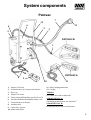
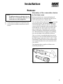
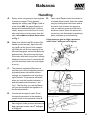
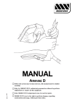
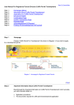
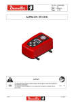
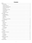
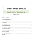
1
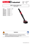
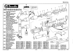
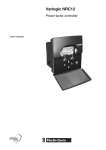
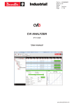
MANUAL
Patovac + Balsavac
Before the system may be taken into use, this manual must be studied
carefully.
Edition 1:1999
Only, by MEDICVENT, authorized personnel are allowed to perform
adjustments or repairs on this equipment.
Only MEDICVENT original parts may be used in repairs.
MEDICVENT reservs the right to perform changes, regarding
construction and usage, without previous notice.
Table of contents
Chapter
System components
Installation
Trouble shooting
Technical Data
Page
3.
4-5.
6.
7-8.
Safety
9.
Balsavac (Handling & Technical data)
10.
Handling
Safety
11.
12.
2
System components
Patovac
7
12
6
4
13
2
3
5
PATOVAC B
1
PATOVAC A
8
9
11
10
1.
2.
3.
4.
5.
6.
7.
8.
9.
10.
Adapter 19/22 mm
Evacuation hose (Ø 19 mm) made of hytrel
Hose cap
Adapter 38/19 mm
Totally enclosed Mains filter (sterile) LP-10-38
Fan unit with filterwell and built in safety valve
Evacuation hose (Ø 40 mm)
Auxiliary cable
Control box, stepless
Mains cable (Euro)
11. Safety isolating transformer
12. Carriage
Tillbehör:
13. Outlet valve with or without lid
150010 PATOVAC A:
Oscillating pneumatic bone saw, Desoutter®.
150110 PATOVAC B:
Rotating pneumatic bone saw, Desoutter®.
3
Installation
Patovac
Installation of stationary fan unit
1. Place the fan in a suitable location. Install the fan
unit standing on it´s rubber feet, or screw it to a
carriage to enable mobile use of the unit.
2. Connect the fan units outlet marked with an arrow pointing outwards to a suitable outlet
ventilation. Also connect the fan units left inlet
marked with an arrow pointing inwards to the
outlet valve in the application room. All these
connections are done through use of Extracflex
installation components (pipes, angles, muffs,
clips etc).
3. Connect the evacuation tube (Ø 40 mm) to the
central fan units outlet valve.
4. Connect the control box to the fan unit with the
auxiliary cable, through use of a 5-wired cable
(Area 5 x 0,22 mm) between fan and a properly placed female DIN contact in the
Controlbox
Auxiliarycable
5-wired
cable
Fanunit
This means that a safety isolating transformer
does not have to be used.
WARNING!
A system without a safety isolating
transformer does not comlpy with norm
IEC 601:1. Sensitive equipment might
be disturbed.
5. Connect the Mains cable from the transformer
and to a suitable powersupply.
6. Connect the control box to the fan unit with the
auxiliary cable.
Connection patient system
Stationary fan unit:
1. Attach the Mains filter (sterile) firmly through
use of for example a short tube (Ø 40 mm) with
muffs in both ends. These muffs are adapted to
be connected to the outlet valve in the appl.
room.
Mobile fan unit:
application room according to the picture above.
ATT: An alternative is to have the control layed
in into the wallpanel (app.box).
Installation of mobile fan unit
1. Place the fan in a suitable location. The fan unit is
mounted on a carriage to enable mobile use of
the unit.
2. Connect the evacuation tube (Ø 40 mm) to a
suitable evacuation device for the buildings
ventilation system.
3. Connect the other end of the evacuation tube to
the fan units outlet marked with an arrow pointing
outwards (the right outlet seen from behind).
1. Attach the Mains filter (sterile) firmly to the
hose which is located in the filterwell. The filter
is kept in place on the hose with a hose clip.
Insert the filter into the filterwell.
N.B!
A flow arrow is located on the filter which
enables correct installation of thefilter. The
arrow declares the flow direction the air must
have through the filter.
2. Connect the adapter to the filters other end.
3. Connect evacuation hose (Ø 19 mm) to the
adapter.
4. Connect the hose to the evacuation device.
5. Connect the evacuation device to the bone saw.
4. Connect the safety isolating transformer device
contact to the fan unit. An exception from norm
IEC 601:1 might be allowed for autopsy rooms.
4
Installation
Patovac
ATT:
If a different bonesaw already is in use,
Medicvent can normally adapt the evacuation device to this equipment.
6. Connect the Desoutter hoses to the bone saw.
7. Activate the fan with the control boxes on/offswitch.
Assembly of the evacuation device
to the bone saw:
Make sure that the saw is turned off and that all
supply connections are extracted from their power
source (Pneumatic hose or Mains cable).
The saw blade which is fitted to the rotating saw must
not exceed Ø 45 mm. This limitation relates to the
semicircular shape of the evac.-device. The shape
encases a little less than half of the saw blade which
means that the evac. device gets very close to the
place of application. This makes for an extremely
effective evacuation of all the debris caused by the
saw. This limitation does not apply to an oscillating
saw since the shape of the sawblade is different.
The evac.-device is assembled to the bone saw by
bringing it over the saw blade and then twisted on to
the white adapter on the saw (In acc. to Pic.1). The
fixed adapter is made of Pom Acetal and fitted with
an O-ring which makes for a safe connection of the
evac.-device.
The instructions above applies to all bone saws
modified by Medicvent.
Pic. 1.
5
Handling
Patovac
Directions of use
Clean and disinfect
• Change the Mains filter (sterile) independent on
activity 4–6 times/year. For hygienic reasons
the filter should be exchanged at least once every
three months.
In reference to cleaning and disinfecting the
Patovac systems components can be divided into
three groups:
• The Mains filter (sterile) is delivered with a lid that
is put on used filters to avoid exposing the surroudings to the contents of it.
• A holder for bone saw and control box can be
mounted on the fan units carriage.
Group 1
Decontaminator (80-85°C ) or autoclave (120°C):
Evacuation hose (Ø 19 mm)
Adapter
Evacuation device
Group 2
Washing in mild detergent (60–70° C):
Patovac has no components in this group
Group 3
Wipe off with disinfectant:
Bone saw (N.B! Not safe to flush)
Holder for bone saw and control box
Saw blades
Hose set Desoutter
Evacuation tube (Ø 40 mm)
Control box
Auxiliary cable
Mains cable
Fan unit
Carriage
Mains filter (sterile) external cleaning
N.B!
The Bonesaw should not be immersed in
water. If this has happened the saw should
be run for a while to evaporate the water
that might have entered the transmission.
N.B!
Detergent with a high pH-value might cause discolouration of aluminium. Some alcohol dissolvents might cause damages to
the control box.
6
Technical data
Patovac
Component
Material
Cleaning.grp.
Bone saw
Anodized aluminium
Group 3
Evacuation device
Stainless steel
Group 1
Evacuation hose (Ø 19 mm)
Hytrel
Group 1
Adapter
Pom Acetal
Group 1
Mains filter LP-10-38
Plastic
Group 3
Fan unit
Castings/aluminium
Group 3
Evacuation tube (Ø 40 mm)
PVC
Group 3
Auxiliary cable
PVC
Group 3
Control box
PVC
Group 3
Mains cable
PVC
Group 3
Outlet valve
PVC
Group 3
Carriage
Steel
Group 3
Holder for bone saw/control box
PVC and stainless steel
Group 3
Hose set Desoutter
PE-PUR
Group 3
Saw blade Desoutter
Steel/teflon
Group 3
7
Technical data
Fan unit Patovac
Voltage feed:
220 V, 50 Hz 1-phase ±10%
Current:
4 A (max)
Power requirements:
0,3 kVA (max)
Airflow:
45 m3/h (max)
Dimensions:
Height
Width
Depth
Weight:
18 kg
400 mm
400 mm
400 mm
8
Safety
Patovac
WARNING!
Constitutes a risk for injuries on
patient and user.
N.B!
Constitutes a risk for damages to
equipment. Only use components
that MEDICVENT has delivered
and/or approved.
ATT:
Attention, reference.
Safety Patovac
• Only by MEDICVENT authorized personnel
are allowed to perform adjustments or repairs
on this equipment.
• Only MEDICVENT original parts may be used
in repairs.
WARNING! Observe the palpable risks of cut
wounds that are always present when
using a bone saw. When using a
rotating blade this risk is very
prominent even if the Patovac evac.device functions as a protection so that
you can easily hold it in a normal
twohand grip without unvoluntarily slip
against the blade.
WARNING! A system without a safety isolating
transformer does not comply with
norm IEC 601:1. Sensitive equipment might be disturbed.
N.B!
Be careful when removing or
attaching the evac. device, for example
during cleaning. The blade might break
or be damaged so that vibrations arise
and might also give the saw a tendency
to “throw”, especially for rotating
blades.
N.B!
A flowarrow is located on the filter
which enables correct installation of
the filter. The arrow declares the flow
direction the air must have through
the filter.
N.B!
The Bonesaw should not be
immersed in water. If this has
happened the saw should be run for
a while to evaporate the water that
might have entered the
transmission.
N.B!
Detergent with a high pH-value might
cause discolouration of aluminium.
Some alcohol dissolvents might cause
damages to the control box.
ATT:
If a different bone saw already is in
use, Medicvent can normally adapt
the evacuation device to this equipment.
9
Balsavac
Handling/Technical data
Installation and directions of use
• The nozzle is connected to the evac. device.
• The same fan unit that is used in the Patovac
system is also used here in the Balsavac system.
• Accessories available:
A) Enclosing instrument to tighten between nozzle
and body connection.
B) Small mobile compressor.
• A fluid separator is attached to one side of the fan
unit. The fluid separator protects the fan from
attacks of formaldehyde.
N.B!
The Fluid separator must be drained daily
after use. Open the tap underneath the
container.
• To the fluid separator an evacuation hose is
connected and on the other side of the separator
another evacuation hose is connected which on
the other end is connected to the filter on the fan
unit.
Technical data and cleaning:
In ref. to cleaning there are 3 groups:
Group 1 = Decontaminator (80-85°C ) or autoclave
(120°C)
Group 2 = Washing in mild detergent (60–70°C)
Balsavac has no components in group 2
Group 3 = Wipe off with disinfectant
Fan unit
See Patovac
Group 3
Fluid separator
PVC
Group 3
Holder for
Fluid separator
PVC
Group 3
Evacuation tube
Ø 40 mm, PVC
Group 3
• The Balsavac consist of a stainless pressure vessel
on wheels, which is filled with embalming fluid.
Evacuation hose
Ø 19 mm, Hytrel
Group 1
Evacuation device
Transparent silicon
Group 1
• Embalming fluid is pumped up with compressed air
from a central pneumatic system or a mobile
compressor. The pressure is indicated on a
pressuremeter on the vessel.
Fluid gun
Nickel-plated brass Group 1
Pressure reduction
Brass
Group 3
Pressure vessel
Stainless steel
Group 3
Hose from
pressure vessel
PVC
Group 3
Enclosing instr.
Stainless steel
Group 1
220 V AC 50 Hz
1-phase
8kg/cm2
15 kg
Group 3
• On the evacuation hose with a free end an evac.
device is attached which together with the
evacuation system prevents the embalming fumes
from spreading in the application room.
• The pressure is regulated on a stepless adjustable
pressure reduction. This enables that during work
you can adjust the pressure to be in accordance
with the condition of the body.
• To the pressure reduction a hose is connected and
on the other end of the hose a fluid gun with a
nozzle is connected.
Compressor
Voltage feed:
Max pressure:
Weight:
10
Balsavac
Handling
A.
Empty all the overpressure that might be
in pressure vessel. This is done by
opening the refilling cap 3 Fig1 a little or
a few turns (NB! the gases flowing out
derives from embalming fluids. Consequently always use some form of evacuation and keep your face away from the
cap). All numbers in these texts refers
to Fig. 1.
B.
Make sure that the tap 2 is closed (The
handle across the tap). Open the refilling cap 3 use the funnel to fill embalming fluids (do not fill over marking 20 on
the meauring glass, cause this spoils the
performance). Screw the cap real tight.
If the hose with the fluid gun isn´t already
attached it is done now on connection 4
(pull the shell back when the hose nipple
is put in).
C.
The pressure regulation 5 works in a
way that you lock the adjusted pressure
by pushing down the handle and accordingly you release the lock by pulling
up the handle. The pressure increases
when you turn the handle clockwise (+)
and decreases anticlockwise (-) see
Fig.1. The first time you use the Balsavac you should adjust the regulation to
the lowest pressure.
D.
Connect an airsupply to valve 1 and
increase the pressure in the pressure
vessel check on the pressure meter 6.
N.B!
Max 6 kg/cm3. If the pressure becomes too
high a pressure release valve 7 will open
at 12 kg/cm3.
E.
Open valve 2 and connect the nozzle to
a suitable blood vessel. Start the embalming by holding down the button and at
the same time increase the pressure
until you obtain a pressure sufficient to
the blood vessel. When the pressure is
correct you lock the handle by pushing it
down, and then go on embalming.
If the pressure gets to high a pressure
relief valve 7 will open at 12 kg/cm3.
Fluid separator
Pressure vessel for
embalming fluid
Evacuation device
Fluid gun
11
Safety
Balsavac
WARNING!
Constitutes a risk for injuries on
patient and user.
N.B!
Constitutes a risk for damages to
equipment. Only use components
that MEDICVENT has delivered
and/or approved.
ATT:
Attention, reference.
Safety Balsavac
• Only by MEDICVENT authorized personnel
are allowed to perform adjustments or repairs
on this equipment.
• Only MEDICVENT original parts may be used
in repairs.
WARNING! A system without a safety isolating
transformer does not comply with
norm IEC 601:1. Sensitive equipment
might be disturbed.
N.B!
The Fluid separator must be drained
daily after use. Open the tap
underneath the container.
N.B!
Max 6 kg/cm3. If the pressure
becomes too high a pressure release
valve will open at 12 kg/cm3.
12