1
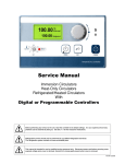
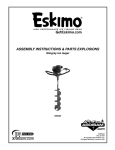
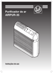
Retro Plenum Heater Easy, low cost retrofit of gas to electric dual-fuel heat • 34,000 btu heating capacity • Uses low electric heat rate for majority of heating season • Can be added to most existing 100 amp services • Low (400 cfm) minimum airflow requirement • Easy installation for various sized plenums Unique features include: • Designed for both single and variable speed blowers • Current Sensor or utility load control compatible • Automatically switches to fossil fuel back-up when electric cannot satisfy heat call due to ambient temperature conditions Current Sensor included at Thermost Easy and cost effective way to add electric heat to fossil fuel furnaces with or without A/C. Can be safely installed with most 100 amp service entrances* thanks to a Current Sensor which monitors the use of a large electrical appliance such as a water heater or dryer. If the appliance is in use the plenum heater is automatically put into standby mode and will wait as long as the appliance is in use. If heat is required and the plenum heater is in standby or if it cannot satisfy the heating demand, it will automatically switch to the fossil fuel furnace for auxiliary heat. To simplify installation, the Current Sensor may be mounted in the electrical panel.* T-10 U-DFCT * Check with local codes before installing. Electric Plenum Heater Standard Staged Model: Application is fossil fuel furnace, dual fuel, with or without A/C system Modulating Model: Application is fossil fuel furnace, dual fuel, with heat pump or multiple zones. Unit includes solid state relays, plenum temperature sensor and adjustable setting on board to control plenum supply air temperature. Retro Model: Application is fossil fuel furnace, dual fuel, with or without A/C system and 100 amp electrical service. Unit includes current sensing relay that controls electric heat when next largest electric appliance comes on. The retro is only available in 10kW. All models include the following features: 1. Available from 5 - 30 kW: Covers variety of heating requirements, custom units available 2. High grade nickel-chrome open-coil elements: 40 cfm per KW minimum airflow requirement, longer element life and no buzzers 3. All units include Center Coil and baffles for larger plenums that attach to heater frame: Easy installation over A-coil as well as side baffling during installation 4. Standard in up flow, down flow - Horizontal configuration available: Units available for all types of installations 5. Automatic and manual-reset cut-outs: protects against overheating 6. Circuit breakers: provides safe isolation of elements 7. Built-in dual fuel control: allows unit to be set in dual fuel or fossil fuel mode, accepts "load shedding" signal from utility company and switches to fossil fuel back-up automatically 8. Isolation relays: AC ready, no need for adding relays 9. One size frame for 5 - 20 kW: Fits both 15" and 18" plenums, reduces inventory 10. One size frame for 25 & 30 kW: 19" frame for both sizes, fits larger plenums 11. 240/1 standard, three phase and custom sizes available Contact your Thermolec Sales Representative for Custom Unit Quotes 3412BTU/kWh CostPerMillionBtu 1.00 13.33 12.50 12.20 11.76 11.11 10.87 10.53 1.05 14.00 13.13 12.80 12.35 11.67 11.41 11.05 1.10 15.36 14.40 14.05 13.55 12.80 12.52 12.12 1.20 16.75 15.71 15.32 14.78 13.96 13.66 13.23 1.30 18.15 17.02 16.60 16.01 15.13 14.80 14.33 3.20 30.72 28.80 28.10 27.10 25.60 25.04 24.25 3.30 31.68 29.70 28.97 27.95 26.40 25.82 25.01 3.35 32.16 30.15 29.41 28.37 26.80 26.22 25.39 3.40 32.64 30.60 29.85 28.80 27.20 26.61 25.77 1.40 19.55 18.32 17.88 17.25 16.29 15.93 15.43 1.10 14.67 13.75 13.41 12.94 12.22 11.96 11.58 3.45 33.12 31.05 30.29 29.22 27.60 27.00 26.15 1.50 20.94 19.63 19.15 18.48 17.45 17.07 16.53 1.15 15.33 14.38 14.02 13.53 12.78 12.50 12.11 3.50 33.60 31.50 30.73 29.64 28.00 27.39 26.52 1.60 22.34 20.94 20.43 19.71 18.62 18.21 17.64 1.20 16.00 15.00 14.63 14.12 13.33 13.04 12.63 3.55 34.08 31.95 31.17 30.07 28.40 27.78 26.90 1.70 23.73 22.25 21.71 20.94 19.78 19.35 18.74 1.25 16.67 15.63 15.24 14.71 13.89 13.59 13.16 3.60 34.56 32.40 31.61 30.49 28.80 28.17 27.28 1.80 25.13 23.56 22.99 22.17 20.94 20.49 19.84 1.30 17.33 16.25 15.85 15.29 14.44 14.13 13.68 3.65 35.04 32.85 32.05 30.92 29.20 28.56 27.66 1.90 26.53 24.87 24.26 23.41 22.11 21.63 20.94 1.35 18.00 16.88 16.46 15.88 15.00 14.67 14.21 3.70 35.52 33.30 32.49 31.34 29.60 28.95 28.04 2.00 27.92 26.18 25.54 24.64 23.27 22.76 22.04 1.40 18.67 17.50 17.07 16.47 15.56 15.22 14.74 3.80 36.48 34.20 33.36 32.19 30.40 29.74 28.80 2.10 29.32 27.49 26.82 25.87 24.43 23.90 23.15 1.45 19.33 18.13 17.68 17.06 16.11 15.76 15.26 3.90 37.44 35.10 34.24 33.03 31.20 30.52 29.56 2.20 30.72 28.80 28.09 27.10 25.60 25.04 24.25 1.50 20.00 18.75 18.29 17.65 16.67 16.30 15.79 4.00 38.40 36.00 35.12 33.88 32.00 31.30 30.31 2.30 32.11 30.10 29.37 28.33 26.76 26.18 25.35 1.55 20.67 19.38 18.90 18.24 17.22 16.85 16.32 4.10 39.36 36.90 36.00 34.73 32.80 32.08 31.07 2.40 33.51 31.41 30.65 29.57 27.92 27.32 26.45 1.60 21.33 20.00 19.51 18.82 17.78 17.39 16.84 4.20 40.32 37.80 36.88 35.57 33.60 32.87 31.83 2.50 34.90 32.72 31.92 30.80 29.09 28.45 27.56 1.65 22.00 20.63 20.12 19.41 18.33 17.93 17.37 4.30 41.28 38.70 37.75 36.42 34.40 33.65 32.59 2.60 36.30 34.03 33.20 32.03 30.25 29.59 28.66 1.70 22.67 21.25 20.73 20.00 18.89 18.48 17.89 4.40 42.24 39.60 38.63 37.27 35.20 34.43 33.34 2.70 37.70 35.34 34.48 33.26 31.41 30.73 29.76 1.75 23.33 21.88 21.34 20.59 19.44 19.02 18.42 4.50 43.20 40.50 39.51 38.11 36.00 35.21 34.10 2.80 39.09 36.65 35.76 34.49 32.58 31.87 30.86 1.80 24.00 22.50 21.95 21.18 20.00 19.57 18.95 4.60 44.16 41.40 40.39 38.96 36.80 36.00 34.86 2.90 40.49 37.96 37.03 35.73 33.74 33.01 31.96 1.85 24.67 23.13 22.56 21.76 20.56 20.11 19.47 0.076 22.27 14.85 11.14 8.91 8.10 7.42 6.85 6.36 5.57 4.70 45.12 42.30 41.26 39.81 37.60 36.78 35.62 2.95 41.19 38.61 37.67 36.34 34.32 33.58 32.52 1.90 25.33 23.75 23.17 22.35 21.11 20.65 20.00 0.078 22.86 15.24 11.43 9.14 8.31 7.62 7.03 6.53 5.72 AnnualFuelUtilitizationEfficiency(AFUE)Themeasureofannualefficiencyofaresidentialheatingfurnaceorboiler.Accountsforoperationenergylossesoftheheatingunit CoefficientofPerformance(C.O.P.)Thesameastheefficiencystatedasaratioofworkorusefulenergyoutputofasystemvs.theamountofenergyinputtedintothesystem. EnergyFactor(EF)Theefficiencyormeasureofoverallefficiencyofavarietyofappliances.WaterheaterefficienciesareratedbyEF. 3.25 31.20 29.25 28.53 27.53 26.00 25.43 24.63 138,900BTU/galllon 1.00 13.96 13.09 12.77 12.32 11.63 11.38 11.02 95,500BTU/gallon 0.95 12.67 11.88 11.59 11.18 10.56 10.33 10.00 100,000BTU/therm 0.90 12.00 11.25 10.98 10.59 10.00 9.78 9.47 EnergyEfficiencyTerms 75% 80% 82% 85% 90% 92% 95% $/gal FuelOil 75% 80% 82% 85% 90% 92% 95% $/gal Propane 75% 80% 82% 85% 90% 92% 95% $/ccf NaturalGas $/kWh 0.038 0.040 0.042 0.044 0.046 0.048 0.050 0.052 0.054 0.056 0.058 0.060 0.062 0.064 0.066 0.068 0.070 0.072 0.074 100% 11.14 11.72 12.31 12.90 13.48 14.07 14.65 15.24 15.83 16.41 17.00 17.58 18.17 18.76 19.34 19.93 20.52 21.10 21.69 150% 7.42 7.82 8.21 8.60 8.99 9.38 9.77 10.16 10.55 10.94 11.33 11.72 12.11 12.50 12.90 13.29 13.68 14.07 14.46 200% 5.57 5.86 6.15 6.45 6.74 7.03 7.33 7.62 7.91 8.21 8.50 8.79 9.09 9.38 9.67 9.96 10.26 10.55 10.84 250% 4.45 4.69 4.92 5.16 5.39 5.63 5.86 6.10 6.33 6.57 6.80 7.03 7.27 7.50 7.74 7.97 8.21 8.44 8.68 275% 4.05 4.26 4.48 4.69 4.90 5.12 5.33 5.54 5.76 5.97 6.18 6.39 6.61 6.82 7.03 7.25 7.46 7.67 7.89 300% 3.71 3.91 4.10 4.30 4.49 4.69 4.88 5.08 5.28 5.47 5.67 5.86 6.06 6.25 6.45 6.64 6.84 7.03 7.23 325% 3.43 3.61 3.79 3.97 4.15 4.33 4.51 4.69 4.87 5.05 5.23 5.41 5.59 5.77 5.95 6.13 6.31 6.49 6.67 350% 3.18 3.35 3.52 3.68 3.85 4.02 4.19 4.35 4.52 4.69 4.86 5.02 5.19 5.36 5.53 5.69 5.86 6.03 6.20 400% 2.78 2.93 3.08 3.22 3.37 3.52 3.66 3.81 3.96 4.10 4.25 4.40 4.54 4.69 4.84 4.98 5.13 5.28 5.42 Electricity SystemEfficiency (C.O.P.orEF) SystemEffciency SystemEffciency SystemEffciency 4.80 46.08 43.20 42.14 40.66 38.40 37.56 36.38 3.00 41.88 39.27 38.31 36.96 34.90 34.15 33.07 1.95 26.00 24.38 23.78 22.94 21.67 21.20 20.53 0.080 23.45 15.63 11.72 9.38 8.53 7.82 7.21 6.70 5.86 5.00 48.00 45.00 43.90 42.35 40.00 39.13 37.89 3.10 43.28 40.58 39.59 38.19 36.07 35.28 34.17 2.05 27.33 25.63 25.00 24.12 22.78 22.28 21.58 0.100 29.31 19.54 14.65 11.72 10.66 9.77 9.02 8.37 7.33 5/18/2008 4.90 47.04 44.10 43.02 41.50 39.20 38.34 37.13 3.05 42.58 39.92 38.95 37.57 35.49 34.71 33.62 2.00 26.67 25.00 24.39 23.53 22.22 21.74 21.05 0.090 26.38 17.58 13.19 10.55 9.59 8.79 8.12 7.54 6.59 THERMOLEC Installation instructions for Plenum-mounted add-on electric heaters MODEL TU AUGUST 2004 VERSION 6 THERMOLEC PLENUM HEATER MODEL TU BEFORE YOU START - GENERAL SAFETY AND INSTALLATION PRECAUTIONS Please read and understand these instructions fully before you begin this installation and save them for future reference. The manufacturer will assume no responsibility and the warranty will be void if the user does not adhere to the following precautions. 1 - LIMITED WARRANTY 1.1 THERMOLEC LTD., warrants the elements of its plenum heaters against all defects in material and workmanship for ten (10) years, and all other components for two (2) years after date of shipment from its factory. 1.2 THERMOLEC LTD., will repair or replace, in their factory or on site, at their sole discretion, the plenum or any part thereof, which, in their opinion, is defective. Any misuse of this heater or any repair done by people other than authorized Thermolec personnel, without Thermolec's written consent, will void this warranty. 1.3 THERMOLEC LTD., will not be held responsible for any accidental or consequential damage or delay, nor will Thermolec be held responsible for damages caused by the replacement of the plenum heater. This limited warranty is granted by Thermolec LTD., 2060 Lucien-Thimens Street, Montreal, Canada, H4R 1L1. 2 - INSTALLATION PRECAUTIONS AND SAFETY WARNINGS 2.1 This unit is designed to be used only in a up-flow or down-flow installations and it should be installed only on oil or gas furnaces. (No wood or solid fuel). For other applications, please contact the factory. Custom units are available for horizontal installations. 2.2 This unit is not designed to be installed side by side. 2.3 This unit must be installed by a qualified installer and Thermolec will not be held responsible for the quality of the installation. 2.4 Always check that you are not about to cut or drill into any air conditioning or electrical accessory during installation. 2.5 The installation and wiring must comply with national and local electrical, plumbing and building codes. 2.6 Electrical wiring must not come into contact with sharp edges or hot surfaces. 2.7 Please use common sense and normal safety precautions during the installation. 2.8 Please beware of sharp edges when you cut into a metal duct. 2.9 Always shut the power off before working on such installation. An electric shock could cause serious injury. Page 1 3 - DISCLAIMER This warranty only applies if the unit is properly installed and operated according to the manufacturer's instructions provided with this product. This limited warranty does not cover normal maintenance : - replacement of fuses or breakers, filters, refrigerant, etc., - transportation and installation charges for the replacement part or component, - any other service call or repair labor. Replacement of a part or component under this limited warranty does not extend the warranty term or period. This limited warranty does not apply to any part or component that is damaged in transit or handling; has been subject to abuse, neglect or accident; has not been installed, operated and serviced according to Thermolec's instruction booklet; has been operated beyond factory rated capacity; altered in any such way that its performance is affected. There is no warranty due to neglect, alteration, or ordinary wear and tear. Thermolec's liability is limited to replacement of defective parts or components and does not include payment of the cost of shipping charges and/or labor charges to remove or replace such defective components or parts. Some states do not allow the exclusion or limitation of incidental or consequential damages, so the limitation of exclusion in the warranty may not apply to you. We do not warranty this product suitable for the specific installation or application. It is the owner's (or installer's) responsibility for proper application. There are no other express warranties. Specification sheets and descriptions of this product are only to identify it, and are not a warranty claim that the unit fits the description. Thermolec is not bound by representatives, installers, warranties, or promises made by others beyond the terms of this express warranty. In no event shall Thermolec be responsible for any installation incidental or consequential damages. Thermolec reserves the right to make changes in the design and material of its products without incurring any obligation to incorporate such changes in the units completed on the effective date of such changes. Page 2 THESE INSTALLATION INSTRUCTIONS COVER: MODEL TU T-5 U to T-30 U T-5 U-DFC to T-30 U-DFC (5 Kw to 30 Kw) GENERAL NOTES - The installation of this unit should be in accordance with the regulations of the authorities having jurisdiction. CAUTIONS 1. Before installation, ensure that the local electrical inspection authority will accept connection of this equipment to the existing panel. 2. This equipment may only be installed and tested by qualified personnel. 3. The electrical power supply should be checked for adequacy for the proposed additional load. 4. Ensure that the heat output capacity of the installed electrical Add-on Heaters does not exceed the rated output capacity of the furnace burner. 5. This heater is for use with an in-line (hi-boy) or up-flow (lo-boy) oil or gas fired furnace. OPERATING INSTRUCTIONS The controls provided with this unit prevent simultaneous operation of the add-on heater and the fossil fuel burner. In the case of malfunction, shut down the equipment and call a qualified electrician. Page 3 FIELD TESTS: A. Before Installation of the Add-on Heater: 1. Ensure that the burner does not cycle due to repeated operation of the furnace’s high limit control. 2. Determine whether stabilized outlet air temperature during burner operation is below 150°F (66°C) in the main outlet duct. If it does exceed 150°F (66°C) make the following adjustments to the Ventilation System in progressive steps: Note: In most cases, only steps a) & b) will be necessary. MOTOR MOTOR PULLEY BELT FAN PULLEY FAN BLADES a) Check if filters are clogged; b) Check if fan blades are clean. If not, remove the blower from its compartment and clean with a brush; c) Adjust the motor pulley to increase its diameter; d) Change the fan pulley for a smaller size; e) Change the motor pulley for a larger size; f) Change the motor and make sure that the fan control and wiring are adequate. Note: If steps c), d) & e) are necessary, make sure that the existing motor is adequate: The current drawn must not exceed the nameplate specifications. Important: The blower must not be changed. If the system cannot provide sufficient airflow after changing the motor, do not install the add-on heater in that furnace. B. After Installation of the Add-on Heater: 1. Ensure that the burner does not cycle due to repeating operation of the furnace’s high limit control. 2. Ensure that stabilized outlet air temperature during burner operation does not exceed 160°F (72°C) in the main outlet duct. 3. Run burner to ensure that the blower starts soon enough to prevent the manually resettable temperature limiting control on the Add-on Heater from tripping. 4. Operate the Add-on Heater to ensure satisfactory operation without overheating. Note: Where a cooling coil is present, additional checks should be made to ensure adequate airflow exists for cooling system operation. Page 4 MECHANICAL SECTION A. Product Inspection 1) Inspect the carton and heater and report any damage at once. NEVER INSTALL A DAMAGED HEATER 2) Content of carton: One plenum heater and baffles. Modulating models include a plenum temperature sensor. 3) File claim with shipping company if shipment is damaged. B. Installation Instructions: «Cautions» - The installation, location, position and orientation of the add-on heater must conform with the following: 1) This heater must be installed downstream of the furnace in the warm air plenum. 2) This heater must be installed downstream of the furnace safety limit control. 3) No deformation, removal or displacement of any part of the furnace is permitted. 4) The position of the add-on heater must be as indicated on the front of the heater control box (Please see Fig. 1). 5) The heater axis must be in line with the plenum axis. 6) Do not install heater from top or bottom of duct. (Please see Fig. 2). 7) Always check that you are not about to cut or drill into any air conditioning or electrical accesory during installation. SUPPLY PLENUM DUCT WRONG FURNACE FURNACE FIG. 1 STANDARD INSTALLATION CLEARANCE FIG. 2 The heater must be installed in the warm air plenum. A minimum distance of 14 inches is required from the furnace to the elbow, Tee or plenum end take-off of the main supply duct (Please see Fig. 3). SUPPLY DUCT SUPPLY DUCT 2" min. 6" min. 14" min. 14" min. 6" min. FURNACE FIG.3 Page 5 FURNACE If a cooling coil is installed in the warm air plenum a minimum distance of 1” or 7” is required between the top of the cooling coil and the add-on heater (depending from which side of the plenum the add-on heater is inserted). (Please see Fig. 4) In both cases, a minimum distance of 2” must be kept between the top of the add-on heater and the elbow, Tee or plenum-end take off of the main supply duct. FIG. 4 MAIN SUPPLY DUCT 7" COOLING COIL 1" FURNACE SUPPLY PLENUM 28" min. FIG. 5 10" min. FURNACE FLUE PIPE WALL OR OBSTRUCTION SERVICE CLEARANCE AND CLEARANCE FROM FLUE PIPE The heater may be installed on any available side of the plenum. An installation and service clearance of 28 inches is required from the heater control box to a wall, partition or any other obstruction. If the heater is installed on the same side as the flue pipe a minimum clearance of 10 inches must be maintained between the flue pipe and the heater control box. (Please see Fig. 5) Select the plenum side, which offers the most space for installation and service. VERY IMPORTANT BAFFLES MUST ASSURE MAXIMUM AIR FLOW OVER THE HEATING ELEMENTS. - Screw the baffles to bottom flanges of casing, as shown in Fig. 6. - Cut baffles to size allowing only 1/8” clearance for insertion of heater. WIDTH OF SUPPLY PLENUM BAFFLE HEATER ELEMENT CASING FIG. 7 PLENUM FIG. 6 HEATER CONTROL BOX TOP VIEW OF PLENUM SHOWING INSTALLED HEATER AND BAFFLES. AIR FLOW All the air from the furnace must pass through the heater element. If the heater element casing is smaller than the plenum the space between the plenum and the element casing must be blocked off with baffles. (Please see Fig. 7) Page 6 HEATER UP FLOW MOUNTING Cut out heater opening at a minimum distance of 6 inches from the furnace. Center the opening on the plenum. Provide slots for insertion if baffles are installed. (Please see Fig. 8). Note: The 6 inch dimension from the top of the furnace to the heater opening in the plenum may be increased. If increased, 14 inch minimum dimensions in Fig. 3 must be increased accordingly. Slip the heater element into the opening. Make sure that the opening and slots are entirely covered by the heater mounting flanges. Secure the heater to the plenum by means of metal screws through the pre-drilled holes. DOWN FLOW MOUNTING HUMIDIFIER DO NOT USE PAN & PLATE TYPE HUMIDIFIERS WITH THE WATER RESERVOIR INSIDE THE WARM AIR SUPPLY PLENUM. Only «Pressure Differential» type humidifiers (preferably a power humidifier) should be used. If the round inlet duct of the humidifier is connected on the hot side of the heater, it is strongly recommended to insert a reducing ring between the round inlet duct of the humidifier and the opening in the plenum such that the effective opening for the humidifier will approximate 4” in diameter. This will reduce the volume of short-circuited air through the humidifier connection (Please see Fig. 9). Page 7 HORIZONTAL MOUNTING ELECTRICAL SECTION Common to TU and TU-DFC models 1- Disconnect all power sources before opening electrical boxes and working within. 2- Read the nameplate and markings carefully and consult the wiring diagram before you start wiring. 3- Wires and protective equipment should be sized according to the National Electrical Code requirements. 4- Use only wires suitable for at least 75°C. Consult the table “Characteristics” to find the number of feeders required. 5- Connect Thermostat wires to terminals on heater as shown on wiring diagram. 6- Anticipation. Set the room thermostat heat anticipator at 0.2. Perform start-up and required field tests. Please see Fig. 10 for schematic wiring. (DFC model is shown). 7- Wire heater to furnace as shown on the wiring diagram. For two stage control and standard plenum heater, remove jumper from terminals 1 and 2 on heater and wire with isolation relay to W2 (second stage) on furnace. ELECTRICAL SECTION Specific to model TU-DFC 8- Connect load management control to terminals OP and R on heater. START-UP for Model TU (mono-energy) 1234- Do required fields tests after installation of the Add-on Heater as detailed on page 4. Set the thermostat above the room temperature. Stages will sequence ON at 5 seconds interval. Measure the amperage drawn by the heater and compare it with the one shown on the nameplate. When the thermostat is satisfied, the stages will sequence OFF at 5 seconds interval. 5- Make sure the fan is ON when the heater is energized. 6- Set the room thermostat to the desired set point. 7- Your heater is now ready and functional. SEQUENCE OF OPERATION for Model TU-DFC (dual-energy) 1- The heater is provided with a two-position mode selector switch. In the “gas / oil” mode the room thermostat will call upon the furnace to maintain the house temperature at the level desired by the user. The “Dual-Energy” mode gives automatic control to the outdoor thermostat or other switching signal for dual-energy control. When the contacts are closed, the electric mode is selected. When the contacts are open, the “gas / oil” mode is selected. A green pilot light indicates the mode in operation. 2- An electronic fault sensor will automatically transfer from one mode to the other in case of failure of one system. A mode is considered to have failed when it is unable to satisfy the room thermostat for more than 2 hours. Page 8 START-UP for Model TU-DFC (Dual-energy) 1- Do required fields tests after installation of the Add-on Heater as detailed on page 4. 2- The heater is supplied with a built-in 2 position mode selector switch. ( ) position - Heating by means of original furnace. ( ) position - Dual-energy mode. 3- Simulate a heating demand by setting the room thermostat above the room temperature. 4- Switch the mode selector to position ( ) and check if the burner responds to thermostat demand. 5- Switch the mode selector to the dual-energy position ( ). If you jump terminals OP and R the electric mode is selected. The fan will start and the heating elements will come on in sequence at 5 seconds interval. Measure the amperage drawn by the heater and compare it with the one shown on the nameplate. If you disconnect the load management control wires the “gas / oil” mode should be selected. 6- Switch the mode selector to the desired position and set the room thermostat to the desired set point. 7- Your heater is now ready and functional. Models Staged Dual-energy T-5 U-DFC T-10 U-DFC T-15 U-DFC T-18 U-DFC T-20 U-DFC T-25 U-DFC T-30 U-DFC Modulating Dual-energy T-10 U-DFC-MOD T-15 U-DFC-MOD T-18 U-DFC-MOD T-20 U-DFC-MOD T-25 U-DFC-MOD T-30 U-DFC-MOD kW @ 240V 5 10 15 18 20 25 30 10 15 18 20 25 30 Heating Sequences 1 2 3 4 4 4 4 2 3 4 4 5 5 Page 9 Current (Amps) Plenum Heater Breaker 20.8 30 41.6 60 62.5 2 x 40 75.0 2 x 50 83.3 2 x 60 104.0 3 x 50 124.0 3 x 60 41.6 62.5 75.0 83.3 104.17 125.0 1 2 2 2 2 60 x 60 1 x 30 x 50 x 60 x 60 1 x 30 x 60 1 x 40 Modulating Plenum Heater Instructions Installation 1. Prior to installation, perform field tests as detained on page 4 of this manual. 2. Install modulating plenum heater in plenum per instructions on pages 5 – 7 of this manual. 3. The DS-600 plenum temperature sensor is installed from 6" to 12" downstream of the plenum heater as show below. Wiring 1. Wire unit per instructions on page 8 of this manual. 2. If installing plenum heater with a heat pump system, use a heat pump thermostat and adjustable outdoor temperature sensor/thermostat. 3. If installing plenum heater with a standard heating/cooling system, use a standard heating/cooling thermostat." 4. Wire plenum heater to thermostat and heating/cooling equipment per attached wiring diagram. 5. Wire DS-600 plenum temperature sensor to terminals labelled “WT” on plenum heater PC board. 6. Set desired plenum discharge temperature using adjustable dial on plenum heater PC board. Use reference chart below for set point. DS-600 Duct Sensor Plenum Heater Heat Pump coil Furnace TH 600 TE MP E R ATUR E DIAL SE T P OINT TH 600 Temperature Set Point Co Fo #1 #2 #3 #4 #5 #6 #7 43.3 45 47.7 53.4 56.7 62.8 68.3 110 113 118 128 134 145 155 Page 10 Modulating Plenum Heater Instructions Sequence of operation, modulating plenum heater with heat pump 1. When the utility load management control is closed and outdoor temperature is above the set point of the outdoor thermostat, heat pump / electric heat is selected as first stage. With a call for heat, the heat pump will start and provide heat. If the DS-600 temperature sensor senses plenum temperature below the set point of the dial on the plenum heater control board, the plenum heater elements will energize, supplementing the heat provided by the heat pump and modulate to maintain the desired plenum temperature. If the utility load management control is opened, the fossil fuel back up will be selected. 2. When the utility load management control is closed and outdoor temperature is below the set point of the outdoor thermostat, the heat pump will be locked out. With a call for heat, the plenum heater will provide the full heat load and modulate the elements to maintain the desired plenum temperature. If the utility load management control is opened, the fossil fuel back up will be selected. 3. When the heat pump switches to defrost, the fossil fuel back up will be selected and the plenum heater will be locked out. After defrost, the system will switch back to heat pump / electric heat mode. 4. When the utility load management control is open, with a call for heat, the fossil fuel back up will be selected. 5. To manually select fossil fuel mode, switch heat pump thermostat to emergency. Sequence of operation, modulating plenum heater with standard heating/cooling system 1. When the utility load management control is closed, with a call for heat, the plenum heater will provide the full heat load and modulate the elements to maintain the desired plenum temperature. If the utility load management control is opened, the fossil fuel back up will be selected. 2. When the utility load management control is open, with a call for heat, the fossil fuel back up will be selected. Page 11 Modulating Plenum Heater Trouble Shooting Guide 1. Before you start; Identify your system, make sure that you are using the appropriate wiring diagram that matches the system components: A. Furnace (Single Stage or Two Stage, Variable Speed or Standard Drive) B. Cooling (Heat Pump or A/C, 1 stage or 2 stage) C. Thermostat (With or Without outdoor sensor?) 2. If Heat Pump; does O/B energize in heating or cooling mode? Jumpers on the Relay Board are in the normally closed position, Jumpers must be put to the normally open position if you energize O/B for heating. Same at your Thermostat. Step Issue 1 No Heat 2 No Heat What to Check Possible Cause/Problem On Relay Board Terminal Strip Check for 24 VAC to: OP,Y,R Off Peak Relay, Thermostat, Wiring and/or Transformer If No 24 VAC (See Possible Causes) If Yes: Continue to step 2 at Furnace On the TH600 Control Board: Check for continuity between C and W1, S1 and S2. If None (See Possible Causes) If Yes Continue to step 3 Bad Relay Board. O/B not correct as in "Before you Start" section. Double check main power to Plenum Heater transformer. Check Hi Limits manual and auto (Ohm or 24VAC). Reset Manual Limits (listen for click). Make man al and a to (Ohm or 24VAC) Reset Man al Limits (listen for click) Make TTripped Breaker, Bad High Limits; Auto/Manual, Bad i d B k B d Hi h Li it A t /M l B d sure back up contactor is pulled in. Check transformer fuse. Contactor, Blown Fuse If Yes (Continue to step 4) If Not (see possible causes) 3 No Heat 4 No Heat 5 Insuffcient Heat Turn Dial on TH‐600 board higher, check for green led lights on TH‐600 board. Heat Pump is putting out enough bTu's to satisfy heat If no lights; see possible causes. If yes; continue load on its own. 6 Insuffcient Heat Did you use the proper diagram (variable speed?), Is kW Perform an amp draw; If amperage is correct in refrence to name plate on unit; load properly sized, Dial on the TH‐600 board not in the see possible causes. If not; continue correct setting for discharge temp. needed 7 Insuffcient Heat Check for 24 Volts DC to SSR relays If no: see possible causes If yes; continue 8 Insuffcient Heat Check the high voltage side of SSR relay contacts (Should be 0 VAC) If not; see possible causes Remove wires from duct temperature sensor at the TH‐600 board. Does unit start? If yes; see possible causes (A). If no; see possible causes (B) (A): Bad duct temperature sensor (B) Faulty TH‐600 Board TH‐600 Board not functioning properly SSR Relay is faulty, Broken/Bad element (Ohm out to make sure) Step Issue 1 NoHeatNoFan 2 NoHeatNoFan 3 NoHeatNoFan 4 NoHeatBlowerison 5 NoElectricHeator NoA/C 6 InsuffcientHeat 7 InsuffcientHeat 8 InsuffcientHeat 9 InsuffcientHeat WhattoCheck PossibleCause/Problem OnRelayBoardTerminalStripCheckfor24VACto:OP,R,WT FurnaceTransformer,WiringtoThermostat,OffPeak IfNot(SeePossibleCause) Relay IfYes:Continuetostep2 OntheTH400Board: CheckforcontinuitybetweenCandW1,S1andS2 BadRelayBoard IfNot(SeePossibleCauses) IfYesContinuetostep3 Checkfor24VACatPlenumHeaterTransformerandFuse (A):CheckforVoltageatBreakers,Transformer IfNo:SeeCause(A) (B):TH400BoardFaulty IfYes:SeeCause(B) CheckforContinuityon Airflowissues,LowCFM,notwiredforvariable AutoHighLimits,ManualHighLimitsand speedblower,bafflesnotinstalledcorrectly,faulty BackUpContactor backupcontactororbadhighlimits. WiredImproperly,BadOffPeakRelay, Checkfor24VAC BadLoadControlboxathouseorUtilityiscurrently atOPterminalonRelayBoard inacontrolperiod. CheckAmpdraw: IfDrawingfullamps:heaterisoperatingatdesignspec(C). (C):AirfloworUnitisUndersized Ifnot:Continuetostep7 Checkfor24VDCtoOperatingContactorC1C4 IfNo:Seecause(D) (D):FaultyTH400Board IfYes:Continuetostep8 AretheOperatingContactor(s)closing? (E)BadOperatingContactor IfNot:Cause(E) IfYes:Continuetostep9 OhmoutElementsandCheckElementAmpDraws Iffullopen:Cause(F) (F)BadElement IfAmpDrawisincorrect:Cause(F) VISION PRO 8000 SET UP FOR USE WITH THE OUTDOOR SENSOR SYSTEM TYPE. SELECT # 170………OPTION # 7 (2H/1C WITH AUX HEAT) CHANGE OVER VALVE # 190……….OPTION # 0 REMOTE SENSOR # 340……….OPTION # 2 HEAT PUMP LOCKOUT # 350………. THIS IS AN INSTALLER TEMP OPTION AUX LOCKOUT # 360…………THIS IS AN INSTALLER TEMP OPTION * SEE BACK OF MANUAL FOR EXPLANATION OF LOCK OUT SETTINGS * VISION PRO 8000 SET UP FOR USE WITH NO OUTDOOR SENSOR SYSTEM TYPE. SELECT # 170………OPTION # 7 (2H/1C WITH AUX HEAT) CHANGE OVER VALVE # 190……….OPTION # 0 REMOTE SENSOR # 340……….OPTION # 0 **************** NOTE: ACTUAL #’s MAY CHANGE WITH MODEL OF STAT. It is essential to know your stat, as well as when and why it transfers voltage. Note: Use separate outdoor thermostat to lock out compressor (heat pump) based on outdoor temperature and heat with plenum heater only. Sequence of Operations: 1. 2. If outdoor temperature is above balance point programmed into the thermostat, Y1 will be energized and compressor (HP) will run. If outdoor temperature is below the balance point the thermostat will de‐energize Y1 and energize Auxiliary 1; allowing the compressor (HP) to run and also the plenum heater to run and supplement compressor (HP) as needed. 3. If outdoor temperature is below the balance point and also below compressor lockout temperature set at the outdoor thermostat then only the plenum heater will run. 4. If electric heat does not satisfy thermostat; Auxiliary 2 will be energized; this will shut off compressor and plenum heater, only allowing fossil fuel heat to run. Note: For 2 stage compressors (HP); connect Y2 from thermostat to Y2 at compressor (HP) and Y2 at furnace if terminal is applicable. Represented By: EP Sales, Inc. 7878 12th Ave. South Bloomington, MN 55425 [email protected] 952‐854‐4400 Tech Support 952‐854‐4441 Fax Honeywell Vision Pro IAQ with Outdoor Sensor: Setup guide and sequence of operations for Thermolec Plenum Heaters Works with: • 1 or 2 Stage Furnace with Variable Speed or Standard Blower • 1 or 2 Stage Heat Pump (compressor) For best performance of Thermolec Plenum Heater and Heat Pump System follow the settings below: CustomPlenumHeaters Thermoleccanalsobuild custom plenum heaters to customplenumheatersto solvealmostanysystem setupproblemyoumay encounter. t Example:MasterSlaveSetup Canbeusedinasituationwherethereisnotenough roomintheplenumareaforstandardplenumheaters SpecTag Quantity Example1 Example2 1 1 DuctDimensions Inches WxH 14 8 10" round Kw Voltage Phase 10 15 277 480 1 3 Stagedor Modulating (SCR) Staged Staged Airflow Vertical Horizontal Options 1,3,4,8,11 3, StandardComponentsIncludedinallheaters: SlipinMounting,OpenCoilElements, AutoandManualHighLimitCutouts,MagneticContactors,AirflowSwitch,andTransformer OptionalEquipment 1 2 3 4 5 6 7 8 9 10 11 12 13 14 15 16 17 BuiltinDisconnectSwitch RoomThermostat(RT) DuctThermostat(DT FlangedMounting DualFuelControl GradeAElements PilotLights RemoteAdjustableDuctSensor(RADS) RemoteAdjustableRoomSensor(RARS) Nema4ControlBox RemoteControlBox InsulatedTerminalBox DustTightControlBox RecessTerminalBox ProtectiveScreens(bothsides) TubularElements(Expect3weekleadtime) FullBreakContactors Name: Company: Location: JobName: QuoteProcessNotes: Wholesale quoterequestscanbefaxedto9528544441oremailedto ashilt@epsalesinc.com.QuoteswillbereturnedbyEPSaleswithin1business day.SendPurchaseOrderstoEPSales(pleasereferencequotenumberas productdescription).Submittaldrawingswillbecreatedandsenttowholesale customerforapproval.Thesedrawingswillneedtobesignedoffonbydealeror distributerandreturnedtoEPSalesbeforeanordercanbeprocessed. 7878 12th Ave. South Bloomington, MN 55425 Phone: (952) 854‐4400 Fax (952) 854‐4441 Representing the following quality manufacturers: Thermolec: Electric heating products including boilers, plenum heaters, duct heaters, and residential humidifiers. (In Stock) www.thermolec.com Trent Metals: Summeraire residential and light commercial air-to-air heat recovery ventilators and accessories (In Stock) www.summeraire.com Soler & Palau: Residential and commercial air movement products. www.solerpalau-usa.com EPS Make-up Air: Systems up to 1360 cfm with electric pre-heat. (In Stock) www.epsalesinc.com Electromode: Residential, commercial and industrial electric heat products. www.dimplex.com/electromodeproducts.asp Trion Inc.: Air Bear media air cleaners, electric air cleaners, and humidifiers. www.trioninc.com National Coil Company: ARI rated A/C coils and hot water heat coils, cased and uncased, various configurations available. FAMCO: Motorized dampers, back draft dampers, metal or plastic wall and roof vents and other products. www.famcomfg.com Premier One: Residential and Commercial Germicidal & Ozone products, Hepa Filtration and Polarized Media Filtration. www.premieroneproducts.com EP Sales, Inc. operates out of our office‐warehouse facility in Bloomington, MN. Items marked (In Stock) are buy/sell products and they are stocked in our warehouse. Territories covered include MN, WI, ND, SD and IA. All product lines are sold through wholesale distribution. Please visit our website www.epsalesinc.com for more information 3.20.09