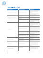
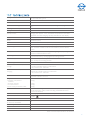
1
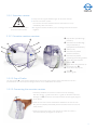
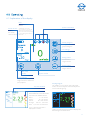
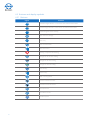
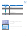
Operating instructions ATMOS® C 051 Thorax English 317.0000.B 2015-07 Index: 05 Further information, accessories, consumables and spare parts are available from: ATMOS MedizinTechnik GmbH & Co. KG Ludwig-Kegel-Straße 16 79853 Lenzkirch/Germany Tel. + 49 7653 689-0 Fax: + 49 7653 689-190 + 49 7653 689-292 (Service Center) [email protected] www.atmosmed.de 2 Table of contents 1.0 Introduction.................................................................................................................................................. 4-7 1.1 Notes on operating instructions................................................................................................................................................. 4 1.2 Intended use.................................................................................................................................................................................... 5 1.3 Function............................................................................................................................................................................................ 7 1.4 Transport and storage.................................................................................................................................................................. 8 1.5 Explanation of symbols................................................................................................................................................................. 9 2.0 Safety advice............................................................................................................................................ 10-13 2.1 Notice.......................................................................................................................................................................................10-11 2.2 Caution............................................................................................................................................................................................12 2.3 Warning...........................................................................................................................................................................................13 3.0 Setting up and starting up...................................................................................................................... 14-18 3.1 Scope of delivery...........................................................................................................................................................................14 3.2 Device overview............................................................................................................................................................................15 3.3 Starting up......................................................................................................................................................................................16 3.3.1 Charging the battery.................................................................................................................................................................16 3.3.2 Secretion canister.....................................................................................................................................................................17 3.3.2.1 Secretion canister overview................................................................................................................................................17 3.3.2.2 Pop-Off valve...........................................................................................................................................................................17 3.3.2.3 Connecting the secretion canister....................................................................................................................................17 3.3.2.4 Exchanging the secretion canister....................................................................................................................................18 3.3.3 Connecting the hose system..................................................................................................................................................18 4.0 Operating................................................................................................................................................... 19-29 4.1 Explanation of the display..........................................................................................................................................................19 4.2 Buttons and display symbols...............................................................................................................................................20-21 4.3 Switch on........................................................................................................................................................................................21 4.4 Leakage test...................................................................................................................................................................................22 4.5 Function..........................................................................................................................................................................................23 4.5.1 Target vacuum............................................................................................................................................................................23 4.5.2 Suction..........................................................................................................................................................................................23 4.6 Release of keylock........................................................................................................................................................................24 4.7 Therapy progress.........................................................................................................................................................................25 4.7.1 Shorttime......................................................................................................................................................................................25 4.7.2 Longtime.......................................................................................................................................................................................25 4.7.3 Transfer of therapy data...........................................................................................................................................................26 4.7.4 Reading out the therapy data.................................................................................................................................................27 4.8 Switch off.........................................................................................................................................................................................28 4.9 User settings.............................................................................................................................................................................28-29 5.0 Warning messages................................................................................................................................... 30-31 6.0 Functions........................................................................................................................................................ 31 6.1 Hose rinsing....................................................................................................................................................................................31 7.0 Accessories, consumables and spare parts.......................................................................................... 32-34 7.1 Attachment of the universal bracket........................................................................................................................................32 7.2 Attaching/removing the ATMOS® C 051 Thorax to/from the universal bracket............................................................33 7.3 Connecting of shoulder belt.......................................................................................................................................................34 8.0 Cleaning and care.................................................................................................................................... 35-37 8.1 General information on cleaning and disinfection...............................................................................................................35 8.2 Cleaning of the device surface..................................................................................................................................................36 8.3 Recommended disinfectants.....................................................................................................................................................36 8.4 Hygiene plan..................................................................................................................................................................................37 9.0 Maintenance and Service........................................................................................................................ 38-39 9.1 Basic information..........................................................................................................................................................................38 9.2 Repairs............................................................................................................................................................................................38 9.3 Handling of rechargeable batteries..........................................................................................................................................39 10.0 Eliminating errors....................................................................................................................................... 40 11.0 Technical data............................................................................................................................................. 41 12.0 Disposal........................................................................................................................................................ 42 13.0 Notes on EMC.......................................................................................................................................... 43-47 1.0 Introduction 1.1 Notes on operating instructions These operating instructions are valid from software-version 1.1. These operating instructions contain important notes on how to operate the ATMOS® C 051 Thorax safely, correctly and effectively. Their reading helps to avoid risks, and also to reduce repair costs and down-time. That increases, amongst other things, the reliability and servicelife of the device. These operating instructions serve not only for new operating personnel to be instructed in the use of the device, but also for use as a reference manual. Full or partial reproduction is subject to prior written approval from ATMOS. These operating instructions must always be kept available near the device. Care and safety inspections in conjunction with professional execution provide for operational safety and readiness for use of your ATMOS® C 051 Thorax and are therefore a must besides regular cleaning. Repair work and safety inspections may be carried out only by expert personnel authorised by ATMOS. By applying only original spare parts you will have the guarantee that operational safety, readiness for work and the value of your ATMOS® C 051 Thorax will be preserved. The product ATMOS® C 051 Thorax bears CE marking CE 0124 according to the EC Directive of the council for medical products 93/42/EEC and meets the basic requirements of annex I of this Directive. The product ATMOS® C 051 Thorax complies with all applicable requirements of the directive 2011/65/EC restricting the use of certain hazardous substances in electrical and electronic equipment (“RoHS”). The declaration of conformity and our general standard terms and conditions can be obtained on our website at www.atmosmed.com. The quality management system applied at ATMOS has been certified according to international standards EN ISO 9001 and EN ISO 13485. Prior to start-up please peruse chapter 2.0 „For your safety“, in order to be prepared for any possible dangerous situations. 4 1.2 Intended use 1.2.1 Intended use ATMOS® C 051 Thorax Name: ATMOS® C 051 Thorax Main functions: Digital device for mobile thoracic drainage Med. indications/ application: Recovery of the neutral vacuum in the intra pleural cavity after the occurrence of a pneumothorax or a pleural effusion by drainage of air and secretion. Drainage of secretion and air after a surgical opening of the thorax. Specification of the main function: The ATMOS® C 051 Thorax drainage suction unit is a digital device for mobile thoracic drainage. The device is meant for the short-term (< 30 d) application on humans. It is portable, grid independent and has an electronic monitoring system with optical and acoustic status displays. The device is applied unsterile. However, the tubing systems and the secretion canister, which have to be applied with the device, are sterile single use products. All thoracic catheter / drains can be applied, which are intended for thoracic drainage in the intended use of the manufacturer. Application organ: Thorax Application time: Short-term use on the patient (< 30 days) Application site: The application site is the clinical area. The application of the device may only be applied by healthcare professionals. The secretion canister and the drainage hose are sterile and disposable, and can be applied in the sterile OT area. Contraindications: No separate application of the canister and the tubing system (this means without basic device) as gravity drainage. No application in ambulances under emergency conditions and in the home care field which is not supervised by healthcare professionals. No suction of flammable, corrosive or explosive fluids / gases. The product is: X active □ not active Sterility: Not in case of the basic device Single use product / reprocessing: Reprocessing for the basic device see notes in the user manual. 5 1.2.2 Intended use ATMOS® C 051 Thorax secretion canister Name: Secretion canister for the exclusive connection to the ATMOS® C 051 Thorax. Main functions: Forwarding of the created vacuum into the drainage hose and finally into the patient-side drain. Collection of the exhausted secretion. Med. indications/ application: Secretion canister for the connection to a digital device for mobile thoracic drainage. Specification of the main function: The vacuum generated by the pump evacuates air and secretion out of the drain. The secretion is collected in the secretion canister whose filling quantity is 800ml. A bacterial filter prevents the potential contamination of the room and the device by bacteria. Additionally it prevents the accidental intrusion of secretion into the pump head. A sterile tubing system provides the vacuum for the patient-side drain. A direct connection to the patient does not exist. With the support of the test measuring hose inside of the tubing system, which is also provided with a filter, the actual vacuum on the drain will be measured. Furthermore the measuring hose is also responsible for the flushing of the secretion hose with atmospheric air. Application organ: Thorax Application time: Short-term use on the patient (< 30 days). Application site: Application environment is a clinical area. The application of the canister may only be applied by healthcare professionals. The secretion canister and the drainage hose are sterile and disposable and can be applied in the sterile OT area Contraindications: No application of the canister with other low vacuum devices than ATMOS® C 051 Thorax. No separate application of the canister as gravity drainage. The product is: □ active X not active Sterility: Sterile Single use product / reprocessing: Sterile single use product 6 1.3 Function The ATMOS® C 051 Thorax is an exceptionally handy, mobile, digital thoracic drainage suction device. The device is operated via an electrical, maintenance-free membrane pump. During operation the pump creates a vacuum within the suction hose and the secretion canister due to which secretion and air can be drained by the hose system. The pump is controlled digitally and therefore secures that the chosen required vacuum value is stable. The air flow, which is measured in real-time, is displayed in numbers. The secretion is collected in the secretion canister. Its capacity is 800 ml. With the aid of the measuring and rinsing hose in the hose system the vacuum at the end of the hose system is measured. Via the touch screen display the required vacuum can be set manually. The suction power is regulated automatically. The hose system is rinsed with air at regular intervals to prevent the collection of debris in the secretion hose. This measure also prevents secretion from intruding into the measuring and rinsing hose or that a syphon effect is created. The device is equipped with a rechargeable battery. A charging unit which is located within the suction device guarantees for the secure charging of the battery. Therefore it is impossible to overcharge the battery. A bacterial filter located in the secretion canister prevents the intrusion of bacteria and secretion into the aggregation space. The device is equipped with a carrying strap. The strap allows for mobility and the fastening of the device e.g. to the patient’s beds. As an accessory a universal connection can be ordered separately. 7 1.4 Transport and storage The transport of the device may be effected only in a dispatch carton upholstered and offering sufficient protection. Please document and report damages in transit immediately. For complaints or return deliveries, please use the enclosed form QD 434. The form QD 434 can also be downloaded from: www.atmosmed.de The unit must be allowed to stand for up to six hours at room temperature prior to starting up for the first time following transport at temperatures below freezing. The unit may not be operated if it has not acclimatised as this might damage its diaphragms. 8 Ambient conditions: Transport/Storage: -20...+50 °C; 5...95 % humidity non-condensing at air pressure700...1060 hPa Operation: +5...+35 °C; 20...80 % humidity non-condensing at air pressure700...1060 hPa max. 3000 m Operation altitude: 1.5 Explanation of symbols Short cuts / symbols contained in this manual Follow the arrows whilst proceeding, sequence ■ General information Please press where the dot indicates ● Numeration Turn, shift ... in this direction Please read, important information → Subnumeration Replace Check Move, plug ... in this direction click Engage, check correct fit 2 Multiple use of components marked with 2 is not allowed. This product is not resterilisable. In case of multiple use this component looses its characteristics and there is a high risk of infection. Pictures contained in this manual ! Warning, special diligent notice! Important information Symbols of ATMOS® C 051 Thorax & Accessories Application part type BF SN Serial number REF Order number The CE sign shows that this product meets the appropriate requirements of the EC Directives. Class II Electricity fuse Manufacturing date Please observe operating instructions! 9 2.0 Safety advice 2.1 Notice NOTICE Damage to the device due to improperly installed protective contact socket NOTICE The ATMOS® C 051 Thorax was produced in accordance with IEC 60601-1/EN 60601- it is a device of VDE-safety class II. The device should only be connected to a properly installed protective contact socket. Prior to first use compare the normal voltage of the device (see indication label on the backside of the device) with the local mains voltage. ATMOS cannot guarantee perfect functioning neither will it be liable for damage to people or property If: NOTICE any non-original ATMOS parts are used, the user instructions given in this manual are not followed exactly or are disregarded, improper use assembly, resetting, alterations, extensions and repairs are not carried out by people authorised by ATMOS Electromagnetic compliance, damage to the device! The ATMOS® C 051 Thorax should not be operated with devices not complying with the requirements of standard EN 60601-1„Medical Electrical Equipment“ and EN 60601-1-2 „Electromagnetic Compatibility“ (Medical Electrical Equipment) NOTICE Damage to the device due to low temperatures NOTICE After transport in temperatures below freezing point the device must be acclimatised for up to 6 hours. If the device is not acclimatised it should not be operated as the membrane in the aggregate could get damaged. Damage to the device due to tilting The device and the canister must be used upright at all times. If the device should tilt it must be placed upright again in order to guarantee faultless operation. If you are insecure whether the canister works properly we advise you to replace the canister so as to ensure the patients’ safety. NOTICE Damage to the device due to heat The device and the canister should not be dried in a microwave oven. The mains cable and the device must be kept away from hot surfaces. 10 The device may only be operated at room temperature and should not be subjected to direct solar irradiation as this could lead to errors. NOTICE Legal advice NOTICE Appropriate operation NOTICE The user should be able to reach the operating panel comfortably and should have a good view on it at all times. The canister may not be used without the device (gravity drainage). The device may only be used by trained professionals. The removal of the canister from the device during the therapy may only be performed by trained professionals which act in conformity with internal regulations. The ATMOS® C 051 Thorax is a medical device which is subject to special safety regulations. It must to be set up and put into operation in accordance with the EMC regulations included in this manual. Portable and mobile RF communication devices (mobile phones) may affect the performance of the device. A second functioning device (consumables included) must be available for every patient whose condition could become critical if the device in use should get damaged. The device may not be operated in MRI scanners (magnetic resonance imaging). The device may not be carried at the hose system. The device supports the therapy of the patient it is not a substitute for the doctors‘ diagnosis. The patient should be supervised constantly in accordance with the internal rules of the hospital. Prior to the removal of the hose connector the patient hose must be pinched off. Advice on disposal NOTICE The operating instructions are in conformity with the device specifications standards on safety at the time of printing. The circuits, processes, names, software programmes 01.28 and devices are all covered by trade mark rights. US law restricts sale of the device to physicians or ordering through them. Dispose of the packing material in a proper manner. Attention must be paid to all hospital protocols regarding disposal and infection control. Wrong evaluation Prior to each application the device should be checked for leakages (peruse chapter 4.4 – leakage test). Leaking connections could lead to a wrong evaluation of the patients status and could prolong the therapy. Thus do check all connections for leakages to prevent the intrusion of additional air. 11 2.2 Caution CAUTION Danger of injury CAUTION Danger of injury CAUTION A bent hose could cause a pressure pneumothorax. The bending of the patient hose leads to an interruption of the therapy and incorrect measurements. The hose should not be bent. Danger of injury 12 If the fluid level in the canister is too high it could cause a blockage and thus a pressure pneumothorax. Exchange the canister when the maximum filling level is reached to secure the patients safety. Defective components in the system have to be exchanged immediately. The patient hose connection should be checked regularly for correct functioning. Danger of injury CAUTION A misplaced drainage system and a misplaced patient hose could hinder the drainage of air and liquids. A complete blocking of the system during the drainage of liquids and air could cause a rise in pressure and thus lead to a pressure pneumothorax. Place the drainage system below the thorax and check the patient hose for bends and cloggings which could hinder the drainage of liquids and air. Immediate reaction is required in case of the warning message "vacuum too low". Prior to exchanging the secretion canister the drain at the patients side must be clamped so that a continuous vacuum is always available at the patient. A vacuum over -50 mbar could cause pain and injury to the patient. Only under medical indication a vacuum over -50 mbar may be adjusted. 2.3 Warning WARNING WARNING WARNING Electric shock due to damaged connecting cables Prior to use check the device and connecting cables for damages. Damaged cables must be replaced! Electric shock due to voltage Prior to disconnecting the battery from the mains pull the plug from the electrical socket, after that you can disconnect the connecting cable from the battery. Do not modify the device. Please pay attention to the period tests in chapter "Maintenance and service" on page 38. Assembly, repairs and period tests may only be carried out by authorized persons. Electric shock due to voltage WARNING Disinfectant or secretion should not enter the device or battery. If disinfectant has penetrated the device, then it must be dried thoroughly and subsequently an efficiency control must be conducted. It should be tested if the target vacuum can be reached in a closed system, as well as if there is a flow > 4 l/min after a short while, when the system is open. If not, the device must undergo a service check before it resumes operation. If secretion has entered or is sucked into the device then it must be sent to the manufacturer or an authorized service partner. The mains adapter should not get wet. Don´t take a shower / bath with the device. Danger of explosion due to unobserved ambient conditions The ATMOS® C 051 Thorax may only be operated in rooms used for medical purposes, but not in areas subject to explosion hazards or in oxygen rich environments. Explosion hazardous areas may result from the use of flammable anaestetics, skin cleansing agents and skin disinfectants. Pay attention to the ambient conditions specified in chapter 11.0. WARNING Risk of infection This product is not re-sterilizable. Repeated reuse of components which are marked with 2 is forbidden. In case of repeated reuse these components lose their function and there is a high infection risk. Repeated reuse of canister and hose systems can lead to infections. Canister and hose system should only be used once on every patient. For hygienic reasons we recommend an exchange of both canister and hose system at the same time. 13 3.0 Setting up and starting up 3.1 Scope of delivery The ATMOS® C 051 Thorax was subjected to thorough testing prior to packaging and shipment. On receipt of the goods please check the package for any possible damage and compare the contents for completeness ( see bill of delivery). Description Basic device Recharger Mains cable Operating instructions Carrying strap Strap holder Quick guide 14 3.2 Device overview Front side: 4 5 6 6 1 3 Touch screen (touch-sensitive display) On/off sensor Charging socket Secretion canister release Light sensor Clips for carrying strap 2 Back side: 13 12 11 7 8 8 9 317.0000.0 ATMOS C 051 Thorax Connection for secretion canister Connection for clips Identification plate Canister guide 11 Measuring and rinsing hose connection 12 Cover cap USB-B (no function for user) Connection for USB flashdrive (therapy data-transfer) 13 10 Only use the USB-connection for the transfer of therapy data. A software update may only be performed by ATMOS or an authorized service person. 15 3.3 Starting up Remove the device from the box. Check whether the voltage values on the identification plate match with the available mains voltage. Prior to the first start up peruse the safety notifications in chapter 2. The battery must be fully charged prior to the first use. Charging time approx. 2.5 hours. Always place the device on a flat, save surface. Plug in the mains cable to recharge the battery. After transport in temperatures below the freezing point the device must be acclimatised for up to 6 hours. If the device is not acclimatised it may not be operated as the membrane in the aggregate could get damaged. Always have at least one more secretion canister at hand as the device can only be operated with the specific ATMOS secretion canister. 3.3.1 Charging the battery Each bar of the symbol represents 20% battery charge. Attention! Prior to the first start up of the ATMOS® C 051 Thorax the battery must be fully charged. Only the enclosed battery recharger (GTM 21097-5012) from ATMOS may be used. Advice on the handling of the battery can be found in chapter 9.3. Correct handling of the rechargeable batteries prolongs their maximum service life. Rechargeable batteries are wearing parts and therefore excluded from the general warranty. The device should be recharged in a cool place without direct solar irradiation. At ambient temperatures above 25°C the charging time could be prolonged drastically. Defects which occur due to improper handling of the device are not covered by the guarantee. Caution: If the battery temperature is higher than 35°C it can no longer be charged. Plug the recharger into the charging socket of the ATMOS® C 051 Thorax. Connect the recharger to the country-specific mains cable. Plug the mains plug into the socket. The ATMOS® C 051 Thorax displays symbol on the display. the blinking symbol does not When the battery is fully charged (the blink anymore) remove the plug from the socket. After that remove the recharger plug from the charging socket of the ATMOS® C 051 Thorax. ! As soon as the battery charge level is less than 20%, the drainage unit displays a warning window and triggers an audible warning message (peruse chapter "5.0 Warning messages"). Charge the battery in order to continue the therapy without interruption. If the battery is too low for further operation of the device the ATMOS® C 051 Thorax switches off automatically. The battery of the ATMOS® C 051 Thorax can also be charged when the device is switched off. The state of charge can be seen on the display. 16 3.3.2 Secretion canister ! Always use the original ATMOS single use secretion canister Vacuum connection system The vacuum connection between device and canister is set up immediately after connection! For hygienic reasons we advise you to exchange hoses and canister together. Important safety instructions on the secretion canister 3.3.2.1 Secretion canister overview Pop-off valve (10 mbar high pressure) Connection to the drainage unit (protected by a hydrophobic bacterial filter) Scales (in ml) Connection to patient (secretion channel) Connection to patient (measuring and rinsing system) Cover lid of the secretion channel Cover lid for the connection to the suction unit Cover lid for the pop-off valve Canister guide 3.3.2.2 Pop-off valve The pop-off valve is a protection against the occurrence of high pressure which could lead to a tension pneumothorax. The valve opens at a high pressure of ≥10 mbar within the canister. 3.3.2.3 Connecting the secretion canister 1. Cautiously withdraw the secretion canister from the wrapping. Affix the canister´s guide to the device´s guide on the back side of the drainage unit (see device overview). Hold the canister slightly angled to the device. 2. Push the secretion canister towards the ATMOS® C 051 Thorax until they connect palpably and audibly and the release button returns to its initial position. 3. Perform a slight pull-check on the canister to make sure that it is connected securely and tightly to the device. 17 3.3.2.4 Exchanging the secretion canister 2. 1. 1. Press the blue operating element ( device overview) on top of the device to release the canister. 2. Hold the secretion canister slightly angled and pull upwards to remove it. 3. Place the secretion canister safely on an even surface. 4. Release the 2 Luer-Lock connections by a cc rotation to separate the secretion canister from the hose system. Pay attention as secretion could be found in the connection space. 5. Remove the blue cover lid and cover the upper Luer-Lock connection with it (secretion channel). 6. Remove the yellow cover lid and cover the connection to the drainage unit with it. 7. Remove the black cover lid and cover the pop-off valve with it . The used secretion canister is now ready for disposal. 8. Follow the instructions in chapter 3.3.2.3 to connect a new secretion canister. 3.3.3 Connecting the hose system Measuring and rinsing hose Hydrophobic bacterial filter Luer-Lock 4 mm Secretion hose Luer-Lock 6 mm 1. Remove the sterile hose system from the sterile wrapping. 2. Connect the Luer-Lock with the bacterial filter to the lower canister connection ( on the secretion canister) by a cw rotation. 3. Connect the Luer-Lock connection with the larger diameter to the upper connection of the canister ( on the secretion canister) by a cw rotation. 4. Perform a leakproof test (see chapter 4.4) 5. Use the sterile hose connector, supplied with the hose system, to connect the hose system to any drainage catheter of your choice. Alternately you can also use conventional sterile y-connectors or hose connectors. 18 ! 4.0 Operating 4.1 Explanation of the display Flow Display of the actual fistula Actual vacuum Display of the actual vacuum value System information ATTENTION: This is the current value. In the case of a discontinuous fistula, the value can decline temporarily to zero although the fistula still exists. Therapy progress Changeover to the graphic diagram User settings Setting button Increases the target vacuum Setting button Decreases the target vacuum Start / Stop therapy Keylock manual Target vacuum Display of the preadjusted target vacuum to which the pump adjusts Key lock activated Day/Night Mode The ATMOS® C 051 Thorax has a day/night mode, the device adjusts automatically to the environmental lighting. Flow displayed as bubbles Each additional coloured bubble represents an additional flow. None: 0 - 20 ml/min Green: 30 - 50 ml/min Yellow: 60 - 620 ml/min Orange: 630 ml - 1,00 l/min Red: 1,01 l/min to maximum Up to 1,00 l/min the flow is displayed in ml/min. Under low ambient light conditions display has dark background illumination. 19 4.2 Buttons and display symbols 4.2.1 Buttons Figure Function Decrease target vacuum / in the menu: decrease selected value Increase target vacuum / in the menu: increase selected value Graphic diagram of the therapy Open the user settings Save entry Confirm information Back / Exit menu Warning / suppress the warning Changeover to vacuum scaling Changeover to time scaling Changeover to flow scaling Start therapy Stop therapy Hold / restart graphic Increase maximum of axis Decrease maximum of axis Scroll up the list Scroll down the list Activate keylock 20 4.2.2 Display symbols Figure Function Battery status display / charging indicator Keylock active Therapy recording in progress Therapy on hold Therapy in progress Upcoming warning suppressed Safety check required 4.3 Switch on 1. To switch on the ATMOS® C 051 Thorax please touch the sensor above of the symbol for 2 seconds. 2. The welcome monitor appears with the software version number in the bottom right corner. 3. After a short while the leakage test (chapter 4.4) starts automatically. 4. Subsequently "Therapy progress" will appear in the display. By pressing the buttons you can start a new therapy recording or continue recording. 5. The main display appears. The device is now ready for use. 21 4.4 Leakage test Following device startup the leakage test starts automatically. The hose attachment towards the drainage catheter should already be sealed with a sterile plug when starting up the device. Alternatively the thorax catheter can be clamped near to the patient. Do not clamp the ATMOS hose system. If the leakage test is error-free, the message „Leakage test OK“ appears. Now you can remove the plug from the hose. By pressing the button you will reach the main menu. If the leakage test is faulty, the message „Leakage test failed“ appears. You now have the possibility to a) repeat the test b) abort the test by pressing the respective buttons on the screen. ATTENTION: If the leakage test is operated accordingly the leakage should not be ignored. The intention of "abort the leakage test "is to skip the test if an standard test under given conditions is not possible. 22 4.5 Function 4.5.1 Target vacuum Please note, an adjusted target vacuum over -50 mbar may cause pain and injuries to the patient. On the main screen the target vacuum can be set directly by pressing the and buttons. ATTENTION: The change of the target vacuum is immediately effective. There is no confirmation necessary. The target vacuum can be freely selected between -5 and -100 mbar in steps of 1 mbar. If the buttons the and are pressed permanently, the increase / decrease will be accelerated. The target vacuum of -20 mbar is preset when starting the device. If target vacuum is adjusted over -50 mbar the notice appears ,,High target vacuum is set “. 4.5.2Suction When the device is switched on the pump is not activated. This is visible due to the symbol in the right upper corner. By pressing the button the pump starts. The symbol in the right upper corner of the main screen shows that the pump is running. By pressing the button the pump will be stopped. The ATMOS® C 051 Thorax has a vacuum adjustment. This means, that the integrated pump only runs, if the actual vacuum doesn't correspond to the target vacuum. On the other hand the pumps performance depends on the difference between the actual vacuum and the target vacuum. The vacuum is measured at the patient side of the hose system. 23 4.6 Keylock The ATMOS® C 051 Thorax has an automatic keylock. 1. Automatic activation of the key lock If the settings are not changed for a defined time, the keylock will be activated automatically (default factory setting 5 minutes, individually adjustable in the user settings). This will prevent unintentional operation. 2. Manually activate the key lock The key lock can be manually activated after all the therapy values are set and the therapy is started. Press the -symbol to activate the key lock. The display symbol appears above the Flow-display and shows an activated key lock. 3. Deactivate the key lock A quick touch to the display and then the first contact point appears . By touching the display symbol the second contact point appears . By a repeated touching of this display symbol the key lock symbol above is deactivated (see first display image). Now you can operate the system again. and If you do not touch both the symbols within 6 seconds the key lock remains activated. The deactivation process can be started by a repeated touching to the screen. 24 4.7 Therapy progress The ATMOS® C 051 Thorax has 2 graphical diagrams to analyse the development of Air-Flow and actual vacuum. Selection menu By selecting the button you reach the graphical diagram modus. By pressing the buttons you can select the modus of your choice e.g. long / shorttime. 4.7.1 Shorttime The graphical diagram starts by selecting the menu. In this modus the real measurements (flow, vacuum) from the last 30 seconds can be shown. Therefore you can visualise cough tests and other proceedings. By pressing the button the diagram can be frozen to enable a graphical interpretation. When you press the button again the shorttime diagram is restarted. By pressing the button you will return to the main menu. 4.7.2 Longtime In the longtime modus the complete therapy progress can be visualised. The scaling can be switched between time and flow. You can reach the different scalings by pressing the , button or the button. The scale can be increased or decreased by pressing the button or the button Time scaling: - The endpoint on the right side of the graphic is always the actual point of time. - The scaling can be selected in 7 steps, between the display of the past 60 minutes and the last 12 days. - A vertical line shows when the therapy was interrupted. Flow scaling: - The scaling can be selected between 0 – 0,55 l/min and 0 – 5,5 l/min in 4 steps. Vacuum scaling: - Scaling can be selected in 3 steps between 0 - 110 mbar (= cm H2O) and 0 - 22 mbar (= cm H2O). 25 4.7.3 Transfer of therapy data You may transfer the therapy data to a USB flashdrive. The therapy data is saved as a PDF- and Excel-file. If you continue the therapy after the data transfer, the data is recorded. The transmitted data is not deleted. If you are starting a new therapy, the previous data will be overwritten. Start transfer Clamp the suction hose near the step connector close to the patient. Stop the current therapy. Connect the USB flashdrive. The device prepares for the therapy data transfer. In order to start the transfer confirm the query on the device with „Yes“ If you do not wish to start the transfer press „No“. Abort Remove the USB-flashdrive. Now you return to the main screen. Therapy data transfer The USB flashdrive must stay connected during the whole data transfer. The software indicates the duration and status of the transfer. The transfer can take up to 3 minutes. Do not abort the transfer even if the percentage reading does not increase. Complete data transfer As soon as the therapy data is transferred then the USB flashdrive may be removed. Now you return to the main screen. Continue with the therapy. Reopen the clamp at the suction hose. 26 4.7.4 Reading out the therapy data Connect the USB flashdrive to PC. Open the folder on the USB flashdrive. This folder contains a PDF file and an excel file. Open the PDF file. Fill in the desired Information: 1 Patient data 2 Diagnosis 3 Description of the secretion Following information can be seen in the report: 4 beginning and end of recording, flow at beginning and end of recording 5 file name und device ID 6 graphical diagram of therapy data Therapy Report ATMOS® C 051 Thorax File name: ATMOS_C_051_THORAX_ID0C1C_20110212_063107.pdf Device ID: 0C1C 5 Patient: 1 Diagnosis: 6 2 Secretion: 3 Start date: 12.02.2011 / 04:28 Air leak: Flow @ Start 0.01 l/min End date: 4 12.02.2011 / 06:31 Recording time: 00:02:00:00 Flow @ End 0.01 l/min 27 4.8 Switch off To switch off the ATMOS® C 051 Thorax stop the therapy and touch the sensor for 2 seconds. The enacting monitor appears and the device shuts down. 4.9 User settings For accessing the user menu please press the control panel. Please press the control panels and moving up and down in the menu selection. for For entering a selection menu press on the text box. These control panels can be found in every settings menu: Press the control panel to return to the user settings. ATTENTION! The selected data are only saved if you press the memory key . In the user settings the following positions can be selected: System language Vacuum unit 28 The language can be adjusted with or . The vacuum unit can be adjusted or . with Standard - vacuum When the device is started the standard-vacuum is automatically preadjusted. The standard-vacuum can be or . adjusted with Period time of hose rinsing Keylock activation time Keytone Date Period time of hose rinsing can be or . adjusted with Key lock activation time can be or . adjusted with The keytone can be activated or deactivated by pressing and . By pressing the three control panels (Day, Month, Year), you may enter the individual settings. Now adjust the Date with . Time or By pressing two control panels (Hour or Minute), you may enter the individual settings. Now adjust the time with . or 29 5.0 Warning messages ! In the event of a warning message the key lock is removed automatically! In the event of a warning message the system switches to the warning-menu automatically. An error indication is displayed. This indication contains advice for the removal of the cause of error. The acoustic warning message is triggered at the same time. No warning message appears during the startup and the data transfer. Display Cause of error Troubleshooting If the required vacuum cannot > Check for leakages and / or be reached an acoustic alarm blockages and optical display of the warning > Connections message „vacuum too low“ is > Secretion canister displayed. Possible reasons for > Drainage hose this error indication are: leakage, blockage of the bacterial filter in the measuring channel, clogging, a bend in the drainage hose, liquids were > Contact the ATMOS service sucked into the pump. The measurement of an excessively > Check for blockages high vacuum results in the display of > Connections the warning message “vacuum too > Secretion canister high”. > Drainage hose Possible reasons for this error indication: The vacuum settings were changed while the therapy was stopped, the venting valve is defect, there are further vacuum sources in the drainage area. >Remove vacuum sources 30 If the voltage of the battery falls below a specific value the error indication for “battery low” is displayed. Connect device to the battery recharger. The battery is charging and the soc (state of charge) is indicated in the display. If the device is in a tilted position the warning „Device in critical tilt” appears. Place the device in an upright position. The warning signal is automatically deactivated. Display Cause of error If the therapy hasn`t started after initial operation the error indication for "inactive therapy" is displayed. Troubleshooting Start therapy by pressing the button. A safety check (inspection according to the manufacturers specifications) is required every year. This will be displayed on the device. Low battery capacity appears in the display. Battery must be replaced by the service. If the target vacuum is adjusted over-50 mbar a notice appears ,,High target vacuum is set“ 6.0 Functions 6.1 Hose rinsing The ATMOS® C 051 Thorax has an automatic hose rinsing function which works periodically. The rinsing process transports secretion located in the secretion hose into the secretion canister. The rinsing is performed by opening a valve located in the measuring channel. The manufacturers default setting for the period between 2 rinsing cycles is 5 minutes. 31 7.0 Accessories, consumables and spare parts 7.1 Attachment of the universal bracket (Accessories) Turning the universal bracket: The universal bracket can be attached – horizontally and vertically - to plates (e.g. table boards), pipes and stands with a diameter up to 40 mm. Pull the fixing pin from the fixation at the bottom side of the universal bracket. Turn the holder clamp until the fixation pin clicks into place at the next fixation. ! Attention! Ensure that the fixing pin has correctly clicked into place before attaching the thoracic drainage unit to the universal bracket. Attaching the universal bracket Twist the turning knob of the universal bracket anticlockwise until the clamp is attached to the desired fixture. Twist the turning knob clockwise to secure the universal bracket. ! 32 Attention! Ensure that the universal bracket is firmly attached to the desired fixture. 7.2 Attaching/removing the ATMOS® C 051 Thorax to/from the universal bracket ! Attention! Firmly hold the vacuum unit during the whole process. Place the ATMOS® C 051 Thorax onto the universal bracket. Ensure that the thread at the bottom of the vacuum unit is positioned directly above the fixing screw of the stand holder. Turn the fixing screw clockwise to fix the ATMOS® C 051 Thorax. To remove the ATMOS® C 051 Thorax release the fixing screw by turning anticlockwise. The thoracic drainage unit must always be attached horizontally. 7.3 Connection of shoulder belt 7.3.1 Strap holder The strap holders on the back of the device are already mounted on delivery. If you do not require the strap holders they can be easily removed with a standard screwdriver. 33 7.3.2 Attaching the carrying strap 4 3 1 2 + Carabiner for the attachment to the clips on the device. 5 For use as a shoulder strap + Carabiner for the attachment to the clips on the device. For use on a patient’s bed + Fastener for the bed attachment Attaching the carrying strap: Take a carabiner and attach it to one of the clips on the drainage unit. Attach the second carabiner to the second clip on the drainage. Now the ATMOS® C 051 Thorax can be worn over your shoulder. Attaching the drainage unit to a patient’s bed: To attach the device to a patient’s bed exchange the carabiner with carabiner . Now you can attach the drainage unit to the patient’s bed by simply closing the fastener . Removing the drainage unit from the patient’s bed Press the release on the sides of the fastener. Pull both ends apart. 34 8.0 Cleaning and care 8.1 General information on cleaning and disinfection Prior to cleaning Medical devices such as the ATMOS® C 051 Thorax must always be ready for use and must function reliability. Therefore prior to every application: if necessary ! The way the device is used determines its reliability and safety. These hygiene measures are indispensable for protecting the patient and the user and for maintaining the functional reliability of the device. ! Prior to cleaning please remove the mains cable, power supply and charging plug from the device. ! The described measures for cleaning and disinfection do not replace the valid rules for operating the device! ! Some disinfectants could cause discoloring to some of the plastic parts. ! Avoid the penetration or liquid entering the drainage device, especially in the connections on the back of the device. ! Please observe the instructions for use prescribed by the manufacturers of disinfectants. Pay attention regarding their concentration suitability for use and the contact time. ! Do not use disinfectants containing concentrated organic or anorganic acids or bases, since these may cause corrosion damages. disinfectants containing chloramides or phenol derivatives since these may cause stress cracks in the material used for the housing of the unit. During all work disposable gloves must be worn. For disinfection, all the surface disinfectants stated in chapter 8.3 „Recommended disinfectants“ are suitable. Prior to cleaning the device please remove and dispose all disposable parts like secretion canister, and hoses. Prior to being used on a new patient all parts which come into contact with secretion e.g. secretion canister hoses etc, must be disposed. It is important that disinfectant does not enter the device. Do not use a spray disinfectant directly on the device, but spray it on a cloth (only damp not wet). During cleaning and disinfection the device must be switched off. Do not switch the device back on until the cleaning and disinfectants on the surface have dried completely. We recommend you to document any maintenance work and also any exchange of parts. 35 8.2 Cleaning of the device surface Prior to using the device on a new patient the complete device surface must always be cleaned with a damp (not wet) cloth and disinfected with a surface disinfection solution. In case the device is being used by the same patient the surface should still be cleaned. At least once every week with a damp (not wet) cloth and afterwards be disinfected with a surface disinfectant. ! Attention! The device should never be autoclaved, rinsed under running water or immersed into any liquids! 8.3 Recommended disinfectants Disinfectant Ingredients ATMOS Green & Clean SK (application solution) Alkyldimethylbenzylammoniumchloride Dialkyldimehtylammoniumchloride Alkyldimethylethylbenzylammoniumchloride Dismozon plus (application solution) Magnesium peroxyphthalate Hexahydrate Kohrsolin FF (application solution) (in 100 g) <1 g <1 g <1 g Manufacturer Metasys, Rum (Austria) 95,8 g Bode Chemie, Hamburg Glutaral Benzyl-C12-C18-alkyldimethylammoniumchloride Didecyldimethylammoniumchloride 5g 3g Bode Chemie, Hamburg Kohrsolin extra (application solution) (Ethylendioxy)dimethanol Glutaral Didecyldimethylammoniumchloride 14,1 g 5g 8g Bode Chemie, Hamburg Mikrozid sensitive wipes Quaternary Ammonium compounds 0,26 g Schülke & Mayr, Norderstedt Perform (application solution) Pentakalium bis(peroxymonosulphate)bis(sulphate) 45,0 g Schülke & Mayr, Norderstedt Sanicloth active (wipes) Didecyldimethylammoniumchloride 0,45 g Ecolab, Düsseldorf Incidin active (1% application solution) Peracetic acid 0,05 g Ecolab, Düsseldorf Bacillol 30 Foam Propam-2-ol Ethanol Propan-1-ol N-Alkylamino-propylglyein 10,0 g 14,0 g 6,0 g <1g Bode Chemie, Hamburg 3g All cleaning and disinfectant agents with the above mentioned ingredients are also suitable for cleaning the basic device. Discoloration may result if disinfectants containing aldehydes and amines are used on the same object. ! 36 Don´t use disinfectants with alcohol (Exception: Bacillol 30 Foam). 8.4 Hygiene plan WHAT HOW X NOTES After each patient X Drainage unit Monthly S Weekly D Daily C After each procedure R WHEN X X Manual wipe cleaning X X Manual wipe disinfection Canister X X Single use product -> not suitable for reprocessing exchange after use 2 Hose system X X Single use product -> not suitable for reprocessing exchange after use 2 R= Removal, C= Cleaning, D= Disinfection, S= Sterilisation 37 9.0 Maintenance and service 9.1 Basic information Maintenance, repairs and period tests may only be carried out by persons who have the appropriate technical knowledge and are familiar with the product. To carry out these measures the person must have the necessary test devices and original spare parts. ATMOS recommends: work should be carried out by an authorized ATMOS service partner. This ensures that repairs and testing are carried out professionally, original spare parts are used and warranty claims remain unaffected. Carry out an inspection according to the manufacturers specifications every 12 months (Germany: safety check according to §6 Medical Device Operator Ordinance). This check should also include a check of the battery capacity as well as all parts for wear or damage. Further regular maintenance work is not required. It is understood that the vacuum unit and its application parts are regularly and thoroughly cleaned and disinfected, and that it is operated in accordance with the instruction manual. Please observe any national and international regulations applicable for your institution 9.2 Repairs The following problems could require repairs by the manufacturer or an authorised service partner. Please contact the manufacturer or authorised service partner by telephone before sending in the unit. Liquid has penetrated the device; Significant decrease of battery capacity; Sudden occurrence of abnormal displays on the screen; Sudden occurrence of abnormal noises; Operational faults or malfunctions which cannot be remedied using the measures as stated under “Remedy of operational faults and malfunctions”. Measures when sending in the vacuum unit: If the vacuum unit must be sent to the manufacturer or an authorised service partner – after respective consultation – please ensure the following: Please send in the device complete with charger and mains cable (see scope of delivery); Remove all single-use and/or consumables; Thorough cleaning and disinfection; Air-tight packaging; Accompanied by a detailed error description. 38 9.3 Handling of rechargeable batteries Rechargeable batteries are wear parts with a limited service life. Under optimal condition of use, rechargeable batteries are usually depleted after approx. 500 charge cycles, and should then be replaced. Handling of the device, including the batteries, significantly affects the service life of the batteries. Nonobservance of the following recommendations may significantly decrease service life. )) )) )) )) )) )) )) Always store the batteries in a cool and dry place (room temperature 18 - 25° C). Always store the device with batteries at a charge status of 20 - 40 %. Due to self-discharge, the batteries should be recharged every 4-5 months. Never cover the device; never expose the device to direct sunlight; and never charge, operate or store the device in close vicinity to heaters. Always charge the batteries using the respective charging equipment. Overcharging will destroy the batteries! The lifetime of Lithium-Ionic batteries mainly depends on the ambient temperature. On principle batteries are depleted after 2.5 years. New batteries should be fully charged prior to first use. As ATMOS has no influence on the handling of the device, batteries are excluded from the general guarantee. A function guarantee of 6 months is effective. ! Attention! The use at other charging accessories could result in the risk of explosion. 39 10.0 Eliminating errors Description Device cannot be switched on Battery does not recharge. Charging symbol does not light up despite proper connection to the mains cable Possible causes Measures Battery completely empty Connect the battery recharger to the device to recharge the battery, Note that the progress can be checked in the upper left hand corner of the display Fuse defect Control fuses Mains cable defect or not plugged in properly Control mains cable Mains cable or battery are internally defect Device must be checked by the manufacturer or an authorised service partner Leakage Check all the hoses and the canister for leakages. Check whether the pop-off valve is loose and fix it if necessary.. Blockage in the hose system Remove the blockage if necessary. Remove the measuring channel from the connection to the canister. If the filter in the measuring channel is blocked exchange the hosing system Filter/ overflow protection in hose / filter is blocked Check hose and filter. If the filter is wet exchange canister and filter Liquids sucked into pump The device must be checked by the manufacturer or an authorised service partner Excessively high vacuum applied from the outside Check for correct hose connections Venting valve defect Device must be repaired by the manufacturer or an authorised service partner Battery almost empty Connect the battery recharger to recharge the battery. The progress is displayed in the upper left hand corner of the display. „Vacuum low“ „Vacuum too high“ „Battery low“ Battery empty System shut down 40 Connect the battery recharger to recharge the battery. The progress is displayed in the upper left hand corner of the display. 11.0 Technical data Voltages 100- 240 V~, 50/60 Hz IEC socket IEC320, type 14 Power consumption -- Power input Max. 60 W Direct current voltage 12 V DC +/- 2 %, max. 5 A via cable,1.8 m length with plug 5.5 x 2.5 mm Rechargeable battery, built-in Lithium-ionic, 14.4 V nominal, 2250 mAh Charger GTM 21097-5012 Operation time Charging time approx. 2.0 h, at ambient temperatures, automatic switchover to trickle charging, capacity indication on the display Operation altitude Max. 3000 m Pump Membrane pump Flow Max. 5 +/- 0,5 l/min freeflow (without filter, damper or hoses) Vacuum Max. -100 mbar, limited mechanically and by electronic control Vacuum regulation Electronically controlled, max. -100 mbar, min -5 mbar in steps of 1 mbar, secretion canister must be connected for precise vacuum control Display Graphic display, color, with background lighting, display of target vacuum in mbar and flow in l/min Operating conditions On- Standby, Off - Pump (therapy) Simultaneous battery recharging and operating possible Data memory Internal memory for therapy data: 2.5MB up to 12 days of recording possible Earth leakage current Max. 0.5 mA Ambient conditions transport and storage -20…+50°C 5...95 % air humidity without condensation at air pressure 700...1060 hPa Ambient conditions operation / charging +5…+35°C 20..80 % air humidity without condensation at air pressure 700...1060 hPa Dimensions HxWxD 164 x 206 x 95 mm without canister depth with canister: 142 mm Weight: - Drainage unit (without canister) - Secretion canister - Unit with canister - Power supply and mains cable 1.06 kg 0.28 kg 1.34 kg 0.50 kg Period tests Inspection according to the manufacturers specifications every 12 months (Germany: safety check according to §6 Medical Device Operator Ordinance). Protection class (EN 60601-1) I, at charging mode for EMV, II, at battery mode Application part Type BF Degree of protection IP 33 Classification acc. to appendix IX EC Directive 93/42/EEC IIa CE marking CE 0124 UMDNS-Code 10-218, suction device thoracal GMDN-Code 36787, suction device thoracal Issue of Technical Specifications: 06.08.2013 41 12.0Disposal Pay attention to country-specific regulations for disposal (e. g. waste incineration). Device and accessories must be decontaminated prior to disposal as secretion residuals could lead to danger of a third party. The materials must be separated carefully. The materials of the housing can be recycled completely. The ATMOS® C 051 Thorax contains a Lithium-Ionic battery, which must be disposed of in accordance with the valid guidelines. Disposal within the EU The suction device described above is a high-quality medical product with a long service life. After its life cycle it must be disposed of professionally. According to the EU directives (WEEE and RoHS) the device may not be disposed in domestic waste. Please observe existing national laws and rules for disposal of old devices. Disposal within the Federal Republic of Germany In the Federal Republic of Germany the law for electrical devices (ElektroG) rules the disposal of electrical devices. It must be assumed that those suction devices could be contaminated. Therefore, this type of device is excluded from the law for electrical devices. In order to guarantee a proper disposal of your old device, please either pass on your old device to your specialised dealer or send it directly to ATMOS MedizinTechnik GmbH & Co. KG for a professional disposal. Prior to disposal respectively before transport all secretion canisters and tubes must be removed. The device surface must be disinfected. 42 13.0 Notes on EMC (Electromagnetic compatibility) Medical electrical equipment is subject to special precautions with regard to EMC and must be installed acc. to the following EMC notes. Portable and mobile HF communication facilities can influence medical electrical equipment. The use of other accessories, other converters and cables than those stated may lead to an increased emission or a reduced interference immunity of the equipment or system. 13.1 Guidelines and Manufacturer‘s Declaration - Emissions The ATMOS® C 051 Thorax is intended for use in the electromagnetic environment specified below. The customer or user of the ATMOS® C 051 Thorax should ensure that it is used in such an environment. Electromagnetic Environment - Guidance Emissions Test Compliance HF emissions acc. to CISPR 11 Group 1 The ATMOS® C 051 Thorax uses RF energy only for its internal function. Therefore, its RF emissions are very low and are not likely to cause any interference in nearby electronic equipment. HF emissions acc. to CISPR 11 Class B Emission of harmonics acc. to IEC 61000-3-2 Class A Emissions of voltage fluctuations/ flicker acc. to IEC 61000-3-3 In compliance with The ATMOS® C 051 Thorax is suitable for use in all establishments, including domestic, and those directly connected to the public low-voltage power supply network that supplies buildings used for domestic purposes. 43 13.2 Guidelines and Manufacturer´s Declaration - Immunity The ATMOS® C 051 Thorax is intended for use in the electromagnetic environment specified below. The customer or user of the ATMOS® C 051 Thorax should ensure that it is used in such an environment. IEC 60601-Test Level Compliance Level ESD IEC 61000-4-2 ± 6 kV Contact ± 6 kV Contact ± 8 kV Air ± 8 kV Air Floors should be wood, concrete, or ceramics tile. If floors are synthetic, the relative humidity should be at least 30%. ± 2 kV Mains ± 2 kV for mains cable inapplicable ± 1 kV input and output lines Mains power quality should be that of a typical commercial or hospital environment. ± 1 kV Differential ± 1 kV symmetric ± 2 kV Common ± 2 kV symmetric Mains power quality should be that of a typical commercial or hospital environment. 3 A/m Applicable EFT IEC 61000-4-4 ± 1 kV I/Os Surges IEC 61000-4-5 Power Frequency 50/60 Hz Magnetic field IEC 61000-4-8 44 Electromagnetic Environment - Guidance Immunity Test 3 A/m Power frequency magnetic fields should be that of a typical commercial or hospital environment. Immunity Test IEC 60601-Test Level Compliance Level Electromagnetic Environment - Guidance Voltage Dips / Dropout IEC 61000-4-11 < 5 % UT (> 95 % Dip of the UT) for 0.5 Cycles < 5 % UT (> 95 % Dip of the UT) for 0.5 Cycles 40 % UT (60% Dip of the UT) for 5 Cycles 40 % UT (60% Dip of the UT) for 5 Cycles 70% UT (30 % Dip of the UT) for 25 Cycles 70% UT (30 % Dip of the UT) for 25 Cycles < 5 % UT (>95 % Dip of the UT) for 5 sec < 5 % UT (>95 % Dip of the UT) for 5 sec Mains power quality should be that of a typical commercial or hospital environment. If the user of the ATMOS® C 051 Thorax demands continued function even in case of interruptions of the energy supply, it is recommended to supply the ATMOS® C 051 Thorax from an uninterruptible current supply or a battery. NOTE UT is the mains alternating current prior to application of the test levels. 45 13.3 Guidelines and Manufacturer´s Declaration - Immunity The ATMOS® C 051 Thorax is intended for use in the electromagnetic environment specified below. The customer or user of the ATMOS® C 051 Thorax should ensure that it is used in such an environment. Immunity Test IEC 60601Test Level Compliance Level Conducted RF IEC 61000-4-6 V1 = 3 Veff 150 kHz bis 80 MHz 3V Radiated RF IEC 61000-4-3 E1 = 3 V/m 80 MHz bis 2,5 GHz 3 V/m Electromagnetic Environment Guidance Portable and mobile communications equipment should be separated from the ATMOS® C 051 Thorax incl. the cables by no less than the distances calculated/listed below. Recommended distances: d = [ 3,5 / V1] √P d = [ 3,5 / E1 ] √P from 80 MHz to 800 MHz d = [ 7,0 / E1 ] √P from 800 MHz to 2500 MHz Where „P“ is the max. power in watts (W) and D is the recommended separation distance in meters (m). Field strengths from fixed transmitters, as determined by an electromagnetic site (a) survey, should be less than the compliance level (b). Interference may occur in the vicinity of equipment containing following symbols. 46 NOTE 1 With 80 MHz and 800 MHz the higher frequency range applies. NOTE 2 These guidelines may not be applicable in every case. The propagation of electromagnetic sizes is influenced by absorptions and reflections of buildings, objects and people. a b The field strength of stationary transmitters, such as base stations of cellular phones and mobile terrain radio equipment, amateur radio transmitters, cbm broadcast and TV stations cannot be predestined exactly. To determine the electromagnetic environment in regard to stationary transmitters, a study of the location must be considered. If the measured field strength at the location where the ATMOS® C 051 Thorax is used exceeds the above compliance level, the ATMOS® C 051 Thorax must be observed to verify the intended use. If abnormal performance characteristics are noted, additional measures could be necessary, e. g. a changed arrangement or another location for the device. Within the frequency range of 150 kHz to 80 MHz the field strength must be below 3 V/m. 13.4 Recommended separations between portable and mobile RF Communications equipment and the ATMOS® C 051 Thorax The ATMOS® C 051 Thorax is intended for use in electromagnetic environment in which radiated disturbances are controlled. The customer or user of the ATMOS® C 051 Thorax can help prevent electromagnetic interference by maintaining a minimum distance between portable and mobile RF Communications equipment and the ATMOS® C 051 Thorax as recommended below, according to the maximum output power of the communications equipment. Separation distance, depending on transmit-frequency m Nominal output of the transmitter 150 kHz to 80 MHz 80 MHz to 800 MHz 800 MHz to 2,5 GHz d = [ 3,5 / 3] √P d = [ 3,5 / 3] √P d = [ 7,0 / 3] √P W 0,01 0,12 0,12 0,233 0,1 0,37 0,37 0,74 1 1,16 1,16 2,33 10 3,69 3,69 7,38 100 11,66 11,66 23,33 For transmitters for which the maximum nominal output is not indicated in the above table, the recommended separation distanced in meters (m) can be determined using the equation belonging to the respective column whereas P is the maximum nominal output of the transmitter in watts (W) acc. to manufacturer´s specification. NOTE 1 With 80 MHz and 800 MHz the higher frequency range applies. NOTE 2 These guidelines may not be applicable in every case. The propagation of electromagnetic sizes is influenced by absorptions and reflections of buildings, objects and people. 47 ATMOS MedizinTechnik GmbH & Co. KG Ludwig-Kegel-Str. 16 79853 Lenzkirch / Germany Phone: +49 7653 689-0 [email protected] www.atmosmed.com