1
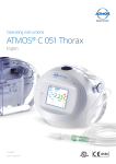
MA 41 Operating Instructions MAICO Diagnostics | 10393 West 70th Street | Eden Prairie, MN 55344, USA | Toll Free 888.941.4201 Operating Instructions MA 41 Table of Contents Page 1 Introduction ............................................................................................... 1 1.1 Intended Use Statement ......................................................................... 1 1.2 Essential Performance ............................................................................. 1 2 Description ................................................................................................. 2 3 Getting Started .......................................................................................... 3 3.1 Unpacking the Instrument ...................................................................... 3 3.2 Calibration of the Device ........................................................................ 4 3.3 Where to Setup...................................................................................... 4 3.4 Rear Panel Connections .......................................................................... 5 4. Working with the MA 41 ......................................................................... 6 4.1 Using the Control Panel of the MA 41 .................................................... 6 4.2 Functionality of Operating Elements ....................................................... 7 4.3 The Display of the MA 41 ....................................................................... 9 5 Measurement Methods of Audiometry.................................................. 10 5.1 Tone Audiometry ................................................................................. 10 5.2 Speech Audiometry .............................................................................. 17 5.3 Monitoring .......................................................................................... 22 5.4 Talk Forward ........................................................................................ 22 5.5 Documentation of the Results............................................................... 23 5.6 Patient Management ............................................................................ 24 6 Quick Reference Guide ............................................................................ 26 6.1 General Setup ...................................................................................... 26 6.2 Tone and Speech Audiometry ............................................................... 26 7 User Menu................................................................................................ 29 7.1 Setup Date and Time ............................................................................ 34 7.2 Set Printer Settings ............................................................................... 35 8 Cleaning and disinfection recommendations ......................................... 36 9 Device Update ......................................................................................... 37 10 Connection to the PC ............................................................................. 38 11 Regulatory Symbols .............................................................................. 40 12 Technical Data........................................................................................ 41 13 Warranty, Maintenance and After-Sales Service ................................. 46 D-0106002 i 8120525-2 Operating Instructions MA 41 14 Safety Regulations ................................................................................ 47 14.1 Electrical Safety .................................................................................. 47 14.2 Measuring Security ............................................................................. 47 14.3 Device Control ................................................................................... 47 14.4 Operation .......................................................................................... 47 14.5 Warnings and Statements .................................................................. 48 Appendix A: QuickSINTM Speech-in-Noise Test Manual ........................... 49 Appendix B: EMC Compatibility................................................................. 76 D-0106002 ii 8120525-2 Operating Instructions MA 41 1 Introduction Thank you for purchasing a quality product from MAICO Diagnostics. The Audiometer MA 41 is manufactured to meet all quality and safety requirements, and has been certified with the CE-symbol according to Medical Directive 93/42/EEC. In designing the MA 41 we placed particular importance on making it a userfriendly device, meaning its operation is simple and easy to understand. All functions of the MA 41 are software controlled, allowing for easy upgrades of new features and functions in the future. The user manual should make it as easy as possible for you to become familiar with the functions of the MA 41. If you have questions or ideas for further improvements, please contact us. Your MAICO Team 1.1 Intended Use Statement The MA 41 is a portable or standalone audiometer intended to be used for the identification of hearing loss and the factors that contribute to the occurrence of the hearing loss in the age range of children to adults. It is intended to be used by audiologists, ENTs, hearing healthcare professionals, or other trained technicians in a hospital, clinic, healthcare facility or other suitable quiet environment as defined in ANSI S3.1 or equivalent. 1.2 Essential Performance The following is considered essential performance: To generate and present stimulus signals in the audio range as specified in the applicable IEC 60645 series in normal condition Record and store a patient response D-0106002 1 8120525-2 Operating Instructions MA 41 2 Description The MA 41 is a portable one and half channel audiometer with pure tone, speech, and optional sound field audiometric testing. Additionally, it has limited special audiology test capabilities such as Stenger and Master Hearing Aid. It can be used as a portable audiometer or a desktop unit for ENT diagnostics, hearing aid fittings in the office, and for mobile audiometry. The MA 41 audiometer delivers 11 air conduction (AC) test frequencies from 125 Hz to 8 kHz, with levels from -10 dBHL to 120 dBHL. Bone conduction (BC) can be tested with 10 test frequencies from 250 Hz to 8 kHz with levels from -10 dBHL to 80 dBHL (using the B 71 bone conductor). As an upgrade option, the MA 41 is also capable of high frequency audiometry up to 16 kHz. The large back lighted LCD-color display shows level, frequency, transducer, signal type, audiograms, and other information for each channel. The MA 41 performs tests using DD 45 headphones, B 71 bone conduction oscillator, optional insert phones, and optional speakers. Built-in test signals include pure tone, pulse tone, warble tone, narrow band and speech noise. Inputs include ports for a live speech microphone and a CD player for speech test material. Speech tests can also be imported via a removable SD memory card. Outputs have separate jacks for air conduction headphones, bone conduction transducer, optional insert phones and optional sound field speakers. Optional transducers available include: TDH 39, insert phones, B 71W, B 81, HAD 200, HDA 300. Furthermore, the patient management feature provides the ability to store results in the device for further evaluation and documentation. Results can print directly via the USB printer or stored as a PDF file on the included SD memory card or USB flash drive. The MA 41 can be connected to the PC via USB to track the session and store the results in NOAH or the MAICO Database. In order to remain current with present and future technologies the MA 41 is compatible with PCs, easy to use, extremely reliable, and is adaptable to future developments. It is also designed to be easily serviced as the need arises. Automatic test programs make trouble shooting and the yearly calibration as effortless as possible. The speaker outputs can also be used as line level outputs for an external amplifier or active speaker. Please contact your authorized service center to change to line output levels. D-0106002 2 8120525-2 Operating Instructions MA 41 3 Getting Started 3.1 Unpacking the Instrument Prior to shipping, the MA 41 was carefully packed and inspected. However, it is good practice to thoroughly inspect the outside of the shipping box for signs of damage. If any damage is noted, please notify the carrier immediately. Please remove the MAICO instrument from the shipping box by lifting the case completely out of the box. The instrument can now be easily removed from the plastic packaging without the use of scissors or other sharp tools. SAVE ALL THE ORIGINAL PACKING MATERIAL AND THE SHIPPING CONTAINER SO THE INSTRUMENT CAN BE PROPERLY PACKED IF IT NEEDS TO BE RETURNED FOR SERVICE OR CALIBRATION. Notify the carrier immediately if any mechanical damage is noted. This will insure that a proper claim is made. Save all packing material so the claim adjuster can inspect it as well. Notify your dealer or MAICO when the adjuster has completed the inspection. Please check that all accessories listed below have been received in good condition. If any accessories are missing or damaged, immediately notify your dealer or MAICO. Standard Accessories: See page 43 for accessory listing. D-0106002 3 8120525-2 Operating Instructions MA 41 3.2 Calibration of the Device The instrument, headphones, bone conduction oscillator, as well as the optional insert phones and speakers, will come calibrated to the instrument and have the same serial number (e.g. 0021520). Use of transducers not calibrated to this particular instrument will likely lead to incorrect thresholds causing incorrect test results which will invalidate the test. If a transducer needs to be replaced, the instrument must be recalibrated with the new transducer. The use of non-calibrated audiometers can lead to incorrect measurements! 3.3 Where to Setup The MA 41 should be operated in a quiet room, so that the audiometric examinations are not influenced by outside noises. Ambient sound pressure levels in an audiometric test room shall not exceed the values specified in the norm ISO 8253-1:2010 or ANSI S3.1-1999. For use in noisier environments, headphones with optional sound insulation muffs are available. Electro-medical instruments, which emit strong electromagnetic fields (e.g. microwaves or radiotherapy devices), can influence the function of the audiometer. Therefore, it is not recommended to the use these instruments in close proximity to the audiometer as it may lead to incorrect test results. The test room must be at a normal temperature, usually from 15° C / 59° F to 35° C / 95° F, and the instrument should be switched on approximately 10 minutes before the first measurement. If the device has been cooled down (e.g. during transport), please wait until it has warmed to room temperature before using. Caution: External devices such as a computer, printer or Ethernet which are connected to the device must meet electrical safety requirements, such as IEC/EN 60601-1 or UL 60601-1. This is to avoid electrical shock to the user or the patient. D-0106002 4 8120525-2 Operating Instructions MA 41 3.4 Rear Panel Connections 1 2 3 4 5 6 7 8 9 10 11 12 13 14 15 16 17 Figure 1– Rear View of the MA 41 1: Power switch 2: Power socket 100-240VAC / 50-60Hz 3: Network socket 4: USB out socket 5: USB in socket 6: Patient response switch socket 7: Talk-back microphone socket 8: Mic live voice microphone socket 9: Monitor phone output socket 10: CD Input 11: Speaker left channel 12: Speaker right channel 13: Bone conduction receiver 14: Insert phone left channel 15: Insert phone right channel 16: Phone left channel 17: Phone right channel Place the MA 41 on a stable counter or table. Plug the power cord into the power socket on the rear panel. Connect all accessories with the appropriate sockets as shown above. Plug the power cord into a grounded outlet. Turn on the instrument with the power switch, which is located on the rear panel of the MA 41. The device will perform its initialization and boot up. Please wait until the test screen appears, this can take up to 60 seconds. If an error is detected the startup is stopped and a description of the error will be shown on the display. In this case please contact your local dealer for service. D-0106002 5 8120525-2 Operating Instructions MA 41 4. Working with the MA 41 The hearing level can be easily adjusted with the level dials on each side of the instrument (1). The instrument’s default setting is in 5 dB steps and can be adjusted to 2 dB or 1 dB steps, as needed. Figure 2 - Control Buttons The Stimulus Presenter buttons (2) and Store buttons located beside the (3)are left and right level control dials mode button you can change (8) With the STIM (1). from presenter to interrupter The corresponding LED mode. lights up when a with the Plus (4) and Minus (5) signal is presented. The frequency can be adjusted buttons on both sides of the instrument. The ergonomic design of the MA 41 makes it easy to control the dB level, signal presentation, and frequency adjustments with one hand. 4.1 Using the Control Panel of the MA 41 The main functions of the MA 41 are directly accessible by using the Function buttons which are located around the display. As the buttons have changing functionality, the actual function of each button is shown in the blue boxes on the screen above the button. To change the function of buttons (9), (11), (13) and (15), which have several functions, press the corresponding button and a list of alternative functions will appear. Quickly press and release the button until the desired function is selected. D-0106002 6 8120525-2 Operating Instructions MA 41 An extensive user menu for the customization of the MA 41 is available for advanced users (see chapter 7). 4.2 Functionality of Operating Elements The following table describes the main functions of each button for the tone and speech audiometry screens: Figure 3 - Control Panel MA 41 (1) (2) (3) (4) (5) (6) (7) Level control: adjusts level for the left/right the hearing ear STIM bar: presents or interrupts the signal for the left/right ear STORE button: stores results for the left/right ear Frequency up: change to higher frequency for tone audiometry, enters a correct answer for word recognition score (WRS) testing, or selects the next word in the word list for speech recognition threshold (SRT) testing with wave files Frequency down: change to lower frequency for tone audiometry, enters an incorrect answer for WRS testing, or selects a previous word in the word list for SRT testing with wave files Monitor with options to adjust monitor and talk back settings; for speech, the input calibration for microphone or CD player can be adjusted Function button: function is displayed on the screen based on test screen D-0106002 7 8120525-2 Operating Instructions MA 41 (8) (9) (10) (11) (12) (13) (14) (15) (16) (17) (18) (19) Tone: Select New, to delete all stored results and start a new session Speech: Reset the result percentage counter or Play wave file Channel STIM Mode button/TALK: to change from presenter to interrupter mode, or to talk to the patient by pressing and holding the button down Function button: to select left, right or both ears Transducer selector button: to choose between Phones, Insert, Bone and, Speaker (only calibrated transducers are available) Function button: function is displayed on the screen based on test screen Tone: No response, stores value with arrow below the symbol Speech: Select microphone, external CD player or wave file as signal source Test Signal selector button: Steady, Pulse, Warble, or P&W (pulse and warble tone) Function button: function is displayed on the screen based on test screen Tone: Selects test for selected receiver, either the pure tone threshold, Hearing Level (HL) or Uncomfortable Loudness (UCL); if Speaker is selected as the transducer an option for aided sound field threshold (Aided) is also made available Speech: Select Speech Recognition Threshold (SRT), Word Recognition Score (WRS), UCL or Master Hearing Aid (MHA). Select Unlock: Lock (locks the presentation of the signal in both channels), Track (activates the masking noise to automatically increase and decrease level in relationship to the signal), L&T (Lock and Track) Function button: function is displayed on the screen: Masking on/off, activates masking in the opposite ear Function button: to switch from tone to speech and back; the current function is displayed on the screen Function button - Menu: to enter the user menu, where settings can be adjusted, results can be printed out or stored as PDF on SD memory card or USB flash drive or the patient list can be entered SD memory card slot Level meter Note: When a Function button is grey, this identifies it as an inactive button with the current test set-up (ex. ). D-0106002 8 8120525-2 Operating Instructions MA 41 4.3 The Display of the MA 41 The instrument is set up by default to display the tone audiometry screen. Figure 4 - Start Screen Tone Audiometry Examples (Dual and Single Audiogram) The default frequency is set to 1 kHz and the level of the tone is set to 30 dBHL in the right ear, masking in the other ear is switched off. All channel information is shown on the display, as well as the type of the function buttons shown on the display. The display has an energy saving function; the backlight of the display is automatically dimed after approximately three minutes. Any action with the MA 41, such as pressing a button or rotating the dial, will immediately illuminate the backlight. D-0106002 9 8120525-2 Operating Instructions MA 41 5 Measurement Methods of Audiometry Remove any obstructions that will interfere with the earphone cushion placement over the ear (e.g. hats, eyeglasses). Always use the headphones with appropriate padded ear cushions. Ensure the headphones are placed correctly over the patient’s ears and that the red is over the right ear and the blue is over the left ear. Adjust the headband of the headphones so that the receivers are at the correct height (the sound output grid on the inside of the headphone should be directly over the ear canal). Ask the patient to press the button on the patient response switch when the tone is heard, even if it is barely audible. For hygienic reasons it is important to disinfect the ear cushions on the headphone between patients (see chapter 8). 5.1 Tone Audiometry The MA 41 supports tone audiometric testing methods. The following testing methods can be started in the tone audiometry mode and the results can be saved to the instrument. D-0106002 Air conduction testing Bone conduction testing Sound field testing Pure tone hearing threshold Uncomfortable Loudness (UCL) Aided sound field thresholds (Aided) 10 8120525-2 Operating Instructions MA 41 5.1.1 Pure Tone Testing During pure tone audiometry, the patient’s hearing threshold is measured. Typically the threshold search begins with air conduction testing in the ear with better hearing. While viewing the tone screen the following settings will be displayed. Figure 5 - Pure Tone Audiometry Screen Example The default setting is the right channel set to air conduction pure tone and the left channel is switched off. The frequency is automatically set at 1,000 Hz. The audiometer provides one and a half channels, one for the test signal, and the other for the masking signal. The test signal can be routed to the left, right, or both ears. If masking is on, the masking signal is routed to the non-test ear, through the primary transducer established in the set-up menu. Select the ear to be tested by pressing the function button (9) on the control panel underneath the screen. Press several times to toggle between Right, Left and Both. Next, select the transducer to be used, headphones (Phones), insert phones (Insert), bone conductor (Bone), or sound field speaker (Speaker) by pressing the appropriate button (10). Press the button several times until the LED indicates the required transducer. Only calibrated transducers are available. The level and frequency is displayed as a numerical value at the top of the screen and is also indicated by the cursor within the audiogram. The dBHL can be changed with the attenuator dials on both sides (1) of the instrument. Use the frequency plus (4) or minus (5) keys to increase or decrease the frequency. Press the STIM button (the blue button touching the attenuator dials) to present D-0106002 11 8120525-2 Operating Instructions MA 41 or interrupt the tone. The status LED for the stimulus mode button (8) will illuminate when the tone is presented. Follow your preferred procedure for the hearing threshold evaluation. Note: A warning prompt appears on the display in the event that the hearing level exceeds 100 dBHL. The warning prompt disappears after approximately 3 seconds. As long as the prompt is visible on the display, no further entries can be made. Test the frequencies: Starting at 1,000 Hz, test the higher frequencies first, then the lower frequencies. Use the frequency up key (4) to select the next higher frequency and use the frequency down key (5) to select the next lower frequency. Once a threshold value is established at the desired frequency, press the store button (3) to store the threshold. The appropriate symbol will be plotted in the audiogram on the display. Once all frequencies are tested, select the other ear and repeat the hearing threshold test. Pulse Tone If required, the test can also be performed with a pulsed tone. Set the test signal button (12) on PULSE and the pure tone will be switched to a pulsating tone. Warble Tone If required, the test can also be performed with a warble (frequency modulated) tone. Press the test signal button (12) and the pure tone will frequency modulate. The warble tone can also be pulsed as described above. D-0106002 12 8120525-2 Operating Instructions MA 41 5.1.1.1 Masking Masking is required if there is a notable threshold difference between the left and right ears. It is possible for sound to be transmitted to both ears via bone conduction while testing the poorer ear. This is called “crossover.” Crossover occurs often while testing bone conduction, but it can also occur during air conduction testing. Relevant to crossover is the sound level received by the opposite ear. The difference between the original test signal in the test ear and the received signal in the opposite ear is called “interaural attenuation.” For bone conduction measurements the interaural attenuation is 0 to 15 dB. Bone conduction crossover is therefore possible even with a slight difference in hearing loss between ears. To ensure that the patient will not experience crossover, mask the opposite ear. Masking increases the hearing threshold of the opposite ear. For bone conduction the masking signal is automatically routed to the opposite output of the phones or inserts. The masking is done with a noise signal which is transmitted by the headphone. For pure tone audiometry a narrowband noise is used. This noise changes its center frequency according to the frequency of the test signal. Note: Masking is only available in when Right or Left ear is selected. When Both is selected, the Masking Off key is greyed out (i.e. ). D-0106002 13 8120525-2 Operating Instructions MA 41 Manual Masking The masking is switched on by pressing the Masking On/Off button (15). The channel of the non-test ear is switched on and set to noise with a level of 0 dBHL. Figure 6 - Tone Audiometry with Masking Adjust the level of the masking noise by the right-hand level control dial. If the Store button on either side of the instrument is pressed, the hearing threshold value will be stored in the audiogram with the corresponding masking symbol. The masking sound should be continuously presented for effective masking by pressing the STIM button. You can interrupt the masking signal by pressing the corresponding stimulus button (2). Automatic Masking With the manual masking, as described before, the masking level should be adjusted every time you change the test signal level. The MA 41 has a tracking function for easy masking. Set the tone level and the masking level to a desired difference for effective masking. Press the TRACK button (14) to implement the automatic masking feature. The masking level is automatically changed if you adjust the test signal level (e.g. if the test level is at 30 dBHL and the masking level 50 dBHL and you change the test level to 45 dBHL the masking level will automatically adjust to 65 dBHL). D-0106002 14 8120525-2 Operating Instructions MA 41 5.1.2 Bone Conduction Testing Place the bone conduction oscillator so that the flat, circular side of the transducer is placed on the mastoid, at the noticeable ledge of the cranial bone behind but not touching the pinna. The other side of the headband is placed in front of the opposite ear. Set the receiver selector to Bone and select the testing ear. Perform the test utilizing the same method as air conduction testing. For hygienic reasons it is important to disinfect the bone conduction oscillator following each patient (see chapter 8). 5.1.3 Sound Field Testing (optional) Set the transducer selector (10) to Speaker. Perform the test utilizing the same method as air conduction testing. Warble tones should be used in the sound field as pure tones may provide inaccurate results in the typical test room. Perform the test in the same way as described in the air conduction section above. 5.1.4 Uncomfortable Loudness (UCL) Testing Testing of UCL can be measured using pure tone or speech stimuli. The purpose is to determine the dBHL level at which the stimuli becomes uncomfortable to the patient. The UCL is described as the level between very loud and too loud as perceived by the patient when listening to the test signal. This information is valuable for determining the limits of a patient's dynamic range. Warning! Because this test uses high sound pressure levels, it is extremely important to perform this test using the utmost caution to avoid causing hearing loss. To prevent the possibility of extreme discomfort by the patient, it is important to start the test at a comfortable level. Press and release the test mode selector key (13) below the display to select UCL. The LCD-display in the bottom row changes from HL to UCL. Start with a test level of 60 dBHL and present the tone briefly (max. 1s). If the signal was recognized by the patient as “not uncomfortable,” increase the level and proceed as described before. If the signal was uncomfortable for the patient store the value. Proceed accordingly with other test frequencies. D-0106002 15 8120525-2 Operating Instructions MA 41 5.1.5 Stenger The Stenger test is a test to confirm the presence of pseudohypacusis. During this test, two tones of the same frequency will be presented simultaneously to both ears, and only the louder tone will be perceived. Select HL to perform the Stenger test and select both ears (9). Instruct the patient to press the response button when the tone is heard. Present a tone to the better hearing ear 10 dB above threshold and wait for the patient to indicate the tone has been heard. Now present the tone to the poorer ear 10 dB below the indicated threshold (the patient may “ignore” this tone). Present the tones simultaneously by pressing the lock function button (14) and the STIM Mode button (8) to set it to interrupter mode. If the patient responds it is a negative. If the patient does not respond it is a positive Stenger, indicating that the tone is heard in the poorer ear and the patient is ignoring the stimulus. D-0106002 16 8120525-2 Operating Instructions MA 41 5.2 Speech Audiometry The MA 41 supports speech audiometry. To conduct speech tests using speech test material you can use a CD player, wave files from the SD memory card, or a microphone. Caution: If you are using a CD player powered by electrical current, the player must meet electrical safety requirements, such as IEC 60601-1 or UL. This is to avoid electrical shock of either the patient or you. If you are not sure if your player meets these requirements it is safer to use battery power. 5.2.1 Input Calibration The MA 41 must be calibrated to the particular speech test to ensure valid test levels. That means every time you change the speech test CD you must recalibrate the instrument. To calibrate the CD speech input, select CD with the signal selector key (11). Press the Monitor button (6) and then InCal (17) and the calibration screen appears (see figure 7b). Figure 7a – Monitor Settings Figure 7b – Input Calibration On every CD with speech test material there is a reference signal, such as a reference tone or speech simulating noise. Play back the reference signal with the CD. Use the left or right level control (1) and adjust the levels until the VU-meter (19) shows all yellow lights and one green light. If one or more red lights are on, reduce the level using the level control dial (1). To calibrate the microphone for live voice testing, select MIC with the signal selector key (11). Press the Monitor button (6) and then InCal (17) and the calibration screen appears. Use the left or right level control (1) and adjust the levels until the VU-meter (19) shows all yellow lights and one green light. Store the calibration and leave the calibration mode by pressing the OK button on the left side of the display. D-0106002 17 8120525-2 Operating Instructions MA 41 5.2.2 Performing Speech Testing Use the function button for Speech on the right side of the tone screen (16) to switch to speech testing. The speech test screen will open, and the unit will default to the right ear and the level will be set to the default value. The speech recognition threshold (SRT) is a test indicating the lowest level in which speech is understood using a closed set of spondaic words. Speech testing can be done via recorded speech test material from CD or wave files or with the microphone and live voice using standardized word lists. Ask the patient to repeat each word. Often times a carrier phrase such as, “Say the word _______” may be used. The patient should sit at a distance of at least 1 meter from the device. Additionally, any obstructions which may interfere with the placement of the earphone cushions on the ear (i.e. hair, eyeglasses) should be removed. Ensure the headphones are put on correctly. Adjust the headband of the headphones so that the receivers are at the correct height (the sound output grid should be placed directly over the ear canal). Select the ear to be tested by pressing Right, Left, or Both by the function button (9) on the control panel underneath the screen. Figure 8 - Speech Test Screen Next, select the transducer to be used, Phones, Insert, or Speaker by pressing the Transducer button (10). Toggle to the required signal by the selector button (11) to MIC/CD/Wave. D-0106002 18 8120525-2 Operating Instructions MA 41 5.2.3 Speech Audiometry with Microphone or CD player Connect the microphone or CD player to the corresponding input (10). Select the test ear (9) and MIC or CD as signal source by the function button (11). Make sure that the input signal is calibrated correctly, as described above. Select the test SRT, WRS or UCL with the function button (13). For the SRT test familiarize the patient with a closed set of spondaic words at a level loud enough for them to hear and understand. Begin the test and decrease the level as the patient repeats the word. Once the threshold has been found press the Store button (3) to save the result. For the WRS test, the level remains fixed and correct or incorrect answers can be entered by the Frequency Plus (4) and Frequency Minus (5) button. Once the word list has been completed by the patient, press the Store button to save the established WRS score. To clear the word counter, press the Reset key (6) on the left side of the display. If no counter is set the Reset key (6) is displayed grey. For the UCL testing the level is increased until the patient indicates the level is uncomfortable and the result can be saved by pressing the Store button (3). 5.2.4 Speech Audiometry with Wave Files If Wave is selected by the speech signal selector (11) a menu will pop-up with the available word lists, stored on the SD memory card. A word list can be selected by using the level controls (1) to scroll through the list. A list can be loaded by pressing the Stimulus button (2). The word list will then be displayed on the speech audiometry screen. The level is displayed as a numerical value at the top of the screen. The level can be changed with the level controls (1) on both sides of the instrument. Before starting the playback of the wave files, the first word can be selected by the Frequency Up and Down buttons (4) and (5). Press the function button Play (7) to start. Once the speech test is started the test can only be stopped by pressing the Cancel (16) or Store (3). The procedure for the SRT, WRS and UCL test is the same as the procedure for CD or microphone testing. For the SRT test, a word needs to be selected in the wordlist by the frequency up (4) or down (5) key. When the Play button (7) is pressed, the selected word is presented. D-0106002 19 8120525-2 Operating Instructions MA 41 For the WRS test score, tally the correct words by pressing the frequency up (4) key and the incorrect words by pressing the frequency down (5) key. The next word will be played back automatically. The correct word is displayed green, while incorrect word is displayed red. By pressing Repeat (7), the word will be repeated. Once a wave file has been selected, the intensity cannot be changed. Select the presentation level before selecting Play (7). Figure 9 – Speech Audiometry with Wave Files The percentage of the speech discrimination score will be displayed and stored in the speech table or audiogram as soon as the Store button (3) is pressed. Press the function button List (6) to load another word list. UCL measurements are best performed with the Passage wave file include with the device. Select the ear for testing (9). Press the function button Play (7) to start the presentation to the patient. Rotate the attenuator wheel (1) to increase the volume until the patient reports this is uncomfortable loud. Press Store (3) to save the results. 5.2.5 Masking Speech audiometry masking can be used in the same manner as described in chapter 5.1.1.1 for pure tone audiometry. Instead of narrowband noise, speech noise (SN) is applied when masking is turned on. Masking noise is activated in the non-test ear by pressing the function button Masking On/Off (15). Adjust the level of the masking channel by the corresponding level control (1) for effective masking. D-0106002 20 8120525-2 Operating Instructions MA 41 5.2.6 Master Hearing Aid (MHA) The Master Hearing Aid (MHA) feature utilizes input signals from the Live Voice (Mic), external CD/MP3 player or with the wave files. These signals are then filtered by various high pass filters to simulate a hearing aid. Begin by selecting a signal source in the speech mode with the function button (11). Start the MHA function by pressing the Test Selection button (13). When using wave files begin testing by pressing the Play button (7) to play back the imbedded wave files. Press the stimulus mode (8) indicator to alternate between signal sources like the microphone or the CD. Change the dB presentation levels with the level control dials (1), and control the filtering options by using the frequency Up (4) and Down (5) keys. Figure 10 - Display Master Hearing Aid D-0106002 21 8120525-2 Operating Instructions MA 41 5.3 Monitoring All signals presented to the patient can be monitored by the examiner via a monitoring headset or the internal speakers. For this purpose, press the Monitor button (6) and the monitor screen will appear. Enable monitoring by pressing the function button Monitor On/Off (9). Monitoring by the integrated speaker is switched on by pressing the button (13) and the external headset is activated for monitoring via button (11). Then the monitor level of the left and right channel can be adjusted with the corresponding level control dial (1). In order to hear the signal given to the patient, make sure to activate monitoring (9). Figure 11 - Display Monitor Settings The talk back microphone is activated by the button (15) and its level adjusted by the frequency up and down buttons (4), (5). 5.4 Talk Forward Connect the microphone headset (or optional gooseneck microphone) to the microphone socket (8) on the rear side of the device. To talk to the patient press and hold the STIM mode/TALK button and speak into the microphone. Adjust the level by turning the left or right level control (1) while the STIM mode/TALK button is pressed and held. D-0106002 22 8120525-2 Operating Instructions MA 41 5.5 Documentation of the Results All stored results can be directly printed via the USB printer. Make sure that a compatible printer is connected via the USB port (4) and the device is configured according to the connected printer settings; refer to menu settings in chapter 7.2. The results can also be stored as a PDF file on a SD memory card or USB flash drive to be later transferred to a PC for further usage. The PDF file contains the measurement results. An SD memory card needs to be inserted in the SD card slot (20) or a USB flash drive connected to the USB socket (4) on the rear side of the device. When the examination has been completed, press the Menu button (17) in the tone or speech test mode. The user menu is opened and the functionality of the function buttons (11), (13) and (15) changes to PDF, Print, and Patients, respectively. To printout the results press the Print button (13). Make sure that a compatible printer is connected and the printer settings are correct. To store the results on the SD memory card or USB flash drive, press the PDF button (11). A PDF will be created and stored on for further transfer to a PC or printout via a PC connected printer. Make sure that a SD memory card is inserted in the SD memory card slot (18). After printing or creating a PDF you will automatically return to the tone or speech test mode. Enter the patient list by pressing the Patient button (15) to store the results. D-0106002 23 8120525-2 Operating Instructions MA 41 5.6 Patient Management The patient management option allows the results of the audiological tests to be stored on the SD memory card. The results can be reloaded at a later time to be reviewed, edited, or printed. Patients can be stored by a number ID or by entering the name and birth date. The demographic patient information can be entered using the level controls (1) or a connected USB keyboard. Enter the User Menu by pressing the Menu button (17) in the tone or speech audiometry screen. Press the button Patients (15) to display the patient list. To comply with patient privacy laws the option to add a PIN code for entry to this list has been offered. To activate this feature press the New Patient button (15) followed by the Login button (15). Enter the desired 4 digit PIN using the level control dials (1) and the Stim button (2). Once the 4 digits have been entered press the Set button (9) and the device will return to the patient list. Moving forward the PIN will be required to enter the patient list. To deactivate the PIN, select Login Off after following the same steps as listed above. Figure 12 – Patient List Select a patient using the level controls and press the Stimulus button (2) to display the stored sessions. Select a session and press the PDF button (11) to save the PDF on the SD memory card or USB flash drive. To print the results to a connected printer press Print (13). The patient information will only be included on the printout if it is done in the patient list, or if the PDF is created in the patient list screen. Current results can be stored to a numbered patient or to a named patient. Entering the Patient List, automatically a new numbered patient with a new D-0106002 24 8120525-2 Operating Instructions MA 41 number will be selected. Just press the Save button (9) to save the current session to the new patient number. To save the results to an existing patient, select a patient by the level controls and press the Save button. To save the current results to a new patient with a new patient name, press the button New Patient (15) and a screen appears to enter the patients last name, first name, ID and date of birth. Figure 13 – New Patient Enter the characters of the name by scrolling through the alphabet with the level controls and enter the selected character by using the Stimulus button (2). Jump to the next or previous field by using the Frequency Up (4) or Down (5) button. The date can be entered in the same manner with the level controls. Delete the last character or number by pressing the Delete button (17). A USB keyboard can also be utilized to enter the patient information. Connect it to the USB connector (4) and type in the characters. Jump to the next field with the tab key. Press the function button OK (6) to save the new patient and go back to the patient list. The new patient is selected and the current measurement results can be saved to this new patient by pressing the function button Save (9). Press the button No Name (9) to store the results only by a patient number, without entering a name or use Cancel (6) to go back to the Patient List without saving. D-0106002 25 8120525-2 Operating Instructions MA 41 6 Quick Reference Guide 6.1 General Setup 6.1.1 Startup Settings Air conduction Pure tone on the right channel, left channel is switched off 30 dBHL tone Presenter mode 6.1.2 Transducer Selection Select the transducer to be used, headphones (Phones) or insert phones (Insert), by pressing the appropriate button (10). The display shows the selected transducer at the top of the display screen below the presentation levels. 6.1.3 Signal Selection For tone testing the test signal is always tone. For speech audiometry the signal can be selected by the SIGNAL key (11). The type of NOISE signal is dependent upon the opposite channel’s signal. 6.1.4 Masking Use the Masking On/Off button (15) to activate masking in the non test ear. For tone audiometry narrow band noise is used as the masking signal and for speech audiometry, speech noise is used. 6.2 Tone and Speech Audiometry 6.2.1 How to Select Tone or Speech Audiometry Mode There are two audiometry modes. Tone audiometry: shows level and frequency on the display Speech audiometry: shows level, correct and incorrect words, and speech discrimination percentage on the display Use the MODE button (16) to switch between tone and speech mode. D-0106002 26 8120525-2 Operating Instructions MA 41 6.2.2 Tone Audiometry Frequency Selection Use one of the two sets of frequency keys (4) or (5) to select the frequency. The maximum and minimum frequency depends on the transducer you have selected. Warble Tone Press the Test Signal button (12) to activate the warble tone. The LED will highlight Warble. Pulse Tone Press the Test Signal button (12) to activate the pulse tone. The LED will highlight Pulse. Tracking Function Press the TRACK key (14) to activate tracking. Both channels will adjust when only one attenuator is adjusted. Lock Function Press the LOCK/UNLOCK (14) key to activate the interlock function. Signals from both channels will be presented simultaneously with the press of only one STIM button (2). If both ears are selected, LOCK is automatically activated. Select L&T (14) to interlock the stimulus presentation of both channels as well as the tracking of the levels. STIM Mode Selection Press STIM MODE (8) key to switch between continuous presentation and presentation by pressing the STIM button (2). When in continuous presentation mode the STIM buttons function as interrupters. The light above the STIM MODE key is on if continuous presentation is selected. CD and Wave speech signals are always in continuous presentation. Talk Forward Microphone Press and hold the STIM MODE (8) to activate Talk Forward. Adjust the level by turning one of the attenuator dials (1) while in the mode. Talkback Microphone and Monitor Volume Control Press the Monitor key on the left side of the display and the volume control bars for talkback and monitor are shown. Adjust the monitor volume with the right and left dials (1). Adjust the talkback microphone volume with the plus/minus keys (4) or (5). To store the actual settings press OK (19). D-0106002 27 8120525-2 Operating Instructions MA 41 6.2.3 Speech Audiometry To select speech audiometry, select Speech (16) and the test SRT or WRS (13). Use the frequency up (4) and down (5) key to select a word in the word list. For the WRS test the display shows the percentage of correctly repeated words. To count the word as correct press the frequency key (4) up. To count the word as incorrect press the frequency key (5) down. To clear the counter, press the Reset key (7) on the left side of the display. Speech Calibration To calibrate the MIC or CD speech input, select the input with the SIGNAL selector key (11). Press the Monitor button (6), so that the monitor setting screen appears. Now press the InCal button (17) on the right side of the display and the calibration screen appears. Play the reference signal with the CD player or speak into the microphone. Use the left or right intensity dial (1) and adjust the levels until both VU-meters show all yellow and one green light. If one or more red lights are displayed, reduce the level using the corresponding dial (1). Store the calibration and leave the calibration mode by pressing the OK (6) button on the left side of the display. 6.2.4 Documentation of the Results Printout Enter the user Menu by pressing the function button (17) and press the Print (13) button to printout the results. Store Results as a PDF Enter the user Menu by pressing the function button (17) and press the button PDF (13) to save the results as PDF file on SD memory card or USB flash drive. Store the Result in the Patient List Enter the User Menu by pressing the function button (17) and press the button Patient (15) to enter the patient list. Enter a new patient by pressing the button New Patient (15). It is also possible to print a result from the patient list or to create a PDF of the result. Select a stored session of a patient in the patient list and press then the button PDF (11) or Print (13). In this case, the patient information will be included in the PDF or printout. Press the button New (7) in the patient list to start a new session. D-0106002 28 8120525-2 Operating Instructions MA 41 7 User Menu The User Menu enables the user to customize the device to meet their specific needs. Additionally, the menu allows the user to printout the results via USB printer, store the results as a PDF on an SD memory card or USB flash drive, and the ability to enter the patient list. To enter the User Menu press the Menu button (17) on the right side of the display. Figure 14 - User Menu Screen To choose an item from the menu use the level control dials. A short description of the selected setting item will be displayed below the user menu list. To display the sub items or change the setting of the selected item press the STIM Presenter button (2). To confirm the change press the OK button (7) on the left side of the display, or press Cancel (6) to return without any change. Note: When changes have been made to the menu and saved, restart the device to confirm all changes are implemented. D-0106002 29 8120525-2 Operating Instructions MA 41 These menu items are available (Bold represents default setting): Frequency Settings Frequency Default Frequency Set (On/Off): Set default frequency if side, transducer or signal type has changed Back: Frequency control jumps to 1,000 Hz if the highest and lowest frequency was reached Stop: Frequency control function stops at highest and lowest frequency Wrap: Jumps to the lowest/highest frequency when the highest/lowest frequency Select/deselect Frequency Roll Standard Frequencies Level Default Level Level Steps Inverse Dialing Speech Level Unit D-0106002 30 On/Off: Set default level after changing signal type 5; 2; 1 Change effect on dialing an encoder: Dial Down dBSPL/dBHL: Select the level unit for speech signals 8120525-2 Operating Instructions MA 41 Signal Controller Assignment Presenter Duration Interrupter / Presenter Mode Pulse PTA CD Channel D-0106002 Select the CD Channel 31 Assign ear side fixed to the left or right controller; - Same, left dial controls level of the left ear, right dial the level of the right ear - Interchanged, left and right dial controls the level of the opposite ear Assign signals fixed to the left and right controller - Test signal always on the left hand side or always on the right hand side This setting requires a restart Unlimited, signal is presented as long as the STIM bar is pressed 1.5 Seconds, signal is switched off after 1.5 seconds User defined duration, user can define a maximum presentation duration Default Presenter or Interrupter Mode 500 ms, slow pulsing 250 ms, fast pulsing Select/deselect frequencies for the calculation of the PTA value for the default transducer Both/Channel A/Channel B 8120525-2 Operating Instructions MA 41 Store Properties Change Frequency After Store Change Level After Store Monitoring Selection of Default Transducer Monitoring Tests Start Test Printer Settings Set Printer Settings PDF Save Option Save on SD Card Default Transducer Save on USB Device Information Date/Time Show Information Set Date/Time Display Brightness Language D-0106002 32 Moves to next test frequency after storing a threshold (on) or stays on same frequency after storing (off) Change in level after storing a threshold (stay at the same test level (0) or decrease by 10, 20, or 30 dB) Headphones or Inserts Monitor only speech signals (off) or all signals (on) Tone/Speech, defines test which will load after start-up Opens a dialog to select a printer and configure its settings Stores PDF files to an SD memory card Stores PDF files to a USB flash drive Shows device information Opens a dialog to change the date, time, and the date format to US or International Change the display brightness from 1 – 100%, store new value by pressing the Store button (3) English/German/Italian/ French/Spanish, etc. 8120525-2 Operating Instructions MA 41 Diagram Settings Diagram in Speech Test Diagram or Table Number of Diagrams in Tone Test No audiogram, only the level and frequency, one combined audiogram or two separate audiograms for left and right On/Off, displays a dotted line, connecting the bone conduction results Int Symbols/US Symbols/ UK Symbols Export User Settings to SD Card/Import User Settings from SD Card. Bone Lines Bone Symbol Setting Import/Export User Settings D-0106002 33 8120525-2 Operating Instructions MA 41 7.1 Setup Date and Time Select Date/Time in the user menu by scrolling down with the left or right level control (1) and select Set Date/Time by using the stimulus presenter bar. The following screen will appear: Figure 15 - Date and Time Settings Set the date format to International or US by the function button (9). Jump to the required position of the date or the time by the left Frequency Up/Down button (4) or (5) and change the value by the right Frequency Up/Down button (4) or (5) or left level control. Press the function button OK (6) to store the changes or Exit (7) to leave the Date/Time setting screen without saving the changes. D-0106002 34 8120525-2 Operating Instructions MA 41 7.2 Set Printer Settings Select the printer by turning the left or right level control (1) down. The color mode is automatically adjusted. If the color mode is wrong adjust the color mode as well. Jump to the field paper format by pressing the stimulus presenter bar several times and select A4 or Letter format by using the level controls. If the printer is connected to your Ethernet network select Ethernet as port. Additionally, the IP address of the printer needs to be entered in the field “IP Address.” Select the number of the IP address by rotating the level controls and press the STORE button to enter the selected number. Save the settings and return to the user menu by pressing the function button OK (7). Figure 16 - Printer Settings Test your printer settings by a sample print before starting the audiological assessment. Incorrect settings may require a restart of the device. Enter the field clinic name by using the STIM button. Select letters by rotating the level control and enter the selected letter by pressing the STORE button (3). Save the settings and return to the user menu by pressing the function button OK (7). D-0106002 35 8120525-2 Operating Instructions MA 41 8 Cleaning and disinfection recommendations It is recommended that parts (device and accessories like headphones, ear cushions) which come in direct contact with the patient be subjected to standard cleaning and disinfecting procedure between patients. Please disinfect the instrument and its accessories in dependence on the specific existing infection potential. Recommendations for cleaning and disinfection of MAICO device presented in this document are not intended to replace or contradict policies in effect or procedures required for infection control at the facility. If there is not a high infection potential, MAICO recommends: Before cleaning always switch off and disconnect the device from power supply. For cleaning use a lightly dampened cloth with soap water solution Disinfect the instrument and its accessories by wiping the surfaces with wet SaniCloth® Active wipes or a comparable product and allow them to take effect for the duration related to the specific disinfection aim listed in product data sheet of the disinfection product. Please follow also its instructions for cleaning. Wipe before and after each patient After contamination After infectious patients Disinfect computer, keyboard, transport trolley etc. with Sani-Cloth® Active wipes: once a week after contamination when polluted To avoid damage of the device and its accessories, please mind the following: Do not autoclave or sterilize. Do not use the device in the presence of fluid that can come into contact with any of the electronic components or wiring. Should the user suspect fluids have contacted the system components or accessories, the unit should not be used until deemed safe by a MAICO certified service technician. D-0106002 36 8120525-2 Operating Instructions MA 41 9 Device Update Insert the SD memory card into your computer and copy the update file MaicoMA4xseries.CAB to the SD memory card. Switch off the MA 41, insert the SD memory card into the MA 41, and then switch the device on. The update will be installed automatically. Wait until the update is finished and follow the instructions. Remove the SD memory card from the MA 41, it will boot up normally. Following the update, please use your computer to delete the update file from the SD memory card in order to have normal use of the card. D-0106002 37 8120525-2 Operating Instructions MA 41 10 Connection to the PC Install the included software on your PC. This will allow you to use your device with NOAH™ and the MAICO Database. The driver for the device will be installed automatically. Connect the MA 41 by USB cable to the PC and turn on the device. The required driver will be installed. Please follow the installation procedure. When the installation program asks you how to search for software, choose “Yes, this time only” and click on the Next button. Figure 17 - Installation Advice Select automatic installation in the next dialog window and click the Next button. Wait till the MAICO MA4x family driver is installed and the operating system updated. Click on the Finish button when the installation of the driver is completed. The new hardware is now ready to use. Figure 18 - Software Installation D-0106002 38 8120525-2 Operating Instructions MA 41 Once the instrument is linked to the PC audiometry software, you are able to record the results while performing your audiological assessment. Make sure that the software is running and that a connection is built up before starting a new session. Review the Audiometry Module User Manual for complete instructions of software use. This is located on the included CD and USB. D-0106002 39 8120525-2 Operating Instructions MA 41 11 Regulatory Symbols Symbol REF IEC Pub. Description 980 & 60601-1 Serial Number 980 & 60601-1 Date of Manufacture 980 & 60601-1 Manufacturer 980 & 60601-1 Caution, Consult Accompanying Documents 980 & 60601-1 Return to Authorized Representative, Special Disposal Required 980 & 60601-1 Reference Number 60601-1 B Patient Applied Part According to IEC60601-1 980 & 60601-1 Consult Operating Instructions 60601-1 Keep Dry 60601-1 Transport and Storage Temperature range Logo 980 & 60601-1 4005727 D-0106002 Medical Equipment Classified by Intertek Testing Services NA Inc. with respect to electric shock, fire, and mechanical hazards only, in accordance with UL 60601-1. Classified under the Medical Device Directive (93/42/EEC) as a Class IIa device. 40 EU Authorized Representative Registration Label 8120525-2 Operating Instructions MA 41 12 Technical Data EU Authorized Representative: EC REP Standards: Test Frequencies: Level Step: Maximum Sound Pressure Level: AC with earphone DD 45: MAICO Sickingenstr. 70-71 D-10553 Berlin Germany ANSI S3.6, ANSI S3.43, IEC 60645-1, IEC 60645-2, ISO 389 UL 60601-1 American Standards for Medical Electrical Equipment IEC/EN 60601-1 International Standards for Medical Electrical Equipment CSA C22.2 # 601-1-M90 Medical Device Directive (MDD) to comply with “EC Directive” 93/42/EEC 125 Hz – 8,000 Hz 9,000 Hz – 16,000 Hz (upgrade) 5 dB, 2 dB or 1 dB level steps (user selectable) - 10 dBHL to 120 dBHL BC with B 71/B 71W Bone Conduction Oscillator: - 10 dBHL to 80 dBHL Insert earphones Ear 3A: - 10 dBHL ... 120 dBHL Sound field speaker from Amp: Tones: Speech: - 10 dBHL ... 100 dBHL - 10 dBHL ... 90 dBHL D-0106002 41 8120525-2 Operating Instructions MA 41 Sound field speaker from MA 41: (using SP90 Speaker Kit): Tones: Speech: - 10 dBHL ... 90 dBHL - 10 dBHL ... 70 dBHL Test Signal: Pure tone, Pulse tone, Warble tone Masking Signals: Narrow Band Noise: 5/12 Octave filter with the same center frequency resolution as pure tone Speech Noise: 125 to 6,000 Hz falling 12 dB/octave above 1 kHz (+/-5 dB) Modulation: Pulse Tone: Warble Tone: 0.25/0.5 s on time 5% sinus frequency modulation, repetition rate 5 Hz Tests: Tone: Speech: HL, UCL SRT, WRS, UCL Patient Response: Handheld response switch Monitor: Build in monitor speaker, headset Communication: Talk forward and talk back Data Connection: USB, LAN Ethernet D-0106002 42 8120525-2 Operating Instructions MA 41 External Devices: USB keyboard CD player Supported USB printers: HP (PCL 3 and PCL 5e) Epson (ESC/P2, LQ, Stylus Color) Canon (iP100, iP90, BubbleJet) Stimulus Functions: Tone Presenter / Interrupter Interlock (tone presentation of both channels simultaneously) Tracking (fixed level difference between both channels) Masking Warm-up Time: Less than 10 min after power on Mode of Operation: Continuous Environment Conditions: 15 - 35 ̊C / 59 - 95 ̊F (operation) 5 - 50 ̊C / 41 - 122 ̊F (transport) Humidity: 30-90% Dimensions: Weight: Power Supply: Power Consumption: Device Fuses: D-0106002 W x D x H: 34.5 x 20 x 8 cm / 13.4” x 7.9” x 3.2” 1.5 kg / 2.7 lbs 100 - 240 V~ 50/60 Hz ±10 % Approximately 60 VA 2 x 1A slow blow 43 8120525-2 Operating Instructions MA 41 1 2 3 4 5 6 7 8 9 10 11 12 13 14 15 16 17 Figure 19 – Connection Sockets of the MA 41 Connection sockets: Specification: 1: On/Off 2: Power Power (100 ... 240 V~ 50/60 Hz) Ethernet USB 2.0 USB 2.0 RI= 500 ZI= 1 k, UI= 0.38 - 500 mVeff ZI= 1 k, UI= 0.38 - 500 mVeff ZA= 250 , UA= 8 Veff ZI= 47 k, UI= 0.04 - 5 Veff 3: Network 4: USB out 5: USB in 6: Patient response switch 7: Talk Back Microphone 8: Mic Microphone 9: Monitor phone 10: CD Input ZA= 4 , UA= 8 Veff ZA= 4 , UA= 8 Veff ZA= 4 , UA= 8 Veff ZA=10 , UA=1 Veff ZA=10 , UA=1 Veff ZA=10 , UA=1 Veff ZA=10 , UA=1 Veff 11: Speaker left 12: Speaker right 13: Bone (bone conductor) 14: Insert phone left 15: Insert phone right 16: Phone left (headphone) 17: Phone right (headphone) D-0106002 44 8120525-2 Operating Instructions MA 41 Standard Accessories: Items Part Number DD45 Headphones B71 Bone Conductor Patient Response Switch Power Cable Mic/Monitor Headset Adaptor, Stereo, 1/8” to 1/4” SD Memory Card w/ Wave Files (2 GB) CD, Noah Module and Maico DB USB Flash Drive 1 Meter USB Cable Carrying Case MA 41 Manual MA 41 Quick Guide 8010880 8010800 8011091 8011392 8010870 8010402 8100885 8105958 8102480 8004381 8100797 8120525 8102407 Optional Accessories: Items High Frequency Option (HDA200 and High Tone License) EAR 3A Insert Phones TDH 39 Headphones Monitor Phone Talk-Back Microphone Gooseneck Microphone Sound Room Patch Cords (each) Sound Room Kit SP90 Free Field Speaker Kit SP90 Speaker Kit with AP70 Amplifier D-0106002 45 Part Number 1000057 8010959 8010820 8111857 8110026 8006479 8004383 8120006 8121128 8121130 8120525-2 Operating Instructions MA 41 13 Warranty, Maintenance and After-Sales Service The MAICO MA 41 is guaranteed for 1 year. This warranty is extended to the original purchaser of the instrument by MAICO through the distributor from whom it was purchased and covers defects in material and workmanship for a period of one year from date of delivery of the instrument to the original purchaser. The MA 41 may be repaired and serviced only by your dealer or by an authorized service center. We urgently advise you against attempting to rectify any faults yourself or commissioning non-experts to do so. In the event of repair during the guarantee period, please enclose evidence of purchase with the instrument. In order to ensure that your instrument works properly, the MA 41 should be checked and calibrated at least once a year. This check should be carried out by your dealer. When returning the instrument for repairs it is essential that all transducers (headphones, inserts, and bone conduction oscillators) are sent in as well. Please send the device to your dealer or to a service center authorized by your dealer, and include a detailed description of any defects the equipment is exhibiting. In order to prevent damage in transit, please use the original packing whenever possible to return the instrument. Within the European Union it is illegal to dispose electric and electronic waste as unsorted municipal waste. According to this, all MAICO products sold after August 13, 2005, are marked with a crossed-out wheeled bin. Within the limits of Article (9) of DIRECTIVE 2002/96/EC on waste electrical and electronic equipment (WEEE), MAICO has changed their sales policy. To avoid additional distribution costs we assign the responsibility for the proper collection and treatment according legal regulations to our customers. Date of Manufacture. D-0106002 46 8120525-2 Operating Instructions MA 41 14 Safety Regulations Consult operating instructions before using this device. 14.1 Electrical Safety The MA 41 audiometer is a B patient applied part according to international standard IEC 60601-1 (EN 60601-1). The instruments are not intended for operation in areas with an explosion hazard. Electrostatic discharge (ESD) according to IEC 61000-4-2. It is recommended that you use this device in an electrostatically controlled environment. To avoid the risk of electric shock, this equipment must only be connected to supply mains with protective earth. 14.2 Measuring Security To guarantee that the audiometer works properly, the instrument has to be checked and calibrated at least once a year. The service and calibration must be performed by an authorized service center. In accordance with the regulations of the EU Medical Directive, warranties may be void if these checks are not done. The use of non-calibrated audiometers can lead to incorrect test results and is not advisable. 14.3 Device Control The user of the instrument should perform a subjective instrument check once a week. 14.4 Operation The instrument should only be handled and operated by trained personnel (audiologists, ENT doctors or personnel with similar qualifications). D-0106002 47 8120525-2 Operating Instructions MA 41 14.5 Warnings and Statements No modification of this equipment is allowed. Maico will make available instructions and diagrams to repair devices that it deems appropriate to be repaired in the field. No adverse effects have been reported from the materials used in this device based on 50 plus years of use with many different patient populations. The operation of the device can be safely terminated by using the power switch found on the rear of the device or by disconnecting the power cable. D-0106002 48 8120525-2 Operating Instructions MA 41 Appendix A: QuickSINTM Speech-in-Noise Test Manual QuickSINTM is a trademark of Etymotic Research Inc. Reprinted with permission from Etymotic Research Inc. D-0106002 49 8120525-2 Operating Instructions MA 41 D-0106002 50 8120525-2 Operating Instructions MA 41 D-0106002 51 8120525-2 Operating Instructions MA 41 D-0106002 52 8120525-2 Operating Instructions MA 41 D-0106002 53 8120525-2 Operating Instructions MA 41 D-0106002 54 8120525-2 Operating Instructions MA 41 D-0106002 55 8120525-2 Operating Instructions MA 41 D-0106002 56 8120525-2 Operating Instructions MA 41 D-0106002 57 8120525-2 Operating Instructions MA 41 D-0106002 58 8120525-2 Operating Instructions MA 41 D-0106002 59 8120525-2 Operating Instructions MA 41 D-0106002 60 8120525-2 Operating Instructions MA 41 D-0106002 61 8120525-2 Operating Instructions MA 41 D-0106002 62 8120525-2 Operating Instructions MA 41 D-0106002 63 8120525-2 Operating Instructions MA 41 D-0106002 64 8120525-2 Operating Instructions MA 41 D-0106002 65 8120525-2 Operating Instructions MA 41 D-0106002 66 8120525-2 Operating Instructions MA 41 D-0106002 67 8120525-2 Operating Instructions MA 41 D-0106002 68 8120525-2 Operating Instructions MA 41 D-0106002 69 8120525-2 Operating Instructions MA 41 D-0106002 70 8120525-2 Operating Instructions MA 41 D-0106002 71 8120525-2 Operating Instructions MA 41 D-0106002 72 8120525-2 Operating Instructions MA 41 D-0106002 73 8120525-2 Operating Instructions MA 41 D-0106002 74 8120525-2 Operating Instructions MA 41 D-0106002 75 8120525-2 Operating Instructions MA 41 Appendix B: EMC Compatibility Portable and Mobile RF communications equipment can affect the MAICO MA41. Install and operate the MAICO MA41 according to the EMC information presented on this page and the next 4 pages. The MAICO MA41 has been tested for EMC emissions and immunity as a standalone instrument. Do not use the MAICO MA41 adjacent to or stacked with other electronic equipment. If adjacent or stacked use is necessary, the user should verify normal operation in the configuration. The use of accessories, transducers and cables other than those specified, with the exception of servicing parts sold by MAICO as replacement parts for internal components, may result in increased EMISSIONS or decreased IMMUNITY of the device. Anyone connecting additional equipment is responsible for making sure the system complies with the IEC 60601-1-2 standard. Electromagnetic Compatibility Although the instrument fulfils the relevant EMC requirements precautions should be taken to avoid unnecessary exposure to electromagnetic fields, e.g. from mobile phones, etc. If the device is used adjacent to other equipment it must be observed that no mutual disturbance appears. D-0106002 76 8120525-2 Operating Instructions MA 41 Electrical Safety, EMC and Associated Standards 1. UL 60601-1: Medical Electrical Equipment, Part 1 General Requirements for Safety 2. IEC/EN 60601-1: Medical Electrical Equipment, Part 1 General Requirements for Safety 3. CAN/CSA-C22.2 No. 60601-1: Medical Electrical Equipment, Part 1 General Requirements for Safety Electrical Equipment for Laboratory Use 4. IEC/EN 60601-1-1: Collateral Standard, Safety Requirements for Medical Electrical Systems 5. IEC/EN 60601-1-2: Medical Electrical Equipment, Part 1 Electromagnetic Compatibility - Requirements and Tests 6. Essential Requirements of the current European Union Medical Device Directive 93/42/EEC 7. RoHS (Restriction of the use of certain Hazardous Substance) 8. WEEE (Waste Electrical & Electronic Equipment) Legislation D-0106002 77 8120525-2 Operating Instructions MA 41 Guidance and Manufacturer’s Declaration - Electromagnetic Emissions The MAICO MA41 is intended for use in the electromagnetic environment specified below. The customer or the user of the MAICO MA41 should assure that it is used in such an environment. Emissions Test Compliance Electromagnetic environment - Guidance RF Emissions Group 1 The MAICO MA41 uses RF energy only for its internal function. Therefore, its RF emissions are very low and are not likely to cause any interference in nearby electronic equipment. Class B Limits The MAICO MA41 is suitable for use in all commercial, industrial, business, hospital, and residential environments. CISPR 11 RF Emissions CISPR 11 Harmonic Emissions Class A Category IEC 61000-3-2 Voltage Fluctuations / Flicker Emissions Complies IEC 61000-3-3 D-0106002 78 8120525-2 Operating Instructions MA 41 Recommended Separation Distances between Portable and Mobile RF Communications Equipment and the MAICO MA41 The MAICO MA41 is intended for use in an electromagnetic environment in which radiated RF disturbances are controlled. The customer or the user of the MAICO MA41 can help prevent electromagnetic interferences by maintaining a minimum distance between portable and mobile RF communications equipment (transmitters) and the MAICO MA41 as recommended below, according to the maximum output power of the communications equipment. Rated Maximum Output Power of Transmitter W Separation distance according to frequency of transmitter m 150 kHz to 80 MHz 80 MHz to 800 MHz d = 1.17√𝑃 d = 1.17√𝑃 800 MHz to 2.5 GHz d = 2.23√𝑃 0.01 0.12 0.12 0.23 0.1 0.37 0.37 0.74 1 1.17 1.17 2.33 10 3.70 3.70 7.37 100 11.70 11.70 23.30 For transmitters rated at a maximum output power not listed above, the recommended separation distance d in meters (m) can be estimated using the equation applicable to the frequency of the transmitters, where P is the maximum output power rating of the transmitter in watts (W) according to the transmitter manufacturer. Note 1: At 80 MHz and 800 MHz, the higher frequency range applies. Note 2: These guidelines may not apply to all situations. Electromagnetic propagation is affected by absorption and reflection from structures, objects and people. D-0106002 79 8120525-2 Operating Instructions MA 41 Guidance and Manufacturer’s Declaration - Electromagnetic Immunity The MAICO MA41 is intended for use in the electromagnetic environment specified below. The customer or the user of the MA41 should assure that it is used in such an environment. Immunity Test IEC 60601 Test Level Compliance Electromagnetic Environment-Guidance Electrostatic Discharge ±6 kV contact ±6 kV contact Floors should be wood, (ESD) ±8 kV air ±8 kV air concrete or ceramic tile. If IEC 61000-4-2 floors are covered with synthetic material the relative humidity should be greater than 30%. Electrical Fast ±2 kV for power supply ±2 kV for power supply Mains power quality Transient/Burst lines lines should be that of a typical IEC 61000-4-4 ±1 kV for input/output ±1 kV for input/output commercial, hospital, or lines lines residential environment. Surge ±1 kV differential mode ±1 kV differential mode Mains power quality IEC 61000-4-5 ±2 kV common mode ±2 kV common mode should be that of a typical commercial, hospital, or residential environment. Voltage Dips, Short <5% UT <5% UT Mains power quality Interruptions and (>95% dip in UT) for 0.5 (>95% dip in UT) for 0.5 should be that of a typical Voltage Variations on cycle cycle commercial, hospital, or Power Supply Lines 40% UT 40% UT residential environment. If (60% dip in UT) for 5 (60% dip in UT) for 5 the user of the MAICO IEC 61000-4-11 cycles cycles MA41 requires continued 70% UT 70% UT operation during power (30% dip in UT) for 25 (30% dip in UT) for 25 mains interruptions, it is cycles cycles recommended that the 5% UT 5% UT MA41 be powered from (>95% dip in UT) for 5 (>95% dip in UT) for 5 an uninterrupted power sec sec supply. Power frequency magnetic Power Frequency (50/60 3 A/m 3 A/m fields should be at levels Hz) characteristic of a typical IEC 61000-4-8 location in a typical commercial or hospital environment. Note: UT is the a.c. mains voltage prior to application of the test level. D-0106002 80 8120525-2 Operating Instructions MA 41 Guidance and Manufacturer’s Declaration - Electromagnetic Immunity The MAICO MA41 is intended for use in the electromagnetic environment specified below. The customer or the user of the MA41 should assure that it is used in such an environment. Immunity Test IEC 60601 Test Level Compliance Conducted RF IEC 61000-4-6 3 Vrms 150 kHz to 80 MHz 3 Vrms Radiated RF IEC 61000-4-3 3 V/m 80 MHz to 2.5 GHz 3 V/m Electromagnetic Environment-Guidance Portable and mobile RF communications equipment should be used no closer to any part of the MA41, including cables than the recommended separation distance calculated from the equation applicable to the frequency of the transmitter. Recommended separation distance d = 1.17√𝑃 d = 1.17√𝑃 80 MHz to 800 MHz d = 1.17√𝑃 800 MHz to 2.5 GHz where P is the maximum output power rating of the transmitter in watts (W) according to the transmitter manufacturer and d is the recommended separation distance in meters (m). Field Strengthens from fixed RF transmitters, as determined by an electromagnetic site survey (a*), should be less than the compliance level in each frequency range (b*). Interference may occur in the vicinity of equipment marked: Note 1: At 80 MHz and 800 MHz, the higher frequency range applies. Note 2: These guidelines may not apply to all situations. Electromagnetic propagation is affected by absorption and reflection from structures, objects and people. (a*) Field strengths from fixed transmitters, such as base stations for radio (cellular/cordless) telephones and land mobile radios, amateur radio, AM and FM radio broadcast and TV broadcast cannot be predicted theoretically with accuracy. To assess the electromagnetic environment due to fixed RF transmitters, an electromagnetic site survey should be considered. If the measured field strength in the location in which the MA41 is used exceeds the applicable RF compliance level above, the MA41 should be observed to verify normal operation. If abnormal performance is observed, additional measures may be necessary, such as re-orienting or relocating the MA41. (b*) Over the frequency range 150 kHz to 80 MHz, field strengths should be less than 3 V/m. D-0106002 81 8120525-2 Specifications are subject to change without notice. Maico Diagnostics 10393 West 70th Street Eden Prairie, MN 55344 Phone: 888-841-4201 Fax: 852-903-4100 www.maico-diagnostics.us 8120525-2 (D-0106002) 08/15