1
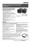
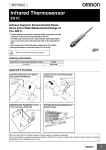
Infrared Thermosensor
ES1B
Achieve Low-cost Measurements with an
Infrared Thermosensor.
• Non-contact measurement.
• The ES1B has an electromotive output as high as that of a thermocouple, thus connecting directly to the thermocouple input terminal
of the Temperature Controller is possible.
• Four temperature ranges are available to cover a wide range of
temperature measurement needs, including those in the food processing, packaging, molding, and electronics industries.
• High-accuracy temperature measurement is ensured by a highspeed response of 300 ms (for a 63% response) and an indication
reproducibility of ±1% PV.
• Unlike thermocouples, the Thermosensor does not deteriorate.
Therefore, stable, real-time temperature control can be maintained.
Ordering Information
■ List of Models
Stock Note: Shaded models are normally stocked.
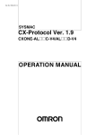
Appearance and sensing characteristic
2 mm
2 dia.
20 mm
20 dia.
40 mm
40 dia.
Specification (temperature range)
60 mm
Model
10 to 70°C
ES1B 10-70C
60 to 120°C
ES1B 60-120C
115 to 165°C
ES1B 115-165C
140 to 260°C
ES1B 140-260C
60 dia.
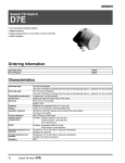
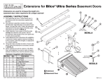
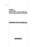
Application Examples
Temperature Control of Ironing Portion
Film
Temperature Measurement of Sheet Molding
Machines and Resin Extrusion Machines
DC
power
supply
Vertical
heating rolls
Resin
ES1B
Conveyor
ES1B
Horizontal
heating rolls
Molding trays
Detecting Excessive Heat Radiation of
High-tension Distribution Boards or Transformers
Detecting Excessive Heat Radiation
of Bearings
ES1B
ES1B
High-tension line
High-tension
distribution
panel
DC
power
supply
Bearing
Note: 1. Either a 12 VDC or 24 VDC power supply is required for the ES1B.
2. The ES1B cannot be used with OMRON’s E5ZE
Multipoint Temperature Controller. (It can be used
with the E5ZN, E5AR, and E5ER.)
Infrared Thermosensor
ES1B
1
Specifications
■ Ratings/Characteristics
Item
ES1B
Power supply voltage
12/24 VDC
Operating voltage range
90% to 110% of the power supply voltage
Current consumption
20 mA max.
Measuring temperature range
Accuracy
(See note 1.)
10 to 70°C, 60 to 120°C, 115 to 165°C, 140 to 260°C
±5°C (See note 2.)
±2% PV or ±2°C, whichever is larger
±10°C (See note 2.)
±4% PV or ±4°C, whichever is larger
±30°C (See note 2.)
±6% PV or ±6°C, whichever is larger
±40°C (See note 2.)
±8% PV or ±8°C, whichever is larger
Reproducibility
±1% PV or ±1°C, whichever is larger
Temperature drift
0.4°C/°C max.
Sensing distance vs. sensing diameter
1:1 typ.
Measurement wavelength
6.5 to 14.0 µm
Receiver element
Thermopile
Response speed
Approximately 300 ms at response rate of 63%
Output impedance
1 to 4 kΩ
Operating temperature
−25°C to 70°C (with no icing or condensation)
Allowable ambient humidity
35% to 85%
Vibration resistance (destruction)
98 m/s2 for 2 hours each in X, Y, and Z directions at 10 to 55 Hz
Shock resistance (destruction)
300 m/s2 for 3 times each in X, Y, and Z directions
Casing material
ABS resin
Degree of protection
IP65
Weight
Approx. 120 g
Cable
Compensating conductor: 3 m
PVC-covered cable with a shield wire resisting 70°C
Note: 1. Based on characteristics of K-type thermocouple and radiation rate of 0.9.
2. The accuracy is given as the change in temperature from any reference temperature of the sensing object. For example, if the reference
temperature is 50°C, the accuracy at 55°C would be ±2% PV or ±2°C, whichever is larger and the accuracy at 60°C would be ±4% PV or
±4°C, whichever is larger.
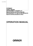
Connections
Green, Output +
+
White, Output −
Thermocouple
(K)
- input terminals
Temperature Controller
Orange, Power +
12/24 VDC
Shield, Power −
GND
DC power supply
2
Infrared Thermosensor ES1B
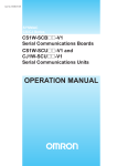
Dimensions
Note: All units are in millimeters unless otherwise indicated (inch).
ES1B
(1.75)
44.5
6.5
(.70) 17.8
3m
3,000
ABS resin
Polyolefin tube
Mounting Lock Nuts (Two) (Provided)
Green, Output +
White, Output −
14.2 dia.
15
36.5
PVC-covered
(−25°C to 70°C)
Screw M18×1.0
Orange, Power +
Shield, Power −
(.94) 24
26
7
(1.02)
(.59)
Adjustment Methods
Adjust the Thermosensor as described below before using it.
Adjust the Thermosensor according to the conditions of the sensing object and characteristics of the
Temperature Controller.
Offset Compensation for Target Value with Input Shift Function
The error caused at the
time the Thermosensor is
connected to the
Temperature Controller.
PV display of
Temperature
Controller
Temperature
characteristics of
target sensing object
Compensated with the
input shift function of
the Temperature
Controller
Temperature Controller
(such as E5CS)
Target value
(Actual temperature of sensing object sample)
Gain and Offset Compensation with Two-point Shift Function
PV display of
Temperature
Controller
Upper limit of
SV of
Temperature
Controller
Temperature Controller
(such as E5@N or E5@K)
Lower limit side
The error caused by
the condition of the
sensing objects or at
the time the Thermosensor is
connected to the
Temperature Controller.
Upper limit side
Compensated with the
two-point shift function
(for the upper and
lower sides) of the
Temperature
Controller.
Lower limit of SV of
Temperature Controller
Target value
(Actual temperature of sensing object sample)
Infrared Thermosensor
ES1B
3
■ One-point Input Shift
■ Two-point Input Shift
Use a two-point input shift to output more accurate display values.
Preparations
• Set a temperature input range that is suitable for the input specifications of the Infrared Thermosensor.
• Prepare a thermometer to measure the temperature of the sensing
object as shown in figure 1, below.
Configuration for Offsetting the Infrared
Thermosensor Input (Figure 1)
(C) Sensing
object
Preparations
Refer to the preparations for a one-point input shift.
1. The input value is shifted at two points: near room temperature
and near the set point. Check the temperature of the sensing
object (C) and the temperature indicated on the Controller (A) at
both near room temperature and near the set point.
2. Use the following formulas to calculate the upper-limit temperature input and lower-limit temperature input settings based on the
values checked above.
Diagram of Two-point Input Shift
Temperature indicated
by Controller (A)
After offset
ES1B Infrared
Thermosensor
Upper limit of
set range, YH
(e.g., 260˚C)
−
+
Output
(+,−)
Indicated temp. after
offset, X2 (e.g., 110˚C)
Power supply
(+,−)
Power
Supply
Indicated temp. after
offset, Y1 (e.g., 40˚C)
Indicated temp. after
offset, X1 (e.g., 25˚C)
Lower-limit
temperature
input insl 0
Lower limit of
set range,
YL (e.g., 0˚C)
Example for the E5CN
C
insl
10
Lower-limit
temperature input
C
insh
10
insl=
Upper-limit
temperature input
Temperature indicated
by Controller (A)
4
Temperature
indicated by
thermometer (B)
YL−Y1
×{(X2−Y2)−(X1−Y1)}+(X1−Y1)
Y2−Y1
Upper-limit Temperature Input Setting
Diagram of One-point Input Shift
0
X1, Room temp. X2, Near set point
(e.g., 25˚C)
(e.g., 110˚C)
Lower-limit Temperature Input Setting
1. Adjust the temperature of the sensing object (C) in the configuration shown in figure 1 to near the set point. We will assume that
the temperature indicated on the thermometer is the actual temperature of the sensing object.
2. Check the temperature of the sensing object (C) and the temperature indicated on the Controller (A) and set both the upper-limit
and lower-limit temperature input settings to the following value:
Temperature C (sensing object) - Temperature A (Controller)
3. Check the temperature of the sensing object (C) and the temperature indicated on the Controller (A) again. If they are about the
same, then the offset has been properly set.
Indicated temperature
after offset
(e.g., 120˚C)
Indicated temperature
before offset
(e.g., 110˚C)
Before offset
Indicated temp. before
offset,Y2 (e.g., 105˚C)
(B) Thermometer
(A) Temperature
Controller
Upper-limit
temperature input insh
After offset
Input offset value
(e.g., 10˚C)
Before offset
Near set point Temperature
(e.g., 120˚C) indicated by
thermometer (B)
Infrared Thermosensor ES1B
insh=
YH−Y1
×{(X2−Y2)−(X1−Y1)}+(X1−Y1)
Y2−Y1
3. Set both the upper-limit and lower-limit temperature input settings
and then check the temperature of the sensing object (C) and the
temperature indicated on the Controller (A) both near room temperature and near the set point.
4. Although we have used two points, near room temperature and
near the set point, accuracy can be increased further by using
another point within the measurement temperature range other
than the set value of room temperature.
Example for the E5CN
C
insl
C
insh
-27
53
Lower-limit
temperature input
Upper-limit
temperature input
In this example, the ES1B is used between 140 and 260°C. Here, the
set point lower limit, YL, would be 0°C and the set point upper limit,
YH, would be 260°C in formulas 1 and 2. The temperatures of the
sensing object are checked next.
The offset values can be calculated as shown below when the Controller display Y1 is 40°C for a room temperature X1 of 25°C and
when the Controller display Y2 is 105°C for a set point temperature
X2 of 110°C
Upper-limit Temperature Input Setting
insl=
0−40
×{(110−105)−(25−40)}+(25−40)
105−40
= −27.3 (°C)
Lower-limit Temperature Input Setting
insh=
260−40
×{(110−105)−(25−40)}+(25−40)
105−40
= 52.7 (°C)
Infrared Thermosensor
ES1B
5
Precautions
!CAUTION
If this product should malfunction and cease to provide
correct output, property damage may occur to the
equipment or device that is connected to it. To prevent
this, provide additional safety measures by also
connecting the equipment or devices to a separate alarm
system that will warn operators of temperature increase.
Precautions for Safe Use
1. Use the ES1B only within the ranges specified by its specifications and ratings.
2. Be sure to correctly wire the input sensor leads to the proper positive and negative terminals.
3. Do not use the product in the following locations:
• Locations subject to icing or condensation.
• Locations subject to excessive shocks or vibration.
• Locations subject to dust or corrosive gases.
• Locations subject to extreme temperature changes or direct
sunlight.
• Locations subject to water splashing or oil contact.
Precautions for Correct Use
1. The thermocouple output and power supply are not isolated.
Make sure that unwanted circuit paths are not formed with the
equipment or device that is connected to the product.
2. To prevent inductive noise, wire the product separately from highvoltage sources and power lines carrying large currents. Also
avoid parallel wiring or shared wiring paths with power lines.
3. Do not allow the filter to become soiled. Use air blow or use a thin
cotton swab to clean the filter.
1. Installation
• Select a place where the emissivity is high for measuring the target.
If necessary, use black spray or black tape.
• Use the supplied locknuts to fix the ES1B securely in place. Tighten
to a torque of 0.5 N·m max.
• When measuring a high-temperature object, use a shield or similar
protection to prevent the temperature of the ES1B from rising.
2. Connection
• Connect to the green output lead wire (+), white output lead wire
(−), orange power supply lead wire (+), and shield power supply
wire (−).
• To measure the temperature difference between two locations, use
two isolated power supplies.
3. Adjustment
• The output impedance of the ES1B is 1 to 4 kΩ. Normally, current
leaking to the ES1B from the burnout detection circuit of the temperature controller will offset the measured temperature in a range
extending from several degrees to several tens of degrees. When
using a controller equipped with an input shift function, use the
input shift function to compensate for this offset error in the vicinity
of the measuring temperature. For details on this compensation,
see Input Shift Method section and the user's manual of the controller being used.
• If the length of a lead wire must be extended, use a K thermocouple
compensating conductor for the output lead wires (+, −), and standard copper wire for power supply leads (+, −).
• Do not bend lead wires repeatedly.
4. Cleaning
• Do not use paint thinner or the equivalent for cleaning. Use standard grade alcohol.
6
Infrared Thermosensor ES1B
Certain Terms and Conditions of Sale
1. Offer; Acceptance. These terms and conditions (these "Terms") are deemed
part of all catalogs, manuals or other documents, whether electronic or in writing, relating to the sale of goods or services (collectively, the "Goods") by
Omron Electronics LLC and its subsidiary companies ("Seller"). Seller hereby
objects to any terms or conditions proposed in Buyer's purchase order or other
documents which are inconsistent with, or in addition to, these Terms. Please
contact your Omron representative to confirm any additional terms for sales
from your Omron company.
2. Prices. All prices stated are current, subject to change without notice by
Seller. Buyer agrees to pay the price in effect at time of shipment.
3. Discounts. Cash discounts, if any, will apply only on the net amount of
invoices sent to Buyer after deducting transportation charges, taxes and
duties, and will be allowed only if (i) the invoice is paid according to Seller's
payment terms and (ii) Buyer has no past due amounts owing to Seller.
4. Orders. Seller will accept no order less than $200 net billing.
5. Governmental Approvals. Buyer shall be responsible for, and shall bear all
costs involved in, obtaining any government approvals required for the importation or sale of the Goods.
6. Taxes. All taxes, duties and other governmental charges (other than general
real property and income taxes), including any interest or penalties thereon,
imposed directly or indirectly on Seller or required to be collected directly or
indirectly by Seller for the manufacture, production, sale, delivery, importation,
consumption or use of the Goods sold hereunder (including customs duties
and sales, excise, use, turnover and license taxes) shall be charged to and
remitted by Buyer to Seller.
7. Financial. If the financial position of Buyer at any time becomes unsatisfactory
to Seller, Seller reserves the right to stop shipments or require satisfactory
security or payment in advance. If Buyer fails to make payment or otherwise
comply with these Terms or any related agreement, Seller may (without liability
and in addition to other remedies) cancel any unshipped portion of Goods sold
hereunder and stop any Goods in transit until Buyer pays all amounts, including amounts payable hereunder, whether or not then due, which are owing to it
by Buyer. Buyer shall in any event remain liable for all unpaid accounts.
8. Cancellation; Etc. Orders are not subject to rescheduling or cancellation
unless Buyer indemnifies Seller fully against all costs or expenses arising in
connection therewith.
9. Force Majeure. Seller shall not be liable for any delay or failure in delivery
resulting from causes beyond its control, including earthquakes, fires, floods,
strikes or other labor disputes, shortage of labor or materials, accidents to
machinery, acts of sabotage, riots, delay in or lack of transportation or the
requirements of any government authority.
10. Shipping; Delivery. Unless otherwise expressly agreed in writing by Seller:
a. Shipments shall be by a carrier selected by Seller;
b. Such carrier shall act as the agent of Buyer and delivery to such carrier
shall constitute delivery to Buyer;
c. All sales and shipments of Goods shall be FOB shipping point (unless otherwise stated in writing by Seller), at which point title to and all risk of loss of
the Goods shall pass from Seller to Buyer, provided that Seller shall retain a
security interest in the Goods until the full purchase price is paid by Buyer;
d. Delivery and shipping dates are estimates only.
e. Seller will package Goods as it deems proper for protection against normal
handling and extra charges apply to special conditions.
11. Claims. Any claim by Buyer against Seller for shortage or damage to the
Goods occurring before delivery to the carrier must be presented in writing to
Seller within 30 days of receipt of shipment and include the original transportation bill signed by the carrier noting that the carrier received the Goods from
Seller in the condition claimed.
12. Warranties. (a) Exclusive Warranty. Seller's exclusive warranty is that the
Goods will be free from defects in materials and workmanship for a period of
twelve months from the date of sale by Seller (or such other period expressed
in writing by Seller). Seller disclaims all other warranties, express or implied.
(b) Limitations. SELLER MAKES NO WARRANTY OR REPRESENTATION,
EXPRESS OR IMPLIED, ABOUT NON-INFRINGEMENT, MERCHANTABILITY OR FITNESS FOR A PARTICULAR PURPOSE OF THE GOODS.
BUYER ACKNOWLEDGES THAT IT ALONE HAS DETERMINED THAT THE
GOODS WILL SUITABLY MEET THE REQUIREMENTS OF THEIR
INTENDED USE. Seller further disclaims all warranties and responsibility of
any type for claims or expenses based on infringement by the Goods or otherwise of any intellectual property right. (c) Buyer Remedy. Seller's sole obligation hereunder shall be to replace (in the form originally shipped with Buyer
responsible for labor charges for removal or replacement thereof) the noncomplying Good or, at Seller's election, to repay or credit Buyer an amount
equal to the purchase price of the Good; provided that in no event shall Seller
be responsible for warranty, repair, indemnity or any other claims or expenses
regarding the Goods unless Seller's analysis confirms that the Goods were
properly handled, stored, installed and maintained and not subject to contamination, abuse, misuse or inappropriate modification. Return of any goods by
Buyer must be approved in writing by Seller before shipment. Seller shall not
be liable for the suitability or unsuitability or the results from the use of Goods
in combination with any electrical or electronic components, circuits, system
assemblies or any other materials or substances or environments. Any
advice, recommendations or information given orally or in writing, are not to be
construed as an amendment or addition to the above warranty.
13. Damage Limits; Etc. SELLER SHALL NOT BE LIABLE FOR SPECIAL, INDIRECT OR CONSEQUENTIAL DAMAGES, LOSS OF PROFITS OR PRODUCTION OR COMMERCIAL LOSS IN ANY WAY CONNECTED WITH THE
GOODS, WHETHER SUCH CLAIM IS BASED IN CONTRACT, WARRANTY,
NEGLIGENCE OR STRICT LIABILITY. Further, in no event shall liability of
Seller exceed the individual price of the Good on which liability is asserted.
14. Indemnities. Buyer shall indemnify and hold harmless Seller, its affiliates and
its employees from and against all liabilities, losses, claims, costs and
expenses (including attorney's fees and expenses) related to any claim, investigation, litigation or proceeding (whether or not Seller is a party) which arises
or is alleged to arise from Buyer's acts or omissions under these Terms or in
any way with respect to the Goods. Without limiting the foregoing, Buyer (at
its own expense) shall indemnify and hold harmless Seller and defend or settle
any action brought against Seller to the extent that it is based on a claim that
any Good made to Buyer specifications infringed intellectual property rights of
another party.
15. Property; Confidentiality. The intellectual property embodied in the Goods is
the exclusive property of Seller and its affiliates and Buyer shall not attempt to
duplicate it in any way without the written permission of Seller. Notwithstanding any charges to Buyer for engineering or tooling, all engineering and tooling
shall remain the exclusive property of Seller. All information and materials
supplied by Seller to Buyer relating to the Goods are confidential and proprietary, and Buyer shall limit distribution thereof to its trusted employees and
strictly prevent disclosure to any third party.
16. Miscellaneous. (a) Waiver. No failure or delay by Seller in exercising any right
and no course of dealing between Buyer and Seller shall operate as a waiver
of rights by Seller. (b) Assignment. Buyer may not assign its rights hereunder
without Seller's written consent. (c) Amendment. These Terms constitute the
entire agreement between Buyer and Seller relating to the Goods, and no provision may be changed or waived unless in writing signed by the parties.
(d) Severability. If any provision hereof is rendered ineffective or invalid, such
provision shall not invalidate any other provision. (e) Setoff. Buyer shall have
no right to set off any amounts against the amount owing in respect of this
invoice. (f) As used herein, "including" means "including without limitation".
Certain Precautions on Specification and Use
1. Suitability of Use. Seller shall not be responsible for conformity with any standards, codes or regulations which apply to the combination of the Good in the
Buyer's application or use of the Good. At Buyer's request, Seller will provide
applicable third party certification documents identifying ratings and limitations
of use which apply to the Good. This information by itself is not sufficient for a
complete determination of the suitability of the Good in combination with the
end product, machine, system, or other application or use. The following are
some examples of applications for which particular attention must be given.
This is not intended to be an exhaustive list of all possible uses of this Good,
nor is it intended to imply that the uses listed may be suitable for this Good:
(i) Outdoor use, uses involving potential chemical contamination or electrical
interference, or conditions or uses not described in this document.
(ii) Energy control systems, combustion systems, railroad systems, aviation
systems, medical equipment, amusement machines, vehicles, safety
equipment, and installations subject to separate industry or government
regulations.
(iii) Systems, machines and equipment that could present a risk to life or
property. Please know and observe all prohibitions of use applicable to
this Good.
NEVER USE THE PRODUCT FOR AN APPLICATION INVOLVING SERIOUS
RISK TO LIFE OR PROPERTY WITHOUT ENSURING THAT THE SYSTEM
AS A WHOLE HAS BEEN DESIGNED TO ADDRESS THE RISKS, AND THAT
THE SELLER'S PRODUCT IS PROPERLY RATED AND INSTALLED FOR
THE INTENDED USE WITHIN THE OVERALL EQUIPMENT OR SYSTEM.
2. Programmable Products. Seller shall not be responsible for the user's pro
gramming of a programmable Good, or any consequence thereof.
3. Performance Data. Performance data given in this catalog is provided as a
guide for the user in determining suitability and does not constitute a warranty
It may represent the result of Seller's test conditions, and the user must corre
late it to actual application requirements. Actual performance is subject to the
Seller's Warranty and Limitations of Liability.
4. Change in Specifications. Product specifications and accessories may be
changed at any time based on improvements and other reasons. It is our prac
tice to change part numbers when published ratings or features are changed
or when significant construction changes are made. However, some specifica
tions of the Good may be changed without any notice. When in doubt, specia
part numbers may be assigned to fix or establish key specifications for you
application. Please consult with your Seller's representative at any time to con
firm actual specifications of purchased Good.
5. Errors and Omissions. The information in this catalog has been carefully
checked and is believed to be accurate; however, no responsibility is assumed
for clerical, typographical or proofreading errors, or omissions.
Infrared Thermosensor
ES1B
7
Complete “Terms and Conditions of Sale” for product purchase and use are on Omron’s website
at www.omron.com/oei – under the “About Us” tab, in the Legal Matters section.
ALL DIMENSIONS SHOWN ARE IN MILLIMETERS.
To convert millimeters into inches, multiply by 0.03937. To convert grams into ounces, multiply by 0.03527.
OMRON ELECTRONICS LLC
OMRON CANADA, INC.
OMRON ON-LINE
One Commerce Drive
Schaumburg, IL 60173
885 Milner Avenue
Toronto, Ontario M1B 5V8
847-843-7900
416-286-6465
Global - http://www.omron.com
USA - http://www.omron.com/oei
Canada - http://www.omron.ca
For US technical support or other inquiries:
800-556-6766
Cat. No. H127-E3-01
8
8/04
Specifications subject to change without notice
Infrared Thermosensor ES1B
Printed in USA