1
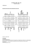
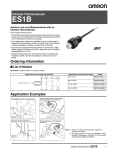
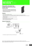
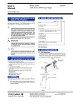
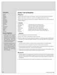
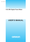
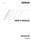
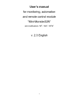
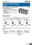
Infrared Thermosensor
ES1C
Achieve Superior Environmental Resistance and a Wide Measurement Range of
0 to 400°C.
• Flexible placement with slim cylindrical shape and long focus with
a distance of 500 mm and area diameter of 80 mm.
• The SUS body and silicon lens resist ambient operating temperatures of up to 70°C and resist dust and water to the equivalent of
IP67.
• Fast measurement with high-speed response of 100 ms/90%.
• Strong resistance to noise with output of 4 to 20 mA.
Refer to the Safety Precautions on page 6.
Ordering Information
Specification (measuring temperature range)
Model
0 to 400°C
ES1C-A40
Application Examples
Checking Temperatures for Fabrication and Molding Materials
Quality Control in the Thermal Sheet
Processing
Digital Temperature Controller
E5CN-@L
Digital Panel Meter
K3GN-ND@
Monitoring the Temperature of Liquid Crystal Glass Substrates
Checking the Drying Temperature in
Baked Coatings
Modular Temperature Controller
EJ1
Digital Panel Meter
K3HB-X
Do not use the ES1C in locations subject to rapid changes in ambient temperature.
Use a heat shield to suppress temperature changes if the ES1C is used in a location that is subject to rapid changes in ambient
temperature due to radiating heat or hot air.
1
ES1C
Ratings and Characteristics
Item
Model
ES1C
Power supply voltage
12 to 24 VDC
Operating voltage range
90% to 110% of rated voltage
Current consumption
70 mA max.
Measuring temperature range
0 to 400°C
Measurement accuracy
0 to 200°C: ±2°C, 201 to 400°C: ±1% (emissivity: 0.95)
Response time
100 ms/90%
Reproducibility
±1°C of reading value
Measurement wavelength
8 to 14 µm
Light-receiving element
Thermopile
Emissivity
0.95 fixed
Current output
4 to 20 mA DC, Load: 250 Ω max.
Ambient temperature range
Operating: 0 to 70°C, Storage: −20 to 70°C (with no icing or condensation)
Ambient humidity range
Operating and storage: 35% to 85%
Vibration resistance (destruction) 1.5-mm amplitude at 10 to 55 Hz for 2 hours each in the X, Y, and Z directions
Weight
180 g
Degree of protection
Equivalent to IP67
Connections
Measurement Range
Power supply:
12 to 24 VDC
Brown
110 dia.
80 dia.
70 dia.
+
300
Blue
500
−
Black
4 to 20 mA DC
+
1000
+
8888
Gray
−
−
[mm]
Connected
device
Note: The measurement range is the measurement diameter for an optical
response of 90%. Make sure that the actual object to be measured is
sufficiently larger than the measurement diameters in the above figure.
F.G.
Shield
Dimensions
(Unit: mm)
ES1C
12 dia. (lens diameter)
M18×P1.0
60 (threaded section)
24
2
120
2,000
(cable length)
ES1C
Characteristics of Infrared Thermosensors
1. Principles of Infrared Thermosensors
2. Measurement Error due to Emissivity
The ES1C uses thermopile light-receiving elements to receive
the specific wavelengths (8 to 14 µm) in the infrared range radiated from the measurement range of the measurement object, converts the received light into an output signal in the
internal circuits, and outputs a current that corresponds to the
measured temperature.
The ES1C outputs a current of 4 to 20 mA for measurement
object temperatures of 0 to 400°C at a emissivity of 0.95. If the
emissivity of the measurement object is less than 0.9, the effects of the ambient temperature will cause measurement error. Glossy metal surfaces generally have an extremely low
emissivity, and so operation is easily affected by the ambient
temperature, and it is difficult to measure the temperature of
the measurement object. (Refer to the emissivities that are
given on page 5.)
In an application like this, select a location with a high emissivity and use the ES1-T Black Tape (sold separately, emissivity
of 0.95) or ES1-S Black Spray (sold separately, emissivity of
0.94).
Internal circuit
Output signal
(4 to 20 mA)
Measurement
object
Measurement range
Thermopile
Setting and Adjusting the Connected Device
This section describes an example of making settings and adjustments when a Digital Temperature Controller and Digital Panel
Meter are connected.
1. Mounting
• Select a location with a high emissivity for the object to be
measured. If required, use Black Spray or Black Tape.
• Secure the Thermosensor with the enclosed lock nuts. Use
a tightening torque of 20 N·m max.
• Mount the Thermosensor so that it is perpendicular to the
object to be measured.
• Mount the Thermosensor in a location that is not subject to
ambient temperatures above 70°C, to direct hot air, etc.
2. Setting the Connected Device
Make the settings so that 0.0 to 400.0°C is displayed for an
output of 4 to 20 mA for the ES1C.
E5@N-@L Digital Temperature
Controller (Analog Input)
Input type
K3GN-ND@ Digital Panel
Meter (DC Input)
0 (4 to 20 mA) Input type
Scaling upper limit
4,000
Analog range
Analog
4 to 20
Scaling lower limit
0
Scaling display
value 1
Decimal point position
1
Scaling display
value 2
4,000
Decimal point position
0000.0
0
● Adjustment Example for the E5@N-L (Analog Input)
A Shift Method
1. Measuring the Temperature of the Measurement Object
Use the thermometer (B) to measure the actual temperature when using the measurement object (C).
2. Shifting the Display Value of the Connected Device
Adjust the settings of the connected device after checking
the following value:
Temperature B (thermometer) − Temperature A (connected device)
If temperature B minus temperature A is 10.0, adjust the
settings so that measurement value of the connected device is +10.0.
• Scaling upper limit = 4,000 to 4,100
• Scaling lower limit = 0 to 100
(The setting for the decimal point position is 1, and so the
scaling set value will be increased by 100 for a displayed
value of +10.0.)
Value indicated by connected device (A)
(°C)
* For details, refer to the User’s Manual for the connected device.
3. Adjusting the Connected Device
Error may occur due to the emissivity of the measurement environment or measurement object. There are two easy methods that can be used to adjust the error: simple shifting and
two-point shifting, as described in the following section.
Setup for Adjustment
Value indicated after
shift (e.g., 100.0)
Value indicated before
shift (e.g., 90.0)
After shift
Before shift
+10.0
Measurement object
temperature (e.g., 100°C)
Temperature indicated
(°C) by thermometer (B)
Measurement object (C)
ES1C
Thermometer (B)
Connected device (A)
Power supply (D)
3
ES1C
B Two-point Shift
1. Measuring the Temperature of the Measurement Object
Set the temperature of the measurement object to room
temperature and to the temperature during operation, and
check the values indicated by the connected device (A)
and the temperatures of the measurement object (B).
Value indicated by Temperature of meaconnected device (A) surement object (B)
Room temperature
Y1
X1
Temperature
during operation
Y2
X2
2. Shifting the Indicated Value
Use the following formula to calculate the upper limit and
lower limit of input scaling after the shift from the values Y1
and Y2 indicated by the connected device and temperatures X1 and X2 of the measurement object.
Value indicated by connected device (A)
● Adjustment Example for the K3GN
A Shift Method
1. Measuring the Temperature of the Measurement Object
Use a thermometer (B) to measure the actual temperature
when using the measurement object (C).
2. Shifting the Display Value
Adjust the settings of the connected device after checking
the following value:
Temperature B (thermometer) − Temperature A (connected device)
If temperature B minus temperature A is 10.0, adjust the
settings so that measurement value of the connected device is +10.0.
• Scaling display value 1 = 0 to 100
• Scaling display value 2 = 4,000 to 4,100
(The setting for the decimal point position is 0000.0, and so
the scaling set value will be increased by 100 for a displayed value of +10.0.)
Value indicated by connected device (A)
(°C)
(°C)
After shift
After shift
Value indicated after shift
(e.g., 100.0)
Before shift
Value Y2 indicated before
shift (e.g., 90.0)
+10.0
Value indicated before
shift (e.g., 90.0)
Value Y1 indicated before
shift (e.g., 30.0)
Value indicated after shift
(e.g., 25.0)
Before shift
Value indicated after shift
(e.g., 100.0)
Temperature
displayed by
X1 room
X2 temperature
temperature during operation (°C) thermometer (B)
(e.g., 25°C)
Temperature
displayed by
(°C) thermometer (B)
Measurement
object temperature
(e.g., 100°C)
(e.g., 100°C)
(1) Scaling upper limit after shift (°C)
X2 – X1
= --------------------- ( 400 – Y1 ) + X1
Y2 – Y1
(2) Scaling lower limit after shift (°C)
X2 – X1
= --------------------- ( 0 – Y1 ) + X1
Y2 – Y1
Change the values to the scaling upper and lower limits
from the result considering the decimal point position. For
example, if the scaling upper limit after shift is 487.5 (°C)
and the scaling lower limit after shift is −12.5 (°C), the decimal point position of the connected device will be set to the
first decimal position, and so the scaling upper limit will be
set to 4,875 and the scaling lower limit to −125.
B Two-point Shift
Use the teaching function of the K3GN to make adjustments
using the ES1C's actual analog input value and the actual temperature. Set one of the two teaching points to room temperature and the other to the actual temperature of the
measurement object during operation.
1. Move the K3GN to the initial setting level.
2. Set the temperature of the object to be measured to room
temperature and set scaling input value 1 using teaching.
Next, set the temperature (B) of the thermometer to scaling display value 1. (Point A in the following figure. The
decimal point position for the K3GN is set to the first decimal position, and so set 250 for 25.0°C.)
3. Next, set the measurement object to the actual operating
temperature and set scaling input value 2 and scaling display value 2 in step 2. (A value of 1,000 is set to specify
100.0°C for point B in the following graph.)
Value indicated by connected device (A)
(°C)
Measurement object at room
temperature (e.g., 25°C)
B
Scaling display value 2
(e.g., 100.0°C)
Scaling display value 1
(e.g., 25.0°C)
A
Input value of
connected
(mA) device
0
Scaling input value 1
(e.g., 5.01 mA)
4
Measurement object at operating
temperature (e.g., 100°C)
Scaling input value 2
(e.g., 8.02 mA)
ES1C
Emissivities
Item
Emissivity
Item
Aluminum
Iron oxide
Pure aluminum, high-gloss aluminum
0.04 to 0.06
Red rusted iron
0.76
Gray oxidized lead
Commercially available aluminum
sheets
0.09
Mercury
0.09 to 0.12
Molybdenum filament
0.10 to 0.20
High-gloss sheets of pure brass
Brass oxide
0.10
0.08 to 0.36
Chrome oxide
0.81
Glossy
0.07
Nickel oxide
0.90
Platinum
Copper
Glossy platinum sheets
0.05 to 0.10
Platinum wire rods
0.07 to 0.18
Glossy
0.05
Copper oxide
0.78
Glossy pure silver
0.55
Stainless steel
0.02 to 0.03
Glossy
0.07
Rolled stainless steel
0.45
Bronze with uneven surface
Glossy pure gold
Iron and steel (except stainless)
Glossy iron
0.14 to 0.38
0.03 to 0.28
Glossy tin
0.06
Glossy cast iron
0.21
Etched tungsten filament
Glossy wrought iron
0.28
Zinc
Oxidized dull-colored wrought iron
0.94
Commercially available glossy pure zinc
0.03 to 0.35
0.05
Rusty iron sheet
0.69
Galvanized sheets
Glossy steel
0.07
Zinc oxide
0.11 to 0.28
Thin rolled steel sheets
0.66
Titanium oxide
0.40 to 0.60
Unpolished steel sheets
0.94 to 0.97
Item
Asbestos
Emissivity
Item
0.21
Emissivity
0.93 to 0.94
Water
0.92 to 0.96
Ice
0.96 to 0.98
Red, unpolished
0.93
Snow
0.83
Fireclay
0.75
Glass
0.85 to 0.95
Ceramics
0.90 to 0.94
Bricks
Carbon
Filament
0.53
Marble
0.94
Soot film
0.84 to 0.95
Fluorite
0.30 to 0.40
Gypsum
0.80 to 0.90
Plaster
0.89 to 0.91
Brick (red)
0.93 to 0.95
Paint, lacquer, varnish
Coated lacquer
0.80 to 0.95
White enamel
0.91
Black lacquer
0.96 to 0.98
Fibers
Aluminum paint
0.27 to 0.67
Cloth (black)
0.98
16-color oil-based paint
0.92 to 0.96
Skin (human)
0.98
Glazed porcelain
0.92
Leather
Opaque crystals (quartz)
0.68 to 0.92
Charcoal (powder)
Asphalt
0.90 to 0.98
Rubber (black)
Concrete
0.94
Plastic
Cement
0.96
Lumber
Sand
0.90
Paper
Dirt
0.28
Nickel
0.56 to 0.64
Glossy chrome
Nonmetals
0.69
Aluminum oxide
Brass
Metals
Emissivity
0.78 to 0.82
0.90
0.75 to 0.80
0.96
0.94
0.85 to 0.95
0.90
0.70 to 0.94
0.92 to 0.96
Note: Operation will be easily affected by the ambient temperature if the emissivity of the measurement object is lower than 0.9. Glossy metal surfaces generally have
an extremely low emissivity, and it is difficult to measure the temperature of the measurement object. Use Black Spray or Black Tape (sold separately).
5
ES1C
Safety Precautions
CAUTION
A malfunction in the product may occasionally
result in property damage to connected equipment or devices. To maintain safety in the
event of malfunction of the product, take
appropriate safety measures, such as installing a monitoring device on a separate line.
Precautions for Safe Use
(1) This Product is designed for indoor use only. Do not use
the Product outdoors or in any of the following locations.
• Locations directly subject to heat radiated from heating
equipment.
• Locations subject to splashing liquid or oil atmosphere.
• Locations subject to direct sunlight.
• Locations subject to dust or corrosive gases (in particular, sulfide or ammonia gases).
• Locations subject to intense temperature changes.
• Locations subject to icing or condensation.
• Locations subject to excessive vibration or shock.
(2) Use and store the Product within the rated ambient temperature and humidity. If there is heating equipment in the
vicinity of the Product, heat radiated from the equipment
will cause the temperature inside the Product to rise and
shorten its service life. In such a case, use forced cooling
by fans or other means of air ventilation.
(3) Be sure to wire properly with correct polarity of terminals.
(4) Attach a surge protector or noise filter on nearby noisegenerating devices (in particular, motors, transformers,
solenoids, magnetic coils, or devices that have an inductance component). If a noise filter is used on the power
supply, check the voltage and current, and attach the
noise filter as near as possible to the Product. Allow as
much space as possible between the product and devices
that generates high frequencies (such as high-frequency
welders and high-frequency sewing machines) or surges.
(5) Use the product within the rated load and power supply.
(6) The current output and power supply are not isolated. Be
sure that unwanted currents do no occur with the connected device.
(7) Do not measure glossy surfaces.
(8) Do not let the Product touch the object to be measured.
(9) Do not touch the lens.
(10) Do not allow charged objects in the vicinity of the Product.
6
Terms and Conditions of Sale
1. Offer; Acceptance. These terms and conditions (these "Terms") are deemed
part of all quotes, agreements, purchase orders, acknowledgments, price lists,
catalogs, manuals, brochures and other documents, whether electronic or in
writing, relating to the sale of products or services (collectively, the "Products")
by Omron Electronics LLC and its subsidiary companies (“Omron”). Omron
objects to any terms or conditions proposed in Buyer’s purchase order or other
documents which are inconsistent with, or in addition to, these Terms.
2. Prices; Payment Terms. All prices stated are current, subject to change without notice by Omron. Omron reserves the right to increase or decrease prices
on any unshipped portions of outstanding orders. Payments for Products are
due net 30 days unless otherwise stated in the invoice.
3. Discounts. Cash discounts, if any, will apply only on the net amount of invoices
sent to Buyer after deducting transportation charges, taxes and duties, and will
be allowed only if (i) the invoice is paid according to Omron’s payment terms
and (ii) Buyer has no past due amounts.
4. Interest. Omron, at its option, may charge Buyer 1-1/2% interest per month or
the maximum legal rate, whichever is less, on any balance not paid within the
stated terms.
5. Orders. Omron will accept no order less than $200 net billing.
6. Governmental Approvals. Buyer shall be responsible for, and shall bear all
costs involved in, obtaining any government approvals required for the importation or sale of the Products.
7. Taxes. All taxes, duties and other governmental charges (other than general
real property and income taxes), including any interest or penalties thereon,
imposed directly or indirectly on Omron or required to be collected directly or
indirectly by Omron for the manufacture, production, sale, delivery, importation, consumption or use of the Products sold hereunder (including customs
duties and sales, excise, use, turnover and license taxes) shall be charged to
and remitted by Buyer to Omron.
8. Financial. If the financial position of Buyer at any time becomes unsatisfactory
to Omron, Omron reserves the right to stop shipments or require satisfactory
security or payment in advance. If Buyer fails to make payment or otherwise
comply with these Terms or any related agreement, Omron may (without liability and in addition to other remedies) cancel any unshipped portion of Products sold hereunder and stop any Products in transit until Buyer pays all
amounts, including amounts payable hereunder, whether or not then due,
which are owing to it by Buyer. Buyer shall in any event remain liable for all
unpaid accounts.
9. Cancellation; Etc. Orders are not subject to rescheduling or cancellation
unless Buyer indemnifies Omron against all related costs or expenses.
10. Force Majeure. Omron shall not be liable for any delay or failure in delivery
resulting from causes beyond its control, including earthquakes, fires, floods,
strikes or other labor disputes, shortage of labor or materials, accidents to
machinery, acts of sabotage, riots, delay in or lack of transportation or the
requirements of any government authority.
11. Shipping; Delivery. Unless otherwise expressly agreed in writing by Omron:
a. Shipments shall be by a carrier selected by Omron; Omron will not drop ship
except in “break down” situations.
b. Such carrier shall act as the agent of Buyer and delivery to such carrier shall
constitute delivery to Buyer;
c. All sales and shipments of Products shall be FOB shipping point (unless otherwise stated in writing by Omron), at which point title and risk of loss shall
pass from Omron to Buyer; provided that Omron shall retain a security interest in the Products until the full purchase price is paid;
d. Delivery and shipping dates are estimates only; and
e. Omron will package Products as it deems proper for protection against normal handling and extra charges apply to special conditions.
12. Claims. Any claim by Buyer against Omron for shortage or damage to the
Products occurring before delivery to the carrier must be presented in writing
to Omron within 30 days of receipt of shipment and include the original transportation bill signed by the carrier noting that the carrier received the Products
from Omron in the condition claimed.
13. Warranties. (a) Exclusive Warranty. Omron’s exclusive warranty is that the
Products will be free from defects in materials and workmanship for a period of
twelve months from the date of sale by Omron (or such other period expressed
in writing by Omron). Omron disclaims all other warranties, express or implied.
(b) Limitations. OMRON MAKES NO WARRANTY OR REPRESENTATION,
EXPRESS OR IMPLIED, ABOUT NON-INFRINGEMENT, MERCHANTABIL-
14.
15.
16.
17.
18.
ITY OR FITNESS FOR A PARTICULAR PURPOSE OF THE PRODUCTS.
BUYER ACKNOWLEDGES THAT IT ALONE HAS DETERMINED THAT THE
PRODUCTS WILL SUITABLY MEET THE REQUIREMENTS OF THEIR
INTENDED USE. Omron further disclaims all warranties and responsibility of
any type for claims or expenses based on infringement by the Products or otherwise of any intellectual property right. (c) Buyer Remedy. Omron’s sole obligation hereunder shall be, at Omron’s election, to (i) replace (in the form
originally shipped with Buyer responsible for labor charges for removal or
replacement thereof) the non-complying Product, (ii) repair the non-complying
Product, or (iii) repay or credit Buyer an amount equal to the purchase price of
the non-complying Product; provided that in no event shall Omron be responsible for warranty, repair, indemnity or any other claims or expenses regarding
the Products unless Omron’s analysis confirms that the Products were properly handled, stored, installed and maintained and not subject to contamination, abuse, misuse or inappropriate modification. Return of any Products by
Buyer must be approved in writing by Omron before shipment. Omron Companies shall not be liable for the suitability or unsuitability or the results from the
use of Products in combination with any electrical or electronic components,
circuits, system assemblies or any other materials or substances or environments. Any advice, recommendations or information given orally or in writing,
are not to be construed as an amendment or addition to the above warranty.
See http://www.omron247.com or contact your Omron representative for published information.
Limitation on Liability; Etc. OMRON COMPANIES SHALL NOT BE LIABLE
FOR SPECIAL, INDIRECT, INCIDENTAL, OR CONSEQUENTIAL DAMAGES,
LOSS OF PROFITS OR PRODUCTION OR COMMERCIAL LOSS IN ANY
WAY CONNECTED WITH THE PRODUCTS, WHETHER SUCH CLAIM IS
BASED IN CONTRACT, WARRANTY, NEGLIGENCE OR STRICT LIABILITY.
Further, in no event shall liability of Omron Companies exceed the individual
price of the Product on which liability is asserted.
Indemnities. Buyer shall indemnify and hold harmless Omron Companies and
their employees from and against all liabilities, losses, claims, costs and
expenses (including attorney's fees and expenses) related to any claim, investigation, litigation or proceeding (whether or not Omron is a party) which arises
or is alleged to arise from Buyer's acts or omissions under these Terms or in
any way with respect to the Products. Without limiting the foregoing, Buyer (at
its own expense) shall indemnify and hold harmless Omron and defend or settle any action brought against such Companies to the extent based on a claim
that any Product made to Buyer specifications infringed intellectual property
rights of another party.
Property; Confidentiality. Any intellectual property in the Products is the exclusive property of Omron Companies and Buyer shall not attempt to duplicate it
in any way without the written permission of Omron. Notwithstanding any
charges to Buyer for engineering or tooling, all engineering and tooling shall
remain the exclusive property of Omron. All information and materials supplied
by Omron to Buyer relating to the Products are confidential and proprietary,
and Buyer shall limit distribution thereof to its trusted employees and strictly
prevent disclosure to any third party.
Export Controls. Buyer shall comply with all applicable laws, regulations and
licenses regarding (i) export of products or information; (iii) sale of products to
“forbidden” or other proscribed persons; and (ii) disclosure to non-citizens of
regulated technology or information.
Miscellaneous. (a) Waiver. No failure or delay by Omron in exercising any right
and no course of dealing between Buyer and Omron shall operate as a waiver
of rights by Omron. (b) Assignment. Buyer may not assign its rights hereunder
without Omron's written consent. (c) Law. These Terms are governed by the
law of the jurisdiction of the home office of the Omron company from which
Buyer is purchasing the Products (without regard to conflict of law principles). (d) Amendment. These Terms constitute the entire agreement between
Buyer and Omron relating to the Products, and no provision may be changed
or waived unless in writing signed by the parties. (e) Severability. If any provision hereof is rendered ineffective or invalid, such provision shall not invalidate
any other provision. (f) Setoff. Buyer shall have no right to set off any amounts
against the amount owing in respect of this invoice. (g) Definitions. As used
herein, “including” means “including without limitation”; and “Omron Companies” (or similar words) mean Omron Corporation and any direct or indirect
subsidiary or affiliate thereof.
Certain Precautions on Specifications and Use
1. Suitability of Use. Omron Companies shall not be responsible for conformity
with any standards, codes or regulations which apply to the combination of the
Product in the Buyer’s application or use of the Product. At Buyer’s request,
Omron will provide applicable third party certification documents identifying
ratings and limitations of use which apply to the Product. This information by
itself is not sufficient for a complete determination of the suitability of the Product in combination with the end product, machine, system, or other application
or use. Buyer shall be solely responsible for determining appropriateness of
the particular Product with respect to Buyer’s application, product or system.
Buyer shall take application responsibility in all cases but the following is a
non-exhaustive list of applications for which particular attention must be given:
(i) Outdoor use, uses involving potential chemical contamination or electrical
interference, or conditions or uses not described in this document.
(ii) Use in consumer products or any use in significant quantities.
(iii) Energy control systems, combustion systems, railroad systems, aviation
systems, medical equipment, amusement machines, vehicles, safety equipment, and installations subject to separate industry or government regulations.
(iv) Systems, machines and equipment that could present a risk to life or property. Please know and observe all prohibitions of use applicable to this Product.
NEVER USE THE PRODUCT FOR AN APPLICATION INVOLVING SERIOUS
RISK TO LIFE OR PROPERTY OR IN LARGE QUANTITIES WITHOUT
ENSURING THAT THE SYSTEM AS A WHOLE HAS BEEN DESIGNED TO
2.
3.
4.
5.
ADDRESS THE RISKS, AND THAT THE OMRON’S PRODUCT IS PROPERLY RATED AND INSTALLED FOR THE INTENDED USE WITHIN THE
OVERALL EQUIPMENT OR SYSTEM.
Programmable Products. Omron Companies shall not be responsible for the
user’s programming of a programmable Product, or any consequence thereof.
Performance Data. Data presented in Omron Company websites, catalogs
and other materials is provided as a guide for the user in determining suitability and does not constitute a warranty. It may represent the result of Omron’s
test conditions, and the user must correlate it to actual application requirements. Actual performance is subject to the Omron’s Warranty and Limitations
of Liability.
Change in Specifications. Product specifications and accessories may be
changed at any time based on improvements and other reasons. It is our practice to change part numbers when published ratings or features are changed,
or when significant construction changes are made. However, some specifications of the Product may be changed without any notice. When in doubt, special part numbers may be assigned to fix or establish key specifications for
your application. Please consult with your Omron’s representative at any time
to confirm actual specifications of purchased Product.
Errors and Omissions. Information presented by Omron Companies has been
checked and is believed to be accurate; however, no responsibility is assumed
for clerical, typographical or proofreading errors or omissions.
OMRON INDUSTRIAL AUTOMATION • THE AMERICAS HEADQUARTERS
Schaumburg, IL USA • 847.843.7900 • 800.556.6766 • www.omron247.com
OMRON CANADA, INC. • HEAD OFFICE
Toronto, ON, Canada • 416.286.6465 • 866.986.6766 • www.omron247.com
OMRON ARGENTINA • SALES OFFICE
Cono Sur • 54.11.4783.5300
OMRON ELECTRONICS DE MEXICO • HEAD OFFICE
México DF • 52.55.59.01.43.00 • 001.800.556.6766 • [email protected]
OMRON CHILE • SALES OFFICE
Santiago • 56.9.9917.3920
OMRON ELECTRONICS DE MEXICO • SALES OFFICE
Apodaca, N.L. • 52.81.11.56.99.20 • 001.800.556.6766 • [email protected]
OTHER OMRON LATIN AMERICA SALES
54.11.4783.5300
OMRON ELETRÔNICA DO BRASIL LTDA • HEAD OFFICE
São Paulo, SP, Brasil • 55.11.2101.6300 • www.omron.com.br
OMRON EUROpE B.V. • Wegalaan 67-69, NL-2132 JD, Hoofddorp, The Netherlands. • Tel: +31 (0) 23 568 13 00
Fax: +31 (0) 23 568 13 88 • www.industrial.omron.eu
Cat. No. +-E1-01
02/
Note: Specifications are subject to change.
© 2013 Omron Electronics LLC
Printed in U.S.A.