1
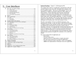
User Manual
Ness Evolution
Multi-media Touch Screen for Ness SmartLiving systems
User Manual
Innovative Electronic Solutions
www.nesscorporation.com
EVOLUTION User Manual
National Customer Service Centre
Ph: 1300 551 991
[email protected]
Document Part Number: 890-448
All rights reserved. No part of this publication may be reproduced, transmitted or stored in a retrieval system
in any form or by any means, electronic, mechanical, photocopying, recording, or otherwise, without the prior
written permission of Ness.
Ness reserves the right to make changes to features and specifications at any time without prior notification in
the interest of ongoing product development and improvement.
© 2014 Ness Corporation Pty Ltd ABN 28 069 984 372
2
User’s manual
Table of
contents
Warranty . . . . . . . . . . . . . . . . . . . . . . . . . . . . . 2
Limited warranty . . . . . . . . . . . . . . . . . . . . . . . . 2
Copyright . . . . . . . . . . . . . . . . . . . . . . . . . . . . . 2
Table of contents . . . . . . . . . . . . . . . . . . . . . . . . 3
About this manual . . . . . . . . . . . . . . . . . . . . . 5
0-1
Terminology . . . . . . . . . . . . . . . . . . . . . . . . . . . . . . .
5
0-2
Graphic conventions . . . . . . . . . . . . . . . . . . . . . . . . .
5
Chapter 1
General information . . . . . . . . . . . . . . . . . . . . 6
1-1
Manufacturer's details . . . . . . . . . . . . . . . . . . . . . . . .
6
1-2
Description of the product and various models . . . . . . .
6
1-3
Included documents . . . . . . . . . . . . . . . . . . . . . . . . .
6
Chapter 2
Using the Evolution device . . . . . . . . . . . . . . . 7
2-1
Home page . . . . . . . . . . . . . . . . . . . . . . . . . . . . . . . .
7
2-2
Operating environment data . . . . . . . . . . . . . . . . . . . .
7
2-3
Widgets . . . . . . . . . . . . . . . . . . . . . . . . . . . . . . . . . .
8
2-4
Status banner . . . . . . . . . . . . . . . . . . . . . . . . . . . . . .
8
2-5
Buttons . . . . . . . . . . . . . . . . . . . . . . . . . . . . . . . . . .
10
2-6
Events log . . . . . . . . . . . . . . . . . . . . . . . . . . . . . . . .
12
2-7
Graphic maps . . . . . . . . . . . . . . . . . . . . . . . . . . . . . .
14
Chapter 3
Programming. . . . . . . . . . . . . . . . . . . . . . . . . 15
3-1
.NET Framework . . . . . . . . . . . . . . . . . . . . . . . . . . . .
15
3-2
The EvoLight software application . . . . . . . . . . . . . . . .
15
Chapter 4
4-1
Errors and faults . . . . . . . . . . . . . . . . . . . . . . 18
Fault signalling . . . . . . . . . . . . . . . . . . . . . . . . . . . . .
18
Appendix A
Recurrent buttons and icons . . . . . . . . . . . . . . 19
Appendix B
The SmartLiving control panel status . . . . . . . . 20
Notes . . . . . . . . . . . . . . . . . . . . . . . . . . . . . . . . 23
3
User’s manual
4
User’s manual
ABOUT THIS MANUAL
DCMUINE0EVO
MANUAL CODE
2.00
VERSION
Terminology
0-1
When not otherwise specified, refers to the Evolution device.
DEVICE
Refers to the intrusion control panel of the SmartLiving system.
CONTROL PANEL
Directions as seen by the operator when directly in front of the
mounted device.
LEFT, RIGHT,
BEHIND, ABOVE,
BELOW
Click-on a specific item on the interface (from a drop-down menu,
options box, graphic object, etc.).
SELECT
Press/Click-on a key/button on the touch screen.
PRESS
Graphic conventions
0-2
Following are the graphic conventions used in this manual.
Conventions
Example
Description
Text in italics
Refer to paragraph 0-2 Graphic
conventions
Indicates the title of a chapter, section,
paragraph, table or figure in this manual
or other published reference.
<text>
#<AccountCode>
Editable field
[Uppercase letter]
[A]
Reference relating to a part of the system
or video object.
Button
,
,
Touch screen buttons
The “Note” sections contain important information relating to the text.
Note
The “Attention” prompts indicate that total or partial disregard of
the procedure could damage the device or its peripherals.
ATTENTION!
About this manual
5
User’s manual
Chapter 1
GENERAL INFORMATION
Suppliers details
Supplier
Address:
Tel:
1-1
Ness Corporation
4/167 Prospect Hwy
Seven Hills, NSW, 2147, Australia
+61 2 8825 9222
e-mail:
[email protected]
Web:
www.nesscorporation.com
Any persons authorized by the manufacturer to repair or replace the
parts of this system, hold authorization to work on Ness Corporation
brand devices only.
Description of the product
and various models
Description:
Models:
1-2
Multimedia device for domotic control
Evolution/G - multimedia device for domotic
control in SmartLiving systems with Ethernet
interface and WiFi.
Evolution/S: Evolution/G - multimedia device
for domotic control in SmartLiving systems
with Ethernet interface.
Included documents
1-3
• Installation Manual
• User's Manual (this manual)
These manuals are included in the package. If you wish to order
extra copies, please contact the offices at Ness Corporation.
6
General information
User’s manual
Chapter 2
USING THE EVOLUTION
DEVICE
The fruition of the Evolution device is done through the RGB touch
screen and the CapSense buttons (to the right of the touch screen).
The user can navigate inside the “Evolution system” by means of the
pages, signalling icons and all the connected devices and “click-on”
buttons which allow you to navigate and activate commands.
The appendix provides a list of icons and buttons which may appear
on several pages with the same properties (refer to Appendix A,
Recurrent buttons and icons).
Home page
2-1
The home page, which appears on first startup of the Evolution
device, provides users with all the necessary information. The home
page is divided into four sections:
Table 1: Home page
A
Operating environment
data
A
B
Widgets
C
Status banner
D
E
Buttons
Evolution
device
managemen
t
C
D
Application
E
B
Operating environment data
2-2
In this section (table 1, A), located on the top right, you can view
the:
• Time/Hour
• Date
• Temperature
Using the Evolution device
7
User’s manual
The temperature value is indicated in °C but can be hidden during
the programming phase.
At default, the data refers to the Evolution device. However, the
data can also be downloaded from a connected SmartLiving control
panel (the control panel must be equipped with a Joy/MAX keypad in
order to provide temperature values) which, during the
configuration phase, must be configured as “local”.
To view or change the Evolution device clock and/or the
temperature sensed by its on-board sensor, use the respective
buttons (refer to paragraph 2-5 Buttons).
Widgets
2-3
The section on the bottom left (table 1, B) is dedicated to the
widgets available for the Evolution device which can be setup via
software:
• Presentation of images
• Weather forecast
• Analogue clock
• SmartLiving control panel status
• RSS News
These widgets allow users to view data and information immediately
on the home page, but can also function as buttons for the
activation of services.
In order to use the image widget, you must first insert a micro-SD card into
PCB which contains the pictures.
Note
Status banner
2-4
The section on the top left (table 1, C) shows the status of the
Evolution device and the SmartLiving control panels in the
configuration, by means of side scrolling templates (one for each
device). This scrolling is automatic but can also be guided by the
scroll arrows on the right.
Each box acts as a button which, when pressed, takes you to the
status viewing page.
The
button, on the left, opens a window where the Evolution
device and the control panels in the configuration arranged in list
form. Pressing the
button on this page allows you to view the
status of the selected Evolution device or control panel.
8
Using the Evolution device
User’s manual
The Evolution device status indicates the following:
• Description - the identification string of the Evolution device
• Firmware Revision
• Type of power
• Voltage status:
EVOLUTION DEVICE
STATUS
Table 2: Evolution device banner
Signalling
Icon
Cause
Note
Backup-battery
power
The backup battery is capable of
supplying sufficient voltage current to
the Evolution device.
The icon will not be shown
if, as well as the battery,
another power source is
connected.
Mains power
The switching power supply provides
power to the Evolution device.
Power from I-BUS
The power to the Evolution device is
supplied through terminals “+” and “-”
of the BUS.
Normal current
The current supplied to the Evolution
device is sufficient (approx. 12V).
If the switching power
supply and the BUS are
connected, both signals will
appear simultaneously.
If you press this template, you will have access to two sections:
•
a section where you can view and change the status of
the Evolution device outputs;
•
a section where you can view the voltage current
supplied by the switching power supply and the BUS,
and also the current used by the board and fed to the
terminals.
The status banner of SmartLiving control panels which are shown on
the home page, indicate the following:
• Description - the identification string of the control panel
• Control panel model and firmware revision
• Away arming mode status
• Alarm and fault status
CONTROL PANEL
STATUS
Table 3: Control panel banner
Signalling
Icon
Cause
Away armed
At least one of the partitions belonging
the SmartLiving control panel is armed.
Disarmed
All the partitions of the SmartLiving
control panel are disarmed.
Standby
All the partitions of the SmartLiving
control panel are in standby.
Alarm
At least one of the partitions of the
SmartLiving control panel is in alarm
status.
Fault/Tamper
At least one SmartLiving system partition
has detected fault or tamper status.
Using the Evolution device
9
User’s manual
If you press this box, a page will appear which contains the control
panel description and four buttons that allow you to access the
viewing and management sections of the control panel status.
For a more detailed description of these sections, refer to the
SmartLiving control panel manual or to Appendix B, The
SmartLiving control panel status.
Buttons
2-5
The section on the bottom left shows the command activation and
programming buttons relating to the management of the Evolution
device (table 1, D) and other applications (table 1, E).
There can be as many as 15 buttons, distributed as follows:
• 4 buttons for Evolution device management, fixed and
unprogrammable
•• Settings
•• Events log
•• Screen cleaning
•• Graphic maps
• 4 application buttons, fixed and unprogrammable
•• Presentation of images
•• Media player
•• Browser internet
•• Videocameras
• 8 programmable buttons for commands to the Evolution device
or to the control panels.
The
button allows you to access the programming sections
of the Evolution device parameters.
Changes will become operative only after pressing the “Save”
button.
SETTING THE
EVOLUTION DEVICE
PARAMETERS
Table 4: Settings buttons
Section
Evolution device
parameters
Icon
•
•
•
Function
Note
This section allow you to select the:
loudspeaker volume
touch screen brightness
compensation of the
temperature sensed by the onboard sensor
The temperature compensation
setting will not appear, if the
temperature shown on the home
page is that sensed by the local
control panel.
This section allows you to view all the
data relating to the connected LAN and
The LAN connection type is indicated
the available WiFi networks.
by the icon on the top right:
View network
parameters
10
•
To start the search, press the
button. If any WiFi networks are
available, they will be listed in the
section on the bottom left. The SSID and •
signal power (%) of each WiFi network
will be indicated.
Ethernet connection
WiFi connection
Using the Evolution device
User’s manual
Table 4: Settings buttons
This section provides three additional
configuration buttons:
Advanced
settings
Date / Time
•
a reset button which
restarts the graphic interface and
system update
•
a hard reset button which
resets the factory default
settings
•
a button which starts the
firmware upgrade procedure.
This section allows you to change the
date and time on the Evolution device.
All these operations require
confirmation before being executed.
This section will not appear if the
data shown on the home page refer
to the local control panel.
The
button allows you to access and view the events log
of the Evolution device.
For further details about the events log refer to paragraph 2-6
Events log.
EVENTS LOG
The
button allows you to bypass (exclude) the functions of
the touch screen, in order to allow the user to clean the Evolution
device without the risk of activating undesired commands.
If you wish to restore the touch screen functions and return to the
SCREEN CLEANING
home page, you must press and hold the
least 4 seconds.
button for at
The
button allows you to access and view the configured
graphic maps.
Refer to paragraph 2-7 Graphic maps for a full description of the
graphic maps and their functions.
GRAPHIC MAPS
The following table shows the buttons inserted at default in the
homepage and the relative applications:
APPLICATION
Using the Evolution device
11
User’s manual
Table 5: Application buttons
Section
Presentation of
images
Icon
Function
Photo-frame application for JPG
and PNG file viewing on touch
screen.
Media player
Multimedia reader for audio and
video file reproduction
Internet browser
Application for Internet
navigation via web pages/
cellphone
Note
In order to use this application, you must
first insert a micro-SD card into PCB
which contains the files.
You can select the camera by means of
the buttons on the left.
Videocameras
This section allows you to view
the video footage of the
configured cameras.
The
button allows you to scroll
through the cameras in groups of 4.
To view in streaming mode press
Events log
.
2-6
The events log is a selection of events related to the functions and
the use of the Evolution. The events stored in the log are selected
by the installer.
The Evolution device, as well as saving events to the events log, can
be programmed to signal the occurrence of events in various ways
in accordance with their programming:
• Automatic opening of the events log
• Audible signalling by means of sound files
•
Visualization of the
button on the homepage which, when
pressed, opens the events log.
If you press the
button on the home page or when an event
which is configured to be saved occurs, the following page will be
shown:
12
Using the Evolution device
User’s manual
Table 6: Events log
A
Events list
B
Description of the
selected event
E
D
C
Control button
D
Image attached to the
selected event
E
Videocamera attached
to the selected event
B
A
C
The section on the bottom left shows the list of events recorded in
the memory; each event indicates the following:
• Time and date
• Description of the control panel
• Event icon
• Device description
• Event description
• Image attached to the event; this image can be configured as a
graphic map link
• Videocamera in streaming mode attached to the event
Additionally, the following control buttons are available:
Table 7: Events log control buttons
Button
Icon
Function
Command
Button for the activation of the
command associated with the selected
event
Clear log
Button to delete all events from the
log
Note
This operation cannot be undone
Indicates that the events log page
opens automatically at the occurrence
of an event.
Automatic events
log page opening
Using the Evolution device
Indicates that the occurrence of an
event will change the icon of the
button for accessing to the events log
page; the button becomes
.
This button switches the ongoing
function to the alternative function.
13
User’s manual
Graphic maps
2-7
The Evolution device provides supervisory functions based on
graphic maps which are connected in a tree structure.
A map is a graphic representation of a portion of the space in which
the security systems are, identified by an image file.
Each map may contain an arbitrary number of icons represented by
icons. An object can be:
• Partition status
• Partition arming-mode status
• Zone status
• Zone activation status
• Link to a map
• IP camera
The status icons used are those described in appendices A and B.
14
Using the Evolution device
User’s manual
Chapter 3
PROGRAMMING
The programming process of the Evolution device includes:
• setting the operational and functional parameters of the
Evolution device
• selecting the widgets and applications
• configuring the SmartLiving control panels
• configuring the devices connected to the Evolution device
(videocameras or the devices connected to the outputs)
The Evolution device has been designed to accept programming via
the touch screen and from a computer. Programming via the touch
screen has its limitations, as described in paragraph 2-5 Buttons.
The user can programme the Evolution device from a computer. The
EvoLight application provides access to the configuration of the
Evolution device.
Programming from a computer requires:
• An Evolution device connected to a LAN
• A computer connected to the same network as the Evolution
device
• Windows operative system
• The EvoLight software application
.NET Framework
3-1
dotnetfx.exe - small file on CD (supplied to the user) and a setup file
to add .NET Framework 2.0 Platform to the operative system of the
computer using Ness's programming and management software.
To operate correctly, EvoLight software applications requires .NET
Framework 2.0 Platform.
If the computer has Windows Vista or Windows Seven, this platform
is already included. If the computer has another operative system,
the .NET Framework 2.0 may not be included.. Therefore, if you
wish the software application to perform as intended, you must
install it.
The EvoLight software
application
3-2
The EvoLight software application resides on the user's computer and, on
startup, requires direct connection with the Evolution device through the
LAN (Ethernet or WiFi).
Once the computer is properly connected to the Evolution device,
you can access specific configuration parameters which can be
viewed (downloaded from the Evolution device) and changed
Programming
15
User’s manual
(uploaded to Evolution device). It is unnecessary to save the data or
solution to the computer memory when closing the application after
completing the operation.
Using the software application
3-2-1
Table 8: EvoLight interface
A
Menu bar and function
icons relating to the
application (closure and
info) and access to the
Ness Corporation
website.
B
Button to download the
configuration of the
connected Evolution
device.
C
Button to upload the
configuration of the
connected Evolution
device.
D
Application Menu
E
Section for the settings
of the parameters
required by the
application selected on
the left.
A
B
C
E
D
The EvoLight software application provides data transfer buttons
(
to download the configuration of the connected Evolution
device and
upload the ongoing configuration.
During the data transfer phase, the Evolution device continues to
operate regularly. However, at the end of the upload process, the
Evolution device will restart with the new configuration.
Application
3-2-2
This paragraph describes the EvoLight applications available on the
respective menu (table 8, D).
The
button opens a wizard which guides you through the
connection procedure between the computer and the Evolution
device and, later, allows you to view and configure the parameters.
This operation requires:
• IP address of the Evolution device
• Connection password
It is the installer's responsibility to setup the connection network and
provide the user with all the relative information.
16
CONNECTION
WIZARD
Note
Programming
User’s manual
The
button allows you to access the configuration section of
the widgets you intend to insert in the appropriate section on the
home page (table 1, B).
WIDGETS
A representation of this section will appear on the right of the home
page where one of the widgets (available on the list) can be dragged
and dropped. Once selected, the details of each inserted widget will
be shown at the bottom, in order to allow you to view or change
them.
To delete the widget, simply right click-on the widget you wish to
delete.
The
button allows you to access the configuration section of
the applications you intend to insert in the appropriate section on
the home page (table 1, E).
A representation of this section will appear on the right of the home
page where one of the applications (available on the list) can be
dragged and dropped. Once selected, the details of each inserted
application will be shown below the template, in order to allow you
to view or change them.
To delete the application, simply right click-on the application you
wish to delete.
APPLICATION
BUTTONS
The
button allows you to access the configuration section of
the CapSense buttons on the frame on the right side of the touch
screen.
A representation of the Evolution device will appear on the right,
where you can select one of the four buttons. Once selected, you
can select the related action and the action related to the superkey
function (activated by prolonged pressing). The details of each
associated application will be shown below the template, in order to
allow you to view or change them.
CAPACITIVE
BUTTONS
The
button allows you to access the configuration section of
the general parameters of the Evolution device:
• touch screen brightness
• loudspeaker volume
• standby activation
• communication channel
This section allows you to configure the image presentation and
media player applications which relate to the buttons (at default) on
the home page (table 1, E).
GENERAL SETTINGS
The
button accesses a section which allows you to select the
language of the EvoLight software application.
LANGUAGE
The
button accesses a section which allows you to view
information relating to the software application and manufacturer.
ABOUT THE
APPLICATION
Programming
17
User’s manual
Chapter 4
ERRORS AND FAULTS
Fault signalling
4-1
The following table shows the Evolution device faults signalled on
the rotating banner on the top left of the home page touch screen:
Fault
Cause
Note
Low battery
The backup battery is inefficient (voltage
below 10.4V) or is not functioning
properly.
The fault will end when the
voltage restores to above 11.4V.
Low Voltage
The Evolution device is operating at a
voltage lower than normal (below
11.2V).
High Voltage
The Evolution device is operating at a
voltage higher than normal (above 14V).
Tamper active
A tamper attack is occurring on the
Evolution device (forced opening of the
casing/touch screen or dislodgement
from its mounting location).
This signal will cease when the
tamper event restores.
Control panel loss
The relative control panel is not longer
available on the LAN net (ethernet or
WiFi).
This signal will cease when the
control panel loss event
restores.
18
Icon
Errors and faults
User’s manual
Appendix A
RECURRENT BUTTONS
AND ICONS
The following table shows the buttons and icons which appear on
various touch screen pages:
Table 9: Button icons
Button
Icon
Effect
Scroll
Clicking-on or prolonged pressing of this button
allows you to scroll lists or a series of images or
templates.
Ok
Confirms the ongoing operation.
Confirms the selection.
Cancel
Cancels the ongoing operation.
Save
Saves the ongoing operation.
Home
Closes the open page and steps back to the homepage
Table 10: Status icon
Signalling
Icon
Cause
Standby
The element the icon refers to (control panel/
partition/zone) has not detected alarm or fault
events.
Alarm
The element the icon refers to (control panel/
partition/zone) has detected and signalled an alarm
condition.
Fault/Tamper
The element the icon refers to (control panel/
partition/zone) has detected and signalled a fault or
tamper condition.
Alarm memory
The element the icon refers to (control panel/
partition/zone) detected, signalled and restored an
alarm condition.
Recurrent buttons and icons
19
User’s manual
Appendix B
THE SMARTLIVING
CONTROL PANEL STATUS
The banner on the top right of the home page (table 1, C) allows
you to access and view the status of the Evolution device or of the
SmartLiving control panel in configuration.
If you are using a SmartLiving control panel, 4 sections are
available:
• Arming scenarios
• Partitions / Zones
• Outputs
• Events log
The
button allows you to access the arming scenarios
ARMING SCENARIOS
section.
All the scenarios are listed and provide the following details:
• Description string
• Activation status icon
You can activate a scenario by first selecting it and then pressing the
button (on the left). In response the scenario icon will
change in accordance with the result of the activation:
Table 11: Arm/Disarm operations
Icon
Signalling
Scenario deactivated
Scenario activated successfully
Scenario not activated
20
The SmartLiving control panel status
User’s manual
The
button allows you to access authorized partitions.
PARTITIONS
The partitions are listed and show the following details:
• Description string
• Arming mode icon
• Partition status icon
• Alarm memory
The arming status of each selected partition can be changed by
pressing the buttons on the left. In response the partition icon will
change:
Table 12: Arming mode icons
Icon
Button
Arms the selected partition in Away mode
Arms the selected partition in Stay mode
Arms the selected partition in Instant mode
Disarms the selected partition
The
partition.
button deletes the alarm memory of the selected
The partitions section provides a button
to the zones of the selected partition.
which allows access
ZONES
The page that appears shows the description of the partition the
zones belong to and a list containing the following details:
• Description string
• Partition status icon
• Activation status icon
• Alarm memory
You can change the activation status of each of the selected zones
by pressing the buttons on the left. In response the zone icon will
change:
Table 13: Arming mode icons
Icon
Button
Bypass (deactivate) the selected zone
Unbypass (activate) the selected zone
The SmartLiving control panel status
21
User’s manual
The
button allows you to access the control panel outputs
section and change the status of each output.
OUTPUTS
In order to do this, you must first select the output and then press
the buttons on the right. In response the output icon will change:
Table 14: Arming mode icons
Icon
Button
Signalling
Activate the selected output
Output activated
Deactivate the selected output
Output deactivated
The
button allows you to view the events log of the selected
control panel.
The buttons on the left allow you to choose the number of new
events you wish to view. In order to allow this, press the button on
the right
22
EVENTS LOG
.
The SmartLiving control panel status