1
<6. Wiring>
6-5
6.5 Grounding
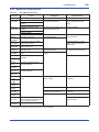
Grounding is always required for the proper
operation of transmitters. Follow the domestic
electrical requirements as regulated in each
country. For a transmitter with a built-in lightning
protector, grounding should satisfy ground
resistance of 10Ω or less.
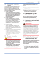
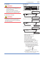
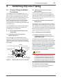
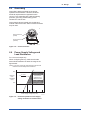
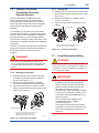
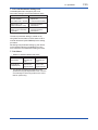
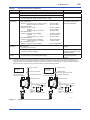
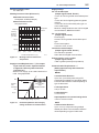
Ground terminals are located on the inside and
outside of the terminal box. Either of these terminals
may be used.
Ground terminal
(inside)
Ground terminal
(outside)
F0611.ai
Figure 6.16 Ground Terminals
6.6 Power Supply Voltage and
Load Resistance
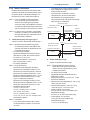
For 4 to 20 mA output only.
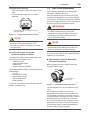
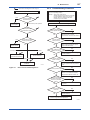
When configuring the loop, make sure that the
external load resistance is within the range in the
figure below.
(Note) In case of an intrinsically safe transmitter, external load
resistance includes safety barrier resistance.
600
External
load
resistance
R (Ω)
R=
E–10.5
0.0244
Communication
applicable range
BRAIN and HART
250
0
10.5
16.6
25.2
Power supply voltage E (V DC)
42
F0612.ai
Figure 6.17 Relationship between Power Supply
Voltage and External Load Resistance
IM 01C25K01-01E