1
USER MANUAL 3RD EDITION Spring 2013 Prepared For:
University of Alabama Huntsville (UAHuntsville)
Department of Electrical & Computer Engineering
301 Sparkman Dr.
Huntsville, AL 35899
Prepared by:
JT Boyd
Ryan Creel
Zachary Dreiling
Grant Paque
John Shirley
This Page Intentionally Left Blank Table of Contents 1 U
Background ....................................................................................................................................... 5 U
U
U
2 Terms of Use ............................................................................................................................................ 5 U
U
2.1 U
Agreement between You and UAHuntsville .................................................................................... 5 U
U
2.2 U
U
Your Obligations ............................................................................................................................... 5 U
U
2.3 U
U
General Disclaimer ............................................................................................................................ 5 U
U
2.4 U
U
Use of Vehicle at Your Own Risk ....................................................................................................... 6 U
U
2.5 U
U
Limitation on Liability ........................................................................................................................ 6 U
U
2.6 U
U
Indemnity .......................................................................................................................................... 6 U
U
2.7 U
U
Third‐Party ........................................................................................................................................ 7 U
U
2.8 U
U
Specific Disclaimer of Warranties ..................................................................................................... 7 U
U
2.9 U
U
Modification ...................................................................................................................................... 8 U
U
U
2.10 Miscellaneous ................................................................................................................................... 8 U
U
U
U
3 Designation of Safety Responsibilities ..................................................................................................... 8 U
U
3.1 U
Individual Safety Responsibilities ...................................................................................................... 8 U
U
3.2 U
U
Group Safety Responsibilities ........................................................................................................... 8 U
U
U
4 Inspection Procedures .............................................................................................................................. 8 U
U
4.1 U
Routine Inspection ............................................................................................................................ 8 U
U
4.2 U
U
Major Buggy Component Recommended Inspection Periods .......................................................... 9 U
U
U
5 Smart Kart Operation ............................................................................................................................... 9 U
U
5.1 U
Operation Guidelines ........................................................................................................................ 9 U
U
5.2 U
U
Health Conditions............................................................................................................................ 10 U
U
5.3 U
U
Operating Procedures ..................................................................................................................... 10 U
U
5.4 U
U
Emergency Procedures ................................................................................................................... 11 U
U
U
6 Safety Devices ........................................................................................................................................ 11 U
U
6.1 U
Description of installed Safety Devices ........................................................................................... 11 U
U
U
6.1.1 Emergency Brake ............................................................................................................................ 11 U
U
U
U
6.1.2 Power/Kill Switch ............................................................................................................................ 11 U
U
U
U
6.1.3 Safety Harness (Seat Belt) ............................................................................................................... 11 U
U
U
U
6.1.4 Fire Extinguisher .............................................................................................................................. 11 U
U
U
U
7 Wiring Diagram ...................................................................................................................................... 12 U
U
8 Software Description .............................................................................................................................. 12 U
U
8.1 U
Brake Transmit ................................................................................................................................ 12 U
U
8.2 U
U
U
8.3 U
Brake Receive .................................................................................................................................. 13 U
U
Throttle Transmit ............................................................................................................................ 14 U
U
8.4 U
U
U
8.5 U
Throttle Receive .............................................................................................................................. 17 U
U
Steering Transmit ............................................................................................................................ 20 U
8.6 U
U
U
U
Steering Receive .............................................................................................................................. 20 U
U
1 Background 1B
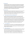
During the spring 2012 semester the Smart Kart project showcased its first prototype for outreach demonstrations. The kart was designed to read signals sent from the gas pedal, steering wheel and brake; then send them wirelessly to the motor, brake, and steering motors. The demonstration will be held during UAHuntsville outreach events. The project is the beginning of a continuing endeavor. The final goal is to have a wireless kart you can control through the internet on a Smartphone or other wireless device, or to have a self driving vehicle that navigates itself using global positioning signals. 2 Terms of Use 0B
Thank you for using the Smart Kart‐UAHuntsville. This page states the terms and conditions under which you may operate our Vehicle, and other information that is or becomes available related to our particular vehicle. By signing our Operations Agreement you accept and agree to be bound, without limitation or qualification by these terms. If you do not accept any of the terms stated here, do not use the vehicle. 1B
2.1 Agreement between You and UAHuntsville 12B
The vehicle is owned and operated by the Electrical and Computer Engineering (ECE) department of The University of Alabama in Huntsville, and is offered to you for use, conditioned on your acceptance without modification of the terms, conditions, disclaimers and notices contained herein. Use of the content, services, and/or products presented constitutes your agreement that you will not use the vehicle for any unlawful purpose and that you will abide by the following terms and conditions and those provided by ECE Dept. of UAHuntsville. This agreement between you and ECE Dept. of UAHuntsville (hereinafter “Agreement”) is effective until terminated by ECE Dept. of UAHuntsville, and may be terminated or changed by ECE Dept. of UAHuntsville at any time without notice. 2B
2.2 Your Obligations 13B
In connection with your use of the vehicle, you shall abide by all applicable federal, state or local laws including those pertaining to such areas as libel, slander, defamation, trade libel, product disparagement, harassment, invasion of privacy, tort, obscenity, indecency and copyright or trademark infringement. 3B
2.3 General Disclaimer 14B
The vehicle is designed to provide users with an enjoyable ride and experience. ECE Dept. of UAHuntsville does not guarantee the accuracy or completeness of any component on the vehicle. As such, ECE Dept. of UAHuntsville will not be responsible for any errors, inaccuracies, omissions or deficiencies in the information provided and the operation of the vehicle. This vehicle is provided “as is,” with no guarantees of completeness, non‐
infringement, accuracy or timeliness, and without warranties of any kind, express or implied. You therefore assume sole responsibility for all risks associated with the use of this vehicle and further accept that ECE Dept. of UAHuntsville is in no way responsible for any consequences whatsoever to anyone arising from your use or interpretation of any information contained within or linked from or to the vehicle. 2.4 Use of Vehicle at Your Own Risk 15B
The Vehicle may contain components and materials from various sources. ECE Dept. of UAHuntsville does not represent or endorse the accuracy or reliability of any materials provided by these sources or any information, data, or analysis derived from these sources. Reliance upon any such information or material shall also be at your own risk. Neither ECE Dept. of UAHuntsville nor its affiliates, partners, officers, directors, employees, subsidiaries, agents or parents shall be liable to you or anyone else for any inaccuracy, error, omission, interruption, timeliness, completeness, defect, failure of performance, computer virus, communication line failure, alteration of, or use of any content herein, regardless of cause, or for any damages resulting there from. 2.5 Limitation on Liability 16B
Under no circumstances shall ECE Dept. of UAHuntsville or any of its affiliates, partners, officers, directors, employees, subsidiaries, agents, or parents be held liable for any damages, whether direct, incidental, indirect, special, or consequential damages, including, without limitation, lost use, data, revenues, time, money, profits or goodwill arising from or in connection with the use, reliance on, or performance of the vehicle, even when ECE Dept. of UAHuntsville has been advised of the possibility of such damages. ECE Dept. of UAHuntsville shall not be liable for damages or injury caused in whole or in part, whether foreseeable or unforeseeable, and whether based in tort (including defamation), contract, and strict liability or otherwise in producing and publishing this vehicle or any materials contained in this vehicle or linked by or to this vehicle. If you are dissatisfied with any of the vehicle’s material or services, or with any of the vehicle’s terms and conditions, your sole and exclusive remedy is to discontinue using the vehicle. 2.6 Indemnity 17B
As a condition of use of the vehicle, you agree to indemnify ECE Dept. of UAHuntsville and its affiliates, partners, officers, directors, employees, subsidiaries, agents, and parents from and against any and all liabilities, expenses (including attorneys’ fees) and damages arising out of any and all claims resulting from your use of the vehicle and the materials (including manuals) thereon, including without limitation any claims alleging facts that if true would constitute a breach by you of these Terms of Use. This indemnity shall include, without limitation, any claim of inaccuracy or defamation based on operating abilities that you use on the vehicle. 2.7 ThirdParty 18B
The vehicle may contain components of third‐party manufacturers. ECE Dept. of UAHuntsville provides these components solely to assist users in operation of the vehicle, other component resources that may be of interest to them and you assume sole responsibility and risk for your use of components to third‐party manufacturer. ECE Dept. of UAHuntsville does not operate or control in any respect any information, content, products or services on such third‐party manufacturers. ECE Dept. of UAHuntsville does not represent or endorse the accuracy or reliability of any of the information, content or advertisements contained on, distributed through, or linked, downloaded or accessed from any of the services contained on these third‐party manufacturers. No reference or link to a third party or a third‐party manufacturer shall constitute an endorsement of such third party or such third‐party manufacturer. 2.8 Specific Disclaimer of Warranties 19B
ALL MATERIALS AND SERVICES ON THIS VEHICVLE, INCLUDING THOSE PROVIDED BY ECE DEPT. OF UAHUNTSVILLE TO THIRD‐PARTY MANUFACTURERS ARE PROVIDED “AS IS” WITHOUT WARRANTY OF ANY KIND. THE CONTENT PUBLISHED ON THIS VEHICLE MAY INCLUDE INACCURACIES OR TYPOGRAPHICAL ERRORS. CHANGES ARE PERIODICALLY MADE TO THE INFORMATION HEREIN. EWBG‐UAH MAKES NO REPRESENTATIONS AND, TO THE FULLEST EXTENT ALLOWED BY LAW, DISCLAIMS ALL WARRANTIES, EXPRESS OR IMPLIED, INCLUDING, BUT NOT LIMITED TO WARRANTIES OF NON‐INFRINGEMENT, MERCHANTABILITY AND FITNESS FOR A PARTICULAR PURPOSE REGARDING THE SUITABILITY OF THE INFORMATION; THE ACCURACY, RELIABILITY, COMPLETENESS OR TIMELINESS OF THE CONTENT, SERVICES, PRODUCTS, GRAPHICS, OR OTHER ITEMS CONTAINED WITHIN THE VEHICLE, OR THE RESULTS OBTAINED FROM ACCESSING AND USING THIS VEHICLE AND/OR THE CONTENT CONTAINED HEREIN. EWBG‐UAH DOES NOT WARRANT THAT THE FUNCTIONS CONTAINED IN THE MATERIALS WILL BE UNINTERRUPTED OR ERROR‐FREE, THAT DEFECTS WILL BE CORRECTED, OR THAT THIS VEHICLE, INCLUDING THE PLACE OF BUISNESS THAT MAKES IT AVAILABLE, ARE FULLY CAPIBLE OF OPERATIONS AND TRAINED IN THE USE OF THE VEHICLE. IN ADDITION, EWBG‐UAH SHALL NOT BE LIABLE TO YOU OR ANYONE ELSE FOR ANY LOSS OR INJURY CAUSED IN WHOLE OR PART BY CONTINGENCIES BEYOND ITS CONTROL IN PROCURING, COMPILING, INTERPRETING, REPORTING OR DELIVERING THE SERVICE AND INFORMATION OF THE VEHICLE AND YOU ASSUME THE ENTIRE COST OF ALL NECESSARY MAINTENANCE, REPAIR OR CORRECTION ARISING FROM ANY SUCH LOSS OR INJURY. 2.9 Modification 20B
ECE Dept. of UAHuntsville shall have the right, at its sole discretion, to make improvements and/or changes in any aspect of the vehicle at any time and does not accept any responsibility for the effects these alterations may have. ECE Dept. of UAHuntsville also reserves the right to change, modify, add or remove terms of this agreement at any time without notice. You agree to review this Agreement periodically since such changes, modifications, additions or deletions shall be effective immediately upon posting and your subsequent use after such posting shall conclusively be deemed to be acceptance by you of such changes, modifications or deletions. 2.10 Miscellaneous 21B
This Agreement shall be deemed to include all other notices, policies, disclaimers, and other terms contained on this vehicle; provided, however, that in the event of a conflict between such other terms and the terms of this Agreement, the terms of this Agreement shall control. This Agreement has been made in and shall be construed and enforced in accordance with Alabama law. Any action to enforce this agreement shall be brought in the federal or state courts located in Alabama. If any provision is deemed to be unlawful or unenforceable, that shall not affect the validity and enforceability of the remaining provisions. 3 Designation of Safety Responsibilities 4B
3.1 Individual Safety Responsibilities 2B
It is each individual’s responsibility to know, and understand the safety rules and regulations associated with the Smart Kart project. As a member of the Design team, every individual must know the status of the project, so they do not put any of the other teammates in harm’s way, or the university. 3.2 Group Safety Responsibilities 23B
It is the group’s responsibility to: •
•
•
•
Develop and maintain a safety program Schedule safety inspections Communicate with group members and advisors concerning safety topics Conduct appropriate training 4 Inspection Procedures 5B
4.1 Routine Inspection 24B
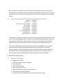
A routine inspection will/ must be done on the Smart Kart. We are all responsible for the safety of the members of the group and any operator of our vehicle. All of the parts of the Smart Kart will be properly inspected before any form of operation. All inspections, maintenance, and testing will be documented for safety and life value of the parts of the Smart Kart. Major components of the kart will have non‐operational inspection periods. 4.2 Major Buggy Component Recommended Inspection Periods 25B
Arduinos:
Bolt & Nuts:
Batteries (if stored uncharged):
Brake System:
Electric Motor:
Fire Extinguisher:
Potentiometers:
Tire (Pressure & Wear):
Steering Motor:
Wire Connections:
2‐3 Months 2‐3 Months 2‐3 Months 2‐3 Months 2‐3 Months 2‐3 Months 2‐3 Months 2‐3 Months 2‐3 Months 2‐3 Months All inspections, maintenance, and testing will be documented for safety and life value of the parts of the wireless buggy. Before all inspections, maintenance and testing the inspector of the component will sign, date, give reason for inspection or maintenance etc. and leave comments for the next inspection or inspector so problems and will be documented. If hazards or potential hazards are found during inspection, maintenance etc. it must be documented in writing and immediately addressed by the group. When a hazard or potential hazards are found and documented the any group member has the authority to halt production on the wireless buggy, for repairs and work will not continue until the proper repairs have been made and a follow‐up inspection has been performed. 5 Smart Kart Operation 6B
5.1 Operation Guidelines 26B
•
•
•
•
•
•
•
•
Weight limit is 250lbs Driver must wear closed toe footwear Secure long hair Secure loose clothing Wear seatbelt at all times Keep hands and feet inside the kart at all times Keep hands on the steering wheel Driver must hold a full drivers license and be over 16 years of age •
•
Drivers are not permitted to drink alcohol prior to operating the kart Drivers are not permitted to eat while operating the kart 5.2 Health Conditions 27B
Those people with the following health conditions should refrain from operating the kart. •
•
•
•
Women that are pregnant, or think they may be pregnant Those with heart conditions Those with serious back problems Those with motion sickness 5.3 Operating Procedures 28B
To start the vehicle: 1. Turn the power switch to ON. a. The power switch is located on the switch box beneath the steering wheel. 2. Verify the ON/OFF Green LED lights up once the power switch is flipped to ON. 3. Wait 10‐15 seconds before operating the vehicle. a. The Arduino/XBee modules are linking to one another during this time. Once the vehicle is started, and the Arduino/XBees have synched up, the kart is ready to drive. To drive the kart forward: 1. Ensure the FORWARD/REVERSE switch is in the forward position. a. The switch is located to the right of the Power Switch b. If the Red LED is not lighted, the kart is working in FORWARD mode 2. Press the Throttle pedal, and away you go. To drive the kart in reverse: 1. Ensure the kart is at a complete stop 2. Flip the FORWARD/REVERSE switch to the reverse position. 3. Ensure the Red LED lights up a. It will take a second to light up i. It is verifying communication to the Arduino that it is ready for reverse operation 4. Press the Throttle pedal, and away you go. To stop the kart: 1. When you are ready to stop the kart, press the brake pedal a. It does not matter if you let off of the throttle pedal or not, because there is a safety feature wired between the brake and throttle Arduinos to kill the throttle signal/power to the drive motor when the brake is applied. 5.4 29B
Emergency Procedures If there is any uncertainty as to the safety of the vehicle/vehicle operations, in expected manner do the following: 1. Pull the emergency brake 2. Flip the power switch to the OFF position 3. Exit the vehicle 6 Safety Devices 7B
6.1 Description of installed Safety Devices 30B
The vehicle has four key safety components that will aid in the safety of the passenger and the vehicle. In designing the vehicle we decided that an emergency brake, kill switch, seat belt, and fire extinguisher were absolute must haves for optimum safety for this vehicle. 6.1.1 Emergency Brake 31B
The emergency brake, often referred to as a hand brake, is positioned on the left hand side of the driver in the vehicle. The emergency brake is easily accessible and is used ONLY in case of brake system failure. Our brake system is a linear actuator connected to the brake system located on the left rear wheel of the vehicle. On the opposite side of the actuator, the emergency brake is connected, and if pulled will effectively and abruptly stop the vehicle. 6.1.2 Power/Kill Switch 32B
The kill switch, often referred to as the dead switch, is positioned under the steering wheel of this vehicle. This switch is also the power switch that you use to turn the vehicle on. When the kill switch is flipped while operational it will discontinue power flow throughout the vehicle. 6.1.3 Safety Harness (Seat Belt) 3B
The seat belt is strictly to protect the passenger, while the vehicle is motion. In the case of an accident, the seat belt, keeps the passenger fastened tightly to the vehicle to prevent the passenger from being thrown out of the vehicle or thrown around in side of the vehicle as well. 6.1.4 Fire Extinguisher 34B
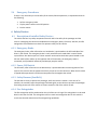
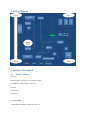
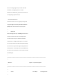
The fire extinguisher will be positioned on the rail of the cart roll cage. The extinguisher is to be used ONLY in the case of a FIRE. The extinguisher will be a multi‐use extinguisher but for this vehicle it must have chemical and electrical fire extinguishing capabilities. 7 Wiring Diagram 8B
9B
8 Software Description 10B
8.1 35B
Brake Transmit //break tx #define breakPin 2 //output pin 2 is renamed to breakPin int potPinB=A0; //assign potPinB to input pin 0 int valB=0; int lastValB=0; void setup() { Serial.begin(9600); pinMode(breakPin,OUTPUT); //digital output (0 or 1) } void loop() { valB=analogRead(potPinB); //read input voltage (0 to 1023) if(valB‐lastValB>15) //break pedal pressed { Serial.println('S'); digitalWrite(breakPin,HIGH); } else if(valB‐lastValB<‐15) //break pedal depressed { Serial.println('R'); digitalWrite(breakPin,LOW); } lastValB=valB; delay(10); } 8.2 36B
Brake Receive //break rx #define PWMbrake 4 //output pin 4 is renamed to PWMbrake #define DIRbrake 2 //output pin 2 is renamed to DIRbrake char c; void setup() { Serial.begin(9600); pinMode(PWMbrake,OUTPUT); //digital output (0 or 1) pinMode(DIRbrake,OUTPUT); //digital output (0 or 1) } void loop() { if(Serial.available()>0) c=Serial.read(); if(c=='S') { digitalWrite(DIRbrake,LOW); digitalWrite(PWMbrake,HIGH); } else if(c=='R') { digitalWrite(DIRbrake,HIGH); digitalWrite(PWMbrake,HIGH); } delay(10); } 8.3 37B
Throttle Transmit //throttle tx int potPinG=A0; //assign potPinG to input pin 0 int switchPin=A1; //assign switchPin to input pin 1 int breakPin=A2; //assign breakPin to input pin 2 int valG=0; int hold=0; //0~500 is low, 501~1023 is high (low=0, high=1000) int op=0; //0~500 is low, 501~1023 is high (low=0, high=1000) int lastop=0; //0~500 is low, 501~1023 is high (low=0, high=1000) void setup() { Serial.begin(9600); } void loop() { hold=analogRead(breakPin); //read in break pin from break tx if(hold>500) hold=1000; else if(hold<=500) hold=0; while(hold>500) { Serial.println('X'); delay(10); hold=analogRead(breakPin); //read again if break is on/off if(hold>500) hold=1000; else if(hold<=500) hold=0; } valG=analogRead(potPinG); //read input voltage (0 to 1023) op=analogRead(switchPin); //read in operation pin if(op>500) op=1000; else if(op<=500) op=0; if(op<lastop&&valG<100) //check forward switch on { Serial.println('Y'); lastop=op; } else if(op>lastop&&valG<100) //check reverse switch on { Serial.println('Z'); lastop=op; } if(valG<100) Serial.println('A'); else if(valG>=100&&valG<200) Serial.println('B'); else if(valG>=200&&valG<300) Serial.println('C'); else if(valG>=300&&valG<400) Serial.println('D'); else if(valG>=400&&valG<500) Serial.println('E'); else if(valG>=500&&valG<600) Serial.println('F'); else if(valG>=600&&valG<700) Serial.println('G'); else if(valG>=700&&valG<800) Serial.println('H'); else if(valG>=800&&valG<900) Serial.println('I'); else if(valG>=900&&valG<1000) Serial.println('J'); else Serial.println('k'); delay(10); } 8.4 38B
Throttle Receive //throttle rx #define PWMgas 3 //output pin 3 is renamed to PWMgas #define DIRgas 2 //output pin 2 is renamed to DIRgas char c; int num=0; void setup() { Serial.begin(9600); pinMode(PWMgas,OUTPUT); //analog output (0 to 255) pinMode(DIRgas,OUTPUT); //digital output (0 or 1) } void loop() { if(Serial.available()>0) c=Serial.read(); if(c=='X') //if break engaged, slow down the motor { while(num>0) { num‐‐; analogWrite(PWMgas,25*num); delay(100); } } if(c=='Y') digitalWrite(DIRgas,LOW); //forward mode else if(c=='Z') digitalWrite(DIRgas,HIGH); //reverse mode if(c=='A') { num=0; analogWrite(PWMgas,0); } else if(c=='B') { num=1; analogWrite(PWMgas,25); } else if(c=='C') { num=2; analogWrite(PWMgas,50); } else if(c=='D') { num=3; analogWrite(PWMgas,75); } else if(c=='E') { num=4; analogWrite(PWMgas,100); } else if(c=='F') { num=5; analogWrite(PWMgas,125); } else if(c=='G') { num=6; analogWrite(PWMgas,150); } else if(c=='H') { num=7; analogWrite(PWMgas,175); } else if(c=='I') { num=8; analogWrite(PWMgas,200); } else if(c=='J') { num=9; analogWrite(PWMgas,225); } else if(c=='K') { num=10; analogWrite(PWMgas,250); } delay(10); } 8.5 39B
Steering Transmit * Description: Transfers our potentiometer values for steering We connect three wires to the Arduino board. The first goes to ground from one of the outer pins of the potentiometer. The second goes from 5 volts to the other outer pin of the potentiometer. The third goes from analog input 2 to the middle pin of the potentiometer. * By turning the shaft of the potentiometer, we change the amount of resistence on either side of the wiper which is connected to the center pin of the potentiometer. This changes the relative "closeness" of that pin to 5 volts and ground, giving us a different analog input. When the shaft is turned all the way in one direction, there are 0 volts going to the pin, and we read 0. When the shaft is turned all the way in the other direction, there are 5 volts going to the pin and we read 1023. In between, analogRead() returns a number between 0 and 1023 that is proportional to the amount of voltage being applied to the pin. * /************************************************************************************ * * Modified: 2/5/2013 * /************************************************************************************ * * Author: Grant Paque' ‐ Lead Programmer * Spring 2013 ECE Smart Kart Team: ////////////////////////////////////// Ryan Creel ‐ Project Manager Zach Dreiling ‐ Robotics & Mechanical Lead John Shirling ‐ Lead Architect, Programmer JT Boyd ‐ Lead Analyst, Architect ////////////////////////////////////// * /***********************************************************************************/ // The potentiometer should be set to the pin 0 // on the arduino int steeringPotPin=A0; // Holds the value of our potentiometer value // read the description above for how that value is found // and how a potentiometer is used with an arduino. double desiredSteeringWheelPotValue=0; void setup() { // Opens our serial port and and sets out baud rate Serial.begin(9600); } void loop() { desiredSteeringWheelPotValue = analogRead(steeringPotPin); //read input voltage (0 to 1023) Serial.println(desiredSteeringWheelPotValue); delay(10); } 8.6 40B
Steering Receive * Description: Receives our potentiometer values for steering from the potentiometer at the steering wheel (see SK_SteeringTX) and uses PID control to fine tune the steering. * Potentiometers: We connect three wires to the Arduino board. The first goes to ground from one of the outer pins of the potentiometer. The second goes from 5 volts to the other outer pin of the potentiometer. The third goes from analog input 2 to the middle pin of the potentiometer. * By turning the shaft of the potentiometer, we change the amount of resistence on either side of the wiper which is connected to the center pin of the potentiometer. This changes the relative "closeness" of that pin to 5 volts and ground, giving us a different analog input. When the shaft is turned all the way in one direction, there are 0 volts going to the pin, and we read 0. When the shaft is turned all the way in the other direction, there are 5 volts going to the pin and we read 1023. In between, analogRead() returns a number between 0 and 1023 that is proportional to the amount of voltage being applied to the pin. * Pulse Width Modulation: Bi‐directional motor control is typically accomplished using an H‐bridge circuit with pulse‐width modulation (PWM) from a microcontroller to vary the speed. * * PID Control With an H‐bridge and a pair of PWM signals the motor is ready for bi‐directional control. The simplest form of control is open loop. This means the controller simply applies a voltage (a PWM signal in this case) but has no way to measure the effect of the applied voltage. The controller simply assumes higher voltage makes the motor go faster. Closed loop control uses feedback from the motor, such as the motor current or speed, to adjust the PWM signal. * /************************************************************************************ * * Modified: 2/5/2013 ‐ Completed 2/24/2013 * /************************************************************************************ * * Author: * Grant Paque' ‐ Lead Programmer Spring 2013 ECE Smart Kart Team: ////////////////////////////////////// Ryan Creel ‐ Project Manager Zach Dreiling ‐ Robotics & Mechanical Lead John Shirling ‐ Lead Architect, Programmer JT Boyd ‐ Lead Analyst, Architect ////////////////////////////////////// * /***********************************************************************************/ #include <PID_v1.h> #define PWMsteer 3 //output pin 3 is renamed to PWMsteer #define DIRsteer 2 //output pin 2 is renamed to DIRsteer int potPinW=A0; //assign potPinW to input pin 0 int valS=‐1; //set to allow Xbee some time to boot up int valW; int steeringDir; //Define Variables we'll be connecting to double Setpoint, Input, Output; // These values are the ticket to making this thing turn correctly // If you don't understand why, please review EE425 for the // coefficients of P, I, and D. // Summary: We want the proportion coefficient to be large because // the vehicle experiences a lot of friction when on the ground, // if you lift the vehicle it will oscillate out of control, this is // because of the constant Kp. The rest of the values are for honing // in on the Setpoint (the value of our steering wheel). double consKp=3, consKi=0.001, consKd=0.045; //Specify the links and initial tuning parameters PID myPID(&Input, &Output, &Setpoint, consKp, consKi, consKd, DIRECT); void setup() { myPID.SetOutputLimits(0,255); //corresponds to our max output for the pin: PWMsteer. Serial.begin(9600); pinMode(PWMsteer, OUTPUT); // analog output (0 to 255) pinMode(DIRsteer, OUTPUT); // digital output (0 or 1) myPID.SetMode(AUTOMATIC); myPID.SetSampleTime(50); // calculate our Output value from PID every 50ms // turn the PID on depending // sometimes this value needs to be higher // on the application, default is 100. } void loop() { valW = analogRead(potPinW); // read our input (ranges from 218‐619(measured)) // we want to match the min and max of our // wheel and steering wheel potentiometers // the numbers below reflect the real values // of the potentiometer but are remapped // to 0 and 255. valW = map(valW, 218, 619, 0, 255); //convert to double for the PID Input = double(valW); /******** Debugging *********/ //Serial.print("Input: "); //Serial.print(Input); //Serial.print(" "); /*****************************/ if(Serial.available()>0) { delay(5); valS = Serial.parseInt(); valS = map(valS, 564, 977, 0, 255); // remap value, same as above Setpoint = double(valS); /******** Debugging *********/ //Serial.print("Setpoint: "); //Serial.print(Setpoint); //Serial.print(" "); /*****************************/ // Below is where the magic happens. We've taken the potentiometer values // which are of a random range and has mostly to do with how they were mounted // and we've remapped the values so that now they represent values from 0 ‐ 255 // for both the steering wheel value and the wheel value. 127 represents the // halfway point where we should be driving directly straight forward. // below handles the 4 cases involved with the steering. // In general, there are 2 sub cases where the calculated error(Setpoint ‐ Input) // is negative and our PID must have positive values for error, therefore we // convert to double // use the .SetControllerDirection() function to reverse the direction so that // when we receive negative values, we will get an output. if(Setpoint >= 127 && Input >= 127) // case 1 { // error = setpoint ‐ input can be positive or negative // we have to handle when our error is negative by reversing // our PID direction if(Setpoint > Input) //case 1a { // our error will always be positive here // and in this case since our Setpoint is greater we want to be turning left myPID.SetControllerDirection(DIRECT); myPID.Compute(); steeringDir = HIGH; digitalWrite(DIRsteer, steeringDir); analogWrite(PWMsteer,Output); } else if(Setpoint < Input) //case 1b { //in this case our error will always be negative //and we want to be turning right myPID.SetControllerDirection(REVERSE); myPID.Compute(); steeringDir = LOW; digitalWrite(DIRsteer, steeringDir); analogWrite(PWMsteer,Output); } } if(Setpoint >= 127 && Input <= 127) //case 2 { //Setpoint will always be greater than the input //so our error will be positive myPID.SetControllerDirection(DIRECT); myPID.Compute(); steeringDir = HIGH; //turning leftward and will eventually hit case 1a digitalWrite(DIRsteer, steeringDir); analogWrite(PWMsteer,Output); } if(Setpoint < 127 && Input < 127) //case 3 { if(Setpoint > Input) //case 3a { //error will be positive and we'll want to be turning left myPID.SetControllerDirection(DIRECT); myPID.Compute(); steeringDir = HIGH; //turning leftward and will eventually hit case 1a digitalWrite(DIRsteer, steeringDir); analogWrite(PWMsteer,Output); } else if(Setpoint < Input) //case 3b { //error will be negative and we'll want to be turning right myPID.SetControllerDirection(REVERSE); myPID.Compute(); steeringDir = LOW; //turning leftward and will eventually hit case 1a digitalWrite(DIRsteer, steeringDir); analogWrite(PWMsteer,Output); } } if(Setpoint < 127 && Input > 127) //case 4 { //we'll want to be turning right and error will always be negative myPID.SetControllerDirection(REVERSE); myPID.Compute(); steeringDir = LOW; //turning right digitalWrite(DIRsteer, steeringDir); analogWrite(PWMsteer,Output); } if(Setpoint == Input) //no error { //our PID has done its job but we'll make sure of it here analogWrite(PWMsteer,0); } } /********* Debugging ************/ //Serial.print("Output: "); //Serial.println(Output); //Serial.print(" "); /*******************************/ delay(10); }