1
TITUS TECHNOLOGICAL LABORATORIES
MLW-1
OPERATIONS MANUAL
TABLE OF CONTENTS
TITLE
INTRODUCTION
INSTALLATION
PROGRAMMING THE MLW-1
REMOTE I/O CONNECTOR
OPERATING THE MLW-1
ALIGNMENT OF THE MLW-1
WARRANTY
SCHEMATICS
SECTION
1
2
3
4
5
6
7
MLW-1
SECTION 1
INTRODUCTION
The TITUS TECHNOLOGICAL LABORATORIES MLW-1 MULTICHANNEL AUDIO CONTROL
was designed to overcome many of the problems associated with stereo broadcasting and
production. Automatic correction of the loss of an audio channel and polarity inversion (out-ofphase audio) as well as automatic insertion of a secondary or tertiary stereo audio source upon
channel loss or silence as well as manual control of these and other conditions are just some of
the features of the MLW-1.
In the automatic mode the microprocessor based MLW-1 operates automatically to correct the
loss of an audio channel by routing the channel with audio into both outputs. It also corrects for
polarity inversion on the inputs by supplying the outputs with a polarity correct signal. This mode
of operation is provided for two of the three stereo inputs. One of the unique features of the
MLW-1 is, when operating in the automatic mode, is the ability to put another source into the air
chain upon loss of a channel after a user selected period of time. The MLW-1 can put another
stereo source into the air chain when silence is detected after a user selected period of time. All
sequencing and time delays are user selected. Another unique feature is a "one - two" bounce
mode. If the MLW-1 is programmed for the "one - two" bounce mode then when the primary
source has a problem (channel loss or silence) a secondary or tertiary source is put into the audio
chain until the problem is rectified. At that point the original or primary source audio is again put
into the audio chain.
In the manual mode the MLW-1 will provide the user manual control over the audio. This provides
the user with: straight pass through audio, polarity inverted (out-of-phase) stereo audio, the sum
of the selected input channels, the difference between the selected input channels, left input or
right input only into both outputs. All of these conditions are provided for two of the three stereo
inputs on the illuminated push button on the front panel or via the remote connector on the rear
panel. The third stereo input is a fixed level input and can not be altered manually.
Full metering is provided on the front panel. Bar graph LED metering is provided for the left and
right channels on a 23 DB range VU meter. Dot graph LED metering is provided for the L+R and
the L-R channels on a 43 DB range VU meter. By using the meters on the front panel it is
possible to perform "on-the-fly" channel balance and polarity measurements of audio source
material. A buffered audio output for Left, Right, L+R and L-R channels is provided on the remote
connector. The metering and monitoring audio follows the active audio source (one or two).
All audio inputs and outputs are through barrier type connections on the rear panel. A "DC-37"
type connector on the rear panel is used for alarm outputs, remote control inputs, and monitor
audio. Audio input channel levels can be dip switch set for nominal operating levels of +8 DBM,
+4 DBM, and -10 DBM. All of the inputs are balanced bridging and D.C. isolated.
The nominal output operating level can be set for either +4 DBM or+8 DBM. The outputs are Xbalanced, D.C. isolated and can provide for a maximum output level of +29 DBV (or greater than
+27 DBM into 600 ohms).
Full remote control of the MLW-1 is provided on a "DC-37" connector on the rear panel. Alarms
are provided for channel loss, silence sense, polarity inversion, and "one - two" bounce mode
active. Outputs are also provided for indicating the current active source as well as the operating
mode of the MLW-1. Control inputs allow operation of the MLW-1 via a remote control or
automation system.
The MLW-1 is completely microprocessor controlled. All audio switching is accomplished with a
32 by 4 microprocessor controlled audio router. The selected audio output is cross faded into the
audio chain by microprocessor controlled VCAs. Front panel switching, remote control, as well as
alarms and status are microprocessor controlled. All user programmed thresholds, sequencing,
and delays are digitally derived. Because of this, the MLW-1 is extremely precise and flexible.
A quick summary of the MLW-1 features follows:
1. Independent level set on each channel of Source 1, Source 2, and Source 3 inputs.
2. Programmable output levels.
3. Microprocessor controlled routing, signal sensing, VCA control.
4. POWER LOSS - AUDIO BYPASS relay puts Source 1 into the outputs if power is lost.
5. Full metering of active source. Full monitoring audio outputs for active source.
6. AUTOMATIC or MANUAL operation. Programmable power up mode selection for
automatic or manual.
7. Automatic Channel Loss correction and Polarity correction (user programmable defeat).
8. Automatic alternate source on Channel Loss or Silence. User programmed SEQUENCE
and TIME DELAYS.
9. Exclusive "ONE - TWO BOUNCE" will put alternate source on line while maintaining watch
on primary source. When problem with primary source is cleared it is put back on line. (User
programmable).
10. Exclusive "ONE - TWO LOOK AHEAD" will not allow secondary source to be put on line if
it has the same problem as the primary source. (User programmable).
11. Alarms for Channel Loss, Polarity inversion, Silence, ONE - TWO BOUNCE.
12. TOTALLY remote controllable. Open collector outputs, TTL control inputs.
13. Substantial head room - +27 dbm, +29 dbv maximum output level.
14. FORCED operating conditions. User can "force" Source 1, Source 2, or Source 3 on line
during automatic operation via remote connector.
MLW-1
SECTION 2
INSTALLATION
After unpacking the MLW-1 check for physical damage to the unit due to shipping. If there is any
problem with the unit please contact the factory immediately and notify the carrier of the damage.
The inputs for the MLW-1 are balanced bridging. Twisted shielded pair wire should be used to
connect to these inputs. The outputs for the MLW-1 are X-balanced. Twisted shielded pair wire
should also be used for connections to the outputs. The wiring configurations for the inputs and
outputs are shown on the "MLW-1 Input and Output wiring diagram" contained in this manual.
The diagram shows how to connect balanced or unbalanced inputs and outputs. The input and
output polarity is marked on the rear panel of the MLW-1. The "+" is the audio "high", the "-" is the
audio "low" and the "S" is the shield of the audio wire. ("S" is not chassis ground but an audio
common).
The MLW-1 is shipped with a +8 DBM input level and a +8 DBM output level. The following
procedure should be followed if the user desires to change the input or output levels:
1. Remove the six 6-32 flat head screws on the sides of the top cover holding it in place. Remove
the five 4-40 screws on the top of the cover. Remove the top cover.
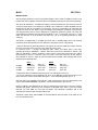
2. Locate the three - 4 position dip switches, SW-1, SW-2, and SW-6. SW-1 is the input
operating level set for "SOURCE 1 - INPUT", SW-2 is for level set for "SOURCE 2 - INPUT", and
SW-6 for "SOURCE 3 - INPUT". Switches 1 and 2 on SW-1 control the input level for the "LEFT"
input channel for source 1. Switches 3 and 4 on SW-1 control the input level for the "RIGHT"
input channel for source 1. Close or open the switches as indicated in the following table for the
expected input operating level.
+8 DBM
+4 DBM
10 DBM
LEFT
SW-1 (1)
closed (on)
closed (on)
open (off)
SW-1 (2)
closed (on)
open (off)
open (off)
RIGHT
SW-1 (3)
closed (on)
closed (on)
open (off)
SW-1 (4)
Closed (on)
open (off)
open (off)
3. Repeat the above procedure for SW-2 for Source 2, and SW-6 for source 3.
4. If the user wants the output operating level to be at +4 DBM then remove the jumper at "CF"
(lower left corner of main circuit board) from pins 1 - 2 and reinstall it between pins 3 - 4.
The next step in the installation of the MLW-1 is the programming of the unit. Please refer to the
section titled "PROGRAMMING THE MLW-1" contained elsewhere in this manual.
NOTE: The MLW-1 was designed for an line input voltage range of 95 VAC to 130 VAC. However
operating the MLW-1 above 120 VAC causes it to generate some heat. If your line voltage
exceeds 120 VAC RMS be sure that the MLW-1 has adequate ventilation and is not
"sandwiched" between other heat generating units.
The MLW-1 draws about 300 MA RMS at 120 VAC RMS or about 36 watts. It can easily be run
from an inexpensive UPS.
MLW-1
SECTION 3
PROGRAMMING THE MLW-1
The MLW-1 allows the user to determine what action is taken when a channel is lost or silence is
detected with the current active source. Only Source 1 and Source 2 are monitored. Source 3 is a
tertiary source and when brought up on line will only reproduce what is on it's inputs. SW-3
controls the sequencing, "Bounce" mode and "Look Ahead" mode, SW-5 controls the time delays
for Channel Loss and Silence Sense while SW-4 controls the Polarity and Channel Loss
checking as well as the Power Up mode.
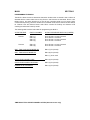
The following table is a brief action table for programming the MLW-1:
ACTIVE SOURCE
SWITCH NUMBER
ACTION / SEQUENCE WHEN ON (CLOSED)
Source 1
SW-3 (1)
SW-3 (2)
SW-3 (3)
SW-3 (4)
Go to Source 2 on loss of channel
Go to Source 2 on silence
Go to Source 3 on loss of channel
Go to Source 3 on silence
Source 2
SW-3 (5)
SW-3 (6)
Go to Source 3 on loss of channel
Go to Source 3 on silence
ONE - TWO LOOK AHEAD MODE ON:
SW-3 (7) On (closed)
ONE - TWO BOUNCE MODE ON:
SW-3 (8) On (closed)
SW-4 (1) is not used
CHECK FOR CHANNEL LOSS:
SW-4 (2) On (closed)
CHECK FOR POLARITY REVERSAL:
SW-4 (3) On (closed)
POWER UP IN AUTOMATIC:
SW-4 (4) On (closed)
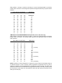
TIME DELAY FOR LOSS OF CHANNEL ACTION (alternate source only)
SW-5 positions 1 through 4 control the time delay in 5 second increments based on the binary
position times 5 seconds. The following table represents the approximate delay for specific switch
positions:
SW-5 SWITCH POSITIONS
(1)
(2)
(3)
(4)
off
on
off
on
off
on
off
on
off
on
off
on
off
on
off
on
off
off
on
on
off
off
on
on
off
off
on
on
off
off
on
on
off
off
off
off
on
on
on
on
off
off
off
off
on
on
on
on
off
off
off
off
off
off
off
off
on
on
on
on
on
on
on
on
TIME DELAY
(SECONDS)
IMMEDIATE
5
10
15
20
25
30
35
40
45
50
55
60
65
70
75
TIME DELAY FOR SILENCE SENSE ACTION (alternate source and alarm only)
SW-5 positions 5 through 8 control the time delay in 15 second increments based on the binary
position times 15 seconds. The following table represents the approximate delay for specific
switch positions:
SW-5 SWITCH POSITIONS
(5)
(6)
(7)
(8)
off
on
off
on
off
on
off
on
off
on
off
on
off
on
off
on
off
off
on
on
off
off
on
on
off
off
on
on
off
off
on
on
off
off
off
off
on
on
on
on
off
off
off
off
on
on
on
on
off
off
off
off
off
off
off
off
on
on
on
on
on
on
on
on
TIME DELAY
(SECONDS)
15
30
45
60
75
90
105
120
135
150
165
180
195
210
225
240
(1 minute)
(2 minutes)
(3 minutes)
(4 minutes)
NOTE: The MLW-1 is factory shipped for no sequence on loss of channel (it will always bring up
an alternate channel on loss of channel unless programmed for alternate source on loss of
channel). The MLW-1 is also programmed for no sequence on silence sense. The MLW-1 will
always alarm after silence is sensed after the programmed time delay. This delay is factory preset
for 60 seconds. In other words, all of the switches on SW-3 are open (off) and only SW-5 (5) and
SW-5 (6) are closed (on).
Additionally SW-4 (2), (3), (4) are closed (on) for checking Channel Loss, Polarity, and powering
up in Automatic.With normal audio on the source inputs there is a natural delay of about 1
second before the MLW-1 will recgonize loss of channel even in the “immediate mode”. Polarity
takes about two seconds to recgonize polarity inversion or recovery from polarity error.
The following is a list of the specific actions of each of the programming functions by switch
position number:
SW-3 (1) GO TO SOURCE 2 ON LOSS OF CHANNEL ON SOURCE 1 Normally the MLW-1 will
bring up the channel with audio into both outputs when a channel is lost. Switching this switch to
the "ON" position enables the function of going to source 2 with the loss of a channel. The result
is that the MLW-1 will switch it's output audio from source 1 to source 2 (as well as the
metering and detector circuits). Source 2 becomes the primary source. There is a time delay
associated with this function. The time delay is set by SW-5 (1-4). If the time delay is set for
immediate response then the MLW-1 will not bring up the alternate channel but bring up source 2
immediately. (See "ONE -TWO" bounce below for variations).*
SW 3 (2) GO TO SOURCE 2 ON SILENCE SENSE ON SOURCE 1 The MLW-1 always alarms
on silence after the time delay set by SW-5 (5-8). If this switch is put in the "ON" position then the
MLW-1 will switch it's output audio from source 1 to source 2 (as well as the metering and
detector circuits) after the time delay set by SW-5 (5-8). Source 2 becomes the primary source.
(See "ONE - TWO" bounce below for variations).*
SW-3 (3) GO TO SOURCE 3 ON LOSS OF CHANNEL ON SOURCE 1 Normally the MLW-1 will
bring up the channel with audio into both outputs when a channel is lost. Switching this switch to
the "ON" position enables the function of going to source 3 with the loss of a channel. The result
is that the MLW-1 will switch it's output audio from source 1 to source 3. There is a time delay
associated with this function. The time delay is set by SW-5 (1-4). If the time delay is set for
immediate response then the MLW-1 will not bring up the alternate channel but bring up source 3
immediately. The metering and detector circuits stay on source 1 waiting for the return of the lost
channel. As soon as the channel returns then the MLW-1 will return it's outputs to source 1.
SW-3 (4) GO TO SOURCE 3 ON SILENCE SENSE ON SOURCE 1 The MLW-1 always alarms
on silence after the time delay set by SW-5 (5-8). If this switch is put in the "ON" position then the
MLW-1 will switch it's output audio from source 1 to source 3 after the time delay set by SW-5 (58). The metering and detector circuits stay on source 1 waiting for the return of audio on source
1. As soon as the audio returns then the MLW-1 will return it's outputs to source 1.
SW-3 (5) GO TO SOURCE 3 ON LOSS OF CHANNEL ON SOURCE 2 Normally the MLW-1 will
bring up the channel with audio into both outputs when a channel is lost. Switching this switch to
the "ON" position enables the function of going to source 3 with the loss of a channel. The result
is that the MLW-1 will switch it's output audio from source 2 to source 3. There is a time delay
associated with this function. The time delay is set by SW-5 (1-4). If the time delay is set for
immediate response then the MLW-1 will not bring up the alternate channel but bring up source 3
immediately. The metering and detector circuits stay on source 2 waiting for the return of the lost
channel. As soon as the channel returns then the MLW-1 will return it's outputs to source 2.
SW-3 (6) GO TO SOURCE 3 ON SILENCE SENSE ON SOURCE 2 The MLW-1 always alarms
on silence after the time delay set by SW-5 (5-8). If this switch is put in the "ON" position then the
MLW-1 will switch it's output audio from source 2 to source 3 after the time delay set by SW-5 (58). The metering and detector circuits stay on source 2 waiting for the return of audio on source
2. As soon as the audio returns then the MLW-1 will return it's outputs to source 2.
SW-3 (7) ONE - TWO LOOK AHEAD MODE This is one of the unique features of the MLW-1.
With this switch in the "ON" position the MLW-1, when programmed to bring up source 2 (source
1 active) with channel loss or silence sense on source 1, will keep the MLW-1 on source 1 if
source 2 has the identical problem. This will keep the MLW-1 from switching to the alternate
source if the problem with source 1 is, for example, at the studio and not on the STL that the
MLW-1 is protecting. This feature is handy for STLs. With this switch in the "OFF" position then
the MLW-1 will switch to source 2 regardless of the condition of source 2. This condition would
be desirable if the MLW-1 is being used as a studio or remote broadcast switcher.
SW-3 (8) ONE - TWO BOUNCE MODE This is another one of the unique features of the MLW-1.
With this switch in the "ON" position the MLW-1, when programmed to bring up source 2 (source
1 active) when channel loss or silence sense occurs, will keep the detector circuits on source 1
while putting the audio from source 2 into it's outputs. When the error condition that caused
source 2 to be put into the outputs is corrected then the MLW-1 will automatically return the
outputs to source 1. In effect, the audio will "bounce" from source 1 to source 2 (if so
programmed on error) while the detectors stay on source 1. If a time delay is selected for the
function then the ONE - TWO bounce will wait for that delay before performing this function. This
function will work in "tandom" with the "ONE - TWO LOOK AHEAD" feature above. If the "ONE TWO LOOK AHEAD" is enabled the "ONE - TWO BOUNCE" will not transfer sources if source 2
has the same problem as source 1.
SW-5 (5-8) TIME DELAY SET FOR SILENCE SENSE ACTION See table for settings. The
"WARN" alarm on the front panel and the remote "SILENCE SENSE" alarm will always alarm
after the time delay with silence on the "primary" source regardless of the programming on SW-3
(2, 4, or 6).
The levels at which Loss of Channel and Silence are detected are determined by the settings of
R246, R257, R266, and R273. To change these operating parameters turn to the section in this
manual titled "ALIGNMENT OF THE MLW-1".
* NOTE: Unless operating in the "ONE - TWO bounce" mode, operating with source 1 active and
either SW-3 (1) (GO TO Source 2 on Loss of Channel) or SW-3 (2) (GO TO Source 2 on Silence
Sense) switches "ON" source 2 will become the "primary" source when an error occurs. The only
way to put source 1 on again is to put the unit into the MANUAL MODE, and push the "Source 1"
button. Alternately if operating in the AUTOMATIC MODE then the MLW-1 can be put back into
source 1 via the remote connector and a "FORCED SOURCE 1" command issued. (See
REMOTE I/O for further details).
SPECIAL SILENCE MODES
SILENCE CASCADE: With SW-3 programmed for Source 1 to go to Source 2 with silence and
Source 1 to go to Source 3 with silence and Source 2 programmed to go to Source 3 with silence
(SW-3 switches 2,4, and 6 ON) the following sequence will happen:
ONE-TWO LOOK AHEAD OFF, ONE-TWO BOUNCE OFF:When silence occurs on Source 1 the
MLW-1 will transfer to Source 2 after the programmed time delay. If Source 2 is also silent then
the MLW-1 will wait for the time delay again then bring up Source 3. When audio returns to
Source 2, the MLW-1 will check for audio on Source 1. If Source 1 also has audio then the MLW1 will transfer back to Source 1 from Source 3.
ONE-TWO LOOK AHEAD ON, ON-TWO BOUNCE OFF:When silence occurs on Source 1 the
MLW-1 will wait for the time delay then look at Source 2 for audio. If there is no audio on Source
2 then the MLW-1 will transfer to Source 3 and wait for audio to return to Source 1 or Source 2.
As soon as audio returns to Source 1 or 2 then the MLW-1 will transfer back to Source 1 or 2
(which ever is active). If Source 2 has audio when Source 1 was initially silent then the MLW-1
will transfer to Source 2.
ONE-TWO LOOK AHEAD OFF OR ON, ON-TWO BOUNCE ON:When silence occurs on Source
1 the MLW-1 will put Source 2 on regardless if there is audio present on Source 2 or not. The
MLW-1 will then wait for audio to return on Source 1. When audio reappears on Source 1 the
MLW-1 will transfer back to Source 1.
ALWAYS TEST THE MLW-1 PROGRAMMING BEFORE PUTTING
IT ON LINE!
(VERSION 2.07+)
MLW-1
SECTION 4
REMOTE I/O CONNECTOR
All of the features of the MLW-1 are available through the REMOTE I/O connector as well as
quite a few additional items. To control the MLW-1 a relay (or other dry closure), TTL level
device, or open collector device is all that is needed. The remote control inputs to the MLW-1 are
TTL with internal pull up resistors. Care should be taken not to exceed + 5 VDC on these inputs.
Proper shielding is necessary and short runs of wire are recommended.
The ALARM outputs from the MLW-1 are open collector and are capible of driving up to 500 ma
at 50 volts MAXIMUM. If the alarm outputs are to drive an inductive load (relay) a supression
diode is required across the load to inhibit spikes from entering the MLW-1. The LED indicator
group is a TTL level output and should not be loaded by more than 16 ma. A remote control of
current design can be directly driven as well as LEDs and logic circuitry. For other loads, insert a
transistor capible of driving the required load.
The MLW-1 also has four audio outputs. These are for the active source (Source 1 or Source 2)
and are unbalanced. The output level is approximately 1 volt P-P at "0 VU". The outputs are for
Left Channel, Right Channel, L + R, and L - R. These outputs are buffered and can drive most
audio amplifiers directly.
The following pages in this section describe the REMOTE I/O in detail.REMOTE I/O PINOUT
PIN #
1
2
3
4
5
6
7
8
9
10
11
12
13
14
15
16
17
18
19
FUNCTION
Analog Common
Analog Common
Analog Common
Analog Common
Analog Common
Analog Common
Digital Common
Input Auto/Manual (A,M)
Input Source 3 on (A,M)
Input Source 2 on (A,M)
Input Source 1 on (A,M)
Input (Reserved)
Input STEREO FREEZE (A)
Output LED L,R/L,-R *
Output LED Group Indicator*
Output Auto/Manual
Output Source 3 active
Output Source 2 active
Output Source 1 active
A = Automatic mode control only
Manual mode control
20
21
22
23
24
25
29
30
PIN #
FUNCTION
L - R Audio Out
L + R Audio Out
Right Channel Audio Out
Left Channel Audio Out
+5 VDC Current Limited
+5 VDC Current Limited
26
Input right channel on (M)
27
Input left channel on (M)
28
Input L - R on (M)
Input L + R on (M)
Input L,-R on (M)
31
Input L,R on (M)
32
Output LED R/L-R *
33
Output LED L/L+R *
34
Output Bounce Mode Active
35
Output POLARITY ALARM
36
Output SILENCE ALARM
37
Output CHANNEL LOSS ALARM
M= Manual mode control onlyA,M = Either Automatic or
* LED channel output indicators are encoded using the following table:
PIN 15
PIN 14
PIN 33
PIN 32
LOW
L,R
Left
Right
HIGH
L,-R
L+R
L-R
Pins 14, 33, and 32 are active HIGH TTL outputs and correspond to the level of PIN 15. Only one
output (pin 14, 33, or 32) will be active at any given time.
The following is a complete description of the function of each of the REMOTE I/O pins in
numerical order:
PIN 1 - Analog common (used for the buffered audio outputs only)
PIN 2 - Analog common
PIN 3 - Analog common
PIN 4 - Analog common
PIN 5 - Analog common
PIN 6 - Analog common
PIN 7 - Digital common (used for digital input and outputs only)
PIN 8 - Auto/Manual. This input is used to remotely put the MLW-1 into Manual if it is in
Automatic, and into Automatic if it is in Manual. Connect to pin 7 to activate.
PIN 9 - Source 3 On. This input is used in either the Manual or Automatic mode to put Source 3
on. Because of this, Source 3 can "override" either Source 1 or Source 2 in the Automatic mode.
This may be usefull if it is necessary to put a stereo synthesizer or test signal on the air quickly.
Connect to pin 7 to activate.
PIN 10 - Source 2 On. This input is used to put Source 2 on remotely when in the Automatic or
Manual mode. Connect to pin 7 to activate.
PIN 11 - Source 1 On. This input is used to put Source 1 on remotely when in the Automatic or
Manual mode. Connect to pin 7 to activate.
PIN 12 - Reserved. This pin is used for custom user remote conditions.
PIN 13 - STEREO FREEZE. This input will "FREEZE" the MLW-1 in the L,R or "stereo" mode
during operation in the Automatic mode. During operation in this mode the MLW-1 will not check
polarity, silence sense, or channel loss. The MLW-1 will freeze after the next transision if it is
operating in any condition other than L,R. Connect to pin 7 to activate.
PIN 14 - LED output word (L,R / L,-R). The six operating conditions of the MLW-1 as indicated on
the front panel are encoded into four outputs. These outputs work in two groups. The first group
is indicated by a LOW on pin 15 and the second group is indicated by a HIGH on pin 15. This
output is TTL level and caution is advised with respect to interfacing these output in this group.
This pin indicates L,R is active with pin 15 low and L,-R active with pin 15 high.
PIN 15 - LED Group Indicator. See pin 14 above for description of this pin
PIN 16 - AUTO/MANUAL Output. This pin is an open collector output that indicates the current
status of the MLW-1. A "LOW" indicates that the MLW-1 is operating in the Automatic mode. Use
pin 7 for the common. The maximum load is 500 ma at 50 volts. A suppression diode is
recommended across the load if it is inductive such as a relay.
PIN 17 - Source 3 On. This pin is an open collector output that indicates the current source on the
MLW-1. A "LOW" indicates that the MLW-1 is operating with Source 3 on. Use pin 7 for the
common. The maximum load is 500 ma at 50 volts. A suppression diode is recommended across
the load if it is inductive such as a relay.
PIN 18 - Source 2 On. This pin is an open collector output that indicates the current source on the
MLW-1. A "LOW" indicates that the MLW-1 is operating with Source 2 on. Use pin 7 for the
common. The maximum load is 500 ma at 50 volts. A suppression diode is recommended across
the load if it is inductive such as a relay.
PIN 19 - Source 1 On. This pin is an open collector output that indicates the current source on the
MLW-1. A "LOW" indicates that the MLW-1 is operating with Source 1 on. Use pin 7 for the
common. The maximum load is 500 ma at 50 volts. A suppression diode is recommended across
the load if it is inductive such as a relay.
PIN 20 - Monitor Audio Out L - R. This output is used for monitoring the current source (Source 1
or Source 2) operating on the MLW-1. The level on this pin is approximately 1 volt P-P when the
meter indicates "0 VU". This output is unbalanced. Use any of pins 1 through 6 or pin 24 for the
common.
PIN 21 - Monitor Audio Out L + R. This output is used for monitoring the current source (Source 1
or Source 2) operating on the MLW-1. The level on this pin is approximately 1 volt P-P when the
meter indicates "0 VU". This output is unbalanced. Use any of pins 1 through 6 for the common.
PIN 22 - Monitor Audio Out RIGHT. This output is used for monitoring the current source (Source
1 or Source 2) operating on the MLW-1. The level on this pin is approximately 1 volt P-P when
the meter indicates "0 VU". This output is unbalanced. Use any of pins 1 through 6 or pin 24 for
the common.
PIN 23 - Monitor Audio Out LEFT. This output is used for monitoring the current source (Source 1
or Source 2) operating on the MLW-1. The level on this pin is approximately 1 volt P-P when the
meter indicates "0 VU". This output is unbalanced. Use any of pins 1 through 6 or pin 24 for the
common.
PIN 24 - +5 VDC Current limited 5 volt output source for external relays and leds.
PIN 25 - +5 VDC Current limited 5 volt output source for external relays and leds.
PIN 26 - PUT RIGHT CHANNEL ON. This input will, when the MLW-1 is in the Manual mode, put
the Right channel of the current source (Source 1 or Source 2) into both outputs. Connect to pin 7
to activate.
PIN 27 - PUT LEFT CHANNEL ON. This input will, when the MLW-1 is in the Manual mode, put
the Left channel of the current source (Source 1 or Source 2) into both outputs. Connect to pin 7
to activate.
PIN 28 - PUT L - R ON. This input will, when the MLW-1 is in the Manual mode, put the
DIFFERENCE between the input channels of the current source (Source 1 or Source 2) into both
outputs. Connect to pin 7 to activate.
PIN 29 - PUT L + R ON. This input will, when the MLW-1 is in the Manual mode, put the SUM of
the input channels of the current source (Source 1 or Source 2) into both outputs. Connect to pin
7 to activate.
PIN 30 - PUT L,-R ON. This input will, when the MLW-1 is in the Manual mode, POLARITY
INVERTE the input channels of the current source (Source 1 or Source 2) into both outputs.
Connect to pin 7 to activate.
PIN 31 - PUT L,R ON. This input will, when the MLW-1 is in the Manual mode, put the input
channels of the current source (Source 1 or Source 2) into both outputs. Connect to pin 7 to
activate.
PIN 32 - LED output word (R / L-R). The six operating conditions of the MLW-1 as indicated on
the front panel are encoded into four outputs. These outputs work in two groups. The first group
is indicated by a LOW on pin 15 and the second group is indicated by a HIGH on pin 15. The
output level is TTL level and caution is advised with respect to interfacing the outputs in this
group. This pin indicates RIGHT is active with pin 15 low and L-R active with pin 15 high.
PIN 33 - LED output word (L / L+R). The six operating conditions of the MLW-1 as indicated on
the front panel are encoded into four outputs. These outputs work in two groups. The first group
is indicated by a LOW on pin 15 and the second group is indicated by a HIGH on pin 15. The
output level is TTL level and caution is advised with respect to interfacing the outputs in this
group. This pin indicates LEFT is active with pin 15 low and L+R active with pin 15 high.
PIN 34 - BOUNCE MODE ACTIVE. This pin is an open collector output that indicates that the
BOUNCE mode is active on the MLW-1. The BOUNCE mode is indicated when the MLW-1 is
programmed for the "ONE - TWO BOUNCE" and a condition exists to put the MLW-1 into that
mode, or when the MLW-1 is programmed to go to Source 3 with error condition and a condition
exists to put the current source at Source 3. This indicator is only active during operation in the
Automatic mode. A "LOW" indicates that the MLW-1 is operating with the BOUNCE mode on.
Use pin 7 for the common. The maximum load is 500 ma at 50 volts. A suppression diode is
recommended across the load if it is inductive such as a relay.
PIN 35 - POLARITY ALARM. This pin is an open collector output that indicates that the MLW-1
has discovered that the source is out-of-phase and has corrected the problem. A "LOW" indicates
that the MLW-1 is operating with the L,-R mode on. Use pin 7 for the common. The maximum
load is 500 ma at 50 volts. A suppression diode is recommended across the load if it is inductive
such as a relay.
PIN 36 - SILENCE SENSE ALARM. This pin is an open collector output that indicates that the
MLW-1 has discovered that the source is silent after the preprogrammed period of time delay. A
"LOW" indicates that the MLW-1 has detected silence. Use pin 7 for the common. The maximum
load is 500 ma at 50 volts. A suppression diode is recommended across the load if it is inductive
such as a relay.
PIN 37 - CHANNEL LOSS ALARM. This pin is an open collector output that indicates that the
MLW-1 has discovered that there is a missing channel on the current source (Source 1 or Source
2). A "LOW" indicates that the MLW-1 has detected a lost channel and has put the channel with
audio into both of it's outputs. Use pin 7 for the common. The maximum load is 500 ma at 50
volts. A suppression diode is recommended across the load if it is inductive such as a relay.
MLW-1
SECTON 5
OPERATING THE MLW-1
After properly installing and setting up the MLW-1, operation is quite simple. The push buttons
will illuminate to indicate what is happening to the audio and what the MLW-1 is doing.
AUTOMATIC MODE
When the MLW-1 is first powered up it will either start in the Automatic or Manual mode
depending on how the user has pre-programmed it. In the Automatic mode (the button labeled
"AUTO/MAN" is illuminated) pushing any of the other buttons will have no effect and are "locked
out". What the user has programmed the MLW-1 to do with channel or signal loss is now in
effect. The MLW-1 initializes with Source 1 as the active input, and will reproduce the source
(pass through) as indicated by the "L,R" LED being lit.
There are four overrides to the Automatic mode. They are: Source 1 ON, Source 2 On, Source 3
ON, and Stereo Freeze. These three are available on the Remote I/O connector on the rear of the
MLW-1 and are described in the section of this manual titled "Remote I/O Connector".
As mentioned earlier, the push buttons illuminate to indicate what the MLW-1 is doing. The
following describes the cause and effect of various automatic functions:
SOURCE 1 ACTIVE
LOSS OF CHANNEL - NO PROGRAMMING The MLW-1 will automatically bring up the alternate
channel into both outputs. The LEDs will indicate the channel that has audio (L or R) and the
WARN LED will light.
LOSS OF CHANNEL - GO TO SOURCE 2 - NO DELAY The MLW-1 will immediately bring up
Source 2 into the outputs. The L,R LED will light. The WARN LED will not light. All monitoring is
transferred to Source 2.
LOSS OF CHANNEL - GO TO SOURCE 2 - WITH DELAY The MLW-1 will bring up the alternate
channel into both outputs then wait for the programmed delay time to elapse. The LEDs will
indicate the channel that has audio (L or R) and the WARN LED will light. After the delay, and
with no audio detected on the missing channel, the MLW-1 will switch to Source 2.
LOSS OF CHANNEL - GO TO SOURCE 2 - ONE/TWO BOUNCE Depending on the delay, the
MLW-1 will transfer the outputs to Source 2. The metering and detectors stay on Source 1. The
LEDs will light steady for L,R and Source 2. The LEDs will blink for the missing channel on
Source 1 (L or R), and the Source 1 LED will blink. The blinking serves two functions. The first
indicates that the ONE-TWO BOUNCE mode is active (as programmed internally) and that
Source 1 is missing a channel and which channel is missing. As soon as the channel is restored,
the MLW-1 will bring up Source 1.
LOSS OF CHANNEL - GO TO SOURCE 3 - NO DELAY The MLW-1 will immediately bring up
Source 3 into the outputs. The missing channel LED (L or R) will blink as will the Source 1 LED.
The WARN LED will light. As soon as audio is restored to the missing channel on Source 1 it will
be put back into the outputs. This function is like the ONE/TWO BOUNCE mode, but is not user
programmed.
LOSS OF CHANNEL - GO TO SOURCE 3 - WITH DELAY The MLW-1 will bring up the alternate
channel into both outputs then wait for the programmed delay time to elapse. The LEDs will
indicate the channel that has audio (L or R) and the WARN LED will light. After the delay, and
with no audio detected on the missing channel, the MLW-1 will switch to Source 3. The metering
stays on Source 1. As soon as audio is restored to the missing channel on Source 1 it will be put
back into the outputs. This function is like the ONE/TWO BOUNCE mode, but is not user
programmed.
SILENCE - NO SEQUENCE PROGRAMMING With silence and after the programmed time delay
the WARN LED will light.
SILENCE - GO TO SOURCE 2 With silence and after the programmed time delay the MLW-1 will
transfer the outputs to Source 2. Metering and the detectors are also transferred. Since this is a
total change over of audio, metering, and control there is no WARN LED.
SILENCE - GO TO SOURCE 2 - ONE/TWO BOUNCE Depending on the delay, the MLW-1 will
transfer the outputs to Source 2. The metering and detectors stay on Source 1. The LED will light
steady for Source 2. The WARN LED will light. The L,R LED and the Source 1 LED will blink. The
blinking serves two functions. The first indicates that the ONE-TWO BOUNCE mode is active (as
programmed internally) and that Source 1 is missing. As soon as the audio is restored the MLW-1
will bring up Source 1.
SILENCE - GO TO SOURCE 3 Depending on the delay, the MLW-1 will transfer the outputs to
Source 3. The metering and detectors stay on Source 1. The WARN LED will light. The L,R LED
and the Source 1 LED will blink. The blinking serves two functions. The first indicates that the
ONE-TWO BOUNCE mode is active (as programmed internally) and that Source 1 is missing. As
soon as the audio is restored, the MLW-1 will bring up Source 1.
SILENCE CASCADE: With SW-3 programmed for Source 1 to go to Source 2 with silence and
Source 1 to go to Source 3 with silence and Source 2 programmed to go to Source 3 with silence
(SW-3 switches 2, 4, and 6 ON) the following
sequence will happen:
ONE-TWO LOOK AHEAD OFF, ONE-TWO BOUNCE OFF:When silence occurs on Source 1 the
MLW-1 will transfer to Source 2 after the programmed time delay. If Source 2 is also silent then
the MLW-1 will wait for the time delay again then bring up Source 3. When audio returns to
Source 2, the MLW-1 will check for audio on Source 1. IfSource 1 also has audio then the MLW1 will transfer back to Source 1 from Source 3.
ONE-TWO LOOK AHEAD ON, ONE-TWO BOUNCE OFF:When silence occurs on Source 1 the
MLW-1 will wait for the time delay then look at Source 2 for audio. If there is no audio on Source
2 then the MLW-1 will transfer to Source 3 and wait for audio to return to Source 1. As soon as
audio returns to Source 1 then the MLW-1 will transfer back to Source 1. (Source 2 will not be
activated). If Source 2 has audio when Source 1 was initially silent then the MLW-1 will transfer to
Source 2.
ONE-TWO LOOK AHEAD OFF OR ON, ONE-TWO BOUNCE ON:When silence occurs on
Source 1 the MLW-1 will put Source 2 on regardless if there is audio present on Source 2 or not.
The MLW-1 will then wait for audio to return on Source 1. When audio reappears on Source 1 the
MLW-1 will transfer back to Source 1.
SOURCE 2 ACTIVE
LOSS OF CHANNEL - NO PROGRAMMING The MLW-1 will automatically bring up the alternate
channel into both outputs. The LEDs will indicate the channel that has audio (L or R) and the
WARN LED will light.
LOSS OF CHANNEL - GO TO SOURCE 3 - NO DELAY The MLW-1 will immediately bring up
Source 3 into the outputs. The missing channel LED (L or R) will blink as will the Source 2 LED.
The WARN LED will light. As soon as audio is restored to the missing channel on Source 2 it will
be put back into the outputs. This function is like the ONE/TWO BOUNCE mode, but is not user
programmed.
LOSS OF CHANNEL - GO TO SOURCE 3 - WITH DELAY The MLW-1 will bring up the alternate
channel into both outputs then wait for the programmed delay time to elapse. The LEDs will
indicate the channel that has audio (L or R) and the WARN LED will light. After the delay, and
with no audio detected on the missing channel, the MLW-1 will switch to Source 3. The metering
stays on Source 2. As soon as audio is restored to the missing channel on Source 2 it will be put
back into the outputs. This function is like the ONE/TWO BOUNCE mode, but is not user
programmed.
SILENCE - NO SEQUENCE PROGRAMMING With silence and after the programmed time delay
the WARN LED will light.
SILENCE - GO TO SOURCE 3 Depending on the delay, the MLW-1 will transfer the outputs to
Source 3. The metering and detectors stay on Source 2. The WARN LED will light. The L,R LED
and the Source 2 LED will blink. The blinking serves two functions. The first indicates that the
ONE-TWO BOUNCE mode is active (as programmed internally) and that Source 2 is missing. As
soon as the audio is restored, the MLW-1 will bring up Source 2. (See also SILENCE
CASCADE).
OPERATING IN THE MANUAL MODE
To put the MLW-1 into the Manual mode, push the button labeled "AUTO/MAN". When in the
Manual mode the "AUTO/MAN" light will not be illuminated. To return to the Automatic mode
simply push the "AUTO/MAN" button again. When illuminated the MLW-1 is in the Automatic
mode.
In the Manual mode the MLW-1 provides the user with six modes of operation on either Source 1
or Source 2. The MLW-1 will reproduce the stereo input, produce an out-of-phase stereo source,
produce the sum of the inputs on both output channels, produce the difference between the two
channels on both outputs, direct the left or right channels inputs to both outputs. Source 3 can
also be accessed by the front panel but will only reproduce the source unmodified. One unique
feature of the MLW-1 is that it will remember the last condition for the last active source. In other
words, if Left channel was selected for Source 1 and L+R selected for Source 2 then simply
pushing the Source 1 button will recall Left channel (Source 1) and pushing the Source 2 button
will recall L+R for Source 2. This makes "A/B" comparisons between two sources very easy.
Metering follows the active source except when Source 3 is called. Then the metering stays on
the last active of Source 1 or Source 2. Under some conditions there is a slight delay in switching
the metering and audio, typically under 500 MS.
Source 3 is accessed by pushing BOTH the Source 1 and the Source 2 buttons and releasing
them. The lights for Source 1 and Source 2 will both light. No other condition will be lighted. To
return to either Source 1 or Source 2 just push their respective buttons. The last condition for that
source will again be active.
When operating in the Manual mode and Source 3 is active the MLW-1 will not allow returning to
the Automatic mode. The MLW-1 must have a preset source (either Source 1 or Source 2) before
it can change from Manual to Automatic mode.
The WARN LED will never light during the Manual mode. The MLW-1 assumes that the operator
is in control and no alarms are necessary.
MLW-1
SECTION 6
ALIGNMENT OF THE MLW-1
The MLW-1 was carefully adjusted at the factory for operation under normal conditions. However,
replacement of parts or modification of operating parameters will require some degree of recalibration
There is one basic alignment procedure. However, if you are only changing the operating level of the
LOSS OF CHANNEL detectors then skip to the section on DETECTOR ALIGNMENT.
BASIC TEST EQUIPMENT REQUIRED:
4-1/2 digit DVM (FLUKE 8060A)
Audio oscillator with less than 0.03 THD (Sound Technology 1710A)
Oscilloscope (Dual trace - 100 mHz)
Distortion analyzer (Sound Technology 1710A)
Precision 600.0 ohm resistor networks
BASIC INITIAL SETUP
Remove the eleven cover screws and take the top cover of the unit off. Refer to the layout print for
the MLW-1 for all of the following adjustments. (In the following adjustments +8.0 DBM is equivalent to
1.946 Volts RMS across 600.0 ohms at 400 Hz)
1. Connect the 600.0 ohm resistor to the audio oscillator output. Connect the "HIGH" of the oscillator
to the "+" terminal of the LEFT and RIGHT channel inputs of Source 1. Connect the "LOW" of the
oscillator to the "-" terminal of the LEFT and RIGHT channel inputs of Source 1. The inputs are now fed
in phase. Plug in the MLW-1 and depress the AUTO/MANUAL button to place the MLW-1 into the
MANUAL mode. Depress the L,R button (first button on left).
2. Connect a 600.0 ohm resistor across the audio analyzer inputs and connect the "HIGH" input to the
LEFT channel output "+", and the "LOW" input to "-" of the LEFT channel output. Adjust the audio
oscillator for exactly +8.0 DBM at 400 Hz.
3. Set all of the switches on SW1 and SW2 to the ON position (+8 DBM input level).
INPUT LEVEL TRIM
The input level trim adjust is set for the +8 DBM input operating level position. There are no adjustments
for the other input levels.
1. After the basic initial setup attach one lead of the DVM to the negative lead of C209 (power supply
common).
2. Attach the other lead of the DVM to pin 6 of U107.
3. While feeding +8.0 DBM into the MLW-1 set R105 for a level of 0.775 VRMS at pin 6 of U107.
4. Remove the DVM lead from pin 6 U107 and connect it to pin 24 of U107 (U107 is a 28 pin device).
5. While feeding +8.0 DBM into the MLW-1 set R113 for a level of 0.775 VRMS at pin 24 of U107.
6. Attach the audio oscillator to the inputs for Source 2.
7. Remove the DVM lead from U107 pin 24 and attach it to pin 5 of U107.
8. While feeding +8.0 DBM into the MLW-1 set R121 for a level of 0.775 VRMS at pin 5 of U107.
OUTPUT LEVEL TRIM
The following steps will adjust the output operating level of the MLW-1.
1. Follow the procedure as outlined in the section "Basic Initial Set Up".
2. Attach the DVM across the outputs for CHANNEL 1.
3. Place the jumper located at "CF" (lower left corner of the main board) between pins 1 and 2 (+8
DBM output position).
4. Set R182 for an output level on CHANNEL 1 of +8.0 DBM (1.946 VRMS).
5. Attach the DVM (and the 600 ohm resistor) across the outputs for CHANNEL 2.
6. Set R209 for an output level on CHANNEL 2 of +8.0 DBM.
OUTPUT DISTORTION TRIM
The following steps will tune the MLW-1 for minimum distortion in the VCA group and the output
amplifier stage.
1. Follow the procedure as outlined in the section "Basic Initial Set Up".
2. Turn up the output of the audio oscillator to a level of between +20 DBM and +25 DBM.
3. While monitoring the output of CHANNEL 1 with the distortion meter (and with the output
terminated in 600 ohms) adjust R147 for minimum distortion. If R147 does not cause a dip in the
distortion level push the L,-R button, then the L+R button, then the L,R button. This odd sequence will
switch the routers and VCAs to the alternate group of VCAs. Adjust R147 for minimum distortion.
4. Now push the L,-R button, then the L+R button, then the L,R button and adjust R169 for minimum
distortion.
5. Adjust R197 for minimum distortion. (R197 is the CHANNEL 1 output amplifier distortion
adjustment).
6. While monitoring the output of CHANNEL 2 with the distortion meter (and with the output
terminated in 600 ohms) adjust R156 for minimum distortion. If R156 does not cause a dip in the
distortion level push the L,-R button, then the L+R button, then the L,R button. This odd sequence will
switch the routers and VCAs to the alternate group of VCAs. Adjust R156 for minimum distortion.
7. Now push the L,-R button, then the L+R button, then the L,R button and adjust R174 for minimum
distortion.
8. Adjust R231 for minimum distortion. (R231 is the CHANNEL 2 output amplifier distortion
adjustment).L-R NOTCH AND GAIN SET The following procedure should be performed to maintain the
precise notch for the L+R and L-R amplitude and phase detectors as well as the operating point for the
routers and VCAs.
L-R NOTCH AND GAIN SET
The following procedure should be performed to maintain the precise notch for the L+R and L-R
amplitude and phase detectors aw well as the operating point for the routers and VCAs.
1. Follow the BASIC INITIAL SETUP procedure section above.
2. Connect the "HIGH" of the oscillator to the "+" of the LEFT Channel of the Source 1 input, and the
"-" of the RIGHT channel of the Source 1 input. Connect the "LOW" of the oscillator to the "-" of the LEFT
and the "+" of the RIGHT channel input (inputs are now fed out of phase). Plug in the MLW-1 and
depress the AUTO/MANUAL button to place the MLW-1 into the MANUAL mode. Depress the L-R
button.
3. Connect a 600.0 ohm resistor and the DVM across the audio analyzer inputs and connect the
"HIGH" input to the CHANNEL 1 output "+", and the "LOW" input to "-" of the CHANNEL 1 output. Adjust
the audio oscillator for +8.0 DBM at 400 Hz.
4. Adjust R142 for a reading of +8.0 DBM on the DVM or audio analyzer.
5. Connect the "HIGH" of the oscillator to the "+" of the LEFT channel of Source 1 inputs, and the "+"
of the RIGHT channel Source 1 inputs. Connect the "LOW" of the oscillator to the the "-" of the LEFT and
the "-" of the RIGHT channel of Source 1 input (inputs are now fed in phase). Depress the L-R button.
7. Adjust R140 for a minimum reading on the analyzer (less than -50 DBM).
8. Connect the "HIGH" of the oscillator to the "+" of the LEFT Channel of the Source 1 input, and the
"-" of the RIGHT channel of the Source 1 input. Connect the "LOW" of the oscillator to the "-" of the LEFT
and the "+" of the RIGHT channel input (inputs are now fed out of phase).
9. Adjust R142 for +8.0 DBM on the analyzer or DVM.
10. Repeat steps 2 through 9 until there is a minimal change in resistor settings.
DETECTOR ALIGNMENT
The detectors in the MLW-1 are the analog to digital connection. These detectors provide the
microprocessor with information related to the signal on the inputs. Adjust of these settings determine at
which point there is channel loss, the source is out of phase, or the source is silent.
1. Follow the BASIC INITIAL SET UP procedure outlined above.
2. Connect the "HIGH" of the oscillator to the "+" of the LEFT channel of Source 1 inputs, and the "+"
of the RIGHT channel Source 1 inputs. Connect the "LOW" of the oscillator to the the "-" of the LEFT and
the "-" of the RIGHT channel of Source 1 input (inputs are now fed in phase).
3. Set the oscillator level to -20 DBM.
4. Attach the negative input lead of the DVM to the negative lead of C209 in the power supply.
5. Attach the positive input lead of the DVM to the cathode side of D131 (lower middle of audio
board).
6. Adjust R246 to the point at which the voltage measured at D131 drops to less than 1 volt (this point
will switch between about +5 VDC and about 0 volts).
7. Attach the positive input lead of the DVM to the cathode side of D132 (lower middle of audio
board).
8. Adjust R257 to the point at which the voltage measured at D132 drops to less than 1 volt (this point
will switch between about +5 VDC and about 0 volts).
9. R246 and R257 adjust the LOSS OF CHANNEL threshold. If the MLW-1 is operating at a +8 DBM
input then adjusting the oscillator for a -20 DBM level and setting the trip points at -20 DBM will tell the
MLW-1 that there is loss of a channel when that channel drops to below -28 DBM from operating level (+
8 to -20 equals 28 DB). This relationship holds true regardless of changes in the input operating level
settings on SW1 or SW2.
The next steps set up the Silence and Polarity detectors.
10. Follow steps 1 and 2 to connect the oscillator to the MLW-1.
11. Set the oscillator to a level of -12 DBM.
12. Attach the negative input lead of the DVM to the negative lead of C209 in the power supply.
13. Attach the positive input lead of the DVM to the cathode side of D133 (lower middle of audio
board).
14. Adjust R266 to the point at which the voltage measured at D133 drops to less than 1 volt (this
point will switch between about +5 VDC and about 0 volts).
15. Connect the "HIGH" of the oscillator to the "+" of the LEFT Channel of the Source 1 input, and the
"-" of the RIGHT channel of the Source 1 input. Connect the "LOW" of the oscillator to the "-" of the LEFT
and the "+" of the RIGHT channel input (inputs are now fed out of phase).
16. Set the oscillator to a level of -10 DBM.
17. Adjust R273 to the point at which the voltage measured at D133 drops to less than 1 volt (this
point will switch between about +5 VDC and about 0 volts. R266 adjusts the in-phase silence trip point
and R273 adjusts the out-of-phase silence trip point. By setting R273 slightly less sensitive than R266
the POLARITY setting will be automatic. Again, as with the LOSS OF CHANNEL detectors, if the input
level is set to +8 DBM and the in-phase silence trip point is set to -12 then the silence sense occurs at 20 DBM. This relationship holds true regardless of changes in the settings of SW1 or
SW2.ADJUSTMENT OF METERS The following outlines the procedure for adjusting the operating level
of the metering on the MLW-1. Metering level adjustments do not need to be made when changes in
operating level switches SW1 or SW2 are made.
ADJUSTMENT OF METERS
The following outlines the procedure for adjusting the operating level of the metering on the MLW-1.
Metering level adjustments do not need to be made when changes in operating level switches SW1,
SW2, or SW6 are made.
1. Follow the BASIC INITIAL SET UP procedure outlined above.
2. Connect the "HIGH" of the oscillator to the "+" of the LEFT channel of Source 1 inputs, and the "+"
of the RIGHT channel Source 1 inputs. Connect the "LOW" of the oscillator to the the "-" of the LEFT and
the "-" of the RIGHT channel of Source 1 input (inputs are now fed in phase).
3. Set the oscillator level to +7.5 DBM.
4. Set SW1 switches to the "ON" position (+8 DBM operating level).
5. Adjust the left hand pots on the upper and lower meter boards until the -1 VU LED lights.
6. Now adjust the same pots until the 0 VU LED just lights.
7. Adjust the right hand pot on the upper meter board until the -1 VU LED lights.
8. Now adjust the same pot until the 0 VU LED just lights.
9. Connect the "HIGH" of the oscillator to the "+" of the LEFT Channel of the Source 1 input, and the
"-" of the RIGHT channel of the Source 1 input. Connect the "LOW" of the oscillator to the "-" of the LEFT
and the "+" of the RIGHT channel input (inputs are now fed out of phase).
10. Set the oscillator to a level of +7.5 DBM.
11. Adjust the right hand pot on the lower meter board until the -1 VU LED lights.
12. Now adjust the same pot until the 0 VU LED just lights.
This completes the audio alignment of the MLW-1. Please contact the factory if there are any
problems with the above procedure or if there are questions about operating at unique levels or
configurations.
NOTES: When performing the distortion measurements connecting the oscilloscope to the distortion
analyzer outputs can help during the set up of the MLW-1 for minimum distortion. Silence sense should
be set to a minimum of 6 DB above the Loss of Channel threshold for proper operation of the Loss of
Channel condition.