1
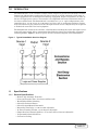
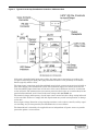
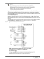
DISCONTINUED
PRODUCT
POWER PROTECTION
SmartSwitch™
Automatic Transfer Switch
Installation and
Operation Manual
DISCONTINUED
PRODUCT
TABLE OF CONTENTS
IMPORTANT SAFETY INSTRUCTIONS . . . . . . . . . . . . . . . . . . . . . . . . . . . . . . . . . . . . . . . . . . . . .1
1.0
INTRODUCTION . . . . . . . . . . . . . . . . . . . . . . . . . . . . . . . . . . . . . . . . . . . . . . . . . . . . . . . 2
1.1
Specifications . . . . . . . . . . . . . . . . . . . . . . . . . . . . . . . . . . . . . . . . . . . . . . . . . . . . . . . . . . . . 2
1.1.1
1.1.2
1.1.3
General Specifications . . . . . . . . . . . . . . . . . . . . . . . . . . . . . . . . . . . . . . . . . . . . . . . . . . . . . . 2
Electrical Specifications. . . . . . . . . . . . . . . . . . . . . . . . . . . . . . . . . . . . . . . . . . . . . . . . . . . . . 3
Environmental Specifications . . . . . . . . . . . . . . . . . . . . . . . . . . . . . . . . . . . . . . . . . . . . . . . . 3
2.0
UNPACKING AND INSTALLATION . . . . . . . . . . . . . . . . . . . . . . . . . . . . . . . . . . . . . . . . . . . 5
2.1
Location Considerations. . . . . . . . . . . . . . . . . . . . . . . . . . . . . . . . . . . . . . . . . . . . . . . . . . . . 5
2.2
Input and Output Power Connections. . . . . . . . . . . . . . . . . . . . . . . . . . . . . . . . . . . . . . . . . 6
2.3
Grounding . . . . . . . . . . . . . . . . . . . . . . . . . . . . . . . . . . . . . . . . . . . . . . . . . . . . . . . . . . . . . . 10
2.4
Control Wiring Connections. . . . . . . . . . . . . . . . . . . . . . . . . . . . . . . . . . . . . . . . . . . . . . . . 10
3.0
OPERATING INSTRUCTIONS . . . . . . . . . . . . . . . . . . . . . . . . . . . . . . . . . . . . . . . . . . . . . 11
3.1
Description of SmartSwitch Operation . . . . . . . . . . . . . . . . . . . . . . . . . . . . . . . . . . . . . . . 11
3.2
Status Indicators . . . . . . . . . . . . . . . . . . . . . . . . . . . . . . . . . . . . . . . . . . . . . . . . . . . . . . . . 11
3.3
RS-232 Communications Port . . . . . . . . . . . . . . . . . . . . . . . . . . . . . . . . . . . . . . . . . . . . . . 12
4.0
OPERATOR CONTROLS . . . . . . . . . . . . . . . . . . . . . . . . . . . . . . . . . . . . . . . . . . . . . . . .14
4.1
Bypass/Transfer Control Switch . . . . . . . . . . . . . . . . . . . . . . . . . . . . . . . . . . . . . . . . . . . . 14
5.0
OPERATING GUIDELINES . . . . . . . . . . . . . . . . . . . . . . . . . . . . . . . . . . . . . . . . . . . . . . . 15
6.0
MAINTENANCE . . . . . . . . . . . . . . . . . . . . . . . . . . . . . . . . . . . . . . . . . . . . . . . . . . . . . . 17
DISCONTINUED
PRODUCT
i
FIGURES
Figure 1
Figure 2
Figure 3
Figure 4
Figure 5
Figure 6
Typical SmartSwitch One-Line Diagram . . . . . . . . . . . . . . . . . . . . . . . . . . . . . . . . . . . . . . . . . . 2
Typical 15 to 20 Amp SmartSwitch Rackmount Unit . . . . . . . . . . . . . . . . . . . . . . . . . . . . . . . . 7
Typical 25 to 60 Amp SmartSwitch Underfloor / Wallmount Unit . . . . . . . . . . . . . . . . . . . . . . 8
Typical Input and Output Power Connections . . . . . . . . . . . . . . . . . . . . . . . . . . . . . . . . . . . . . . 9
Control Wiring Connections . . . . . . . . . . . . . . . . . . . . . . . . . . . . . . . . . . . . . . . . . . . . . . . . . . . 10
Bypass / Transfer Control Switch . . . . . . . . . . . . . . . . . . . . . . . . . . . . . . . . . . . . . . . . . . . . . . . 14
TABLES
Table 1
Table 2
Table 3
Table 4
Table 5
Table 6
Table 7
ii
SmartSwitch™ Ratings . . . . . . . . . . . . . . . . . . . . . . . . . . . . . . . . . . . . . . . . . . . . . . . . . . . . . . . . 4
SmartSwitch Status Indicators . . . . . . . . . . . . . . . . . . . . . . . . . . . . . . . . . . . . . . . . . . . . . . . . . 11
RS-232 ASCII Communication Port Customer Commands . . . . . . . . . . . . . . . . . . . . . . . . . . . 12
Example View Status Response . . . . . . . . . . . . . . . . . . . . . . . . . . . . . . . . . . . . . . . . . . . . . . . . . 12
Example View Event Log Response . . . . . . . . . . . . . . . . . . . . . . . . . . . . . . . . . . . . . . . . . . . . . . 13
Example View Settings Response . . . . . . . . . . . . . . . . . . . . . . . . . . . . . . . . . . . . . . . . . . . . . . . 13
DISCONTINUED
PRODUCT
IMPORTANT SAFETY INSTRUCTIONS
!
WARNING
THERE ARE NO USER-SERVICEABLE PARTS INSIDE THE
REMOVABLE ELECTRONICS MODULE. OPENING OR
REMOVING THE COVER OF THE REMOVABLE ELECTRONICS
MODULE MAY EXPOSE HAZARDOUS VOLTAGES, EVEN WHEN
THE SMARTSWITCH™ IS IN BYPASS. DO NOT ATTEMPT TO
SERVICE THIS PRODUCT YOURSELF. REFER ALL SERVICING
TO QUALIFIED SERVICE PERSONNEL.
NOTE
Read the entire User’s Manual before installing and operating the
SmartSwitch. Adhere to all operating instructions and warnings on the
unit and in this manual.
Liebert Corporation neither recommends nor knowingly sells this product
for use with life support or other FDA-designated “critical” devices.
The SmartSwitch is suitable for indoor use only. Protect unit from
excessive moisture and install in an area free from flammable liquids,
gases, or corrosive substances.
The unit is designed to operate from solidly grounded AC power sources
only. Provide input overcurrent protection in accordance with the unit
ratings. Wire and ground the unit according to national and local
electrical safety codes.
!
!
!
CAUTION
The unit is supplied by two power sources. Unit may be
electrically live if either of the two input sources is ON, even
when the electronics module is removed. To isolate the unit, turn
OFF and lock out BOTH input power sources.
CAUTION
If unit is furnished with input power plugs, the ground (earth)
leakage current must not exceed 2.75 milliamperes. Most
information technology equipment meets this requirement if no
more than 4 pieces of equipment are powered from this unit. Note:
These instructions may be modified by local wiring regulations.
CAUTION
This unit complies with the limits for a Class A digital device,
pursuant to Part 15 Subpart J of the FCC rules. These limits
provide reasonable protection against harmful interference in a
commercial environment. This unit generates, uses and radiates
radio frequency energy and, if not installed and used in
accordance with this instruction manual, may cause harmful
interference to radio communications. Operation of this unit in a
residential area may cause harmful interference which the user
must correct at his own expense.
DISCONTINUED
PRODUCT
1
1.0
INTRODUCTION
The SmartSwitch™ is an automatic transfer switch designed to provide fast automatic transfers
between two independent, synchronous AC power sources to provide continuity of AC power to
critical equipment, such as information technology equipment, despite irregularities in either of
the two AC input power sources. The transfer is accomplished with sense and transfer times of
less than 6 milliseconds. The SmartSwitch is available in a 2, 3, or 4 pole configurations, with
ampacities of 13, 15, 20, 25, 30, 50, or 60 amps, in a floor, wall, or rack mount packages. Inputs
may be hardwired or plug connected to the two input branch circuits. Outputs may be receptacles
or hardwired connected to the load equipment.
The SmartSwitch consists of two modules, a fixed module containing the input and output connections and bypass switch with a compartment that holds the plug-in and removable electronics/
switching module. Figure 1 shows a typical one-line schematic diagram of the SmartSwitch.
Figure 1
Typical SmartSwitch One-Line Diagram
1.1
Specifications
1.1.1
General Specifications
2
•
•
•
•
•
•
•
•
•
•
Manual and Automatic Transfers.
Sense and Transfer Time: Less than 6 milliseconds.
Break-Before-Make Switching.
Selectable Preferred Source.
Selectable Auto/Manual Retransfer.
Retransfer Time Delay: 1 to 60 seconds adjustable.
In-Phase Transfer Window: 1 to 20 degrees adjustable.
Output Overload Transfer Inhibit: 1 to 10 times full load current adjustable.
Programmable Switch Self Test.
Convection Cooling.
Introduction
DISCONTINUED
PRODUCT
1.1.2
Electrical Specifications
1.1.3
Environmental Specifications
• Nominal input voltage
120 or 208 volts single phase 2W+G, 60 Hz
220, 230, or 240 volts single phase 2W+G, 50 Hz
208/120 volts single phase 3W+G, 60 Hz
208 volts three phase, 3W+G, 60 Hz
208/120 volts three phase, 4W+G, 60 Hz
380, 400, or 415 volts three-phase 3W+G, 50 Hz
380/220, 400/230, or 415/240 volts three phase 4W+G, 50 Hz
Solidly grounded power sources
• Branch circuit breaker rating
15, 20, 30, or 60 amps, 60 Hz
13, 25, or 50 amps, 50 Hz
• Maximum continuous current
12, 16, 24, or 48 amps, 60 Hz
13, 25, or 50 amps, 50 Hz
• Load power factor range: 0.5 to 1.0, leading or lagging.
• Load crest factor: up to 3.5.
• Source voltage distortion: up to 10% THD.
• Overload capability: 125% of continuous current for 2 hours, 1000% for 2 cycles minimum.
• Overcurrent Protection: External overcurrent protection provided by the supply branch circuit breakers.
• Short circuit withstand capability: up to 20,000 symmetrical amps, protected by internal fusing.
• Withstands Transient Voltage Surges up to 6 kV as defined by IEEE C62.41 for Category A3.
• Meets FCC Part 15 Class A Emission Limits.
• ETL Listed under UL Standard 1008.
• 50 Hz units are CE marked for compliance with the EMC and Low Voltage Directives.
• Redundant Control Power Supplies.
• Integral Maintenance Bypass.
• Eight Isolated Normally Open, Form A Switch Status Contacts.
• RS-232 Communications Port
• Hot-Swap, Plug-In Electronics Module.
•
•
•
•
•
•
Storage temperature range: -40° to +60°C
Operating temperature range: 0° to 40°C.
Relative Humidity: 0 to 95% without condensation
Operating Altitude: up to 5000 feet (1500 meters) above sea level without derating.
Storage/Transport Altitude: up to 40,000 feet (12,000 meters) above sea level.
Audible Noise: less than 45 dBA at 5 feet (1.5 meters).
Introduction
DISCONTINUED
PRODUCT
3
Table 1
SmartSwitch™ Ratings
No. of Conductors
OPD*
Enclosure
Connector
Designation
Receptacle
Voltage
Phase
Neutral
Gnd
Poles
Amps
Type
Refer to
IBMA
IBMB
IBMC
IBMD
IBME
420R9V
460R9V
515R2
515R4
520R2
520R4
530R1
615R2
620R2
630R1
1420R1
1430R1
1520R1
L515R1
L520R1
L530R1
L615R1
L620R1
L630R1
L1420R1
L1430R1
L1520R1
L1530R1
L2120R1
L2130R1
FW120
FW130
FW220
FW230
FW230N
FW330
FW330N
FW360
FW113
FW325N
FW350
3743
3744
3753
3754
7324
420R9V
460R9V
5262
(2) 5262
5362
(2) 5362
9308
5662
5462
9330
8410
9430
8420
4710
2310
2610
4560
2320
2620
2410
2710
2420
2720
2510
2810
None
None
None
None
None
None
None
None
None
None
None
208
208
208
208
208
208
208
120
120
120
120
120
208
208
208
120/208
120/208
208
120
120
120
208
208
208
120/208
120/208
208
208
120/208
120/208
120
120
208
208
208/120
208
208/120
208
230
400/230
400
2
3
2
3
3
3
3
1
1
1
1
1
2
2
2
2
2
3
1
1
1
2
2
2
2
2
3
3
3
3
1
1
2
2
2
3
3
3
1
3
3
—
—
—
—
—
—
—
1
1
1
1
1
—
—
—
1
1
—
1
1
1
—
—
—
1
1
—
—
1
1
1
1
—
—
1
—
1
—
1
1
—
1
1
1
1
1
1
1
1
1
1
1
1
1
1
1
1
1
1
1
1
1
1
1
1
1
1
1
1
1
1
1
1
1
1
1
1
1
1
1
1
1
2
3
2
3
3
3
3
1
1
1
1
1
2
2
2
2
2
3
1
1
1
2
2
2
2
2
3
3
3
3
1
1
2
2
2
3
3
3
1
3
3
20
15
30
30
60
20
60
15
15
20
20
30
15
20
30
20
30
20
15
20
30
15
20
30
20
30
20
30
20
30
20
30
20
30
30
30
30
60
13
25
50
R
U
U
U
U
U
U
U
R
R
R
U
R
R
U
U
U
U
R
R
U
R
R
U
U
U
U
U
U
U
R
U
R
U
U
U
U
U
R
U
U
Figure 2
Figure 3
Figure 3
Figure 3
Figure 3
Figure 3
Figure 3
Figure 3
Figure 2
Figure 2
Figure 2
Figure 3
Figure 2
Figure 2
Figure 3
Figure 3
Figure 3
Figure 3
Figure 2
Figure 2
Figure 3
Figure 2
Figure 2
Figure 3
Figure 3
Figure 3
Figure 3
Figure 3
Figure 3
Figure 3
Figure 2
Figure 3
Figure 2
Figure 3
Figure 3
Figure 3
Figure 3
Figure 3
Figure 2
Figure 3
Figure 3
Consult Factory for other available connectors not shown.
* OPD - Maximum size of Overcurrent Protection Device (fuse or circuit breaker) supplying SmartSwitch.
4
Introduction
DISCONTINUED
PRODUCT
2.0
UNPACKING AND INSTALLATION
A quality installation begins on the receiving dock.
Upon receipt and before unpacking, inspect the shipping container for damage or mishandling. If
carton is damaged, note on shipper’s receipt and check for concealed damage. If any damage as a
result of shipping is observed, file a damage claim with the shipper within 24 hours and contact
your local Liebert representative or Liebert Customer Service and Support at 1-800-543-2378 to
inform them of the damage claim and the condition of the equipment.
If unit is to be stored before installation, it is recommended to store the unit in a dry environment
with temperatures in the range of 0°C to 40°C. Use original packing materials or other suitable
means to keep the unit clean. When opening the shipping carton, use care not to puncture the carton with sharp objects.
The unit is of a size and weight that it can be easily moved to its intended location. Refer to the
unit dimensions shown in Figure 2 and Figure 3. Typical unit weights are less than 70 pounds
(32 kg) for the wall or underfloor enclosure and less than 40 pounds (18 kg) for the rackmount
enclosure.
2.1
Location Considerations
The unit is designed to be installed indoors where the ambient air temperature is in the range of
0°C and 40°C with a relative humidity of 0% to 95% non-condensing.
The underfloor and wall mount enclosures are designed to withstand moderate amounts of moisture such as is normally available under a computer room raised floor. Do not operate the units in
standing water.
!
CAUTION:
Do not locate or operate the unit in hazardous areas where there
is conductive or explosive dust, flammable liquids or gases, or
corrosive substances.
Altitude - The standard units are designed for full load operation up to 5000 feet (1500 meters)
above sea level. For higher altitude applications, contact your local Liebert Representative or
applications engineering.
Heat Output - The units produce minimal heat output during normal operation. The typical heat
output, which should be included in any calculations for room heat load, is less than 260 BTU/
Hour (80 W/Hour).
Rackmount Installation - The rackmount enclosure is designed to fit into an EIA Standard 19
inch rack. For rackmount installation, support the unit on a shelf, bracket, or slide. Do not secure
only by the front mounting plate. Secure the unit into the rack using four screws through the
front plate. See Figure 2.
Unpacking and
Installation
DISCONTINUED
PRODUCT
5
2.2
Input and Output Power Connections
All wiring should be installed by a qualified electrician. All wiring must comply with NEC and
applicable local codes.
!
!
WARNING
RISK OF ELECTRICAL SHOCK. HAZARDOUS VOLTAGES ARE
PRESENT INSIDE THE SMARTSWITCH. VERIFY THAT THE ALL
INPUT POWER SOURCES ARE DE-ENERGIZED AND LOCKED
OUT BEFORE MAKING CONNECTIONS INSIDE THE UNIT. THE
SMARTSWITCH IS INTENDED TO BE FED FROM TWO
SOURCES. BE SURE ALL SOURCES OF POWER ARE DEENERGIZED AND LOCKED OUT BEFORE MAKING
CONNECTIONS INSIDE THE UNIT.
WARNING
RISK OF UNIT DAMAGE. THE SMARTSWITCH IS INTENDED TO
BE OPERATED FROM SOLIDLY GROUNDED POWER SOURCES.
OPERATION FROM OTHER THAN SOLIDLY GROUNDED
POWER SOURCES MAY CAUSE MISOPERATION OR DAMAGE
TO THE UNIT.
If the unit is not furnished with input power cables, then input power connections are made to
terminal blocks located inside the unit. Refer to the unit outline drawings furnished with the unit
or Figure 2 and Figure 3 for the location of the input power connections. Terminal blocks for
switches rated 13 to 20 amps accept wires sizes of #14 to #10 AWG. Terminal blocks for switches
rated 25 to 60 amps accept wire sizes of #12 to #6 AWG.
6
Wire Size
AWG
Tightening Torque
Lb.-in (N-m)
#14 - #10
20 (2.3)
#8
25 (2.9)
#6
35 (4.0)
Unpacking and Installation
DISCONTINUED
PRODUCT
Figure 2
Typical 15 to 20 Amp SmartSwitch Rackmount Unit
17.25" (438)
18.5"
(469)
0.85" (21.5)
3.5" (88.9)
0.279"x0.406" (7x10)
5.20"
(132)
Unpacking and
Installation
DISCONTINUED
PRODUCT
7
Figure 3
Typical 25 to 60 Amp SmartSwitch Underfloor / Wallmount Unit
If the unit is furnished with input power cables, the input power connections are made to the
receptacles matching the input power plugs furnished located in close proximity to the SmartSwitch (typically within 3 feet).
The input power connections to the SmartSwitch must include overcurrent protection included as
part of the supply power distribution system. The maximum supply overcurrent protection for
each SmartSwitch input should not exceed 125% of the rated continuous current or as indicated
on the unit label. The maximum size overcurrent protection device (fuse or circuit breaker) for the
particular SmartSwitch used is listed in the unit ratings table (see Table 1).
The nominal voltage and frequency of each input source must match the voltage rating indicated
on the unit label. Failure to comply with this requirement may result in misoperation or damage
to the unit.
Severe input voltage distortion or large ringing transients, such as those caused by utility capacitor switching, may be interpreted by the SmartSwitch as a source failure.
The SmartSwitch is intended to be supplied from two independent AC power sources to provide
protection against a source failure.
8
Unpacking and Installation
DISCONTINUED
PRODUCT
NOTE
The two input sources need to be nominally of the same voltage level,
frequency and phase rotation. To ensure virtually uninterrupted transfers
between the two AC sources, the two input sources must be synchronized,
typically within 5 to 15 electrical degrees. For single phase circuits, be sure
to use the same phase from each input power source to maintain
synchronized inputs to the SmartSwitch.
Figure 4 shows the typical input and output power connections to the SmartSwitch. The SmartSwitch can accept up to 3 phase conductors, a neutral conductor and an equipment grounding conductor per input and output to match the specified supply voltage configuration. See the unit
ratings table (Table 1) for the required number of phase and neutral conductors required for the
particular SmartSwitch used.
For example, for a NEMA 520R2 SmartSwitch application, one phase and neutral conductor and
equipment grounding conductor per source are required whereas for a NEMA L1530R1 SmartSwitch application, three phase conductors and an equipment grounding conductor per source are
required.
The output power connections can be to terminal blocks located inside the SmartSwitch (as shown
in Figure 2, Figure 3, and Figure 4) or to receptacle(s) located on the SmartSwitch.
Figure 4
Typical Input and Output Power Connections
Unpacking and
Installation
DISCONTINUED
PRODUCT
9
2.3
Grounding
Proper, NEC-specified equipment grounding is required for safety purposes. An insulated equipment grounding conductor is recommended to be run with each input and output power connection. The equipment grounding conductors should be at least the minimum size conductor per
NEC Table 250-95 based on the supply overcurrent protection device.
If conduit or other wireway is used as the grounding means, adequate electrical continuity must
be maintained at all conduit connections. The use of isolating bushings with a metal conduit can
be a safety hazard and is not recommended.
In accordance with the NEC, only one equipment grounding system may be used in a single building. As such, both input power sources should be referenced to a common building grounding electrode system. The SmartSwitch input equipment grounding conductors should not be the only
grounding interconnection between the two input power sources.
The SmartSwitch switches all input phase and neutral conductors to maintain complete isolation
of the two input power sources. A common neutral-to-ground bond for the two input sources is not
required for proper operation but is recommended to avoid potential common mode disturbances
when source transfers are made.
2.4
Control Wiring Connections
The SmartSwitch includes relay output contacts and RS-232 communications port for remote
indication of switch status. Figure 2 and Figure 3 show the typical locations of the control connectors. Figure 5 shows the typical control connections. Refer to 3.3 - RS-232 Communications
Port for RS-232 communication port description.
To facilitate connection to the relay contacts, the mating connector with short pigtails of wires is
supplied with the SmartSwitch. Relay contact ratings are 1 amp, 125 VAC or 30 VDC maximum.
Contacts close on the indicated switch condition. The relays are located in the removable electronics module. Contacts are not operational with the electronics module removed.
Figure 5
10
Control Wiring Connections
Unpacking and Installation
DISCONTINUED
PRODUCT
3.0
OPERATING INSTRUCTIONS
NOTE
Read the entire operating instructions section before placing the
SmartSwitch into operation.
NOTE
For continued protection against a source failure, periodic testing of the
SmartSwitch is recommended. For manual testing, see the transfer control
instructions.
3.1
Description of SmartSwitch Operation
The SmartSwitch™ is an automatic transfer switch designed to provide fast automatic transfers
between two independent, synchronous AC power sources to provide continuity of AC power to
critical equipment, such as information technology equipment. One of the two AC inputs is designated as the “preferred” source to which the SmartSwitch will connect the load as long as the designated input source is within acceptable voltage limits. If the preferred source falls outside the
acceptable limits, the SmartSwitch is designed to transfer the output load to the other “alternate”
input source, as long as the alternate source is within acceptable voltage limits and is synchronized with the preferred source within the selected phase synchronization window. The SmartSwitch provides fast, break-before-make transfers to prevent interconnection of the two sources,
even under faulted source conditions. The maximum sense and transfer times are within the tolerance of the IEEE Standard 446 susceptibility curve for information technology equipment to
allow uninterrupted load equipment operation. To prevent the transfer of a output overload or
fault condition, the SmartSwitch automatically disables transfers to the alternate source if the
output current exceeds preset limits.
The SmartSwitch™ consists of two modules, a fixed module containing the input and output connections and bypass/transfer control switch, and a plug-in, removable electronics/switching module. The bypass/transfer control switch is located behind a keylocked, hinged access cover to
restrict access to qualified or designated operators. The plug-in module likewise contains keylocked latches to prevent unauthorized removal of the module. The SmartSwitch is designed to
allow replacement of the removable electronics/switching module without having to de-energize
the load equipment. See the bypass, transfer control, and module replacement instructions for
more information.
3.2
Status Indicators
The SmartSwitch contains seven long-life, status indicators located on the removable electronics
module to indicate the unit and source status. See Table 2 for a listing of the status indicators
and their definitions. The status indicators are active as long as the removable module is in place
and at least one of the two input sources is energized.
Table 2
SmartSwitch Status Indicators
Indicator
Description
ON PREFERRED SOURCE
The output load is connected to the preferred source.
ON ALTERNATE SOURCE
The output load is connected to the alternate source.
PREFERRED SOURCE OK
All phases of the preferred source are within voltage limits.
ALTERNATE SOURCE OK
All phases of the alternate source are within voltage limits.
TRANSFER INHIBITED
Automatic transfer is inhibited. Reasons for transfer (or retransfer) inhibit
include both sources are not available, sources are not synchronized, or the
output load has exceeded the preset limit.
SUMMARY ALARM
The SmartSwitch has detected a fault condition. If both sources are available
and synchronized, then the alarm may indicate a SmartSwitch failure.
ON BYPASS
The bypass/transfer switch is in the bypass position.
S1 PREFERRED*
Source 1 is selected as the preferred source.
S2 PREFERRED*
Source 2 is selected as the preferred source.
*These LED indicators are only provided on the rackmount units.
OperatingDISCONTINUED
Instructions
11
PRODUCT
3.3
RS-232 Communications Port
The SmartSwitch contains an RS-232 ASCII communications port for changing user settings and
remote monitoring of unit status and alarm information. The RS-232 port connections are to a
9-pin “D” connector located on the outside of the unit. See Figure 2 and Figure 3 for the location
of the port and Figure 5 for the port connections.
The default parameters of the communications port are RS-232 terminal emulator protocol using
EIA voltage levels, ASCII Characters, Half Duplex Asynchronous Communications, 9600 Baud
rate, 8 Data Bits, 1 Stop Bit, No Parity, No Handshaking, and <CR> Terminator.
The port uses a query-response format. Commands are divided into two groups, inquiries and settings changes. The list of available customer commands is shown in Table 3. Only one command
is serviced at a time. A password is required to change unit settings. The default password is “Liebert.” Inquiries include viewing unit status, viewing event history log, and viewing settings. Typical inquiry responses are shown in Table 4, Table 5, and Table 6.
The Event Log contains the last 175 switch events. The Settings Log contains the last 50 switch
settings changes.
Table 3
RS-232 ASCII Communication Port Customer Commands
Function
View Status
Command
Selections
Y<CR>
View Event Log
B<CR>
View Settings
O<CR>
Set Time*
Thh:mm:ss<CR>
Views up to the last 175 switch events
hh = hours, mm = minutes, ss = seconds
Set Date*
Dmm/dd/yy<CR>
mm = month, dd = day, yy = year
Synchronization Window*
Pn<CR>
n = 1 to 20 degrees
Auto Retransfer Enable*
Rx<CR>
x = 0 for disabled, x = 1 for enabled
Auto Retransfer Delay*
En<CR>
n = 1 to 60 seconds
Load Current Transfer Inhibit*
In<CR>
n = 1 to 10 times full load current
Load Current Inhibit Reset*
Hx<CR>
x = 0 for Manual, x = 1 for Automatic
Auto Transfer Test Enable*
Sx<CR>
x = 0 for disabled, x = 1 for enabled
Auto Transfer Test Settings*
Xmm/dd/yy hh:mm:ss n<CR>
mm/dd/yy = test date, hh:mm:ss = test time,
n = 1 to 365 days between tests
Restore Default Settings*
W<CR>
Clear Event Log*
G<CR>
View Settings Log
C<CR>
Clear Settings Log*
Z<CR>
Views up to the last 50 switch settings
changes
*User Password required for these commands. System prompts for password entry. Password remains valid for 2 minutes
after each password-required command.
Table 4
Example View Status Response
ALARMS
Power Supply Fault
SOURCE and SWITCH
Load on Preferred Source
Switch in Normal Mode
Preferred Source Available
Alternate Source Available
12
Operating Instructions
Alarms include:
Preferred Source Fail, Alternate Source Fail, Out
of Sync, Transfer Inhibit, Peak Overload,
Transfer Test Failed, and Power Supply Fault.
Source and Switch Messages include:
Load on Preferred Source, Load on Alternate
Source, Switch in Normal Mode, Manual Transfer
to S1, Manual Transfer to S2, Bypass to S1,
Bypass to S2, Preferred Source Available, and
Alternate Source Available.
DISCONTINUED
PRODUCT
Table 5
Example View Event Log Response
DATE
TIME
DESCRIPTION
10/21/97
16:34:39
Transferred to Preferred
10/21/97
16:34:39
Transfer Test Passed
10/21/97
16:34:39
Transferred to Alternate
10/21/97
16:34:38
Transfer Test Initiated
10/21/97
16:34:38
Alternate Source Available
09/27/97
07:22:11
In Sync
09/27/97
07:21:08
Out of Sync
06/01/97
02:10:32
Transferred to Preferred
06/01/97
02:10:29
Preferred Source Available
06/01/97
01:29:13
Transferred to Alternate
06/01/97
01:29:13
Preferred Source Fail
Table 6
Logged Events include:
Preferred Source Fail
Preferred Source Available
Alternate Source Fail
Alternate Source Available
Out of Sync
In Sync
Peak Overload
Peak Overload Gone
Transfer Inhibit
OK to Transfer
Power Supply Fault
Power Supply OK
Switch in Normal Mode
Manual Transfer to S1
Manual Transfer to S2
Bypass to S1
Bypass to S2
Transferred to Alternate
Transferred to Preferred
Transfer Test Initiated
Transfer Test Pended
Transfer Test Passed
Transfer Test Failed
Example View Settings Response
CURRENT SETTINGS:
System Time:
10/21/97 16:23:54
Nominal Voltage:
120
Amps:
24
Frequency:
60
Phase:
1
Neutral:
YES
Unit Type:
UNDERFLOOR
Sync Window:
10
Auto Retransfer:
ENABLED
Retransfer Delay:
5
Current Inhibit:
5
Inhibit Type:
MANUAL
Transfer Test:
ENABLED
Next Test:
10/01/97 23:59:58
Test Interval:
90
Preferred Source
S1
OperatingDISCONTINUED
Instructions
13
PRODUCT
4.0
OPERATOR CONTROLS
4.1
Bypass/Transfer Control Switch
The SmartSwitch is furnished with a Bypass/Transfer Control switch. The switch is located
behind the hinged, keylocked cover. Figure 6 shows the switch positions.
Normal Mode. The switch should be left in the “Normal” position for automatic transfer control.
Automatic transfer control is inhibited in all switch positions other than the “Normal” position. In
the “Normal” position, the switch will connect the load to the preferred source as long as the preferred source is available. If the preferred source falls outside of the designated limits while the
switch is in the “Normal” position and the alternate source is available and synchronized, the
SmartSwitch will automatically transfer the load to the alternate source. To disable automatic
transfers, place the Bypass/Transfer Control switch in any position other than “Normal.”
Man. Xfer S1. Placing the Bypass/Transfer Control switch in the “Man. Xfer S1” position commands the SmartSwitch to transfer the load to source 1. If the load is already connected to source
1, automatic transfers to source 2 will be disabled. If the load is connected to source 2, placing the
switch in this position requests the SmartSwitch to transfer the load to source 1. The SmartSwitch will transfer the load to source 1 if source 1 is available and synchronized to source 2. The
SmartSwitch will automatically delay transfer to source 1 until source 1 is available and within
the preset phase synchronization window.
Man. Xfer S2. Placing the Bypass/Transfer Control switch in the “Man. Xfer S2” position commands the SmartSwitch to transfer the load to source 2.
If the load is already connected to source 2, automatic transfers to source 1 will be disabled. If the
load is connected to source 1, placing the switch in this position requests the SmartSwitch to
transfer the load to source 2. The SmartSwitch will transfer the load to source 2 if source 2 is
available and synchronized to source 1. The SmartSwitch will automatically delay transfer to
source 2 until source 2 is available and within the preset phase synchronization window.
Bypass to S1. Placing the Bypass/Transfer Control switch in the “Bypass to S1” position
bypasses the electronics and switching module and connects the load to source 1 by way of the
bypass switch. In this position, control power is still available in the electronics module to allow
the bypass status indicator to remain active. All other indicators, such as source available indicators, are not active in the bypass position. To avoid loss of power to the load, do not rotate
the switch to the “Bypass to S1” position unless the load is connected to source 1 (and
source 1 is available) when the switch is in the “Man. Xfer to S1” position.
Bypass to S2. Placing the Bypass/Transfer Control switch in the “Bypass to S2” position
bypasses the electronics and switching module and connects the load to source 2 by way of the
bypass switch. In this position, control power is still available in the electronics module to allow
the bypass status indicator to remain active. All other indicators, such as source available indicators, are not active in the bypass position. To avoid loss of power to the load, do not rotate
the switch to the “Bypass to S2” position unless the load is connected to source 2 (and
source 2 is available) when the switch is in the “Man. Xfer to S2” position.
Figure 6
14
Bypass / Transfer Control Switch
Operator Controls
DISCONTINUED
PRODUCT
5.0
OPERATING GUIDELINES
After installation, the following operating guidelines can be used for standard equipment operation. These guidelines should be reviewed for any special equipment modifications, special site
conditions, or company policies that may require changes to these operating guidelines.
Initial System Turn-On. After the initial installation, equipment relocation, or extended period
of inoperation, perform the initial system checkout. Have an electrician or other qualified electrical service person verify that the unit has been properly installed and connected to the input
sources, including having the proper supply overcurrent protection and having the required quantity and size of input and output conductors based on the unit rating. Verify that both input power
sources have a nominal voltage and frequency that match the unit rating. Verify that the two
input power sources are synchronized. With load disconnected or turned off, and the Bypass/
Transfer Control switch is in the “Normal” position, apply power to one of the SmartSwitch
inputs. Verify that the SmartSwitch recognizes that the source is available and transfers to that
source. Apply power to the second input and verify that the SmartSwitch recognizes that source is
available, the transfer inhibit indicator is OFF, and transfers to the preferred source. Use the normal operating procedures to verify proper SmartSwitch operation in all modes before connecting
the load equipment. Failure of the SmartSwitch to operate properly may be due to installation
errors, the power sources not being synchronized or otherwise compatible with the SmartSwitch
ratings, or SmartSwitch failure. For assistance contact Liebert Global Services (in the U.S.,
1-800-LIEBERT) or your local Liebert sales representative. After verifying proper SmartSwitch
operation in all modes, connect the load equipment and verify proper load operation in all SmartSwitch operating modes.
After completing the initial system Turn-On, refer to the following operational guidelines for
standard equipment operation.
Normal System Turn-On. The SmartSwitch can be started with either or both input power
sources available and the Bypass/Transfer Control switch in any position. If the Bypass/Transfer
Control switch is not in the “Normal” position, refer to the instructions pertaining to that position
of the switch to return the Bypass/Transfer Control switch to the “Normal” position. If the
Bypass/Transfer Control switch is in the “Normal” position, the SmartSwitch will automatically
transfer the load to whichever source is first available. If both sources are available and synchronized, the SmartSwitch will transfer the load to the designated preferred source. For automatic
source failure protection, the Bypass/Transfer Control switch must be in the “Normal” position.
Manual Transfer to Source 1. Rotating the Bypass/Transfer Control switch to the “Man. XFER
S1” position initiates a manual transfer to source 1. If the load is not currently connected to
source 1, the SmartSwitch will transfer the load to source 1 if source 1 is available and synchronized. If the load is connected to source 1, the SmartSwitch will keep the load connected to source
1, even if source 1 fails. The “Man. XFER S1” position is intended to be used for test transfer purposes and to ensure that the load is connected to source 1 before bypassing to source 1.
Manual Transfer to Source 2. Rotating the Bypass/Transfer Control switch to the “Man. XFER
S2” position initiates a manual transfer to source 2. If the load is not currently connected to
source 2, the SmartSwitch will transfer the load to source 2 if source 2 is available and synchronized. If the load is connected to source 2, the SmartSwitch will keep the load connected to source
2, even if source 2 fails. The “Man. XFER S2” position is intended to be used for test transfer purposes and to ensure that the load is connected to source 2 before bypassing to source 2.
Bypass to Source 1. From the “Normal” position, rotate the Bypass/Transfer Control switch to
the “Man. XFER S1” position to initiate transfer of the load to source 1. Use the indicator lights to
verify that source 1 is available and the load is connected to source 1 before rotating the Bypass/
Transfer Control switch to “Bypass To S1” position. If source 1 is not available and the load is not
connected to source 1 before the switch is rotated to the “Bypass To S1” position, power to the load
may be interrupted. If the load is connected to source 2 and the SmartSwitch will not transfer the
load to source 1, initiate a bypass to source 2.
Bypass to Source 2. From the “Normal” position, rotate the Bypass/Transfer Control switch to
the “Man. XFER S2” position to initiate transfer of the load to source 2. Use the indicator lights to
verify that source 2 is available and the load is connected to source 2 before rotating the Bypass/
Operating
Guidelines
15
DISCONTINUED
PRODUCT
Transfer Control switch to “Bypass To S2” position. If source 2 is not available and the load is not
connected to source 2 before the switch is rotated to the “Bypass To S2” position, power to the load
may be interrupted. If the load is connected to source 1 and the SmartSwitch will not transfer the
load to source 2, initiate a bypass to source 1.
System Shutdown. Power to both SmartSwitch inputs must be turned OFF to ensure system
shutdown.
Transfer Test. For continued protection against the SmartSwitch failure, periodic transfer testing of the SmartSwitch is recommended.
For manual transfer test, with both input sources available and synchronized (no Summary
Alarm present), rotate the Bypass/Transfer Control switch from the “Normal” to “Man. XFER S1”
or “Man. XFER S2” positions (whichever is the alternate source) and observe proper switch transfers (observe change in “On Preferred Source” and “On Alternate Source” indicator lights). Return
Bypass/Transfer Control switch to the “Normal” position and after the retransfer delay, observe
proper switch transfer back to the preferred source (observe change in “On Alternate Source” and
“On Preferred Source” indicator lights).
For automatic (programmable) transfer testing, see the RS-232 communications port information
in 3.3 - RS-232 Communications Port.
Preferred Source Selection. The SmartSwitch allows either input source to be designated as
the preferred source to which the load is transferred to and remains transferred to as long as the
source remains available.
For 13 to 20 amp units in the rackmount enclosure (see Figure 2), to change the preferred source,
place the unit in bypass to either input source, following the bypass procedure. Unlock and the
removable electronics module. Slide out (remove) the electronics module from the main enclosure.
Rotate the Preferred Source selector switch located on the rear of the electronics module to the
desired preferred source. Re-insert the electronics module in the main unit completely and lock
the electronics module.
On 25 to 60 amp units in the wall-mount and underfloor enclosure (see Figure 3), the preferred
source is indicated by labeling on the top of the unit. To change the preferred source, place the
unit in bypass to either input source, following the bypass procedure. Unlock and unlatch the two
latches on the removable electronics module. Remove the electronics module from the main enclosure. Rotate the electronics module and re-insert in the main unit. Re-latch and lock the two
latches on the electronics module. Verify that the labeling on the top of the unit indicates that the
desired source is the preferred source.
16
Operating Guidelines
DISCONTINUED
PRODUCT
6.0
MAINTENANCE
!
!
WARNING
THERE ARE NO USER-SERVICEABLE PARTS INSIDE THE
REMOVABLE ELECTRONICS MODULE. OPENING OR
REMOVING THE COVER OF THE REMOVABLE ELECTRONICS
MODULE MAY EXPOSE HAZARDOUS VOLTAGES, EVEN WHEN
THE SMARTSWITCH IS IN BYPASS. DO NOT ATTEMPT TO
SERVICE THIS PRODUCT YOURSELF. REFER ALL SERVICING
TO QUALIFIED SERVICE PERSONNEL.
CAUTION
The unit is supplied by two power sources. Unit may be
electrically live if either of the two input sources is ON, even
when the electronics module is removed. Lethal voltages exist
inside the unit. Turn OFF and lock out BOTH input power sources
before removing covers or working inside.
Minimal periodic maintenance of the SmartSwitch is required in normal operation. For assurance
of continued protection against SmartSwitch failure, periodic transfer testing of the Smart Switch
is recommended. For manual transfer tests, refer to the transfer test information in the operating
guidelines section of this manual. For automatic transfer tests at programmed intervals, see the
RS-232 communication port information in the operating instructions in 3.3 - RS-232 Communications Port.
The SmartSwitch includes a replaceable electronics module. To replace the electronics module,
follow the unit bypass instructions and place the unit on bypass to the source that is currently
supplying the load. Unlock and unlatch the electronics module. Slide the electronics module out of
the SmartSwitch. Replace the module with a module having the same part number or approved
equivalent. Failure to use the approved replacement module may result in misoperation of or
damage to the SmartSwitch.
Monitoring of the SmartSwitch status (such as by way of the status relay output) is strongly recommended to allow detection of source failures or SmartSwitch failures before loss of power to the
load. A summary alarm in the absence of any source failure or transfer inhibit alarm generally
indicates a SmartSwitch failure. Prompt action to identify and correct the situation is recommended to prevent loss of power to the load.
Even the most reliable equipment can fail. For information or repair assistance, contact your local
Liebert representative or Liebert Global Services. To contact Liebert Global Services in the U.S.,
call 1-800-LIEBERT.
Maintenance
DISCONTINUED 17
PRODUCT
18
Maintenance
DISCONTINUED
PRODUCT
SmartSwitch™
Automatic Transfer Switch
Technical Support
U.S.A.
Outside the U.S.A.
1-800-LIEBERT
+614-841-6755 or 1-800-222-5877
U.K.
+44 (0) 1628 403200
France
+33 (0) 1 43 60 01 77
Germany
Italy
Netherlands
Web site
Worldwide FAX
tech support
+49 89 99 19 220
+39 2 98250 1
+31 (0) 475 503333
http://www.liebert.com
+614-222-5877 option #4
The Company Behind The Products
With more than 500,000 installations around the globe, Liebert is the world leader in computer
protection systems. Since its founding in 1965, Liebert has developed a complete range of support
and protection systems for sensitive electronics:
• Environmental systems: close-control air conditioning from 1.5 to 60 tons.
• Power conditioning and UPS with power ranges from 250 VA to more than 1000 kVA.
• Integrated systems that provide both environmental and power protection in a single, flexible
package.
• Monitoring and control — on-site or remote — from systems of any size or location
Service and support, through more than 100 service centers around the world, and a 24-hour
Customer Response Center.
While every precaution has been taken to ensure accuracy and completeness of this literature,
Liebert Corporation assumes no responsibility, and disclaims all liability for damages resulting
from use of this information or for any errors or omissions.
© 2000 Liebert Corporation. All rights reserved throughout the world. Specifications subject to
change without notice.
Printed in U.S.A.
SL-20320
Revised: February 2001
DISCONTINUED
PRODUCT
® Liebert and the Liebert logo are registered trademarks of Liebert Corporation. All names
referred to are trademarks or registered trademarks of their respective owners.


![[fr] Notice d`installation 2 [it] Manuale d`installazione 27](http://vs1.manualzilla.com/store/data/006115623_1-7e147428fff25a17d59b58fa0bc7bf07-150x150.png)