1
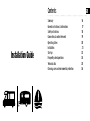
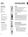
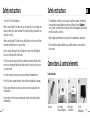
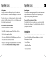
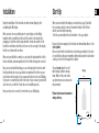
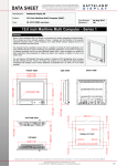
GASLEVEL® mit externem Display Installation Guide Contents Installation Guide Summary General instructions & information Safety instructions Connections & control elements Operating states Installation Start-up Frequently asked questions Technical data Cleaning, care and environmental protection GB 16 17 18 19 20 21 23 24 25 26 Summary General instructions & information Contents of shipment 1 Please note • Make sure the shipment is complete and undamaged. 2 Accessories 1 Level indicator with 3 meter line 2 12 Volt LED display 3 Cover frame 4 User manual & accessories 3 System requirements Incomplete or damaged shipment • Standard propane or butane gas cylinders • The gas cylinders are located in standard containers such as e.g. tow bar lockers or gas cylinder compartments of caravans • Cable routing is as usual through the storage boxes of vehicles 16 The information in this document may change without notice and does not imply obligation of any type on the part of Gaslock GmbH. Please read the user manual before use in any case. The external reserve indicator for gas cylinders may be used only under the following parameters: -20° C < TA < +60° C If you need an additional frame, please order from us using item no. GL-4002-01 grey / GL-4002-02 black / GL-4002-03 white. If an extension of the connecting cable between the level indicator and LED display is required, please use only our special 5-meter extension cable (Due to the cable length can possibly be susceptible to radio frequency fields (power lines, etc.)), item no. GL-4003. • Should the shipment be incomplete or show damage from transport, do not operate the unit. Instead, please contact our customer service department (see page 17). GB Should your goods be damaged, they must be replaced immediately upon discovery. In case of an incomplete or damaged shipment, please consult our customer service department: 4 Gaslock GmbH | Hombrucher Weg 19 | 58638 Iserlohn | Germany Telefon: +49 (0)2371 – 437130-0 | Fax: +49 (0)2371 – 437130-19 Mail: [email protected] | www.gaslock.de | www.gaslevel.de 17 Safety instructions Safety instructions • Use only 12- or 24-volt batteries. • For installations related to areas subject to explosive hazards, all valid national regulations and installation provisions shall be observed. Caution: In case of repair or modification of explosion-protected equipment, the national provisions shall be observed. •When connecting the 12-volt line, take care to supply the correct voltage and make sure that the positive terminal of the battery and the ground cable are attached correctly. •When connecting the 12-volt line, ensure that all lines are disconnected from the mains and that there is no current flow. •Do not open the housing of the level indicator or that of the LED display if these are still connected to the mains. GB • Only original replacement parts may be used for maintenance and repairs. • Do not attach the display within the gas cylinder chamber or in explosionprone areas. • The device may be repaired only by an authorized repair facility. Our customer service department will provide instructions on how to proceed in case of needed repair. Connections & control elements •Use only components and accessories specified by the manufacturer. Level indicator • Protect the device against moisture. Inspect the unit regularly for damage. 1 2 3 4 • Please ensure that any necessary repair is carried out exclusively by the manufacturer. • Please take note to have any needed repair carried out exclusively by the manufacturer. Topview 18 Front with inspection glass Back with connection 12-volt LED display 19 Operating states Operating states Setting mode Operating mode The proper connection of the LED display is through the 12-volt line to the mains. The level indicator is connected to the LED display via the 3-meter line. The setting mode serves to check the function as well as to allow an immediate monitoring of the fill level. In this mode both the 12-volt LED display as well as the level indicator operate in parallel. You can enter the setting mode as follows: • Press the black button of the level indicator • Both the LED of the indicator as well as of the LED display will light up • Place the indicator against the cylinder GB The operating mode is an energy-saving mode. Due to a reduced measurement sequence and the fact that now only the 12-volt LED display lights up, less energy is used and your battery power is conserved. You can enter the operating mode as follows: Press the black button of the level indicator as soon as you have finished with the setting mode, or wait approx. 20 seconds until the indicator switches to the operating mode automatically. Installation • If the cylinder is filled to this level, all LEDs will light up in green; if there is no measurable fill level, they will light up in red. To connect the level indicator with the external display correctly, only the following equipment is needed: • Now place the indicator against the cylinder downstairs in short increments to find the fill level. Please do not pull it down along the cylinder! • Power drill / driver • Drill bit Ø 7 and Ø 12 mm • Accessory kit (included) 20 21 Installation Start-Up Begin the installation of the level indicator with external display by first assembling the LED display. When you have installed the display as described (see page 22) and laid the connecting cable, it is time to determine the limit of the fill level, which is associated with a warning. To do this, you must attach the level indicator to the gas cylinder. When you have chosen a suitable place for your display, use the drilling template, which you will find on the back of the board on the inside of the packaging, to sketch the hole through which the 3-meter line and the 12-volt line will be run. Make sure that these holes are set close enough to the display that the cover frame will cover them. GB When you have drilled the conduits, you can fasten the display with the 4 bolts that are included, and subsequently run the 12-volt line through and connect it. Because it has inner magnets, the level indicator immediately adheres to the steel cylinder. Please ensure that the level indicator is attached perpendicular to the cylinder and that the ultrasonic transmitter (dimly visible under the black rubber coating as a circle) lies flat against the cylinder. Once you have installed the display, you can start laying the 3-meter line with the attached indicator in your gas cylinder compartment. From there you can route the line into the inside of your caravan in the direction of your LED dislay. If you have no conduit at this point to the inside of your caravan, you must drill a hole here also, so that the 5-meter line can be installed properly. The unit is not suitable for refillable tank gas cylinders and gas tanks. Welds or dirty oder rusted gas cylinders may cause inaccurate measurements. Now you only need to connect the 3-meter line to your LED display. Please do not connect consumers during start-up. Bohrschablone Drill jig 46 mm 46 mm 12 mm Ø 7 mm Ø 22 13 mm 23 Frequently asked questions Frequently asked questions If you did not get the results you expected, we hope to address your questions and problems with the following: Why do the red and green LEDs in the level indicator light up alternately when I am trying to determine the fill level? + Make sure that the level indicator lies flat against the cylinder. Why do the LEDs of the level indicator not light up? + Check to make sure the 12-volt LED display is supplied with power. + Check to make sure that the 3-meter line is correctly connected to the LED display. Why can the fill level not be determined correctly with the level indicator ? + Remember that a gas cylinder may only be filled to a capacity of 80 % for safety reasons. + Do not place the level indicator onto rusty areas, the weld, or uneven surfaces. + Do not pull the level indicator downward along the cylinder; rather lift each time before placing it in a new position. + Clean the cylinders with the aid of silicone spray. Why does the green LED not light up on the LED display? + Check to see if the 12-volt LED display is being supplied with power. Technical data External reserve indicator for gas cylinders Item number GL-4001 Dimensions of indicator (LxWxH) 75,4 mm x 30,9 mm x 17,8 mm Dimensions of display (LxWxH) 54,0 mm x 54,0 mm x 9,0 mm Weight indicator 30 g Weight display 10 g Approval mark: 24 GB Cleaning, care and environmental protection F Cleaning the unit Please make sure to keep the rubber surface on the back of the level indicator and the contact surface of the bottle as clean as possible at all times. Avoid harsh detergents if possible as these can damage the unit. Avoid abrasive cleaning pads if possible as these may scratch or damage the unit. Disposal of the unit Do not throw the device into the regular household waste under any circumstances. This product is subject to European Directive 2002/96/EC WEEE (Waste Electrical and Electronic Equipment). Dispose of the unit through an authorized disposal center or at your community waste facility. Observe the currently applicable regulations. If in doubt, contact your waste disposal facility. In case of questions, suggestions or complaints, please contact our customerservice department: Gaslock GmbH Hombrucher Weg 19 | 58638 Iserlohn | Germany Phone: +49 (0)2371 – 437130-0 | Fax +49 (0)2371 – 437130-19 [email protected] | www.gaslock.de | www.gaslevel.de Disclaimer: All information is provided without liability; we assume no responsibility for technical changes, typographical errors and other mistakes. 26 Instructions d‘installation Gaslock GmbH | Hombrucher Weg 19 | 58638 Iserlohn | Germany Telefon: +49 (0)2371 – 437130-0 | Fax: +49 (0)2371 – 437130-19 Mail: [email protected] | www.gaslock.de | www.gaslevel.de