1
D006232_11
RENESAS Ubiquitous Network Layer for Metering Applications
Renesas RUN-M V1.9
User Manual
Rev.3
Revision date:21. November 2006
Renesas Technology Europe GmbH
www.renesas.com
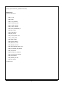
Table of Contents
Table of Contents ....................................................................................................................................................................................... iii
Chapter 1. Preface ....................................................................................................................................................................................... 5
Chapter 2. Abbreviations .............................................................................................................................................................................. 7
Chapter 3. Features...................................................................................................................................................................................... 8
Chapter 4. Hardware Resources .................................................................................................................................................................. 9
4.1. EEPROM requirements..................................................................................................................................................................... 9
Chapter 5. Quick Start ................................................................................................................................................................................ 10
5.1. Required Items................................................................................................................................................................................ 10
5.2. Building the demo project................................................................................................................................................................ 10
5.3. Building the software for a concentrator device ...............................................................................................................................11
5.4. Building the software for a node device ...........................................................................................................................................11
5.5. Enable In-Circuit debugger support .................................................................................................................................................11
Chapter 6. Running the demo application .................................................................................................................................................. 15
6.1. Setting the device serial number..................................................................................................................................................... 15
6.2. Running the concentrator................................................................................................................................................................ 15
6.3. Running a node............................................................................................................................................................................... 17
Chapter 7. Developing own applications .................................................................................................................................................... 18
7.1. Setting the PLC region code ........................................................................................................................................................... 18
Chapter 8. RUN-M™ API Reference .......................................................................................................................................................... 19
8.1. API Function overview..................................................................................................................................................................... 19
8.2. Variable types.................................................................................................................................................................................. 20
8.3. Error codes...................................................................................................................................................................................... 23
Chapter 9. Detailed API description............................................................................................................................................................ 24
RUNInit.............................................................................................................................................................................................. 24
RUNReset ......................................................................................................................................................................................... 26
RUNSend .......................................................................................................................................................................................... 27
fpRunDataConfirm_t........................................................................................................................................................................ 29
fpRunDataIndication_t .................................................................................................................................................................... 30
fpRunJoinIndication_t..................................................................................................................................................................... 31
fpRunLeaveConfirm_t ..................................................................................................................................................................... 32
fpRunLineQualityResponse_t ........................................................................................................................................................ 33
fpRunLeaveIndication_t .................................................................................................................................................................. 34
RUNGet ............................................................................................................................................................................................. 35
RUNSet ............................................................................................................................................................................................. 38
RUNReadChildren............................................................................................................................................................................ 39
RUNReadNeighbours ...................................................................................................................................................................... 40
RUNAddressIsFree .......................................................................................................................................................................... 41
RUNGetLineQuality ......................................................................................................................................................................... 42
iii
RUNEeReadSerial ............................................................................................................................................................................ 43
RUNEeWriteSerial............................................................................................................................................................................ 44
RUNReadDevSerialList ................................................................................................................................................................... 45
RUNResetEeprom............................................................................................................................................................................ 46
RUNEeReadPresetNwId .................................................................................................................................................................. 47
RUNEeWritePresetNwId .................................................................................................................................................................. 48
RUNJoin............................................................................................................................................................................................ 49
RUNLeave......................................................................................................................................................................................... 51
RUNForceLeave ............................................................................................................................................................................... 52
RUNPingParent ................................................................................................................................................................................ 53
RUNRxLed_On ................................................................................................................................................................................. 54
RUNRxLed_Off................................................................................................................................................................................. 55
RUNTxLed_On ................................................................................................................................................................................. 56
RUNTxLed_Off ................................................................................................................................................................................. 57
Chapter 10. Additional Information ............................................................................................................................................................. 58
REVISION HISTORY.................................................................................................................................................................................. 59
Figure 1: The RUN-M™ software architecture ............................................................................................................................................. 6
Figure 2: The RUN-M™ project structure................................................................................................................................................... 10
Figure 3: HEW build configuration...............................................................................................................................................................11
Figure 4: Creation of an E8 debug session ................................................................................................................................................ 12
Figure 5: Setting of the E8 debug session.................................................................................................................................................. 12
Figure 6: Debug download module settings ............................................................................................................................................... 13
Figure 7: E8 emulator settings.................................................................................................................................................................... 13
Figure 8: E8 driver settings......................................................................................................................................................................... 14
iv
Chapter 1. Preface
Cautions
1.
This document may be, wholly or partially, subject to change without notice.
2.
All rights reserved. No one is permitted to reproduce or duplicate, in any form, a part or this entire document without the written
permission of the Renesas Technology Europe GmbH.
Trademarks
All brand or product names used in this manual are trademarks or registered trademarks of their respective companies or
organisations.
IT800 is a trademark owned by Yitran communications
Copyright
© Renesas Technology Europe GmbH 2006. All rights reserved.
Website:
http://www.renesas.com/
Introduction
This document describes the API interface of the Renesas Ubiquitous Network Layer for Metering Applications (abbr. RUN-M™),
focusing the development of a user application software.
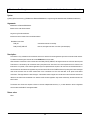
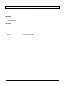
Software structure
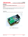
The following diagram outlines the structure of the protocol stack. The RUN-M™ layer utilizes the Renesas/Yitran data link layer
(DLL) based on IT800.
5
M16C/6S
Application Layer (RTOS Task)
Application Programming Interface
RTOS
RUN-M™ layer
Renesas/Yitran Data Link Layer
Physical Layer (PLC)
Figure 1: The RUN-M™ software architecture
The protocol stack runs in a multitasking RTOS environment. The user application is implemented as in a single customizable task.
6
Chapter 2.Abbreviations
Acronym
Description
RUN-M™
Renesas Ubiquitous Network Layer for Metering
API
Application Programmer’s Interface
PHY
Physical Layer
RTOS
Real Time Operating System
PLC
Power Line Communication
DLL
Data Link Layer
DSN
Device Serial Number
7
Chapter 3.Features
Features of the current version of the Renesas RUN-M™ software:
o
Configurable as a Concentrator or Node
o
Built-in In-Circuit debugger support
o
Includes demo application
o
Real time operating system support
o
Up to 1023 networks supported, each including one concentrator and up to 1785 nodes (255 per level)
o
Automatic join on power-up with automatic address assignment
o
Graceful or forced removal of a network participant
o
Automatic optimized network setup by intelligent and configurable join algorithm
o
Data transmission from the node to the concentrator
o
Data transmission from the concentrator to the node
o
Multi-stage routing (repeating) up to seven levels
o
EEPROM based network configuration recovery
o
Mapping of RUN-M™ addresses to the unique serial number of each device within the concentrator
o
Detection and resolution of address conflicts
o
Customizable EEPROM drivers
o
Communication overhead reduction by storing a sub tree table in each node
8
Chapter 4.Hardware Resources
The RUN-M™ network layer and the underlying data link layer are utilizing the following hardware resources of the M16C/6S processor:
Timers:
Timer TA0, TA1, TA2, TA4
Serial I/O:
- UART0 is used for serial communication (e.g. to a PC) and debug output, it can be used by the application layer. Examples
are included in the file usermain.c.
- UART2 is used for I2C communication to a serial EEPROM.
- SI/O4 is internally used for PLC communication.
Note that the stack size of the application task is limited to 280 Bytes.
Please consider this when developing applications based on the RUN-M™ network layer.
4.1.EEPROM requirements
For RUN-M an EEPROM is mandatory. The EEPROM size and access speed can be configured at the initialization of RUN-M. The
following EEPROM types are supported: 16KBit, 32KBit, 64KBit, 128KBit, and 256KBit. The minimum requirement for the EEPROM size
of the concentrator configuration is 128Kbit. The minimum EEPROM size of the node configuration is 16KBit. Please note that the
EEPROM is used to store the network configuration of each node, additionally the concentrator stores the serial number of each network
participant, if no EEPROM with the mentioned sizes is available the RUN-M™ protocol layer will not start when the function RUN_Init() is
called.
When selecting the EEPROM speed, the data sheet of the used EEPROM type should be checked carefully, if the wrong communication
speed is set the EEPROM data maybe corrupted. The following EEPROM speeds are supported by RUN-M: 100KBit/s, 200KBit/s, and
400KBit/s.
9
Chapter 5.Quick Start
This chapter describes how to use the Renesas RUN-M™ software with the application example included on the Renesas EVB04EU
PLC board.
5.1.Required Items
The following items are required in order to set up the development environment:
o
Renesas RUN-M™ software with example application
o
Renesas High-performance Embedded Workshop (HEW) Version 4.01
o
Renesas NC30 C compiler for M16C/60 (M3T-NC30WA Version 5.40)
o
Target hardware Renesas PLC board EVB04EU
o
Renesas E8 for debugging and flash programming
o
Renesas Flash Development Tool kit version 3.07 or later
o
Cable to HyperTerminal for monitoring
o
E8 debugger package for HEW
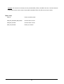
5.2.Building the demo project
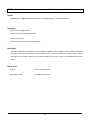
The RUN-M™ software with example application will be delivered in a zip-archive. At first unpack this archive in your working folder. The
project has the following structure:
app
Renesas_RUN_M
Application folder
Concentrator Output folder concentrator
Project folder
Node
Output folder node
src
General sources
inc
Include files
lib
Library files
Figure 2: The RUN-M™ project structure
10
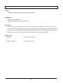
The complete project was created with the HEW 4.01 environment. Start the project by stepping into the workspace folder and open the
*.hws-file. The project can be built as either a concentrator device or as a node device. The HEW environment offers three different build
configurations as shown in the picture below.
Figure 3: HEW build configuration
Select the desired configuration and build the project. The demo application will then be compiled with the appropriate compiler
definitions to act as node or concentrator. The corresponding library (RUN_Node.lib, RUN_Concentrator.lib) will be automatically linked.
5.3.Building the software for a concentrator device
Select “concentrator” as build configuration and build the project. The demo application will then be configured by the global definitions
of this configuration and the corresponding RUN-M™-library will automatically be linked. The output file “RUN_Concentrator.mot“, is
located in the Concentrator folder.
5.4.Building the software for a node device
Select “node” as build configuration and build the project. The demo application will then be configured by the global definitions of this
configuration and the corresponding RUN-M™-library will automatically be linked. The output file “RUN_Node.mot “, is located in the
Node folder.
5.5. Enable In-Circuit debugger support
Note that for E8 support in HEW the debugger package must be installed at first.
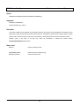
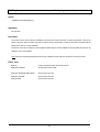
If the HEW debugger package is installed, first connect The E8 to the EVB board and start the HEW. Start HEW and create a new debug
session by selecting the menu Debug/Debug Sessions as shown below.
11
1. Add a new session with the name E8
Figure 4: Creation of an E8 debug session
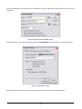
Go to the menu Debug/Debug Settings and set the target and the default debug format to the values shown in the picture below.
1. Set Target and Default Debug format
2. Add Download Modules
Figure 5: Setting of the E8 debug session
12
Next press the Add-Button to set the module to be downloaded to the target in debug mode. Please set the values as shown in the
picture below.
Figure 6: Debug download module settings
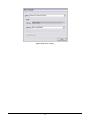
When the E8 session is used in the emulator settings the device type M306S0FAGP has to be selected as shown in the picture below.
Figure 7: E8 emulator settings
After setting the appropriate drivers as shown in the picture below HEW is enabled to debug PLC projects with the E8.
13
Figure 8: E8 driver settings
14
Chapter 6.Running the demo application
To run the demo application at least one EVB04 board is needed acting as a node and another EVB04 board is needed acting as the
concentrator. Connect both devices to a PC using a serial cable and open two HyperTerminal sessions. Please use the following
configuration for the Hyper Terminal: 38400 bps, 8 data bits, no parity, and 1 stop bit.
6.1.Setting the device serial number
When RUN-M™ is used, it is mandatory for the concentrator and the nodes to have a valid device serial number (DSN) stored in the
EEPROM of the EVB04 board. The serial number is an unsigned long value and must be unique for each device, because it is used to
generate a temporary join address on start-up and later for the identification of each node connected to a certain concentrator.
When the EEPROM is empty the serial number has to be set once in the demo application by the user and the device has to be
restarted by a reset. The serial device id can also be changed during the runtime of the node / concentrator by employing the function
RUNEeWriteSerial(). Please note that the protocol stack must be reinitialized afterwards by calling the function RUNInit() to make the
change valid.
The serial number of the node/concentrator is always shown in the header of the demo application menu.
6.2.Running the concentrator
Connect the EVB04 board flashed with the concentrator software to main power. The concentrator is now waiting for connections. A
menu with the following options appears:
1.
Write device serial number to EEPROM
Write a new device serial number to the EEPROM. Enter the number as a 32 bit hexadecimal value.
2.
Print Child table
Show the addresses of all nodes connected to the concentrator (first level).
3.
Send Frame
Send a predefined data packet to the specified node. Enter the address value 0x0000 to perform a broadcast transmission to the
network. Enter the address value 0x0N00 (N valid from 1 to 7) to reach all nodes of a certain level.
4.
Send leave request
Request the specified node to leave the network.
5.
Check address occupation
Requests the specified address is in use or not.
15
6.
Set maximum accepted children for a node
To test any network configuration it is allowed to set the number of accepted children for each node individually (0-255). If the
address 0x0001 is used, the concentrator can be configured. Broadcasts (0x0000) and Levelcasts (0x0N00) are valid address
values too, allowing the force the number of accepted children for a certain level or the complete network.
7.
Switch on LEDS on a node.
If the Renesas EVB04 boards are used the LEDS on the top of the board can be switched on for debugging purpose with this
command. Broadcasts (0x0000) and Levelcasts (0x0n00) are valid address values too.
8.
Switch off LEDS on a node.
If the Renesas EVB04 boards are used the LEDS on the top of the board can be switched off for debugging purpose with this
command. Broadcasts (0x0000) and Levelcasts (0x0n00) are valid address values too.
9.
Get line quality of a node
Get information about the connection quality on the route from the concentrator to the target address.
10. Send force leave
If a leave request fails a node can be removed from the network without confirming the leave request. A force leave removes the
node from the child table of its parent and deletes its entry in the serial id table of the concentrator.
11. Reset EEPROM
The EEPROM reset declares the parameters stored in the EEPROM of the device as invalid. Please perform the command only
before resetting or powering down the device, after reset or power up the EEPROM data will be cleaned, this may take around 2
minutes on the concentrator.
Note: Please perform a reset, when the EEPROM is used the first time!
12. Get next level ID
This option prints out the state of the level below the current device.
If 0 the underlying level is full, if 1 the level has space for at least on note.
13. Set network id
Set the predefined network id. When EEPROM was empty before the value is NO_PRESET_NWID = 0xFFFF. The value can be
set back to this value at any time. NO_PRESET_NWID means that the concentrator will have the default network id (0x142) and for
nodes that they can join at any network. If the network id was changed the device must be reset to make the change valid.
16
6.3.Running a node
After the concentrator has been started, connect an EVB04 board flashed with the node software to main power. The node tries to join
the network. After several seconds (can be 16s or even more) a menu appears when the node successfully joined the network. The
address 0x0101 should now be in the child table of the concentrator. The menu of the node has the following options:
1.
Write device serial number to EEPROM
Write a new device serial number to the EEPROM. Enter the number as a 32 bit hexadecimal value.
2.
Print Child table
Show the addresses of all child nodes connected to the current node (current nodes level + 1)
3.
Send Frame
Send a predefined data packet to the concentrator.
4.
Join
If the node failed to join the network at start-up, this option can be used to try to join again.
5.
Print Parent
Output the address of the parent node.
6.
Get next id value
This option prints out the state of the level below the current device.
If 0 the underlying level is full, if 1 the level has space for at least on note.
7.
Reset EEPROM
The EEPROM reset declares the parameters stored in the EEPROM of the device as invalid. Please perform the command only
before resetting or powering down the device, after reset or power up the EEPROM data will be refreshed, this may take several
seconds for a node.
Note: Please perform a reset, when the EEPROM is used the first time!
8.
Set predefined network ID
Set the predefined network id. When EEPROM was empty before the value is NO_PRESET_NWID = 0xFFFF. The value can be
set back to this value at any time. NO_PRESET_NWID means that the concentrator will have the default network id (0x142) and for
nodes that they can join at any network. If the network id was changed the device must be reset to make the change valid.
9.
Ping parent node
Send a ping request to the parent node. If no answer was received within a certain period of the it indicated that the parent node left
the network or was powered down.
17
Chapter 7. Developing own applications
The project includes a single RTOS task used for the application layer. The entry point of the task is the function Main_WorkerThread
implemented in the file usermain.c. Please add the main loop of your application code to this function.
7.1. Setting the PLC region code
The region code can be set before initializing the network layer by calling the RUNSet function. If no value was set, the CENELEC-A
Band is selected by default. The following region codes are available:
REGION_EEPROM
Take region code from EEPROM (not yet implemented)
REGION_JPN
Region is Japan
REGION_USA
Region is northern America
REGION_CENELEC_A
CENELEC A
REGION_CENELEC_B
CENELEC B
REGION_CENELEC_A_PLUS
CENELEC A+
Please refer to the example code for implementation details.
18
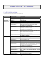
Chapter 8.RUN-M™ API Reference
8.1.API Function overview
The following functions are provided by RUN-M™ to the application layer.
Function name
Initialization functions
Description
RUNInit (…)
Initializing RUN
RUNReset(…)
Reset a node
Communication
RUNSend(…)
Transmit a data packet.
processing function
fpRunDataIndication_t
Call-back function for data reception.
fpRunDataDataConfirm_t
Call-back function informing about the result of a data transmission
fpRunJoinIndication_t
Call-back function indicates a new node has joined the network
(only available for the concentrator device)
fpRunLeaveConfirm_t
Call-back function indicates a node has left the network after the
application layer call the RUNLeave function
(only available for the concentrator device)
fpRunLineQualityResponse_t
Call-back function returns an array of line quality values for each level on
the route from the concentrator to the target node
(only available for the concentrator device)
RUNPingParent(…)
Send a ping request to the parent node
(only available for node devices)
Parameter
RUNGet(…)
Get a value from the RUN-M™ management table
access functions
RUNSet(…)
Set a value in the RUN-M™ management table
RUNReadChildren(…)
Read out the child table of a node
RUNReadNeighbours(…)
Read out the neighbour table of a node
RUNAddressIsFree(…)
Returns if a network address is in use or not.
RUNGetLineQuality(…)
Requests the line quality of the specified target node. Values will be
returned by the call-back function fpRunLineQualityResponse_t.
(only available for the concentrator device)
RUNEeReadSerial(…)
Read the device serial number from EEPROM
RUNEeWriteSerial(...)
Write the device serial number to EEPROM.
RUNReadDevSerialList (…)
Returns a pointer to access the device serial number list of the
concentrator
RUNResetEeprom(…)
Reset the network parameters stored in the EEPROM
RUNEeReadPresetNwId(…)
Read the preset network id from EEPROM
19
RUNEeWritePresetNwId(…)
Write the preset network id to EEPROM
Connection/
RUNJoin(…)
Initiate a node to join the RUN-M™ network
Termination function
RUNLeave(…)
Request a node to leave the RUN-M™ network
(only available for the concentrator device)
RUNForceLeave(…)
Forces a node to leave the RUN-M™ network (without confirmation)
(only available for the concentrator device)
Control functions
RUNRxLed_On(…)
Switch on Rx Led (user defined I/O port)
RUNRxLed_Off(…)
Switch off Rx Led (user defined I/O port)
RUNTxLed_On(…)
Switch on Tx Led (user defined I/O port)
RUNTxLed_Off(…)
Switch off Tx Led (user defined I/O port)
8.2.Variable types
The following special variable types are defined to be used as parameters in the API functions.
The meaning of the variable types will be described in the following chapters.
RUNAddress
typedef unsigned short
RUNAddress;
BYTE
typedef unsigned char
BYTE;
fpRunDataIndication_t
typedef (*fpRunDataIndication_t) RUNAddress uiSourceRUNAddress,
BYTE ucDataLength, BYTE* pucRcvBuffer, RUNStatusCode Status)
fpRunDataDataConfirm_t
typedef (*fpRunDataDataConfirm_t)(void)
(not yet implemented)
fpRunLeaveConfirm_t
typedef (*fpRunLeaveConfirm_t)(RUNAddress uiReleasedRUNAddress, unsigned long lDevSeriamNumber, RUNStatusCode Status);
fpRunJoinIndication_t
typedef (*fpRunJoinIndication_t)(RUNAddress uiNewRUNAddress, RUNAddress uiParentNode,
unsigned long lDevSeriamNumber, RUNStatusCode Status);
fpRunLineQualityResponse_t
typedef (*fpRunLineQualityResponse_t)(BYTE *ucQualityTable);
20
typdef *fpRunLeaveIndication()
typedef (*fpRunLeaveIndication_t)(RUNStatusCode Status);
RUNStatusCode
typedef enum eErrorCodes
{
RUN_OK = 0x00,
RUN_FAILURE,
RUN_DLL_INIT_FAILURE,
RUN_DLL_START_FAILURE,
RUN_DLL_SEND_FAILURE,
RUN_DLL_RECV_FAILURE,
RUN_INVALID_MANAGEMENT_ID,
RUN_EMPTY_TABLE,
RUN_FRAME_ERROR,
RUN_MSG_FAILURE,
RUN_NULLPTR_ERROR = 0x0a,
RUN_NO_FREE_TIMER,
RUN_UNUSED_TIMER,
RUN_INVALIDE_TIMER_ID,
RUN_TIMER_NOT_ACTIVE,
RUN_TIMER_INIT_FAILURE,
RUN_START_MAINTASK_FAILED = 0x10,
RUN_GET_MESSAGE_MEM_FAILED,
RUN_JOIN_FAILURE,
RUN_DEV_SERIAL_ID_CONFLICT,
RUN_LEAVE_REQUEST_PENDING,
RUN_LEAVE_TIMEOUT,
RUN_UNKNOWN_ROUTER,
RUN_PING_TIMEOUT
} RUNStatusCode;
21
RUNManagementItemID
typedef enum eRUNManagementItemID
{
eReceiveDataClass,
eRegion,
eAckModeRetransmission,
eUnackModeRetransmissions,
eSendTimeout,
eSendPriority,
eAckUnackMode,
eSendRate,
eReceiveTimeout,
eParentRUNAddress = 0x20,
eNextID,
eOwnRUNAddress,
eOwnNetworkID,
eOpenAdresses,
eDiscardUnsecured,
eDefaultSecurity,
eMergedLevel,
eMergedLevelNextID,
eMaxAcceptedChildren,
eLineQualityThreshold,
ePingTimeout,
eJoinRetries,
eJoinRetryWait,
eJoinOfferReceptionTime,
eJoinConfirmWait,
eLeaveRequestTimeout,
eEND = 0xFF
} RUNManagementItemID;
DevSerialList
typedef struct tagDevSerialList
{
unsigned long SerialListElement[NUM_LEVELS][MAX_CHILDREN];
}DevSerialList;
22
EEP_Size
typedef enum eEEP_Size
{
EEP_16K = 0x00,
EEP_32K,
EEP_64K,
EEP_128K,
EEP_256K
} RUNEEP_Size;
EEP_Speed
typedef enum eEEP_Speed
{
BPS_100K = 0x00,
BPS_200K,
BPS_400K
} RUNEEP_Speed;
8.3.Error codes
The error codes returned by the RUN-M™- API can be found in chapter 8.2. They are defined in the RUNStatusCode enumeration.
23
Chapter 9.Detailed API description
The following section describes the API functions in detail.
RUNInit
Initializing RUN-M
Syntax:
RUNStatusCode RUNInit (fpRunDataIndication_t fpRunDataIndication, fpRunDataConfirm_t fpRunDataConfirmation,
fpRunJoinIndication_t fpRunJoinIndication, fpRunLeaveConfirm_t fpRunLeaveConfirm,
fpRunLineQualityResponse_t fpRunLineQualityResponse,
fpRunLeaveIndication_t fpRunLeaveIndication,
RUNEEP_Size ucEEPSize, RUNEEP_Speed ucEEPSpeed)
Arguments:
fpRunDataIndication_t fpRunDataIndication
Function pointer to the function called on the reception of new data for the node / concentrator.
fpRunDataConfirm_t fpRunDataConfirmation
Function pointer to the function called to return the result of a data transmission to the application layer.
fpRunJoinIndication_t fpRunJoinIndication
Function pointer to the called when a new node joined at the concentrator.
fpRunLeaveConfirm_t fpRunLeaveConfirm
Function pointer to the function called when a node left the network successfully.
fpRunLineQualityResponse_t fpRunLineQualityResponse
Function pointer to the function returning the result of quality request. Please refer to description RUNGetLineQuality.
fpRunLeaveIndication_t fpRunLeaveIndication
Function pointer to a function called when the network was left by a node (initiated by the concentrator)
RUNEEP_Size ucEEPSize
Parameter to define the size of the EEPROM in kilobit (KBit).
The following values are valid: EEP_16K for 16 KBit, EEP_32K for 32 KBit, EEP_64K for 64 KBit, EEP_128 for 128 KBit, and
EEP_256K for 256 Kbit.
24
RUNEEP_Speed ucEEPSpeed
Parameter to define the communication speed. The communication speed must be check carefully in the data sheet of the used
EEPROM. If the wrong communication speed is used the EEPROM data might be corrupted.
The following values are valid: BPS_100K for 100 KBit/s, BPS_200K for 200 KBit/s and BPS_400K for 400 KBit/s
Description:
The function initializes RUN-M™ including the underlying layer. It has to be called once after power up in the user application task.
It is used in the same way for the concentrator device and for a node device. The call-back function in the arguments has to be
implemented by the user. The types of the function pointers are described in chapter 8.2. If it is desired to change to PLC region
code it has to be done before the RUNInit function is called. By default CENELEC A will be used.
While the initialisation of RUN-M™ the EEPROM parameters will be checked, if they have been declared invalid before by calling
RUNResetEeprom(…) all parameters will be erased, this takes approx 2 minutes for the concentrator.
If the EEPROM parameters of a device are valid (node was connected to a network and RUNResetEeprom was not called before
last power down) the complete network configuration will be restored including the child table. It is not necessary to join the
network again for node devices. For concentrator devices all nodes connected before are restored.
Return value:
RUN_OK
Function successfully ended
RUN_NULLPTR_ERROR
Null pointer was passed to the function
RUN_TIMER_INIT_FAILURE
Failed to initialize the timer module
RUN_DLL_START_FAILURE
Failed to initialize the data link layer
RUN_START_MAINTASK_FAILED
Failed to start to RUN-M™ main task
25
RUNReset
Reset a node / concentrator
Syntax:
RUNStatusCode RUNReset(void)
Arguments:
No arguments.
Description:
The function sets the node / concentrator back to the initial state. In the case that the device is a node, it is no longer connected to
the network. All address values (own address, address of the parent node, network id), the child table and in later releases the
neighbourhood table are deleted. Note that the concentrator will not be notified about the reset operation.
After the reset operation was performed by the application layer, the network can be joined again by calling the RUNJoin function.
When calling RUNReset on the concentrator all information required for the address management are lost. The concentrator stays
operational after e reset, not further actions are required.
Return value:
RUN_OK
Function successfully ended
26
RUNSend
Transmit a data packet
Syntax:
RUNStatusCode RUNSend
(RUNAddress uiTargetRUNAddress, BYTE ucDataLength, BYTE* pucDataBuffer, BYTE ucSecurity, BYTE ucShortCuts)
Arguments:
RUNAddress uiTargetRUNAddress
Address of the target node.
BYTE ucDataLength
Length of the data packed to be transmitted (Max. 100 Bytes).
BYTE* pucDataBuffer
Pointer to the data packet.
BYTE ucSecurity
0x01 enables encryption
0x00 disables encryption
(not yet implemented)
BYTE ucShortCuts
0x01 enables short cutting
0x00 disables short cutting
(not yet implemented)
Description:
The function enables the user application to transmit a data packet with a size from 1 to 100 bytes. Please note that short cutting
and encryption is not included into the current release, thus these parameters are ignored.
The function operates none blocking and will therefore immediately return if no serious error were found in the parameters
passed. The result of each transmission is offered by the call back function of the type fpRunDataDataConfirm_t as an
asynchronous event. Please ensure the user application waits for the confirmation of each data packet before transmitting the
next. The RUN-M™ layer dose not support the confirmation of more than one pending transmission.
27
Return value:
RUN_OK
Function successfully ended
RUN_FRAME_ERROR
Failed to send (e.g. message to long)
RUN_MSG_FAILURE
An internal error occurred
28
fpRunDataConfirm_t
Call-back function for data confirmation
Syntax:
typedef (*fpRunDataConfirm_t)(void)
Arguments:
Not yet implemented.
Description:
The function is called when the result of a pending data transmission is available. Please note that no multiple pending
transmissions can be handled. Please ensure the user application waits for the confirmation of each data packet before
transmitting the next. Note that it is not implemented in the alpha release of the software.
Return value:
None
29
fpRunDataIndication_t
Call-back function for new data indication
Syntax:
typedef (*fpRunDataIndication_t)(RUNAddress uiSourceRUNAddress, BYTE ucDataLength, BYTE* pucRcvBuffer,
RUNStatusCode Status)
Arguments:
RUNAddress uiSourceRUNAddress
Source Address of the received data packet
BYTE ucDataLength
Length of the received data packet
BYTE* pucRcvBuffer
Pointer to the received data
Note: The maximum size of the returned buffer is 100 bytes. For further processing on application layer level please copy the
received data to a special user application buffer.
RUNStatusCode Status
RUN_OK
normal data indication with no errors
RUN_DEV_SERIAL_ID_CONFLICT
only available on the concentrator (see description)
Description:
The function is called when new data for the intention of the node was received. This enables the application layer to handle the
reception of new data as an asynchronous event.
When the Status has the value RUN_DEV_SERIAL_ID_CONFLICT (only concentrator) an address conflict was detected which
can have the following reasons:
1. The device serial number of the incoming data frame is assigned to another node address.
2. The source node address of the incoming data frame has not the same device serial number as stored in the concentrator.
3. The device serial number of the incoming data is unknown.
Return value:
None
30
fpRunJoinIndication_t
Call-back function for join indication
Syntax:
typedef (*fpRunJoinIndication_t)(RUNAddress uiNewRUNAddress, RUNAddress uiParentNode,
unsigned long lDevSerialNumber, RUNStatusCode Status)
Arguments:
RUNAddress uiNewRUNAddress
Address of the new node joined the network.
Note: When the status is RUN_UNKNOWN_ROUTER the variable contains the address of the unknown node.
RUNAddress uiParentNode
Contains the address of the parent node, where the new node has joined.
Note: When the status is RUN_UNKNOWN_ROUTER this variable is set to 0x0000.
unsigned long lDevSerialNumber
Contains the serial number of the node joined the network.
Note: When the status is RUN_UNKNOWN_ROUTER this variable contains the serial id of the unknown node.
RUNStatusCode Status
Returns the status code of the finished join procedure.
RUN_OK
A new node joined successfully.
RUN_UNKNOWN_ROUTER
Please refer to the description.
Description:
The function is only available on the concentrator device. It is called to inform the application layer about a new node joined the
network. The parameter uiNewRUNAddress contains the address of the new node. The parent node address of the new node is
also included, this allows you to get information of the network structure. The Status of the join procedure is returned as RUN_OK
when a new node joined.
If the concentrator receives a join notification frame from an unknown device the status is set to RUN_UNKNOWN_ROUTER.
That means the join notification was forwarded (routed) by a node which can not be found in the serial id table of the concentrator.
Return value:
none
31
fpRunLeaveConfirm_t
Call-back function for leave confirmation
Syntax:
typedef (*fpRunLeaveConfirm_t)(RUNAddress uiReleasedRUNAddress, unsigned long lDevSeriamNumber, RUNStatusCode Status)
Arguments:
RUNAddress uiReleasedRUNAddress
Address of the node left the network.
unsigned long lDevSeriamNumber
Contains the serial number of the node left the network.
RUNStatusCode Status
RUN_OK
node left the network successfully
RUN_LEAVE_TIMEOUT
time out, the target node does not confirm (see description)
Description:
This function is only available on the concentrator device. It is called to inform the application layer that a node has left the network.
To initiate a node leaving the net work the function RUNLeave has to be called.
When the status of the leave confirm contains the value RUN_LEAVE_TIMEOUT, the target node did not confirm the leave request.
That means it is still known by the concentrator and by the parent node. One reason for a leave request time out is a failure in the
transmission of a packet, in this case the application layer can repeat the leave request. If the node does not answer because it is
disconnected from the network the application layer should call the API function RUNForceLeave. By calling this function the target
node will be removed from the serial number table of the concentrator and from the child table of the parent node without
confirmation. The target address is then free again. If the address will be assigned to a new device but the node forced to leave the
network is still active it will be detected as an address conflict and the application layer will be informed by the data indication call
back function.
The timeout value of the leave request is fixed to 5 seconds multiplied with the level (1-7). In later releases it will be configurable
and included to the RUN-M™ management table.
Return value:
None
32
fpRunLineQualityResponse_t
Call-back function returning line quality
Syntax:
typedef (*fpRunLineQualityResponse_t)(RUNAddress uiResponseRUNAddress, BYTE *ucQualityTable);
Arguments:
RUNAddress uiResponseRUNAddress
Address of the node initially returned to quality response. It is the address specified when calling the function RUNGetLineQuality
BYTE *ucQualityTable
Pointer to the first value of the line quality table. The table size is fixed to 7 bytes. Please refer to the description below.
Description:
The function is called after requesting the line quality of a node by calling the function RUNGetLineQuality. It contains the
connection quality for each level-to-level connection on the route from the concentrator to the target node:
Byte 0: Level 0-1 quality
Byte 1: Level 1-2 quality
Byte 2: Level 2-3 quality
Byte 3: Level 3-4 quality
Byte 4: Level 4-5 quality
Byte 5: Level 5-6 quality
Byte 6: Level 6-7 quality
For unused levels the quality value is set to 0x00. Please note that only the lower bits b2-b0 containing the quality value (0-7),
where 7 is the highest quality. Bit b3 s used to indicate data errors and bit b4 is used to indicate double errors, where 1 means
no errors! For further information please refer to the demo application.
Return value:
None
33
fpRunLeaveIndication_t
Call-back indicates a node left the network
Syntax:
typedef (*fpRunLeaveIndication_t)( RUNStatusCode Status)
Arguments:
RUNStatusCode Status
Status of the leave request (at the moment always RUN_OK)
Description:
The call back function informs the application layer, that the node left the network requested by the concentrator.
Return value:
None
34
RUNGet
Get a value from the management table
Syntax:
unsigned short RUNGet (RUNManagementItemID uiParameterID);
Arguments:
RUNManagementItemID uiParameterID
Enumeration value of the desired parameter. (Please refer to the table below)
Description:
The function enables the user application to access the internal management table of RUN.
Please use the enumeration values as shown in the table below.
ID
Type
Value
Receive Data Class:
eReceiveDataClass
Allows to specify an address filter for each node. (E.g. to filter foreign
int
network ids). The filter is set internally depending on the current
communication state.
(Currently for internal use only – do not change).
eRegion
int
Region:
Contains the region code. Please refer to chapter 7.1.
Default: REGION_CENELEC_A
eAckModeRetransmission
uint
Number of retransmissions in acknowledge mode:
Contains the number of retransmissions performed when no
acknowledge for a data transmission was received.
Default: 3
eUnackModeRetransmissions
uint
Number of Retransmissions in unacknowledged mode:
Contains the number of retransmissions when no acknowledge is used.
Default: 0
eSendTimeout
uint
Send Timeout:
(Currently for internal use only – do not change).
eSendPriority
int
Send Priority:
Allows prioritizing a transmission (low / medium / high).
(Currently for internal use only – do not change).
eAckUnackMode
int
Acknowledge/ unacknowledge Mode:
Enables / disables the acknowledging of transmissions, except
broadcasts.
(Currently for internal use only – do not change).
35
eSendRate
ushort
Send Rate:
Contains the transmission speed.
Available send rates:
Fast mode:
JPN/USA: 7.5kbps
Robust mode:
Extra Robust Mde:
JPN/USA:
5kbps
JPN/USA: 1.25kbps
EU: Not supported
EU: 2.5kbps
EU: 0.625kbps
Default: robust mode (SEND_ROBST)
eReceiveTimeout
ushort
Receive Timeout:
(Currently for internal use only – do not change.)
eParentRUNAddress
ushort
Parent RUN-M™ Address:
Address of the parent node in the network.
eNextID
ushort
NextID:
Contains the next free address of the level below the current node, will
be update by the concentrator.
(Currently for internal use only – do not change.)
Own RUN-M™ Address:
eOwnRUNAddress
ushort
RUN-M™ Address when the node has joined the network.
(Do not change.)
Own RUN-M™ network ID:
eOwnNetworkID
ushort
Contains the network id of the current node. – Depends on the value of
the preset network id.
(Do not change.)
eOpenAdresses
ushort
Open Addresses
(Obsolete, will be removed in later versions.)
eDiscardUnsecured
uchar
Discard unsecured responses when encryption
was requested for the response.
(Not supported yet.)
eDefaultSecurity
uchar
Default security setting.
(Not supported yet.)
eMergedLevel
ushort
Level merged with.
(Not supported yet.)
eMergedLevelNextID
uint
Next ID value for level merged with.
(Not supported yet.)
eMaxAcceptedChildren
uchar
Maximum number off accepted children (0-255):
Parameter can be used to build special network configurations.
eLineQualityThreshold
unit
Rx Threshold:
Rx threshold for joining nodes, join offers with a line quality below this
value will be discarded. Note: Change the value after RUNInit() has
been called and before RUNJoin is called. If the value is not changed it
is set to 0x02 (RX_QUALITY_THRESHOLD). The quality index has the
36
range 0-7.
Default: 2
Ping time out:
ePingTimeout
ushort
Timeout value (in ms) for the ping parent function.
Default: 3000 (3s)
eJoinRetries
uchar
Join retries:
Number of retries performed by the function RUNJoin() after failure.
Default: 3
eJoinRetryWait
ushort
Join retry wait:
Time to wait (in ms) when the join procedure will be retried by RUNJoin()
after a failure.
Default: 5000 (5s)
eJoinOfferReceptionTime
ushort
Join offer reception time:
Specifies the time a node waits for incoming join offers. Please note that
the value can be only adjusted in steps of 5ms.
Default: 2000 (2000 * 5ms = 10s)
eJoinConfirmWait
ushort
Join confirm wait:
Specifies the time a node waits for incoming join confirmation sent by
the concentrator. Please note that the value can be only adjusted in
steps of 5ms.
Default: 2000 (3000 * 5ms = 15s)
eLeaveRequestTimeout
ushort
Leave request timeout (valid only for the concnetrator)
Specifies the time the concentrator waits for the reception of a leave
confirm after sending a leave request to a node. The time will be
internally multiplied with the level of the node. Please note that the value
can be only adjusted in steps of 5ms.
Default: 2000 (1000* 5ms = 5s per level)
0xFF
none
Dummy for last Entry.
Return value:
Value of the selected parameter.
When unknown values are requested 0 will be returned.
37
RUNSet
Set a value in the management table
Syntax:
RUNStatusCode RUNSet(RUNManagementItemID uiParameterID, unsigned short* puiParameterValue)
Arguments:
RUNManagementItemID uiParameterID
Enumeration value of the desired parameter. (Please refer to the table at the RUNGet function)
unsigned short* puiParameterValue
Pointer to a variable containing the new value to be set in the management table.
.
Description:
The function allows the application layer to modify value of the management table.
Return value:
RUN_OK
Function successfully ended
RUN_FAILURE
Specified parameter could not be set
RUN_INVALID_MANAGEMENT_ID
An invalid management id was selected
38
RUNReadChildren
Read the child table of a device
Syntax:
RUNStatusCode RUNReadChildren (unsigned short** puiChildTable, unsigned short* puiSize)
Arguments:
unsigned short** puiChildTable
Pointer to the first value of the child table.
unsigned short* puiSize
Pointer to the number of entries in the child table.
.
Description:
The function enables the user application to read the addresses of the child nodes connected to the current node.
Return value:
RUN_OK
Function successfully ended
RUN_EMPTY_TABLE
No child nodes connected to the current node.
39
RUNReadNeighbours
Read the neighbour table of a device
Syntax:
RUNStatusCode RUNReadNeighbours (unsigned short** puiNeighbourTable, unsigned short* puiSize)
Arguments:
unsigned short** puiNeighbourTable
Pointer to the first value of the neighbour table.
unsigned short* puiSize
Pointer to the number of entries in the neighbour table.
.
Description:
The function enables the user application to read the addresses of neighbour nodes. A neighbour node is not directly connected to
the current node but direct communication could be happened due to sufficient signal quality. The neighbour table is used for
short-cutting in later releases of RUN. Please note that the neighbour table and short cutting is not implemented in the current
release.
Return value:
RUN_OK
Function successfully ended
RUN_EMPTY_TABLE
No neighbours are available.
.
40
RUNAddressIsFree
Check address occupation
Syntax:
RUNStatusCode
RUNAddressIsFree (RUNAddress uiRUNAddress, BYTE *pucAddressState);
Arguments:
RUNAddress uiRUNAddress
Address value to be checked (e.g. 0x0101).
BYTE *pucAddressState
Pointer to a byte value returned by the function. If the variable contains 0x01 (TRUE), the requested address is not used in the
network.
Description:
The function enables the application layer the check the usage of an address in the network. When pucAddressState has the value
0x01 (TRUE) the address requested is unused.
Return value:
RUN_OK
Function successfully ended
RUN_FAILURE
Invalid address requested.
41
RUNGetLineQuality
Get the connection quality
Syntax:
RUNStatusCode RUNGetLineQuality (RUNAddress uiRUNAddress);
Arguments:
RUNAddress uiRUNAddress
Target node address (e.g. 0x0101).
Description:
The function enables the user application to get information about the line quality on the route between the concentrator and the
target node. A quality request frame will be send to the target node. The target node answers to the request by sending a quality
response frame. The frame contains a byte array. Each node which is routing the response frame to the concentrator adds the
reception quality of the frame to the byte array. When the concentrator is reached the call-back function
fpRunLineQualityResponse will be called.
Return value:
RUN_OK
Function successfully ended
RUN_FRAME_ERROR
Failed to send (e.g. message to long)
RUN_MSG_FAILURE
An internal error occurred
42
RUNEeReadSerial
Read serial number from EEPROM
Syntax:
RUNStatusCode RUNEeReadSerial (unsigned long *lDevSerialNum);
Arguments:
unsigned long *lDevSerialNum
Pointer to return the device serial number to.
Description:
The function reads and returns the serial number of the device (node or concentrator) from the EEPROM.
Return value:
RUN_OK
Function successfully ended
RUN_FAILURE
Could not access the EEPROM
43
RUNEeWriteSerial
Write serial number to EEPROM
Syntax:
RUNStatusCode RUNEeWriteSerial (unsigned long lDevSerialNum);
Arguments:
unsigned long lDevSerialNum
Serial number to write.
Description:
The function writes the serial number of the device (node or concentrator) to the EEPROM.
Return value:
RUN_OK
Function successfully ended
RUN_FAILURE
Could not access the EEPROM
44
RUNReadDevSerialList
Get access to the device serial list
Syntax:
RUNStatusCode
RUNReadDevSerialList (DevSerialList** pDevSerialList, unsigned short* puiSize);
Arguments:
pDevSerialList
pointer of the user application to the first device serial list of the concentrator.
Please refer to chapter 8.2 for the description of the data type.
puiSize
pointer to return the size of the list (number of elements in the list)
Note:
The size is currently a fixed value of 1785 (Number of levels (7) * max number of nodes on each level (255))
The required memory size can be calculated like: 1785 * 4 byte = 7140 byte
Description:
The function gives the user application access to the device serial list of the concentrator by returning a pointer to a structure which
includes the list, implemented as a two dimensional array. One dimension contains the level of the network tree (1-7) and the other
dimension contains the node id. Please note that the array starts with index 0, for example the serial number of node 0x0201 is
located at position [1][0] in the array. The following code example shows how to access the list:
…..
DevSerialList
*SerialList;
unsigned short unDevSerialListSize;
unsigned long lSerialNumber;
…..
RUNReadDevSerialList(&SerialList,&unDevSerialListSize);
lSerialNumber = SerialList->SerialListElement[0][0]; // get the serial number of node 0x0101
…..
If the serial number of a given device address is zero it is no node with this address present in the network.
The length of the list is a constant value. It is the maximum number of nodes allowed to be connected to the concentrator:
Number of levels (7) * max number of nodes (255) = 1785.
Return value:
RUN_OK
Function successfully ended
RUN_NULLPTR_ERROR
One of the pointers passed was a null pointer
45
RUNResetEeprom
Reset the EEPROM content
Syntax:
RUNStatusCode
RUNResetEeprom ();
Arguments:
none
Description:
The network parameters of the node devices and the concentrator are stored in an EEPROM. The completed network can be
recovered after power down, the join procedure must not be repeated. By calling the function RUNResetEeprom (only before reset
or power down !!) the values are stored in the EEPROM are declared as invalid. After resetting or power up the node/concentrator
the EEPROM data will be erased. For node devices it is required to call RUNJoin() to get connected to the network again. Please
note that the concentrator will lose the complete serial id table too. The serial number of the device is not affected when the
EEPROM data will be erased.
Return value:
RUN_OK
Function successfully ended
RUN_FAILURE
Could not access the EEPROM
46
RUNEeReadPresetNwId
Read preset network id from EEPROM
Syntax:
RUNStatusCode
RUNEeReadPresetNwId (unsigned short *unNetworkId);
Arguments:
unsigned short *unNetworkId
Pointer to return the network id to
Description:
Read the preset network id from EEPROM. If the value NO_PRESET_NWID = 0xFFFF is returned the node can connect to any
network selected by the join decision algorithm. When the value NO_PRESET_NWID is set in the concentrator, the device will
have the network id value of DEFAULT_NETWORK_ID.
Return value:
RUN_OK
Function successfully ended
RUN_FAILURE
Could not access the EEPROM
47
RUNEeWritePresetNwId
Write preset network id to EEPROM
Syntax:
RUNStatusCode
RUNEeWritePresetNwId (unsigned short unNetworkId);
Arguments:
unsigned short unNetworkId
network id to be written
Description:
Write the preset network id to the EEPROM. Nodes can only join at a concentrator with an identical network id, when the preset
network id of a node has the value NO_PRESET_NWID it can join at any concentrator selected by the join decision algorithm. If
the preset network id was changed it is only valid after the device has been restarted. Please note that the network id values 0x3ff
(join network id) and 0x142 (default network id) are reserved and can not be used.
Return value:
RUN_OK
Function successfully ended
RUN_FAILURE
Could not access the EEPROM
48
RUNJoin
Initiate a node to join the network
Syntax:
RUNStatusCode RUNJoin (RUNAddress *pNodeFilter)
Arguments:
RUNAddress *pNodeFilter
Pointer to the first element of the join / node filter list. If the filter is unused the list
have to contain the two values 0x06FF and NODE_FILTER_LIST_END as last value.
Description:
The function RUNJoin initiates the join procedure which connects the node to the network. Once the function was called it is
blocking the calling task (application task) as long as the join procedure is working. After sending a join request to the network the
node is waiting for incoming join offers within the time period defined by the parameter eJoinOfferReceptionTime. During that time
the join algorithm is searching for the best join offer. After the time period has expired a join notification will be send to the
network which must be confirmed by the concentrator. The timeout period for this confirm is defined by the parameter
eJoinConfirmWait in the management table.
If the function returns RUN_OK, the network id, the network address and the network address of the parent node can be read
from the management table with the RUNGet function.
Node / join filter:
The function parameter pNodeFilter defines which nodes are allowed to answer the join request.
The upper byte of the parameter defines which levels are allowed to answer the join request and the lower byte defines the node
ID on each level allowed to answer. The join algorithm tries to join the network with each filter value from the list applied as long
as the node has joined the network. If the filter list ends and the node is still not connected to the network RUN_JOIN_FAILURE
will be returned. By changing the parameter eJoinRetries in the management table the number of join retries performed for each
value in the list can be selected. By default this value is set to 1.
Please refer to the following examples:
Value of pNodeFilter[x]
Meaning
0x0001
Only the concentrator is allowed to answer the join request.
0x01FF
Only the concentrator and all nodes on level 1 are allowed to answer the join request.
0x03FF
Only the concentrator and all nodes on level 1-3 are allowed to answer the join request.
0x030A
Only the concentrator and the nodes with the id 0x01 – 0x0A on the levels 1-3 are allowed to
answer the join request.
0x06FF
The complete network is allowed to answer to join request.
NODE_FILTER_LIST_END
End of list. (Mandatory!)
49
Important: The node filter list must always have the parameter NODE_FILTER_LIST_END as last value. If the filter mechanism
is not used the minimum value in the list must be 0x06FF and NODE_FILTER_LIST_END so that no filter is defined.
Return value:
RUN_OK
Function successfully ended
RUN_GET_MESSAGE_MEM_FAILED
An internal failure occurred.
RUN_MSG_FAILURE
An internal failure occurred.
RUN_JOIN_FAILURE
Failed to join a network.
.
50
RUNLeave
Requesting a node to leave to network
Syntax:
RUNStatusCode RUNLeave (RUNAddress uiTargetRUNAddress)
Arguments:
RUNAddress uiTargetRUNAddress
Target address of the node requested to leave the network.
Description:
The function RUNLeave is only available on the concentrator. It requests a node to leave the network. If a node receives a leave
request it sends a leave notification to the network and performs the RUNReset function. The parent node deletes the address of
the leaving node from the child table. The leave confirmation will additionally be routed to the concentrator to update its address
management.
Note: The RUN-M™ network layer can only handle one leave request at once. When the function is called by the application layer
and a pending leave request is detected the function returns with the status RUN_LEAVE_REQUEST_PENDING, as long as the
pending leave request was not confirmed or a time out happened.
Return value:
RUN_OK
Function successfully ended
RUN_LEAVE_REQUEST_PENDING
Pending leave request detected (see description)
RUN_MSG_FAILURE
An internal failure occurred.
RUN_FRAME_ERROR
An internal failure occurred.
51
RUNForceLeave
Force a node to leave to network
Syntax:
RUNStatusCode RUNForceLeave (RUNAddress uiTargetRUNAddress)
Arguments:
RUNAddress uiTargetRUNAddress
Target address of the node forced to leave the network.
Description:
If a leave request to a node failed, it can be forced to leave the network without confirmation. This function can be used e.g. to
remove nodes from the network which are no longer reachable (powered down). A force leave removes the target address from the
concentrator and from the child table of the parent without requesting the target node. If the target node should be active after a
force leave was performed, it is no longer able to communicate because it is no longer known by the network.
Return value:
RUN_OK
Function successfully ended.
RUN_MSG_FAILURE
An internal failure occurred.
.
52
RUNPingParent
Send ping request to parent node
Syntax:
RUNStatusCode RUNPingParent ()
Arguments:
No arguments.
Description:
This function can be used to check the availability of the parent node. When the function is called a ping request is send to the
parent of the node. When the parent node does not reply to the ping request within a certain timeout period it indicates that the
parent node is down or no longer reachable.
The timeout value can be configured in the management table using the function RUNSet with the parameter ePingTimeout. By
default the value is set to 3000ms.
Note: The function is blocking the application task as long as either the parent nodes has responded or a timeout occurred.
Return value:
RUN_OK
Function successfully ended, parent node is online
RUN_PING_TIMEOUT
Timeout, parent node is offline
RUN_GET_MESSAGE_MEM_FAILED
An internal error occurred
RUN_MSG_FAILURE
An internal error occurred
RUN_FAILURE
An internal error occurred
.
53
RUNRxLed_On
Switch on user defined Rx LED
Syntax:
void RUNRxLed_On ()
Arguments:
No arguments.
Description:
The function allows switching on a LED when new data is received. The function is placed in the file usermain.c. If it is unused
please leave it empty, do not remove it. Do not place more code than required for the I/O port operation in the function.
Return value:
None
.
54
RUNRxLed_Off
Switch off user defined Rx LED
Syntax:
void RUNRxLed_Off ()
Arguments:
No arguments
Description:
The function allows switching off a LED when the reception of new data is finished. The function is placed in the file usermain.c. If it
is unused please leave it empty, do not remove it. Do not place more code than required for the I/O port operation in the function.
Return value:
None
55
RUNTxLed_On
Switch on user defined Tx LED
Syntax:
voild RUNTxLed_On ()
Arguments:
No arguments.
Description:
The function allows switching on a LED when the transmission of data starts. The function is placed in the file usermain.c. If it is
unused please leave it empty, do not remove it. Do not place more code than required for the I/O port operation in the function.
Return value:
None
56
RUNTxLed_Off
Switch off user defined Tx LED
Syntax:
void RUNTxLed_Off ()
Arguments:
No arguments.
Description:
The function allows switching off a LED when the transmission of data ends. The function is placed in the file usermain.c. If it is
unused please leave it empty, do not remove it. Do not place more code than required for the I/O port operation in the function.
Return value:
None
57
Chapter 10.Additional Information
For information about the M16C series microcontrollers refer to the M16C Series Hardware Manual
Further information available for this product can be found on the Renesas web site at:
http://www.renesas.com/
General information on Renesas Microcontrollers can be found at the following URLs.
Global:
http://www.renesas.com/
58
REVISION HISTORY
Rev.
Description
Date
Page
Summary
2
14.03.2006
all
Official document release
3
07.09.2006
all
Updated API function description. Updated tool chain description.
3
21.11.2006
all
Added description for E8 debugger usage
Renesas RUN-M™ V1.9
User Manual
21 November 2006
Publication Date
3
Published by:
Renesas Technology Europe GmbH
©2006 Renesas Technology Europe GmbH , All Rights Reserved
Renesas RUN-M V1.9
User Manual
Renesas Technology Europe GmbH