1
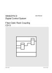
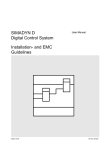
SIMADYN D
Digital Control System
User Manual
Program Memory Sub-Module
MS45
Edition 05.95
DK No. 252346
User Manual, Program Memory Sub-Module MS45
Edition
Status
1
Program Memory Sub-Module MS45
10.90
2
Program Memory Sub-Module MS45
05.95
Copying of this document and giving it to others and the use or
communication of the contents thereof is forbidden without express
authority. Offenders are liable to the payment of damages. All rights
are reserved in the event of the grant of a patent or the registration of
a utility model or design.
We have checked the contents of this Manual to ensure that they
coincide with the described hardware and software. However,
deviations cannot be completely ruled-out, so we cannot guarantee
complete conformance. However, the information in this document is
regularly checked and the necessary corrections included in
subsequent editions. We are thankful for any recommendations or
suggestions.
Contents
Contents
Warning information................................ ................................ ................................ ...................... 1
1. Ordering information ................................ ................................ ................................ ................. 3
2. Function description................................ ................................ ................................ .................. 3
3. Board design................................ ................................ ................................ ............................. 3
4. Application information................................ ................................ ................................ .............. 4
5. Connector assignments................................ ................................ ................................ ............. 4
6. Technical data................................ ................................ ................................ ........................... 5
7. STRUC L mask in the master program................................ ................................ ...................... 5
8. ESD instructions................................ ................................ ................................ ........................ 6
Siemens AG Dk No. 252346
SIMADYN D Hardware User Manual
Edition 05.95
Warning information
Edition 05.95
Siemens AG Dk No. 252346
SIMADYN D Hardware User Manual
Contents
NOTE!
The information in this Manual does not purport to cover all details or variations in equipment, nor to provide
for every possible contingency to be met in connection with installation, operation or maintenance.
Should further information be desired or should particular problems arise which are not covered sufficiently for
the purchaser’s purposes, please contact your local Siemens office.
Further, the contents of this Manual shall not become a part of or modify any prior or existing agreement,
committment or relationship. The sales contract contains the entire obligation of Siemens. The warranty
contained in the contract between the parties is the sole warranty of Siemens. Any statements contained
herein do not create new warranties nor modify the existing warranty.
Warning information
WARNING!
Electrical equipment has components which are at dangerous voltage levels.
If these instructions are not strictly adhered to, this can result in severe bodily
injury and material damage.
Only appropriately qualified personnel may work on this equipment or in its
vicinity.
This personnel must be completely knowledgeable about all the warnings and
service measures according to this User Manual.
The successful and safe operation of this equipment is dependent on proper
handling, installation, operation and maintenance.
Siemens AG Dk No. 252346
SIMADYN D Hardware User Manual
Edition 05.95
1
Warning information
Definitions
*
QUALIFIED PERSONNEL
*
DANGER
*
WARNING
*
CAUTION
*
NOTE
For the purpose of this User Manual and product labels, a „Qualified person“ is someone who is familiar with the
installation, mounting, start-up and operation of the equipment and the hazards involved. He or she must have
the following qualifications:
1. Trained and authorized to energize, de-energize, clear, ground and tag circuits and equipment in accordance
with established safety procedures.
2. Trained in the proper care and use of protective equipment in accordance with established safety
procedures.
3. Trained in rendering first aid.
For the purpose of this User Manual and product labels, „Danger“ indicates death, severe personal injury and/or
substantial property damage will result if proper precautions are not taken.
For the purpose of this User Manual and product labels, „Warning“ indicates death, severe personal injury or
property damage can result if proper precautions are not taken.
For the purpose of this User Manual and product labels, „Caution“ indicates that minor personal injury or
material damage can result if proper precautions are not taken.
For the purpose of this User Manual, „Note“ indicates information about the product or the respective part of the
User Manual which is essential to highlight.
CAUTION!
This board contains components which can be destroyed by electrostatic
discharge. Prior to touching any electronics board, your body must be electrically
discharged. This can be simply done by touching a conductive, grounded object
immediately beforehand (e.g. bare metal cabinet components, socket protective
conductor contact).
WARNING!
Hazardous voltages are present in this electrical equipment during operation.
Non-observance of the safety instructions can result in severe personal injury or
property damage.
It is especially important that the warning information in all of the relevant
Operating Instructions are strictly observed.
2
Edition 05.95
Siemens AG Dk No. 252346
SIMADYN D Hardware User Manual
Contents
1. Ordering information
6DD 1610 - 0AG5
MS45 memory module
for software versions from 3.0 onwards
The MS45 memory module can be used in all SIMADYN D processor modules. When writing into or
reading from the RAM, no wait cycles are required.
A SIMADYN D programming adapter is always required to program the modules.
Programming adapter UP1
Programming adapter UP2
Order No.
Order No.
6DD 1672-0AB0
6DD 1672-0AC0
2. Function description
The MS45 memory module is especially suitable for the start-up phase, as the time-intensive module
erasing is eliminated. Thus, program changes are fast and simple.
The MS45 sub-module is inserted into the processor module through an opening in the front panel
(X50).
A lithium battery is provided on the board to buffer the RAM thus preventing data loss. This, in
conjunction with a data save circuit, ensures that data is reliably backed-up in the RAM when the
power supply voltage dips (below 4.75 V), or the board is withdrawn.
3. Board design
- Small PC circuit board with a 48-pin plug connector
- Memory capacity in Kbyte
Total
RAM
EEPROM
520
512
8
- Starting address, hex
EPROM
80000
EEPROM
7C000
- access time when reading
EEPROM
300 ns
RAM
typ. 85ns (70ns RAM)
max. 88.5 ns
- Access time when writing
EEPROM
RAM
- Data format
EEPROM
RAM
Siemens AG Dk No. 252346
SIMADYN D Hardware User Manual
10 ms
typ. 85ns (70ns RAM)
max. 88.5 ns
8 bit
16 bit
Edition 05.95
3
Application information
- Data back-up in the RAM
min. 2375h
= approx. 3.2 months
typ. 118750h = approx. 162 months
with a full lithium battery
- Data back-up in the EEPROM
min. 100 years
4. Application information
The MS45 sub-module has components which could be destroyed by electrostatic discharge. When
handling the MS45, the following protective measures must be observed:
- Only touch the board, if a grounded object is simultaneously touched (e.g. cabinet ground,
grounding panel)
- Only transport the board in the original conductive packing
- Only set the board down on conductive surfaces
- It must not come into contact with highly insulating materials (e.g. plastics, articles of clothing
manufactured from man-made fibers)
The battery should be replaced after 3 months to protect against data loss.
5. Connector assignments
The three-row, 48-pin connector has the following assignment:
Pin No.
1
2
3
4
5
6
7
8
9
10
11
12
13
14
15
16
Row a
VCC
A2
A5
A8
A11
*OE1
D9
D12
D15
D2
D5
A15
A16
K3
*OE2
*CS5
VCC
GND
Axx
Dxx
*CSx
=
=
=
=
=
*OEx
*WR
=
=
4
Row b
GND
A1
A4
A7
A10
A14
D8
D11
D14
D1
D4
D7
*CS3
*CS4
-GND
Row c
A12
A0
A3
A6
A9
A13
*WR
D10
D13
D0
D3
D6
*CS1
*CS2
BBATT
--
5V power supply voltage
Ground
Address lines 0 to 16
Data lines, 0 to 15
Chip select 1 to 4 - RAMs
Chip select 5 - EEPROM
Output enable 1 and 2
Write enable
Edition 05.95
Siemens AG Dk No. 252346
SIMADYN D Hardware User Manual
Contents
BBATT =
Battery voltage
6. Technical data
Insulation group
Ambient temperature
Storage temperature
Humidity rating
A acc. to VDE 0110 Par.13, Group 2 at 5V DC
0 to 55 degrees C
-40 to +70 degrees C
F acc.to DIN 40040
Dimensions
101.4 * 53.3 mm
Weight in kg
Current drain P5 in mA
0.08
350 typ. (at 16MHz), 490 max.
7. STRUC L mask in the master program
: MS45
"RAM module 512k/8k EEPROM"
Siemens AG Dk No. 252346
SIMADYN D Hardware User Manual
Edition 05.95
5
ESD instructions
8. ESD instructions
Components which can be destroyed by electrostatic discharge (ESD)
Generally, electronic boards should only be touched when absolutely necessary.
The human body must be electrically discharged before touching an electronics board. This can be
simply done by touching a conductive, grounded object directly beforehand (e.g. bare metal cubicle
components, socket outlet protective conductor contact).
Boards must not come into contact with highly-insulating materials - e.g. plastic foils, insulated
desktops, articles of clothing manufactured from man-made fibers.
Boards must only be placed on conductive surfaces.
When soldering, the soldering iron tip must be grounded.
Boards and components should only be stored and transported in conductive packaging (e.g.
metalized plastic boxes, metal containers).
If the packing material is not conductive, the boards must be wrapped with a conductive packing
material, e.g. conductive foam rubber or household aluminum foil.
The necessary ESD protective measures are clearly shown in the following diagram.
a = Conductive floor surface
b = ESD table
c = ESD shoes
Seated
6
d = ESD overall
e = ESD chain
f = Cabinet ground connection
Standing
Edition 05.95
Standing/sitting
Siemens AG Dk No. 252346
SIMADYN D Hardware User Manual
Contents
Siemens AG Dk No. 252346
SIMADYN D Hardware User Manual
Edition 05.95
7
ESD instructions
Drives and Standard Products
Motors and Drive Systems Group
Postfach 3269, D-91050 Erlangen
8
System-Based
Drive Technology
Edition 05.95
Siemens AG Dk No. 252346
SIMADYN D Hardware User Manual