1
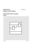
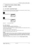
SIMADYN D
Digital Control System
User Manual
SS52 Interface Module
Edition 04.97
DK-No. 247463
User Manual, SS52 Interface Module
Edition
Status
1
SS52 Interface Module
02.96
2
SS52 Interface Module
04.97
Copying of this document and giving it to others and the use or
communication of the contents thereof is forbidden without express
authority. Offenders are liable to the payment of damages. All rights
are reserved in the event of the grant of a patent or the registration of
a utility model or design.
We have checked the contents of this Manual to ensure that they
coincide with the described hardware and software. However,
deviations cannot be completely ruled-out, so we cannot guarantee
complete conformance. However, the information in this document is
regularly checked and the necessary corrections included in
subsequent editions. We are thankful for any recommendations or
suggestions.
Contents
Contents
1. Warning information................................................................................................................................. 1
2. Ordering data........................................................................................................................................... 3
3. Description............................................................................................................................................... 3
4. Board design............................................................................................................................................ 4
5. Serial interfaces ....................................................................................................................................... 4
5.1. SINEC L2 DP............................................................................................................................ 4
5.2. Monitor interface....................................................................................................................... 4
6. Application information............................................................................................................................. 5
7. Shielding.................................................................................................................................................. 5
8. Additional components............................................................................................................................. 5
9. Technical data ......................................................................................................................................... 6
10. Connector assignment of the interfaces.................................................................................................. 6
10.1. Serial interface X5 .................................................................................................................. 6
10.2. Parallel interface CS7 - SS4/SS5............................................................................................ 7
11. STRUC L mask of the SS52 board in the master program...................................................................... 7
12. Others.................................................................................................................................................... 7
12.1. Literature ................................................................................................................................ 7
12.2. Attachments............................................................................................................................ 7
12.2.1. Layout diagram......................................................................................................... 7
12.2.2. Dimension drawing ................................................................................................... 8
12.2.3. Block diagram........................................................................................................... 8
13. ESD instructions..................................................................................................................................... 9
Siemens AG Dk-No. 247463
SIMADYN D Hardware User Manual
Edition 04.97
1. Warning information
Edition 04.97
Siemens AG Dk-No. 247463
SIMADYN D Hardware User Manual
1. Warning information
NOTE!
The information in this Manual does not purport to cover all details or variations in equipment, nor to
provide for every possible contingency to be met in connection with installation, operation or
maintenance.
Should further information be desired or should particular problems arise which are not covered
sufficiently for the purchaser’s purposes, please contact your local Siemens office.
Further, the contents of this Manual shall neither become a part of nor modify any prior or existing
agreement, committment or relationship. The sales contract contains the entire obligation of Siemens.
The warranty contained in the contract between the parties is the sole warranty of Siemens. Any
statements contained herein do not create new warranties nor modify the existing warranty.
1. Warning information
WARNING!
Electrical equipment has components which are at dangerous voltage levels.
If these instructions are not strictly adhered to, this can result in severe bodily
injury and material damage.
Only appropriately qualified personnel may work on this equipment or in its
vicinity.
This personnel must be completely knowledgeable about all the warnings and
service measures according to this User Manual.
The successful and safe operation of this equipment is dependent on proper
handling, installation, operation and maintenance.
Siemens AG Dk-No. 247463
SIMADYN D Hardware User Manual
Edition 04.97
1
1. Warning information
Definitions
*
QUALIFIED PERSONNEL
*
DANGER
*
WARNING
*
CAUTION
*
NOTE
For the purpose of this User Manual and product labels, a „Qualified person“ is someone who is familiar with the
installation, mounting, start-up and operation of the equipment and the hazards involved. He or she must have the
following qualifications:
1. Trained and authorized to energize, de-energize, clear, ground and tag circuits and equipment in accordance with
established safety procedures.
2. Trained in the proper care and use of protective equipment in accordance with established safety procedures.
3. Trained in rendering first aid.
For the purpose of this User Manual and product labels, „Danger“ indicates death, severe personal injury and/or
substantial property damage will result if proper precautions are not taken.
For the purpose of this User Manual and product labels, „Warning“ indicates death, severe personal injury or property
damage can result if proper precautions are not taken.
For the purpose of this User Manual and product labels, „Caution“ indicates that minor personal injury or material damage
can result if proper precautions are not taken.
For the purpose of this User Manual, „Note“ indicates information about the product or the respective part of the User
Manual which is essential to highlight.
CAUTION!
This board contains components which can be destroyed by electrostatic
discharge. Prior to touching any electronics board, your body must be electrically
discharged. This can be simply done by touching a conductive, grounded object
immediately beforehand (e.g. bare metal cabinet components, socket protective
conductor contact).
WARNING!
Hazardous voltages are present in this electrical equipment during operation.
Non-observance of the safety instructions can result in severe personal injury or
property damage.
It is especially important that the warning information in all of the relevant
Operating Instructions are strictly observed.
2
Edition 04.97
Siemens AG Dk-No. 247463
SIMADYN D Hardware User Manual
2. Ordering data
2. Ordering data
SS52: 6DD1688-0AE2
SS52 interface board
3. Description
The SS52 board is an interface board for the SINEC L2 DP PROFIBUS protocol. It is inserted into one of the
three slots of the CS7 subrack, corresponding to the actual configuration. A maximum of three modules can be
inserted in each support board.
The interface module has a serial RS485 interface conforming to the PROFIBUS Standard. This interface is
floating (electrically isolated). The interface is physically located at the 9-pin sub-D socket connector X5.
The connection to the support board is established via the CS7-SS4/SS5 /1/parallel interface at the 48-pin plug
connector X1. In addition to the data-, address- and control bus, this connection is also used to connect the, +5
V, +15 V and -15V module power supply. Data transfer with the processor boards is realized via a 16-kbyte
dual port RAM, which is located on the support board.
A double test socket and a double LED, assigned to each slot, are provided on the support board.
The LEDs have the following function:
LEDs:
H10 / H20 / H30
bright/dark/
flashing
H11 / H21 / H31
(Significance of the function, refer to: „PROFIBUS DP“) Instruction Manual
In addition to the reset function by the power supply, a local reset can be initiated by short-circuiting
(jumpering) the two test sockets at the processor of the appropriate interface module This function has no
effect on the remaining subrack. It is required for the software test and fault finding. During normal operation it
is not permissible to initiate a reset using these sockets.
Siemens AG Dk-No. 247463
SIMADYN D Hardware User Manual
Edition 04.97
3
4. Board design
PROFIBUS interface operation is indicated by an LED on the interface module. It is used for fault finding and
commissioning, and is not externally visible in normal operation when the module is inserted. It has the
following function:
LED:
H1
Function:
bright:
PROFIBUS interface operation
dark:
PROFIBUS interface not operational
There is an 80-pin test connector X20 on the board for hardware diagnostics using a logic analyzer.
Correct hardware functioning is monitored using a "watchdog ".
4. Board design
The board has the following hardware components.
•
•
•
•
•
•
•
•
•
80C186 processor ( 20 MHz )
EPROM ( 256 kbyte ) with firmware
Local processor RAM ( 256 kbyte )
Parallel interface to the support board
RS485 serial interface
Watchdog for NMI monitoring
LED for the operating display of the PROFIBUS interface
Diagnostics connector for the logic analyzer
Diagnostics functionality using the hexadecimal monitor
5. Serial interfaces
5.1. SINEC L2 DP
The connection is either realized via the SINEC L2 bus terminal or the SINEC L2 bus connector at the 9-pin
Sub D socket connector X5. When using the RS485 bus terminal, the cable capacitance must be taken into
account, dependent on the baud rate. Both the bus terminal as well as the bus connector have a terminating
resistor which can be switched-in.
Please refer to the „SINEC Industrial Communications Catalog IK10 1996“ for information regarding SINEC L2
DP as well as the components required to configure a bus system.
5.2. Monitor interface
A hexadecimal monitor runs in parallel on the SS52 in the background. Parameter data of the PROFIBUS are
loaded using the hexadecimal monitor. When a fault/error condition develops, diagnostics is possible via the
hexadecimal monitor so that they can be quickly localized and removed. For space reasons, this interface is
located at the same connector as for the PROFIBUS interface.
The monitor interface is an RS232 interface and cannot be modified.
4
Edition 04.97
Siemens AG Dk-No. 247463
SIMADYN D Hardware User Manual
6. Application information
6. Application information
The interface module can be configured in any slot of the CS7 subrack. A maximum of three interface modules
can be configured for each CS7. No specific sequence has to be followed.
The board must be screwed to the guide rails for perfect functioning, even during start-up.
If the board is inserted in an adapter, the front panel must be connected to the rack housing through a short
cable.
The board may neither be inserted nor withdrawn under voltage.
7. Shielding
The bus cable shield must be grounded, through the largest possible surface area, where the cable enters the
cabinet. The cable shield must be connected to the grounding rail where the cable enters the cabinet. Further,
the shield in the connector housing must be connected to the housing. The connector must be screwed to the
module.
The SIMADYN D EMC Directives and Installation Guidelines /2/ are valid.
8. Additional components
Designation:
CS7 subrack
MLFB:
6DD1662-0AB0
Following data and additional bus components (e.g. fiber-optic
cables) refer to Catalogs IK10 and ST76 (1996)
SINEC L2 bus cable (e.g.:)
6XV1830-0AH10
SINEC L2 DP connector
6ES7972-0BA20-0XA0
12 Mbaud (e.g.:)
Siemens AG Dk-No. 247463
SIMADYN D Hardware User Manual
Edition 04.97
5
9. Technical data
9. Technical data
INSULATION GROUP:
A acc. to VDE 0110 Paragraph 13 Group 2 at 24 V DC,
15 V DC, 5 V DC
AMBIENT TEMPERATURE:
0 to +55 degrees C for self-cooling
STORAGE TEMPERATURE:
-40 to + 70 degrees C
HUMIDITY CLASS:
F acc. to DIN 40040
ALTITUDE RATING:
S acc. to DIN 40040
MECHANICAL STRESSING:
Mounted in stationary but not necessarily vibration-free
equipment
PACKAGING SYSTEM:
Installed in the slot in the CS7 subrack
DIMENSIONS:
184 * 65 mm
WEIGHT:
0.5 kg
CURRENT DRAIN:
P5:
P15:
N15:
0.7 A
10 mA
10 mA
10. Connector assignment of the interfaces
10.1. Serial interface X5
X5 (9-pin Sub D socket connector)
Pin
1
2
3
4
5
6
7
8
9
6
Designation
---TxD
PRFTR +
RTS
M5EXT
P5EXT
RxD
PRFTR RTS
Explanation
---Receive signal, monitor
Receive- and send signal +
Ready to send
External ground
P5 external
Send signal, monitor
receive- and send signal Ready to send
Edition 04.97
Siemens AG Dk-No. 247463
SIMADYN D Hardware User Manual
10.2. Parallel interface CS7 - SS4/SS5
X1 ( 48-pole connector )
Pin
A
B
C
1
2
3
4
5
6
7
8
9
10
11
12
13
14
15
16
P5
AB1
AB4
AB7
AB10
L_RESET
DB0
DB3
DB6
DB9
DB12
DB15
L_INTDPR
L_RDYDPR
P15
M5
P5
AB2
AB5
AB8
AB11
CTCLK
DB1
DB4
DB7
DB10
DB13
L_DEN
DT_L_R
L_LED1
N15
M5
L_LOCK
AB3
AB6
AB9
AB12
AB13
DB2
DB5
DB8
DB11
DB14
L_CSMSB
L_CSLSB
L_LED2
L_INTUHR
M5
11. STRUC L mask of the SS52 board in the master program
STRUC L mask
100
101
:SS52
" PROFIBUS DP interface module"
************************************************************
12. Others
12.1. Literature
/1/
DK.No.: 21.43.10
Parallel interface CS7 - SS4/SS5
/2/
DK.No.: 20.10.60
EMC Directives, Installation Guidelines
12.2. Attachments
12.2.1. Layout diagram
Layout diagram
Siemens AG Dk-No. 247463
SIMADYN D Hardware User Manual
3SE.465 688.9004.22 AO
Edition 04.97
7
12. Others
12.2.2. Dimension drawing
Dimension drawing
3SE.465 688.9004.22 MB
12.2.3. Block diagram
Block diagram
Fig. 1
Fig. 1: SS52 block diagram
8
Edition 04.97
Siemens AG Dk-No. 247463
SIMADYN D Hardware User Manual
13. ESD instructions
13. ESD instructions
Components which can be destroyed by electrostatic discharge (ESD)
Generally, electronic boards should only be touched when absolutely necessary.
The human body must be electrically discharged before touching an electronics board. This can be simply done
by touching a conductive, grounded object directly beforehand (e.g. bare metal cubicle components, socket
outlet protective conductor contact).
Boards may not come into contact with highly-insulating materials - e.g. plastic foils, insulated desktops,
articles of clothing manufactured from man-made fibers.
Boards may only be placed on conductive surfaces.
When soldering, the soldering iron tip must be grounded.
Boards and components should only be stored and transported in conductive packaging (e.g. metalized plastic
boxes, metal containers).
If the packing material is not conductive, the boards must be wrapped with a conductive packing material, e.g.
conductive foam rubber or household aluminum foil.
The necessary ESD protective measures are clearly shown in the following diagram.
a = Conductive floor surface
b = ESD table
c = ESD shoes
Seated
Siemens AG Dk-No. 247463
SIMADYN D Hardware User Manual
d = ESD overall
e = ESD chain
f = Cabinet ground connection
Standing
Edition 04.97
Standing / sitting
9
Drives and Standard Products
Variable-Speed Drives Division
Postfach 3269, D-91050 Erlangen
System-Based
Drive
Technology
Edition 04.97
Siemens AG Dk-No. 247463
SIMADYN D Hardware User Manual