1
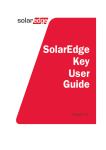
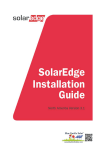
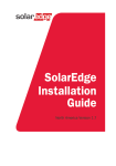
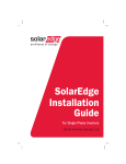
Disclaimers Disclaimers Important Notice Copyright © SolarEdge Inc. All rights reserved. No part of this document may be reproduced, stored in a retrieval system or transmitted, in any form or by any means, electronic, mechanical, photographic, magnetic or otherwise, without the prior written permission of SolarEdge Inc. The material furnished in this document is believed to be accurate and reliable. However, SolarEdge assumes no responsibility for the use of this material. SolarEdge reserves the right to make changes to the material at any time and without notice. You may refer to the SolarEdge web site (www.solaredge.com) for the most updated version. All company and brand products and service names are trademarks or registered trademarks of their respective holders. Patent marking notice: see http://www.solaredge.us/groups/patent Exclusion of Liability The general terms and conditions of delivery of SolarEdge shall apply. The content of these documents is continually reviewed and amended, where necessary. However, discrepancies cannot be excluded. No guarantee is made for the completeness of these documents. FCC Compliance This equipment has been tested and found to comply with the limits for a Class B digital device, pursuant to part 15 of the FCC Rules. These limits are designed to provide reasonable protection against harmful interference in a residential installation. This equipment generates, uses and can radiate radio frequency energy and, if not installed and used in accordance with the instructions, may cause harmful interference to radio communications. However, there is no guarantee that interference will not occur in a particular installation. If this equipment does cause harmful interference to radio or television reception, which can be determined by turning the equipment OFF and ON, you are encouraged to try to correct the interference by one or more of the following measures: Reorient or relocate the receiving antenna. Increase the separation between the equipment and the receiver. Connect the equipment into an outlet on a circuit different from that to which the receiver is connected. Consult the dealer or an experienced radio/TV technician for help. Changes or modifications not expressly approved by the party responsible for compliance may void the user’s authority to operate the equipment. SolarEdge Power Optimizers Installation Guide – MAN-01-00112-1.2 1 Support and Contact Information Support and Contact Information If you have technical queries concerning our products, please contact us: Australia 1800 465 567 APAC (Asia Pacific) [email protected] o:[email protected] [email protected] Belgium 080073041 [email protected] France 0800917410 [email protected] Germany +49 89-45459730 [email protected] Italy 800 784 824 [email protected] Japan +81.3.5530.9360 [email protected] United Kingdom 0800 028 1183 [email protected] US & Canada 1 877 360 5292 [email protected] Greece 00800125574 Israel +972 73 240-3118 Netherlands 08000221089 Worldwide +972 73 240-3118 Fax +972 73 240-3117 [email protected] Before contacting, make sure to have the following information at hand: Model and serial number of the product in question The error indicated on the inverter screen or on the SolarEdge monitoring portal, if there is such an indication. System configuration information, including the type and number of modules connected and the number and length of strings. The communication method to the SolarEdge monitoring portal, if the site is connected 2 SolarEdge Power Optimizers Installation Guide – MAN-01-00112-1.2 Table of Contents Table of Contents Disclaimers ......................................................................................................................... 1 Important Notice ...............................................................................................................1 Exclusion of Liability ...........................................................................................................1 FCC Compliance .................................................................................................................1 Support and Contact Information ....................................................................................... 2 Table of Contents ............................................................................................................... 3 Chapter 1: Safety ................................................................................................................ 4 SAFETY SYMBOLS ...............................................................................................................4 SAFETY INSTRUCTIONS ......................................................................................................4 Chapter 2: Introducing the SolarEdge Power Optimizers ..................................................... 7 Chapter 3: Power Optimizer Installation ............................................................................. 8 Site Installation General Workflow ....................................................................................8 Planning the Power Optimizers Installation.....................................................................10 Planning Connection to SolarEdge Inverters ........................................................................... 10 Planning Connection to non-SolarEdge inverters (with or without Safety & Monitoring Interface) ................................................................................................................................. 11 Installation Equipment List ..............................................................................................11 Package Contents ............................................................................................................12 Installing the Power Optimizer ........................................................................................12 Step 1, Mounting and Grounding the Power Optimizers......................................................... 12 Step 2, Connecting a Module to a Power Optimizer................................................................ 14 Step 3, Connecting Power Optimizers in Strings...................................................................... 14 Step 4, Providing Installation Information ............................................................................... 15 Step 5, Verifying Proper Power Optimizer Connection............................................................ 15 Step 6, Disabling SafeDC™ (Only when Connecting to Non-SolarEdge Inverters without SMI) 16 Step 7, Commissioning ............................................................................................................ 17 Appendix A: Troubleshooting ........................................................................................... 18 For Installations with SolarEdge Inverters .......................................................................18 For Installations with Non-SolarEdge Inverters ...............................................................19 SolarEdge Power Optimizers Installation Guide – MAN-01-00112-1.2 3 Chapter 1: Safety Chapter 1: Safety During installation, testing and inspection adherence to all the handling and safety instructions is mandatory. SAFETY SYMBOLS The following safety symbols are used in this document. Familiarize yourself with the symbols and their meaning before installing or operating the system. WARNING! Denotes a hazard. It calls attention to a procedure that, if not correctly performed or adhered to, could result in injury or loss of life. Do not proceed beyond a warning note until the indicated conditions are fully understood and met. Dénote un risque: il attire l'attention sur une opération qui, si elle n'est pas faite ou suivi correctement, pourrait causer des blessures ou un danger de mort. Ne pas dépasser une telle note avant que les conditions requises soient totallement comprises et accomplies. CAUTION: Denotes a hazard. It calls attention to a procedure that, if not correctly performed or adhered to, could result in damage or destruction of the product. Do not proceed beyond a caution sign until the indicated conditions are fully understood and met. Dénote un risque: il attire l'attention sur une opération qui, si elle n'est pas faite ou suivi correctement, pourrait causer un dommage ou destruction de l'équipement. Ne pas dépasser une telle note avant que les conditions requises soient totallement comprises et accomplies. NOTE: Denotes additional information about the current subject. IMPORTANT SAFETY FEATURE: Denotes information about safety issues. SAFETY INSTRUCTIONS The following notes and warnings apply when installing the power optimizers: WARNING: When modifying an existing installation, turn OFF the inverter ON/OFF switch, the AC/DC Safety Switch and the AC switch of the main circuit board. Avant de faire ces étapes, éteignez l'onduleur monophasé en mettant sur OFF l'interrupteur ON/OFF situé au bas de l'onduleur. WARNING Input and ouput connectors are not watertight until mated. Open connectors should be mated to each other or plugged with appopriate watertight caps. Les connecteurs d’entrée et sortie ne sont pas étanches jusqu'à ce qu’ils soient accouplés. Les connecteurs doivent être accouplés ou fermés avec des terminaux étanches. CAUTION: This unit must be operated according to the operating specifications in this document. Cette unité doit être opérée suivant les instructions trouvées dans ce document. CAUTION: Cutting the power optimizer input or output cable connector is prohibited and will void the warranty. Sectionner les cables d’entrées ou de sortie de l’optimiseur est interdit et annule sa garantie. 4 SolarEdge Power Optimizers Installation Guide – MAN-01-00112-1.2 Chapter 1: Safety CAUTION: Choose a mounting location where optimizers will not be submerged in water. Choisissez le lieu de montage tel que l’optimiseur ne puisse pas être submergé par l’eau. CAUTION: If you intend to mount the optimizers directly to the module or module frame, first consult the module manufacturer for guidance regarding the mounting location and the impact, if any, on module warranty. Drilling holes in the module frame should be done according to the module manufaturer instructions. Pour installation à même le module ou la monture du module, consultez d'abord le fabricant du module sur la position et son impact sur la garantie du module. Le perçage de trous dans le cadre du module devra se faire suivant les instructions du fabricant. CAUTION: Installing a SolarEdge system without ensuring compatibility of the module connectors with the optimizer connectors may be unsafe and could cause functionality problems such as ground faults, resulting in inverter shut down. In order to ensure mechanical compatibility of the SolarEdge optimizers and the modules to which they are connected: Use identical connectors from the same manufacturer and of the same type on both the power optimizers and on the modules; or Verify that the connectors are compatible in the following way: ▪ The connector manufacturer should explicitly verify compatibility with the SolarEdge optimizer connector; and ▪ A third-party test report by one of the listed external labs (TUV, VDE, Bureau Veritas UL, CSA, InterTek) should be obtained, verifying the compatibility of the connectors. Les connecteurs du module doivent être mécaniquement compatibles avec les optimiseurs de puissance. Sinon, le système SolarEdge installé peut être dangereux ou causer des problèmes fonctionnels, tels que les défauts de terre, qui peuvent provoquer un arrêt de l’onduleur. Afin d'assurer la compatibilité mécanique entre les optimiseurs de puissance SolarEdge et les modules auxquels ils sont connectés, il faut : Utiliser des connecteurs identiques du même fabricant et du même type aussi bien pour les optimiseurs de puissance que pour les modules. Vérifiez que les connecteurs sont compatibles de la manière suivante: ▪ Le fabricant du connecteur doit explicitement vérifier la compatibilité avec le connecteur SolarEdge. ▪ Un rapport de test de tierce partie doit être effectué par l’un des laboratoires externes indiqués ci-dessous:(TUV, VDE, Bureau Veritas UL, CSA,Intertek), qui vérifiera la compatibilité des connecteurs. NOTE: All modules in the same installation must be equipped with power optimizers. NOTE: The maximum installation altitude is 4000m / 13124 ft. NOTE: The symbol appears at grounding points on the SolarEdge equipment. This symbol is also used in this manual. SolarEdge Power Optimizers Installation Guide – MAN-01-00112-1.2 5 Chapter 1: Safety IMPORTANT SAFETY FEATURE: Each power optimizer is equiped with a SafeDC mechanism which ensures the optimizer outputs a safe 1V voltage until connected to the SolarEdge inverter or SMI, and the inverter/SMI are turned ON. When connecting the power optimizers to a non-SolarEdge inverter without a Safety and monitoring Interface, you must disable the SafeDC before connecting to the inverter. Refer to the SolarEdge Key manual for more information on how to disable the SafeDC After disabling the SafeDC, opatimizers will always output the module voltage regardless of inverter state. The following table summarizes the safety considerations when using the power optimizers: DC Mode With SolarEdge inverter With non-SolarEdge With noninverter, with SMI SolarEdge inverter, without SMI Safe DC - 1V PV Module Voltage 6 Optimizer is not connected, or AC is OFF, or The inverter ON/OFF switch is turned OFF. Inverter is ON Optimizer is not connected, or Never AC is OFF, or The inverter ON/OFF switch is turned OFF. SMI is ON Always SolarEdge Power Optimizers Installation Guide – MAN-01-00112-1.2 Chapter 2: Introducing the SolarEdge Power Optimizers Chapter 2: Introducing the SolarEdge Power Optimizers SolarEdge power optimizers are DC-DC converters connected to PV modules in order to maximize power harvesting by performing Maximum Power Point Tracking (MPPT) at the module level. Power optimizers with SolarEdge’s new IndOP™ (Independent Optimization) technology can operate without additional hardware interface and work directly with any non-SolarEdge inverter as well as with the broad range of SolarEdge inverters. Power optimizers with P/N starting with "OPI", “OPJ” or “PxxxI” have the IndOP™ feature. Each power optimizer transmits its module’s performance data over the DC power line. When using a SolarEdge inverter, these signals are received by the inverter and can be used for maintenance and remote monitoring. To monitor the modules when using a non-SolarEdge inverter, add a SolarEdge Safety and monitoring interface device (purchased separately). Monitoring the optimizers is not mandatory for generating power. SolarEdge Power Optimizers Installation Guide – MAN-01-00112-1.2 7 Chapter 3: Power Optimizer Installation Chapter 3: Power Optimizer Installation Site Installation General Workflow The following is the workflow for installing and setting up a new site, using a SolarEdge inverter or a nonSolarEdge one (with or without SMI). Most of these procedures can also be used for modifying an existing site. This manual describes only the power optimizer installation. Installing with Non-SolarEdge Inverter With SMI Installing with NonSolarEdge Inverter Without SMI Connecting power optimizers to modules and in a string Refer to page 14 Recording power optimizer serial numbers Refer to page 15 Installing the SMI Refer to the SolarEdge SMI Manual Connecting power optimizers to modules and in a string Refer to page 14 Recording power optimizer serial numbers Refer to page 15 Installing the non-SolarEdge inverter Refer to the specific inverter manual Disabling SafeDC™ Refer to page 16 Connecting the strings to the SMI Installing the non- SolarEdge inverter Commissioning and activating the installation Connecting the SMI to the SolarEdge monitoring server (optional) Refer to the specific inverter manual Refer to the inverter manual and SMI Manual Refer to the SolarEdge SMI Manual Connecting the strings to the inverter Refer to the specific inverter manual Commissioning and activating the installation Configuring the SMI (optional) 8 SolarEdge Power Optimizers Installation Guide – MAN-01-00112-1.2 Chapter 3: Power Optimizer Installation Installing with SolarEdge Inverter Connecting power optimizers to modules and in a string Refer to page 14 Recording power optimizer serial numbers Refer to page 15 Installing the SolarEdge inverter Connecting the strings to the inverter Refer to SolarEdge Inverter Installation Manual Commissioning and activating the installation Connecting the inverter to the SolarEdge monitoring server (optional) Configuring the inverter (optional) SolarEdge Power Optimizers Installation Guide – MAN-01-00112-1.2 9 Chapter 3: Power Optimizer Installation Planning the Power Optimizers Installation Plan the installation according to the inverters to be used. The following sections describe the planning considerations when using SolarEdge inverters, and when using non-SolarEdge inverters, with or without the Safety & Monitoring Interface. Planning Connection to SolarEdge Inverters You can create parallel strings of unequal length, that is, the number of power optimizers in each string does not have to be the same. Use the minimum and maximum string lengths, depending on the inverter type. The string lengths are specified in Power Optimizer Datasheets supplied with the power optimizers. Refer to the SolarEdge Site Designer for string length verification. Completely shaded modules cause their power optimizers to temporarily shut down. This will not affect the performance of the other power optimizers in the string as long as the minimum number of power optimizers connected to unshaded modules meet the minimum required string voltage. If under typical conditions fewer than the minimum number of optimizers is connected to unshaded modules, add more optimizers to the string. Refer to the SolarEdge Site Designer for verification. You can download the software from http://www.solaredge.com/groups/support/downloads Figure 1: Power Optimizers Connected in Series to SolarEdge Inverter 10 SolarEdge Power Optimizers Installation Guide – MAN-01-00112-1.2 Chapter 3: Power Optimizer Installation Planning Connection to non-SolarEdge inverters (with or without Safety & Monitoring Interface) Refer to the inverter manual and modules datasheets. Use the non-SolarEdge inverter design rules, referring to the PV modules as installed without optimization. WARNING! Designing strings that are not according to the inverter design rules may result in permanent damage to the inverter. Figure 2: Power optimizers connected in series to a non-SolarEdge inverter via Safety & Monitoring Interface Figure 3: Power optimizers connected in series directly to a non-SolarEdge inverter Installation Equipment List Standard tools can be used during the installation of the SolarEdge power optimizer. The following is a recommendation of the equipment to be used: Drilling machine and bits suitable for the surface on which the optimizer will be installed 1/4’’ or 5/16” screws, springs and washers for attaching the power optimizer to the racking Screwdriver Voltmeter When installing a non- SolarEdge inverter without SMI – SolarEdge Key SolarEdge Power Optimizers Installation Guide – MAN-01-00112-1.2 11 Chapter 3: Power Optimizer Installation Package Contents Power optimizers Datasheet This manual Grounding washers (North America only) Installing the Power Optimizer Step 1, Mounting and Grounding the Power Optimizers 1 Use the power optimizer mounting brackets to attach the power optimizer to the racking, as described below. 2 Determine the power optimizer mounting location. 3 If required, mark all mounting hole locations and drill the holes. CAUTION: Do not drill through the power optimizer or through the mounting holes. The drilling vibrations can damage the power optimizer and will void the warranty. Ne pas percer à travers la optimiseur de puissance ou ses trous de fixation. Les vibrations qui en résulteraient peuvent endommager la optimiseur de puissance. 4 Attach each power optimizer to the rack using the 5/16'' or 1/4'' screws and washers. 5 For North America only - use the following methods to ground the power optimizer: For mounting on a grounded metal rail: Use the provided 5/16'' stainless steel star washer between the railing and the flat side of the mounting bracket. The grounding washer should break through the anodize coating of the railing to ensure low-resistive connection. Apply torque of 9.5 N*m / 7 lb*ft. Star washer Mounting Bracket Figure 4: Power optimizer grounding using the star washer 12 SolarEdge Power Optimizers Installation Guide – MAN-01-00112-1.2 Chapter 3: Power Optimizer Installation For mounting on rails with sliding nut fasteners, or on an un-grounded structure (such as a wooden structure): Connect an equipment-grounding conductor to the grounding terminal according to the supplied instructions (the terminal should be purchased separately1*). The grounding terminal accepts a wire size of 6-14 AWG, and must be sized for equipment grounding per NEC 250.122 requirements. Tighten the screws connecting the power optimizer to the frame and the grounding terminal screw. Apply torque of 9.5 N*m / 7 lb*ft. WARNING: The metallic enclosure of the power optimizer must be grounded in accordance with the requirements of the Local and National Codes. L'enceinte métallique de l’optimiseur de puissance doit être mise à la terre en accord avec les régulations locales et nationales.. Optional grounding terminal Figure 5: Power optimizer grounding terminal For rest of the world – all power optimizers are double insulated and grounding is not required. NOTE: Record power optimizer serial numbers and locations, as described in Step 4, Providing Installation Information on page 15. 6 * Verify that each power optimizer is securely attached. For additional information, refer to http://www.solaredge.com/files/pdfs/se-product-update-dcd-c-grounding-lug.pdf. SolarEdge Power Optimizers Installation Guide – MAN-01-00112-1.2 13 Chapter 3: Power Optimizer Installation Step 2, Connecting a Module to a Power Optimizer Connect the Plus (+) output connector of the module to the Plus (+) input connector of the power optimizer. Connect the Minus (-) output connector of the module to the Minus (-) input connector of the power optimizer. WARNING! Verify that you have identified the inputs correctly. The power optimizer input cables are the short ones. Do not connect modules to power optimizer outputs. Output + - + - Input Connect to module Figure 6: Power optimizer connectors Step 3, Connecting Power Optimizers in Strings ► To connect a string of modules: 1 Connect the Minus (-) output connector of the string’s first power optimizer to the Plus (+) output connector of the string’s second power optimizer. 2 Connect the rest of the power optimizers in the string in the same way. 3 While the modules are exposed to sunlight, verify correct polarity by measuring the string polarity with a voltmeter. + - + - Figure 7: Power optimizers connected in series 14 SolarEdge Power Optimizers Installation Guide – MAN-01-00112-1.2 Chapter 3: Power Optimizer Installation 4 Connect to the inverter according to the installation plan (refer to Planning the Power Optimizers Installation on page 10). NOTE: When the installation is done with SMI, the cable length between power optimizers and the SMI should not exceed 150m Step 4, Providing Installation Information If you intend to monitor the installation using the SolarEdge monitoring portal, it is recommended to record the physical location of each power optimizer. Use the following methods to provide this information. Paper Template Fill out the Physical Layout Template using the detachable 2D barcode stickers on each power optimizer. Once the form is completed, scan it and upload the scanned file to the SolarEdge monitoring portal during site registration. For an example paper template, refer to http://www.solaredge.com/files/pdfs/physicallayout-template.pdf. For detailed information, refer to the SolarEdge Site Mapping Template Application Note, available on the SolarEdge website at http://www.solaredge.com/files/pdfs/application_note_using_site_mapping_template.pdf. iPhone Site Mapper Use the SolarEdge Site Mapper iPhone application to scan the power optimizers and inverter 2D barcodes. It then creates a file that can be uploaded to the SolarEdge monitoring portal during site registration. The SolarEdge Site Mapper can be downloaded from the Apple iTunes Store. For detailed information, refer to the SolarEdge Site Mapper Software Guide or to the Site Mapper demo movie, available on the SolarEdge website at http://www.solaredge.com/groups/installer-tools/sitemapper Step 5, Verifying Proper Power Optimizer Connection After a module is connected to a power optimizer, the power optimizer outputs a safe voltage of 1V. Therefore, the total string voltage should be equal to 1V times the number of power optimizers connected in series in the string. For example, if 10 power optimizers are connected in a string, then 10V should be produced. 1 Measure the voltage of each string individually before connecting it to the other strings or to the AC/DC Safety Switch. 2 Use a voltmeter with at least 0.1V measurement accuracy. 3 Make sure the modules are exposed to sunlight during this process; otherwise, the power optimizers may not be powered. If you use a tracker, the power optimizer will turn ON only if the tracker is tracking the sun and at least 2W are provided by the module. SolarEdge Power Optimizers Installation Guide – MAN-01-00112-1.2 15 Chapter 3: Power Optimizer Installation Step 6, Disabling SafeDC™ (Only when Connecting to Non-SolarEdge Inverters without SMI) WARNING! In installations with SolarEdge Inverters or with SMI, make sure that the SafeDC™ is enabled for all the power optimizers. NOTE: This section is relevant only when connecting power optimizers to a non-SolarEdge inverter and not using the SolarEdge Safety & Monitoring Interface. SolarEdge power optimizers are provided in a SafeDC mode: when connected to a PV module these power optimizers will output a safe voltage of 1VDC until they are paired either with a SolarEdge inverter or with the SolarEdge Safety & Monitoring Interface, and until power production has started. When connecting power optimizers directly to a non-SolarEdge inverter without a Safety and monitoring Interface, disabling the SafeDC mode is required using the SolarEdge Key product. For more information, refer to the SolarEdge Key User Manual available on the SolarEdge website at http://www.solaredge.com/groups/support/downloads. Display SafeDC Enable Button SafeDC Disable Button On/OFF Button Connection to String Figure 8: The SolarEdge Key ► 1 To disable the SafeDC mode: Press the ON/OFF button ( ) to turn the SolarEdge Key ON. The message Vo XXX appears on the SolarEdge Key LCD. XXX is the most recent string voltage measurement. NOTE: Only one string of power optimizers can be connected to a SolarEdge Key (4-30 power optimzers). 2 16 Connect the Plus (+) connector of the string of optimizers to the Plus (+) input connector of the SolarEdge Key. Connect the Minus (-) output connector of the string of optimizers to the Minus (-) input connector of the SolarEdge Key (see Figure 9). SolarEdge Power Optimizers Installation Guide – MAN-01-00112-1.2 Chapter 3: Power Optimizer Installation 3 Disable the SafeDC (refer to the SolarEdge Key User Manual (http://www.solaredge.com/groups/support/downloads) The SafeDC mode is now disabled and the voltage of each power optimizer equals the voltage of the module (Voc). WARNING: The DC cables carry a high voltage and the power optimizers no longer output a safe 1V output. PROCEED WITH CARE! 4 Disconnect the string cables and proceed with commissioning. Figure 9: SolarEdge Key connection Step 7, Commissioning Connect the strings to the inverter: When connecting to SolarEdge inverters, or to non-SolarEdge inverters with SMI, perform the Commissioning steps as described in the SolarEdge Inverter Installation Manual, or SolarEdge SMI Installation Manual, available on the SolarEdge website at http://www.solaredge.com/groups/support/downloads. All the power optimizers must be logically paired to the inverter/SMI. The power optimizers do not start producing power until they are paired with an inverter. When connecting to non-SolarEdge inverters without SMI, pairing is not required. Perform the Commissioning steps of the non-SolarEdge inverter as described in its manual. SolarEdge Power Optimizers Installation Guide – MAN-01-00112-1.2 17 Appendix A: Troubleshooting Appendix A: Troubleshooting For Installations with SolarEdge Inverters Problem Possible Cause Possible Solution String voltage is 0V Output of one or more power optimizers is disconnected Connect all power optimizer outputs String voltage not 0V but lower than no. of optimizers One or more of the power optimizers are not connected in the string Connect all power optimizers One or more of the modules are not connected properly to their power optimizer inputs Connect the modules to the optimizer inputs Wrong polarity connection on one of the strings Check polarity of the string output using a voltmeter and correct if needed. An extra power optimizer is connected in the string Check if an extra power optimizer is connected in the string. If not – proceed to next solution. A module is connected directly to the string, without a power optimizer. Verify that only power optimizers are connected in the string and that no module outputs are connected without a power optimizer. If the problem persists, proceed to the next step. A malfunction of one of the power optimizers Disconnect the wires that connect the power optimizers in the string. Measure the output voltage of each power optimizer in order to locate the power optimizer that does not output the 1V safety voltage. If a malfunctioning power optimizer is located, check its connections, polarity, module and voltage. If a malfunction cannot be bypassed or resolved, skip the malfunctioning power optimizer, thus connecting a shorter string. Do not continue before finding the problem and replacing the malfunctioning power optimizer. String voltage higher than the number of optimizers WARNING! If the measured voltage is too high, the installation may not have a safe low voltage. PROCEED WITH CARE! A deviation of ±1% per string is reasonable. Si la tension mesuree est trop haute, la tension basse de securite pourrait manquer dans l’installation. REDOUBLEZ DE PRECAUTION. Une deviation de ±1% par string est raisonnable. SafeDC mode was disabled using the SolarEdge Key 18 Enable the SafeDC. SolarEdge Power Optimizers Installation Guide – MAN-01-00112-1.2 Appendix A: Troubleshooting For Installations with Non-SolarEdge Inverters Problem String voltage is 0V Possible Cause Diagnostics/Possible Solution Output of one or more power optimizers is disconnected Check/connect all power optimizer outputs PV Modules are connected to power optimizers with reversed polarity Check the PV module polarity using a voltmeter, and correct if needed Fuse is blown / DC circuit breaker is disconnected Replace the fuse, or connect DC circuit breaker. The Fuse/Circuit breaker should support current of 15A or higher Insufficient number of modules in the string Verify that the number of modules connected in the string is according to the inverter's design rules. Refer to the Inverter Manual or PV module datasheets to determine minimum string length One or more of the power optimizers are not connected in the string For installation with safety & monitoring interface: 1. Turn OFF the SMI 2. Wait ~30sec until all optimizers are in SafeDC mode 3. Measure the string output using a voltmeter 4. If the string output is less than the number of optimizers, check and/or connect all power optimizers 5. Conduct pairing String voltage is lower than minimum input voltage of the inverter For installations without safety & monitoring interface - check / connect all power optimizers Wrong polarity connection on one of the strings Check polarity of the string output using a voltmeter and correct if needed. One or more of the modules are not connected properly to their power optimizer inputs For installation with safety & monitoring interface: 1. Turn OFF the SMI 2. Wait ~30sec until all optimizers are in SafeDC mode 3. Measure the string output using a voltmeter SolarEdge Power Optimizers Installation Guide – MAN-01-00112-1.2 19 Appendix A: Troubleshooting Problem String voltage is higher than the maximum range of the inverter. The inverter is not waking up 20 Possible Cause Diagnostics/Possible Solution 4. If the string output is less than the number of optimizers, check and/or connect all power optimizers One or more power optimizers have SafeDC enabled For installation with safety & monitoring interface - conduct pairing (refer to the SMI manual) For installations without safety & monitoring interface - use the SolarEdge Key to disable SafeDC The number of PV modules is above the maximum string size allowed by the inverter. Verify that the number of modules connected in the string is according to the inverter design rules. Refer to the inverter manual or module datasheet to determine the maximum string length The inverter voltage is below wakeup voltage Refer to inverter manual or module datasheet to determine the minimum string length SolarEdge Power Optimizers Installation Guide – MAN-01-00112-1.2